structure and release behavior in controlled drug delivery...
TRANSCRIPT

Structure and Release Behavior in
Controlled Drug Delivery Devices
David M. Saylor
U.S. Food and Drug Administration
Computational Homology Workshop
Georgia Tech, Atlanta, GA
February 4, 2006

Contributors
Theory and Computation:
Chang-Soo Kim (FDA)
Jim Warren (NIST)
Experimental:
Dinesh Patwardhan (FDA)
Benita Dair (FDA)
Ken McDermott (FDA)
Homology:
Tom Wanner (GMU)

Controlled Drug Delivery• Drug is incorporated into a matrix material (polymer)
– diffusion barrier = reduced release rate
Time
Fra
ction D
rug
Deliv
ere
d
0.0
0.2
0.4
0.6
0.8
1 .0
“pure”
“controlled”
Supply a sustained safe
and effective dose of drug
to target media
dru
g
fra
ctio
n
1.0
0.0
drug +
matrix
pure
drugtarget
media

Controlled Delivery Devices
transdermal
patches
extended release
tablets
targeted
chemotherapydrug eluting
stent

Drug Eluting Stent (DES)
Coronary disease:
Future: other devices coated with CDD systems
Problem:restenosis
Solution:DES
traditional treatment =bare metal stent

DES Manufacture
bare metal stent
(316 stainless steel)
drug + polymer
dissolved in solvent
Paralene C
drug + polymer
polymer (optional)
Structure will depend on materials
and manufacture conditions

drug-richphase
- drug molecule
- polymer molecule
polymer-richphase
Drug-Polymer Microstructures
drugfraction
1.00.0

Microstructure Impacts Kinetics
Time
Fra
ction
Dru
g D
eliv
ere
d
0.0
0.2
0.4
0.6
0.8
1.0
Microstructure: spatial variation in
chemical and physical composition
40% drug
drugfraction
1.00.0

Example: Microstructure v. Kinetics
Wormuth, DeWitt, and Haugstad,
Polymer Preprints 2005, 46(2), 1222
increased phaseseparation
Elution of dexamethasone from thin coatings ofpoly(alkylmethacrylates) on stents
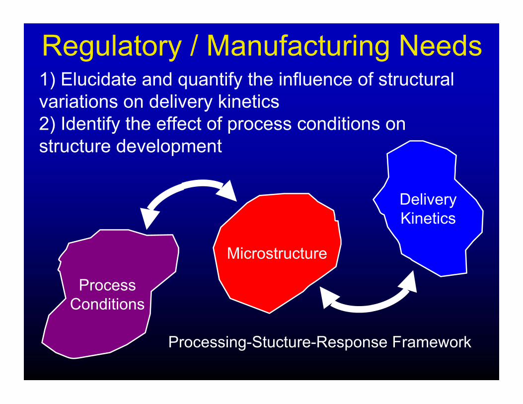
Regulatory / Manufacturing Needs1) Elucidate and quantify the influence of structural
variations on delivery kinetics
2) Identify the effect of process conditions on
structure development
Processing-Stucture-Response Framework
Delivery
Kinetics
Microstructure
Process
Conditions
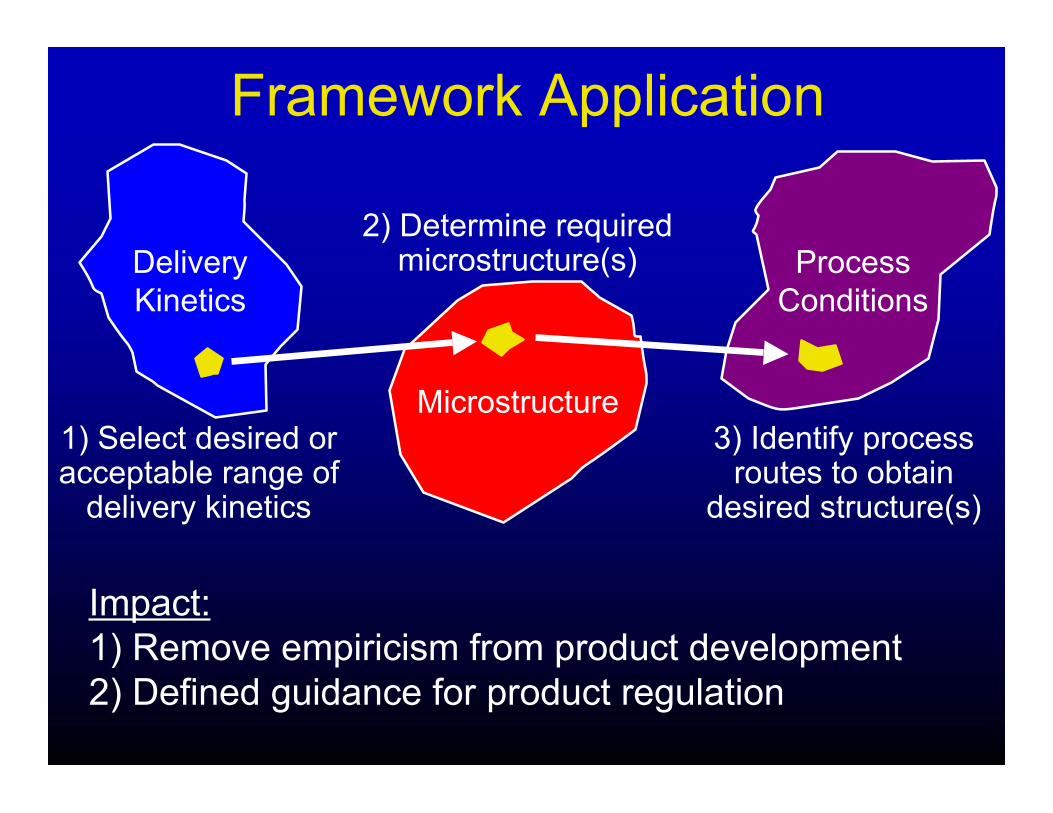
Framework Application
Impact:
1) Remove empiricism from product development
2) Defined guidance for product regulation
Delivery
Kinetics
Microstructure
Process
Conditions
1) Select desired oracceptable range of
delivery kinetics
2) Determine requiredmicrostructure(s)
3) Identify processroutes to obtain
desired structure(s)

Objective:
Approach:
To develop tools that will enable the inter-relationships
between processing, microstructure, and delivery
kinetics to be quantified.
1) Theory/Computation
- develop theoretical and numerical tools to predict structural
evolution in CDD systems
- computational experiments (manufacture and deliver)
2) Laboratory
- fabricate CDD systems under different process conditions
- dissolve systems to characterize delivery kinetics
3) Quantitative Description of Microstructure
- computational homology

Theory
Overview:
• Thermodynamics provides driving force for evolution
• Kinetics governs speed of evolution
• Three (3) components: drug, polymer, and solvent
• Order parameter: amorphous or crystalline
• Diffusive transport phenomena (mixing and separation)
• Phase transformations (e.g. crystallization)
• Heterogeneous and homogenous nucleation
A set of partial differential equations, based on fundamental
materials chemistry and physics, that govern the evolution of
a system of materials.

System Specific Parameters
crystalline
amorphous
• Variables in equations are material system specific
thermodynamic and kinetic parameters.
• Determined by: experiment, chemical group theory, molecular
dynamics, educated guess
Thermodynamics
Material system:
polymer = PLA (biodegradable)
drug = Sirolimus
solvent (processing) = THF
solvent (delivery) = isopropanol

Application of TheoryNumerical methods used to solve the equations in space and
time yielding structural evolution:
Processing
drugsolvent
polymer
amorphous crystalline
t =
0t =
t*
composition order

Evolution During Delivery
drugsolvent
polymer
amorphous
crystalline
t = 0 t = t*
co
mp
ositio
no
rde
r

Computational ExperimentsCharacterize microstructure evolution during manufacturing:
• Drug:Polymer = 0.50:0.50
• Dissolve in Solvent
• Evaporate off Solvent
drugsolvent
polymer
amorphous
crystalline
co
mp
ositio
no
rde
r

Evaporation RateAlthough evaporation is not in the theory explicitly,
time of evolution is a qualitative measure
drugsolvent
polymer
“fast”
“slow”
evapora
tion
rate

Evaporation is Coming!drug : polymer : solvent = 15 : 15 : 70
Psolvent = P Psolvent = 0.5 P
composition order composition order
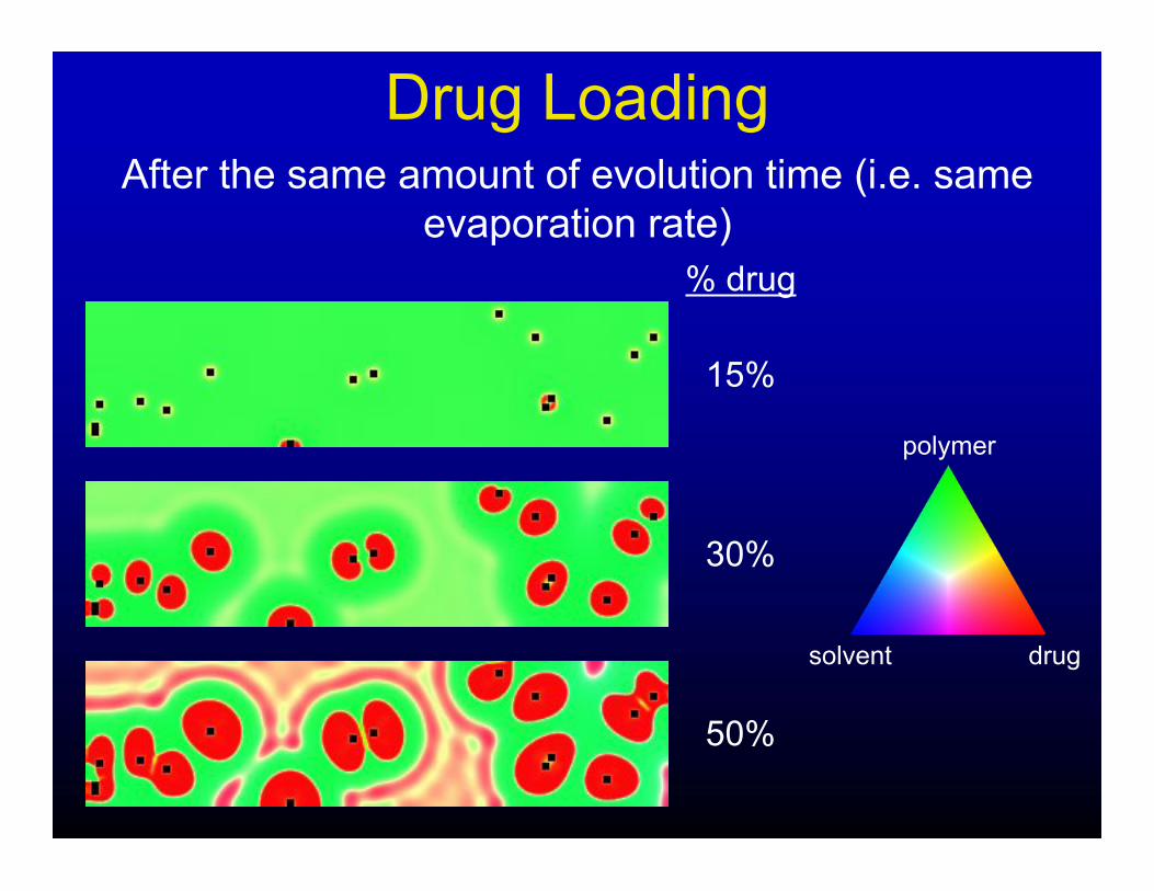
Drug LoadingAfter the same amount of evolution time (i.e. same
evaporation rate)
% drug
30%
50%
15%
drugsolvent
polymer

Process-Structure Relations
Extend over other variables (e.g. materials, temperature, etc.)
drug loading
15%
30%
50%
evapora
tion r
ate
“slo
w”
“fast”
drugsolvent
polymer

• 30% drug - “medium” evaporation rate
• dissolve composite in solvent (biodegradable polymer)
Evolution During Delivery
drugsolvent
polymer

Delivery Kinetics
drugsolvent
polymer

30% Drug Delivery KineticsMicrostructures formed with 30%
drug at varying evaporation rates:
drugsolvent
polymer
“medium”
“slow”
“fast”

Delivery Kinetics v. Composition
drugsolvent
polymer
Microstructures formed at “medium” evaporation
rate with varying compositions:
15%
30%
50%

Processing-Structure-Response
drug loading
15%
30%
50%
evapora
tion r
ate
“slo
w”
“fast”
delivery kinetics

1) Theory/Computation
- develop theoretical and numerical tools to predict structural
evolution in CDD systems
- computational experiments (manufacture and deliver)
2) Laboratory
- fabricate CDD systems under different process conditions
- dissolve systems to characterize delivery kinetics
3) Quantitative Description of Microstructure
- computational homology
Objective:
Approach:
To develop tools that will enable the inter-relationships
between processing, microstructure, and delivery
kinetics to be quantified.

Laboratory Experiments1) Sample fabrication
2) Microstructure characterization
3) Dissolution testing
polymerdrug
solvent

Sample Fabrication
Polymer = SIBS Drug = Tetracycline
Note: Material system is different from computational experiments
(e.g. polymer is non-biodegradable)
Process Variability Matrix:
Material System:Solvent = THF
dru
g:p
oly
mer
T(°C)40°C23°C
15:8
530:7
0
3 3
33

Microstructure v. Processing
100µm
30%
dru
g23°C
15%
dru
g40°C
drug particles

30% Drug Comparison
23°C (phase separated)
40°C (homogeneous)
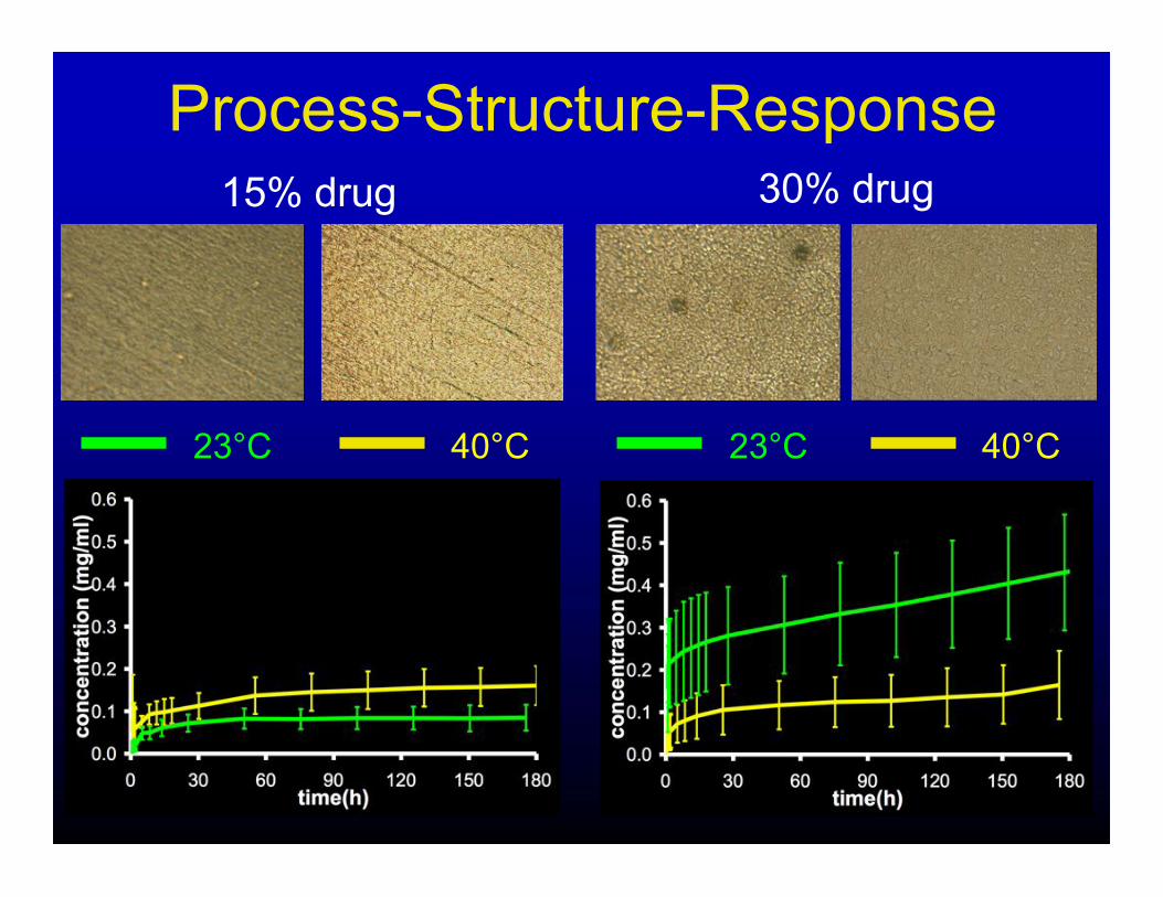
Process-Structure-Response
23°C 40°C
15% drug 30% drug
23°C 40°C

1) Theory/Computation
- develop theoretical and numerical tools to predict structural
evolution in CDD systems
- computational experiments (manufacture and deliver)
2) Laboratory
- fabricate CDD systems under different process conditions
- dissolve systems to characterize delivery kinetics
3) Quantitative Description of Microstructure
- computational homology
Objective:
Approach:
To develop tools that will enable the inter-relationships
between processing, microstructure, and delivery
kinetics to be quantified.

Microstructure QuantificationMapping requires a statistical representation of
microstructure, i.e. a metric.
Delivery
KineticsMicrostructure
Process
Conditions
Require a metric for microstructure that is:
1) robust enough to distinguish between structures that yield
significantly different responses
2) relatively simple

Processing-Structure-Response
drug loading
15%
30%
50%
evapora
tion r
ate
“slo
w”
“fast”
delivery kinetics
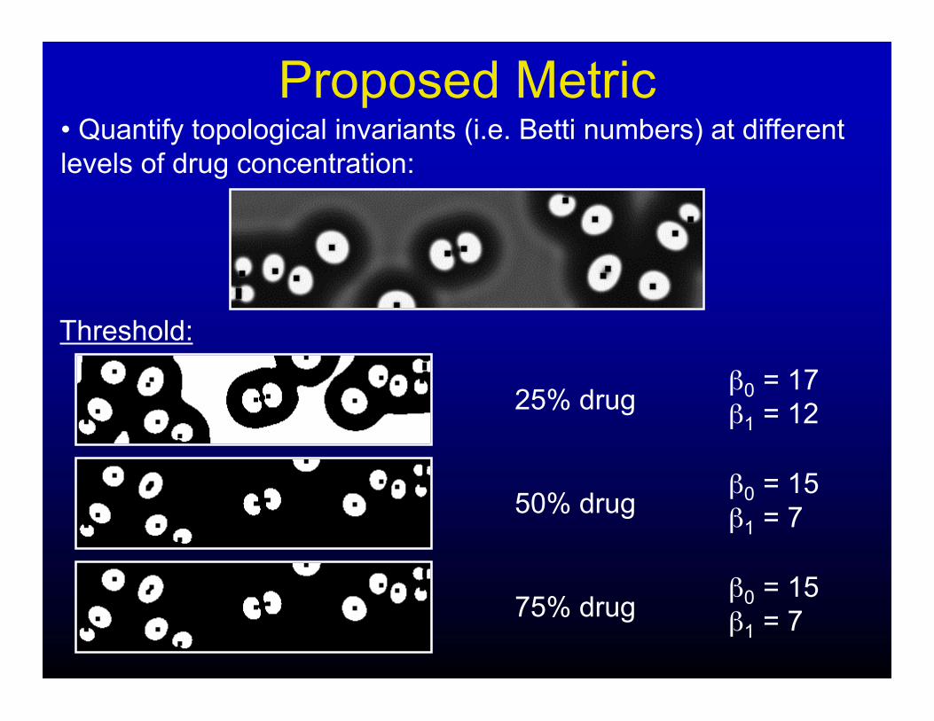
Proposed Metric• Quantify topological invariants (i.e. Betti numbers) at different
levels of drug concentration:
Threshold:
25% drug
50% drug
75% drug
!0 = 17
!1 = 12
!0 = 15
!1 = 7
!0 = 15
!1 = 7

Topology “Signal”
• Map of !i per unit volume as a function of
threshold level:
!0 = 17
!1 = 12
!0 = 15
!1 = 7
!0 = 15
!1 = 7

Microstructure Classification• Topology "signal" can be used to quantify and classify
variations in microstructure
• Structures with topologically similar distributions of drug will
yield quantitatively similar "signals”, i.e. considered statistically
identical
drugsolvent
polymer

Evaporation v. Homology30% drug, variable evaporation rate:
“slow”
“fast”
evapora
tion
rate

Drug Loading v. Homology“medium” evaporation rate, variabledrug content:
15% drug
30% drug
50% drug

Homology v. Delivery KineticsMicrostructures formed with 30%
drug at varying evaporation rates:“medium”
“slow”
“fast”

Processing-Homology-Response
drug loading
15%
30%
50%
evapora
tion r
ate
“slo
w”
“fast”
delivery kinetics

Objective:
Approach:
To develop tools that will enable the inter-relationships
between processing, microstructure, and delivery
kinetics to be quantified.
1) Theory/Computation
- develop theoretical and numerical tools to predict structural
evolution in CDD systems
- computational experiments (manufacture and deliver)
2) Laboratory
- fabricate CDD systems under different process conditions
- dissolve systems to characterize delivery kinetics
3) Quantitative Description of Microstructure
- computational homology

Clinically Desired KineticsGoal: tailor delivery kinetics to a particular application
Desired or acceptable delivery kinetics depends
on the application:
time
Dru
g R
ele
ased cytotoxic
cytostaticmetabolic
rate
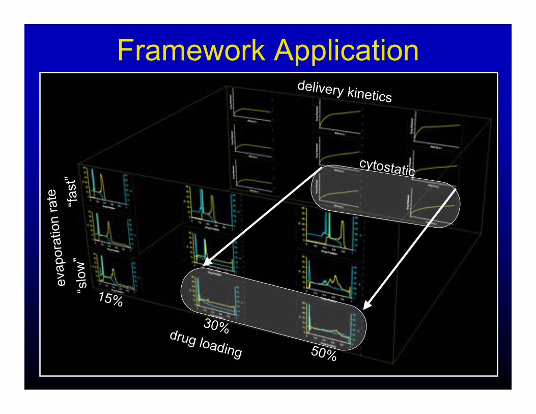
Framework Application
drug loading
15%
30%
50%
evapora
tion r
ate
“slo
w”
“fast”
delivery kinetics
cytostatic

Summary• Developed theoretical and computation tools to predict
microstructural evolution (processing & release conditions) in
controlled drug delivery systems.
• Complementary laboratory experiments are being conducted
to elucidate these same relationships and to provide validation
for the theory.
• A relatively simple microstructural metric based on
computational homology has been proposed to link
quantitatively the system microstructure with delivery kinetics
and processing routes.
• These tools can be used to build quantitative processing -
structure - response relations that can provide strict,
quantitative guidelines for device design and provide the basis
for product review decisions.

Appropriate Metric?Q. Is the proposed metric sufficient, i.e. does it provide
adequate resolution in microstructure space?
Q. Is there another relatively simple metric based on topological
measures that would be better?
Q. Is microstructure topology an appropriate measure for this
application?
vs.
e.g. !i(d) d