sts-134/ulf6 - nasa · 2011-05-22 · sts-134/ulf6 fd 09 execute package msg page(s) title 082a 1 -...
TRANSCRIPT
STS-134/ULF6 FD 09 Execute Package
MSG Page(s) Title
082A 1 - 16 FD09 Flight Plan Revision
083 17 FD09 Mission Summary
084 18 - 21 ULF6 EVA Grease Gun Cleanup
085 22 - 23 STS-134/ULF6 FD9 EVA DELTAS
086 24 - 47 STS-134/ULF6 EVA3 TIMELINE UPDATES
088A 48 - 49 FD09 ULF6 SODF Warning PCN Incorporation
089 50 - 54 BRT Ballstack Stiffness Adjustment
091 --- FD9 Event Summary Message (KPIX-TV, KGO-TV and KFBK-Radio) (Not Distributed)
092A --- FD9 Event Summary Message (The Daily, KDKA, Pittsburgh Tribune-Review and KTRK) (Not Distributed)
093 55 STORRM Cable Troubleshooting
094 56 EVA Camera Power Switch Mod
095 57 - 59 EVA 3 IR Camera For VADER Imagery
096 60 - 65 ULF6 FD9 Stowage Notes
097 66 - 68 Node 3 CDRA Bed 201 R&R Big Picture Words
098 69 FD9 Crew Choice Downlink Opportunities
099 70 - 71 Star Pairs Pad and Cue Card Update
079 72 ULF6 Stowage Overview for FD09
Approved by FAO: M. Scheib Approved by OpsPlan: J. Kitchen
Last Updated: May 22 2011 12:23 AM GMT JEDI (Joint Execute package Development and Integration), v3.0

MSG 082A (28-0015) - FD09 FLIGHT PLAN REVISION Page 1 of 16
Page 1 of 16, MSG 082A (28-0015)
MSG INDEX 1 MSG NO. TITLE 2 082 FD09 Flight Plan Revision 3 083 FD09 Mission Summary 4 084 ULF6 EVA Grease Gun Cleanup 5 085 STS-134/ULF6 FD9 EVA Deltas 6 086 STS-134/ULF6 EVA3 Timeline Updates 7 088 FD09 ULF6 SODF Warning PCN Incorporation 8 089 BRT Ballstack Stiffness Adjustment Procedure 9 091 FD9 Event Summary Message (KPIX-TV, KGO-TV and KFBK-Radio) 10 092 FD9 Event Summary Message (The Daily, KDKA, Pittsburgh Tribune-Review 11 and KTRK) 12 093 STORRM Cable Troubleshooting 13 094 EVA Camera Power Switch Mod 14 095 EVA 3 IR Camera For VADER Imagery 15 096 ULF6 FD9 Stowage Notes 16 097 Node 3 CDRA Bed 201 R&R Big Picture Words 17 098 FD9 Crew Choice Downlink Opportunities 18 099 Star Pairs Pad and Cue Card Update 19 079 ULF6 Stowage Overview for FD09 20 21 22
1. Post-Sleep Cryo Config 23 For today's post-sleep cryo config, O2 tanks 1 & 2, and H2 tanks 1 & 5 will be active. 24 25
R1 O2,H2 MANF VLV TK1 (two) - OP (tb-OP) 26 O2 TK2 HTRS A,B (two) - AUTO 27 28
A15 CRYO TK5 HTR O2 A - OFF 29 30
2. Pre-Sleep Cryo Config 31 √MCC for deltas prior to configuring for pre-sleep. 32
33 For tonight's pre-sleep cryo config, manifold 1 will be closed with O2 and 34 H2 tanks 1 & 5 active. 35
36 A15 CRYO TK5 HTR O2 A - AUTO 37
38 R1 O2 TK2 HTRS A,B (two) - OFF 39
O2,H2 MANF VLV TK1 (two) - CL (tb-CL) 40 41
3. EVA Camera 42 Today Ron will be performing an EVA Camera Turnaround task for the two cameras 43 you will take outside on EVAs 3 and 4. To prevent another camera from turning off 44 unintentionally, he'll be taping the power switch in the ON position. Reference MSG 45 094 for details. 46 47 48 49 50 51 52
1

MSG 082A (28-0015) - FD09 FLIGHT PLAN REVISION Page 2 of 16
Page 2 of 16, MSG 082A (28-0015)
1 4. STORRM Cable Troubleshooting 2
Mark/Drew, On FD7 during the VNS data retrieval from DRU1, the data transmission 3 halted several times with a duration of half an hour to an hour each. As a result, 4 we've added a STORRM CABLE TROUBLESHOOTING procedure (reference 5 Message 093)prior to the FD9 STORRM DAILY ACT. We still have about another 6 hour of data to retrieve from DRU1 before we start retrieving the rest of the data from 7 DRU3. Therefore, you'll run the STORRM DAILY ACT as written (vs. powering down 8 either DRU immediately after activation as has been done on previous days). We've 9 then added a callout in the afternoon to powerdown DRU1 after we complete the 10 data retrieval to prevent it from potentially overheating. Then, at the end of the 11 day, you'll perform STORRM DAILY DEACT. 12
13 5. IENOS 14
Roberto, Since the IENOS LEDs are no longer blinking, you can remove them from 15 the LAB and stow them for return. We have added IENOS deactivation and stow to 16 your timeline today. 17
18 6. EVA Mark, Drew, Taz, and Spanky - we have several messages for you today. Let 19
us know if you have any questions reviewing the new EVA3 Procedures. Good luck 20 on EVA3!!! 21
o MSG 28-005 (134-085) STS134-ULF6 FD9 EVA DELTAS contains words on 22 your Glove Photos, Suit Cleaning, and Water Mitigation for EMU 3005. The 23 MSG also contains updates to EVA 3 Tool Config., items for EVA 3 24 procedure review, and A/L Prep. 25
o MSG 28-006 (134-086) STS-134/ULF6 EVA3 TIMELINE UPDATES has 26 EVA3 Procedure Updates. Your new EVA3 Tool Config is included in this 27 message. Also, reference this message for the EVA IR Camera Setup/Task 28 Review and Procedure Review activities today. 29
o MSG 27-0604 (134-084) STS-134/ULF6 EVA GREASE GUN CLEANUP has 30 the procedure for the Grease Gun Cleanup task today. 31
o During EVA 1 and 2 it was reported that BRT Ballstacks felt ‘loose’. MSG 32
28-0012 (134-089) BRT Ballstack Stiffness Adjustment Procedure contains 33 the procedure steps to adjust the stiffness of the BRT Ballstack. If you desire 34 to adjust your BRT and time permits during EVA Tool Config or EVA 35 Procedure Review, it is okay to perform this procedure on one BRT at at time. 36 Please perform a verification test before starting the procedure on another 37 BRT. If more time is required, Grease Gun Clean up can be deferred to a 38 later date. Please let MCC-H know if this adjustment is performed. 39
40 7. STAR PAIRS PAD 41
MSG 099 has the Updated Star Pairs Pad and Cue Card. These go into effect at 42 MET 8/00:00. This replaces MSG 002. 43 44
8. STOWAGE OPS 45 For Box and Roberto: We have uplink message 134-79: ULF6 Stowage Overview for 46 FD9. This contains the current stowage plan for your Stowage Ops Activities on 47 todays timeline. 48 49 50 51
2

MSG 082A (28-0015) - FD09 FLIGHT PLAN REVISION Page 3 of 16
Page 3 of 16, MSG 082A (28-0015)
1 9. STS-134/ULF6 FD08 - MMT Summary 2 The MMT met briefly today to review the orbiter systems and mission progress. 3 Endeavour and her crew continue to perform in an outstanding fashion. The team is 4 Looking forward to the upcoming undocking of the 25S Soyuz and the imagery 5 capture that is planned for that event. 6 7
10. CDRA R&R 8 Mark - For an overview of the CDRA Bed R&R, please reference MSG 097 (28- 9 0013) Node 3 CDRA Bed 201 R&R Big Picture Words. 10 11
11. MERLIN 12 Taz - Today you will be moving the contents of MERLIN (LAB1O4_B1) into 13 MERLIN2 (LAB1O4_D1), removing the desiccants from MERLIN, and propping the 14 door open so the unit can dry out prior to return on ULF-7. Any questions on this 15 activity should be directed to Huntsville. 16
17 12. REPLACE PAGES 2-28, 2-30 AND 2-32, AND 3-90 THROUGH 3-99. 18
19 20 21 22 23 24 25 26 27 28 29 30 31 32 33 34 35 36 37 38 39 40 41 42 43 44 45 46 47 48 49 50
3

FLT PLN/134/FLIGHT
FD08 FD09
NO
MARK
BOX
SPANKY
ROBERTO
DREW
TAZ
%MNVR SENSOR PROTECT
^25S UNDOCK
REPLANNED
[A] NO EXERCISE [ISS MNVR]
2-28
STS 134
ISS
13 14 15 16 17 18 19 20 21 22 23 05/24GMT 05/23/11 (143) 007/00 01 02 03 04 05 06 07 08 09 10 11 12
MET Day 007
CDR POSTSLEEP
PRE SLEEPPMCA/G
PRE SLEEP SLEEPOFFDUTY
PLTLOG
POSTSLEEP
IMU
EXERCISE
PRE SLEEP SLEEP
STR TRK*
OMS^
MS1 POSTSLEEP
PRE SLEEP
MDDK#
SLEEPOFFDUTY
MS2LOG
POSTSLEEP
PAO
EVENT
PRE SLEEP SLEEPOFFDUTY
PRE SLP
MS3 POSTSLEEP
PRE SLEEP SLEEPOFFDUTY
OBSS%
MS4LOG
POSTSLEEP
PRE SLEEP SLEEPOFFDUTY
OBSS%
EXERCISE NO EXERCISE [A]
DAY/NIGHTORBIT 111 112 113 114 115 116 117 118 119
TDRSWEZ
TDRS AVAILBIAS -XLV -ZVV 25S RM BIAS -XLV -ZVVORB ATT
*CLOSE DOORS^ACCUM REPRESS
#STATUS CHECKNOTES
2-28
FD08 FD09
NO
MARK
BOX
SPANKY
ROBERTO
DREW
TAZ
%MNVR SENSOR PROTECT
^25S UNDOCK
REPLANNED
[A] NO EXERCISE [ISS MNVR]
STS 134
ISS
13 14 15 16 17 18 19 20 21 22 23 05/24GMT 05/23/11 (143) 007/00 01 02 03 04 05 06 07 08 09 10 11 12
MET Day 007
CDR POSTSLEEP
PRE SLEEPPMCA/G
PRE SLEEP SLEEPOFFDUTY
PLTLOG
POSTSLEEP
IMU
EXERCISE
PRE SLEEP SLEEP
STR TRK*
OMS^
MS1 POSTSLEEP
PRE SLEEP
MDDK#
SLEEPOFFDUTY
MS2LOG
POSTSLEEP
PAO
EVENT
PRE SLEEP SLEEPOFFDUTY
PRE SLP
MS3 POSTSLEEP
PRE SLEEP SLEEPOFFDUTY
OBSS%
MS4LOG
POSTSLEEP
PRE SLEEP SLEEPOFFDUTY
OBSS%
EXERCISE NO EXERCISE [A]
DAY/NIGHTORBIT 111 112 113 114 115 116 117 118 119
TDRSWEZ
TDRS AVAILORB ATT BIAS -XLV -ZVV 25S RM BIAS -XLV -ZVV
NOTES*CLOSE DOORS^ACCUM REPRESS
#STATUS CHECK
4

FLT PLN/134/FLIGHT
FD09
NO
MARK
BOX
ROBERTO
DREW
TAZ
SPANKY
REPLANNED
2-30
STS 134
ISS
01 02 03 04 05 06 07 08 09 10 11 12GMT 05/24/11 (144) 12 13 14 15 16 17 18 19 20 21 22 23 008/00
MET Day 007
CDR POST SLEEPIMU
MEAL OFF DUTY
EVA PROC
EXERCISE
CWC#6
INIT
CWC#6
TERM
CWC XFER
STR TRK&
OFFDUTY
PFCISSOCA
STRMACT
STRM T/S
STORRM*
PAO
EVENT
CDRA-REAR-UTILITIES
PLT POST SLEEP
EVA PROC
MEAL EXERCISE OFF DUTYFILTERINSPECT
STOWAGE OPS
BRIEF
OBSS
UNDOCK
WCS
PAOEVENT
POSTSLEEP
PFCOCA
MS1 POST SLEEP EVA TOOL CONFIG MEAL
EVA PROC
EXERCISE OFF DUTYOGS INSTLQDMATE
PAO
EVENT
RPCM R&RE_LKPREP
MS2
IENOS
STOW
POST SLEEP EXERCISE
EVA PROC
MEAL OFF DUTY
MDDK#
STOWAGE OPS PCN INCORP
OBSS
UNDOCK
PAO S/U
PAO S/U
MS3 POST SLEEP EXERCISEMEAL
EVA PROC
EVA TOOL CONFIGE_LK PREP OFF DUTY
BATT
INSTL
GREASE
GUN
CLEANUP
EVA IR CAMERA SETUP
REBA*
MS4D2XS
D2XS
POST SLEEP EXERCISEEVA TOOLCONFIG
EVA PROC
MEAL OFF DUTYOGS INSTLACCESS
PAO
EVENT
PAOEVENT
POST SLEEP
MERLIN
EXERCISEDAY/NIGHTORBIT 119 120 121 122 123 124 125 126 127
TDRSWEZ
TDRS AVAILBIAS -XLV -ZVVORB ATT
&OPEN DOORS *DRU 1 PWRDN#STATUS CHECKNOTES
2-30
FD09
NO
MARK
BOX
ROBERTO
DREW
TAZ
SPANKY
REPLANNED
STS 134
ISS
01 02 03 04 05 06 07 08 09 10 11 12GMT 05/24/11 (144) 12 13 14 15 16 17 18 19 20 21 22 23 008/00
MET Day 007
CDR POST SLEEPIMU
MEAL OFF DUTY
EVA PROC
EXERCISE
CWC#6
INIT
CWC#6
TERM
CWC XFER
STR TRK&
OFFDUTY
PFCISSOCA
STRMACT
STRM T/S
STORRM*
PAO
EVENT
CDRA-REAR-UTILITIES
PLT POST SLEEP
EVA PROC
MEAL EXERCISE OFF DUTYFILTERINSPECT
STOWAGE OPS
BRIEF
OBSS
UNDOCK
WCS
PAOEVENT
POSTSLEEP
PFCOCA
MS1 POST SLEEP EVA TOOL CONFIG MEAL
EVA PROC
EXERCISE OFF DUTYOGS INSTLQDMATE
PAO
EVENT
RPCM R&RE_LKPREP
MS2
IENOS
STOW
POST SLEEP EXERCISE
EVA PROC
MEAL OFF DUTY
MDDK#
STOWAGE OPS PCN INCORP
OBSS
UNDOCK
PAO S/U
PAO S/U
MS3 POST SLEEP EXERCISEMEAL
EVA PROC
EVA TOOL CONFIGE_LK PREP OFF DUTY
BATT
INSTL
GREASE
GUN
CLEANUP
EVA IR CAMERA SETUP
REBA*
MS4D2XS
D2XS
POST SLEEP EXERCISEEVA TOOLCONFIG
EVA PROC
MEAL OFF DUTYOGS INSTLACCESS
PAO
EVENT
PAOEVENT
POST SLEEP
MERLIN
EXERCISEDAY/NIGHT
ORBIT 119 120 121 122 123 124 125 126 127
TDRSWEZ
TDRS AVAILORB ATT BIAS -XLV -ZVV
NOTES&OPEN DOORS *DRU 1 PWRDN#STATUS CHECK
5

FLT PLN/134/FLIGHT
FD09 FD10
NO
MARK
BOX
SPANKY
ROBERTO
DREW
TAZ
REPLANNED
2-32
STS 134
ISS
13 14 15 16 17 18 19 20 21 22 23 05/25GMT 05/24/11 (144) 008/00 01 02 03 04 05 06 07 08 09 10 11 12
MET Day 008
CDR POST SLEEPSLEEPEVA PROC
PRE
SLEEP
PMCA/G
PRE SLEEP
OMS^
STRMD/A
PLTLOGPOST SLEEPSLEEPPRE SLEEPEVA PROC
IL ON
MS1 POST SLEEPSLEEPEVA PROC PRE SLEEP
MS2LOGPOST SLEEPSLEEPPRE SLEEPEVA PROC
MDDK#
MS3 POST SLEEPSLEEPEVA PROC PRE SLEEP
MS4 POST SLEEPSLEEPPRE SLEEPEVA PROC
EXERCISEDAY/NIGHTORBIT 127 128 129 130 131 132 133 134 135
TDRSWEZ
TDRS AVAILBIAS -XLV -ZVVORB ATT
^ACCUM REPRESS#STATUS CHECKNOTES
2-32
FD09 FD10
NO
MARK
BOX
SPANKY
ROBERTO
DREW
TAZ
REPLANNED
STS 134
ISS
13 14 15 16 17 18 19 20 21 22 23 05/25GMT 05/24/11 (144) 008/00 01 02 03 04 05 06 07 08 09 10 11 12
MET Day 008
CDR POST SLEEPSLEEPEVA PROC
PRE
SLEEP
PMCA/G
PRE SLEEP
OMS^
STRMD/A
PLTLOGPOST SLEEPSLEEPPRE SLEEPEVA PROC
IL ON
MS1 POST SLEEPSLEEPEVA PROC PRE SLEEP
MS2LOGPOST SLEEPSLEEPPRE SLEEPEVA PROC
MDDK#
MS3 POST SLEEPSLEEPEVA PROC PRE SLEEP
MS4 POST SLEEPSLEEPPRE SLEEPEVA PROC
EXERCISEDAY/NIGHT
ORBIT 127 128 129 130 131 132 133 134 135
TDRSWEZ
TDRS AVAILORB ATT BIAS -XLV -ZVV
NOTES^ACCUM REPRESS
#STATUS CHECK
6

FLT PLN/134/FLIGHT
09
MARK BOX SPANKY
UPLINKKU STBY
UPLINKβ21+MaskBox 40,41
25S UNDOCK >
REPLANNED
RENAUDMNVR
FD09 EZ ACTIVITIES:
√MDDK Duct Screen TEPC Status Check: Verify display is backlit Hard reboot: STS-2(WINDECOM), STS-3(KFX) & STS-4(RPOP)
3-90
STS-134/ULF6 FD
21:00
22:00
23:00
00:00
GMT
Date05/23(143)
08:00
09:00
10:00
11:00
12:00
MET
Day 007W E Z
TDRS
~
~ ~
D/N
ORB
116
117
118
119
~
25S
RM
~
BIAS -XLV -ZVV
ATT
CDR
POST-SLEEP ACTIVITY (ORB OPS, CREW SYS)
~
SLEEP
~
PLT
SLEEP LOGBOOK (SDBI 1634)POST-SLEEP ACTIVITY (ORB OPS, CREW SYS)
~
SLEEP
~
MS1
POST-SLEEP ACTIVITY (ORB OPS, CREW SYS)
~
SLEEP
~
NOEXERCISE[ISS MNVR]
~
NOTES
3-90
09
MARK BOX SPANKY
UPLINKKU STBY
UPLINKβ21+MaskBox 40,41
25S UNDOCK >
REPLANNED
RENAUDMNVR
FD09 EZ ACTIVITIES:
√MDDK Duct Screen TEPC Status Check: Verify display is backlit Hard reboot: STS-2(WINDECOM), STS-3(KFX) & STS-4(RPOP)
STS-134/ULF6 FD
21:00
22:00
23:00
00:00
GMT
Date05/23(143)
08:00
09:00
10:00
11:00
12:00
MET
Day 007W E Z
TDRS
D/N
ORB
116
117
118
119
ATT
~
25S
RM
~
BIAS -XLV -ZVV
CDR
~
POST-SLEEP ACTIVITY (ORB OPS, CREW SYS)
~
SLEEP
PLT
SLEEP LOGBOOK (SDBI 1634)
~
POST-SLEEP ACTIVITY (ORB OPS, CREW SYS)
~
SLEEP
MS1
~
POST-SLEEP ACTIVITY (ORB OPS, CREW SYS)
~
SLEEP
~
NOEXERCISE[ISS MNVR]
NOTES
7

FLT PLN/134/FLIGHT
09
ROBERTO DREW TAZ
25S UNDOCK >
REPLANNED
RENAUDMNVR
3-91
STS-134/ULF6 FD
21:00
22:00
23:00
00:00
GMT
Date05/23(143)
08:00
09:00
10:00
11:00
12:00
MET
Day 007W E Z
TDRS
~
~
~
D/N
ORB
116
117
118
119
~
25S
RM
~
BIAS -XLV -ZVV
ATT
MS2
SLEEP LOGBOOK (SDBI 1634)POST-SLEEP ACTIVITY (ORB OPS, CREW SYS)
~
SLEEP
~
MS3
POST-SLEEP ACTIVITY (ORB OPS, CREW SYS)
~
SLEEP
~
MS4
SLEEP LOGBOOK (SDBI 1634)POST-SLEEP ACTIVITY (ORB OPS, CREW SYS)
~
SLEEP
~
NOEXERCISE[ISS MNVR]
~
NOTES
3-91
09
ROBERTO DREW TAZ
25S UNDOCK >
REPLANNED
RENAUDMNVR
STS-134/ULF6 FD
21:00
22:00
23:00
00:00
GMT
Date05/23(143)
08:00
09:00
10:00
11:00
12:00
MET
Day 007W E Z
TDRS
D/N
ORB
116
117
118
119
ATT
~
25S
RM
~
BIAS -XLV -ZVV
MS2
SLEEP LOGBOOK (SDBI 1634)
~
POST-SLEEP ACTIVITY (ORB OPS, CREW SYS)
~
SLEEP
MS3
~
POST-SLEEP ACTIVITY (ORB OPS, CREW SYS)
~
SLEEP
MS4
SLEEP LOGBOOK (SDBI 1634)
~
POST-SLEEP ACTIVITY (ORB OPS, CREW SYS)
~
SLEEP
~
NOEXERCISE[ISS MNVR]
NOTES
8

FLT PLN/134/FLIGHT
09
MARK BOX SPANKY
REPLANNED
A L9 PAYLOAD STATION A/G (two) - OFF NETMEETING VIDEO CONFERENCING (ORB OPS, PGSC) Use A/G2 for audio Inform MCC which PGSC will be used
3-92
STS-134/ULF6 FD
01:00
02:00
03:00
04:00
GMT
Date05/24(144)
12:00
13:00
14:00
15:00
16:00
MET
Day 007W E Z
TDRS
~
~
D/N
ORB
119
120
121
~
~
BIAS -XLV -ZVV
ATT
CDR
POST-SLEEP ACTIVITY (ORB OPS, CREW SYS)
~
OPEN STAR TRACKER DOORS Ref. MSG 074
STORRM DAILY ACT (CC)STORRM CABLE TROUBLESHOOTING Ref. MSG 093
27-0387 CDRA DESSICANT/SORBENT BED 201(NOD3A4 ARS RACK) (In CDRA Book) Steps 2-6, 10.4, 10.5 Ref. MSG 097 for big picture words
~
PLT
POST-SLEEP ACTIVITY (ORB OPS, CREW SYS)
~
OBSS MNVR SENSOR PROTECT TO UNDOCK Ref. MSG 075, pg. 7-10
PUBLIC AFFAIRS EVENTSTS KU AVAIL: 15:41-16:12 Shuttle FD: Box/Taz Ref. MSG 091
~
POST-SLEEP ACTIVITY (ORB OPS, CREW SYS)
Private Family Conference KU TDRW (13:27-14:00) A
MS1
POST-SLEEP ACTIVITY (ORB OPS, CREW SYS)
~
EVA 3 TOOL CONFIGURATION (EVA, TIMELINES) Ref. STS-134 CONSUMABLES TRACKING CC Ref. MSG 085 and MSG 086
~
On MCC GO:IFM: 3.2.405 RPCM R&R LAB1D2 MCC-H will perform steps 1.4 and 5.2
ISS EVA SYSTEMS: 1.305 EQUIPMENT LOCK PREP
NOTES
3-92
09
MARK BOX SPANKY
REPLANNED
A L9 PAYLOAD STATION A/G (two) - OFF NETMEETING VIDEO CONFERENCING (ORB OPS, PGSC) Use A/G2 for audio Inform MCC which PGSC will be used
STS-134/ULF6 FD
01:00
02:00
03:00
04:00
GMT
Date05/24(144)
12:00
13:00
14:00
15:00
16:00
MET
Day 007W E Z
TDRS
D/N
ORB
119
120
121
ATT
~
~
BIAS -XLV -ZVV
CDR
~POST-SLEEP ACTIVITY (ORB OPS, CREW SYS)
OPEN STAR TRACKER DOORS Ref. MSG 074
STORRM DAILY ACT (CC)STORRM CABLE TROUBLESHOOTING Ref. MSG 093
~
27-0387 CDRA DESSICANT/SORBENT BED 201(NOD3A4 ARS RACK) (In CDRA Book) Steps 2-6, 10.4, 10.5 Ref. MSG 097 for big picture words
PLT
~POST-SLEEP ACTIVITY (ORB OPS, CREW SYS)
OBSS MNVR SENSOR PROTECT TO UNDOCK Ref. MSG 075, pg. 7-10
~
PUBLIC AFFAIRS EVENTSTS KU AVAIL: 15:41-16:12 Shuttle FD: Box/Taz Ref. MSG 091
POST-SLEEP ACTIVITY (ORB OPS, CREW SYS)
Private Family Conference KU TDRW (13:27-14:00) A
MS1
~POST-SLEEP ACTIVITY (ORB OPS, CREW SYS)
~
EVA 3 TOOL CONFIGURATION (EVA, TIMELINES) Ref. STS-134 CONSUMABLES TRACKING CC Ref. MSG 085 and MSG 086
On MCC GO:IFM: 3.2.405 RPCM R&R LAB1D2 MCC-H will perform steps 1.4 and 5.2
ISS EVA SYSTEMS: 1.305 EQUIPMENT LOCK PREP
NOTES
9

FLT PLN/134/FLIGHT
09
ROBERTO DREW TAZ
B Ref. STS-134 CONSUMABLES TRACKING CC
POST-SLEEP ACTIVITY (ORB OPS, CREW SYS)
REPLANNED
3-93
STS-134/ULF6 FD
01:00
02:00
03:00
04:00
GMT
Date05/24(144)
12:00
13:00
14:00
15:00
16:00
MET
Day 007W E Z
TDRS
~
~
D/N
ORB
119
120
121
~
~
BIAS -XLV -ZVV
ATT
MS2
IENOS OPERATIONS (ASSY OPS, PAYLOADS) Step 2
POST-SLEEP ACTIVITY (ORB OPS, CREW SYS)
~
EXERCISE
~
CGBA STATUS CHK; GLACIER STATUS CHK (CC)OBSS MNVR SENSOR PROTECT TO UNDOCK Ref. MSG 075, pg. 7-10
HD DIGITAL CC DLNLK (PHOTO/TV, CANON G1)
MS3
POST-SLEEP ACTIVITY (ORB OPS, CREW SYS)
~
EVA 3 TOOL CONFIGURATION (EVA, TIMELINES) Ref. STS-134 CONSUMABLES TRACKING CC Ref. MSG 085 and MSG 086
~
ISS EVA SYSTEMS: 1.305 EQUIPMENT LOCK PREP
ISS EVA SYSTEMS: 1.515 EMUMETOX/LIOH/BATTERY REPLACEMENT Ref: STS-134 CONSUMABLES TRACKING CC
ISS EVA SYS:1.307 REBA INSTALLATION/REMOVAL INSTALLATION B
MS4
Charge D2Xs battery for the D2Xs EVA Camera Configurations
POST-SLEEP ACTIVITY (ORB OPS, CREW SYS)
~
EXERCISE
PUBLIC AFFAIRS EVENTSTS KU AVAIL: 15:41-16:12 Shuttle FD: Box/Taz Ref. MSG 091
~
NOTES
3-93
09
ROBERTO DREW TAZ
B Ref. STS-134 CONSUMABLES TRACKING CC
POST-SLEEP ACTIVITY (ORB OPS, CREW SYS)
REPLANNED
STS-134/ULF6 FD
01:00
02:00
03:00
04:00
GMT
Date05/24(144)
12:00
13:00
14:00
15:00
16:00
MET
Day 007W E Z
TDRS
D/N
ORB
119
120
121
ATT
~
~
BIAS -XLV -ZVV
MS2
IENOS OPERATIONS (ASSY OPS, PAYLOADS) Step 2
~POST-SLEEP ACTIVITY (ORB OPS, CREW SYS)
~
EXERCISE
CGBA STATUS CHK; GLACIER STATUS CHK (CC)OBSS MNVR SENSOR PROTECT TO UNDOCK Ref. MSG 075, pg. 7-10
HD DIGITAL CC DLNLK (PHOTO/TV, CANON G1)
MS3
~POST-SLEEP ACTIVITY (ORB OPS, CREW SYS)
~
EVA 3 TOOL CONFIGURATION (EVA, TIMELINES) Ref. STS-134 CONSUMABLES TRACKING CC Ref. MSG 085 and MSG 086
ISS EVA SYSTEMS: 1.305 EQUIPMENT LOCK PREP
ISS EVA SYSTEMS: 1.515 EMUMETOX/LIOH/BATTERY REPLACEMENT Ref: STS-134 CONSUMABLES TRACKING CC
ISS EVA SYS:1.307 REBA INSTALLATION/REMOVAL INSTALLATION B
MS4
Charge D2Xs battery for the D2Xs EVA Camera Configurations
~POST-SLEEP ACTIVITY (ORB OPS, CREW SYS)
EXERCISE
~
PUBLIC AFFAIRS EVENTSTS KU AVAIL: 15:41-16:12 Shuttle FD: Box/Taz Ref. MSG 091
NOTES
10

FLT PLN/134/FLIGHT
09
MARK BOX SPANKY
PUBLIC AFFAIRS EVENT See pg. 3-92
D WCS Filter Check WCS CRADLE - AUTO INIBIT Inspect hose block filter, change if req'd WCS CRADLE - AUTO
C Ref. MSG 049, Step 8 Power Down DRU1
REPLANNED
3-94
STS-134/ULF6 FD
05:00
06:00
07:00
08:00
GMT
Date05/24(144)
16:00
17:00
18:00
19:00
20:00
MET
Day 007W E Z
TDRS
~
~
~
D/N
ORB
122
123
124
~
~
BIAS -XLV -ZVV
ATT
CDR
IMU STAR OF OPPORTUNITY ALIGN (ORB OPS,GNC)
MEAL
EXERCISE~
SHUTTLE/ISS H2O CONTAINER FILL (HC) (ORB OPS, ECLS) Perform CWC FILL #6 Ref. MSG 030
STORRM ACT WITH DRU POWERDOWN C
27-0387 CDRA DESSICANT/SORBENT BED 201(NOD3A4 ARS RACK) (In CDRA Book) Steps 2-6, 10.4, 10.5 Ref. MSG 097 for big picture words
~
PLT
MEAL
FILTER CLEANING (IFM, SCHEDULED MAINTENANCE) Inspect filters and clean as necessary
STOWAGE OPS Ref. MSG 079
STOWAGE BRIEF Call down status to MCC via A/G 2
WCS FILTER CHECK D
~
MS1
EVA 3 TOOL CONFIGURATION (EVA, TIMELINES) Ref. STS-134 CONSUMABLES TRACKING CC Ref. MSG 085 and MSG 086
~
MEAL
EXERCISE
OGS RECIRC LOOP CONTINUOUSREMEDIATION INSTALLATION Steps 5-6 Ref. MSG 052 ~
ECLSS: 1.912 OGS ACTIVATION - NODE 3 Steps 11 and 12
NOTES
3-94
09
MARK BOX SPANKY
PUBLIC AFFAIRS EVENT See pg. 3-92
D WCS Filter Check WCS CRADLE - AUTO INIBIT Inspect hose block filter, change if req'd WCS CRADLE - AUTO
C Ref. MSG 049, Step 8 Power Down DRU1
REPLANNED
STS-134/ULF6 FD
05:00
06:00
07:00
08:00
GMT
Date05/24(144)
16:00
17:00
18:00
19:00
20:00
MET
Day 007W E Z
TDRS
D/N
ORB
122
123
124
ATT
~
~
BIAS -XLV -ZVV
CDR
IMU STAR OF OPPORTUNITY ALIGN (ORB OPS,GNC)
MEAL
~EXERCISE
SHUTTLE/ISS H2O CONTAINER FILL (HC) (ORB OPS, ECLS) Perform CWC FILL #6 Ref. MSG 030
STORRM ACT WITH DRU POWERDOWN C
~27-0387 CDRA DESSICANT/SORBENT BED 201(NOD3A4 ARS RACK) (In CDRA Book) Steps 2-6, 10.4, 10.5 Ref. MSG 097 for big picture words
PLT
MEAL
FILTER CLEANING (IFM, SCHEDULED MAINTENANCE) Inspect filters and clean as necessary
STOWAGE OPS Ref. MSG 079
STOWAGE BRIEF Call down status to MCC via A/G 2
WCS FILTER CHECK D
~
MS1
~EVA 3 TOOL CONFIGURATION (EVA, TIMELINES) Ref. STS-134 CONSUMABLES TRACKING CC Ref. MSG 085 and MSG 086
MEAL
EXERCISE
~
OGS RECIRC LOOP CONTINUOUSREMEDIATION INSTALLATION Steps 5-6 Ref. MSG 052
ECLSS: 1.912 OGS ACTIVATION - NODE 3 Steps 11 and 12
NOTES
11

FLT PLN/134/FLIGHT
09
ROBERTO DREW TAZ
PUBLIC AFFAIRS EVENT See pg. 3-93
Charge D2Xs battery for the D2Xs EVA Camera Configurations
REPLANNED
E Remove dessicant packs from MERLIN in Locker-1 position. In step 7 relocate all internal items in MERLIN to MERLIN2. Stow the tray removed in step 2 per stowage note (MSG 096).
3-95
STS-134/ULF6 FD
05:00
06:00
07:00
08:00
GMT
Date05/24(144)
16:00
17:00
18:00
19:00
20:00
MET
Day 007W E Z
TDRS
~
~ ~
D/N
ORB
122
123
124
~
~
BIAS -XLV -ZVV
ATT
MS2
EXERCISE
~
MEAL
STOWAGE OPS Ref. MSG 079
FD09 ULF6 SODF WARNING PCN INCORP Ref. MSG 088
~
MS3
MEAL
EVA 3 TOOL CONFIGURATION (EVA, TIMELINES) Ref. STS-134 CONSUMABLES TRACKING CC Ref. MSG 085 and MSG 086
~
ULF6 EVA GREASE GUN CLEANUP Ref. MSG 084
ULF6 EVA IR CAMERA FOR VADER IMAGERY Ref. MSG 086 Ref. MSG 095 Steps 1-2
~
MS4
EVA 3 TOOL CONFIGURATION (EVA, TIMELINES) Ref. STS-134 CONSUMABLES TRACKING CC Ref. MSG 085 and MSG 086
MEAL
OGS RECIRC LOOP CONTINUOUSREMEDIATION INSTALLATION Steps 5-6 Ref. MSG 052 ~
OGS RECIRC LOOP CONTINUOUSREMEDIATION INSTALLATION Steps 2-4 Ref. MSG 052
~
US PODF: MERLIN: 6.012 MERLINDESICCANT REMOVAL E
NOTES
3-95
09
ROBERTO DREW TAZ
PUBLIC AFFAIRS EVENT See pg. 3-93
Charge D2Xs battery for the D2Xs EVA Camera Configurations
REPLANNED
E Remove dessicant packs from MERLIN in Locker-1 position. In step 7 relocate all internal items in MERLIN to MERLIN2. Stow the tray removed in step 2 per stowage note (MSG 096).
STS-134/ULF6 FD
05:00
06:00
07:00
08:00
GMT
Date05/24(144)
16:00
17:00
18:00
19:00
20:00
MET
Day 007W E Z
TDRS
D/N
ORB
122
123
124
ATT
~
~
BIAS -XLV -ZVV
MS2
~
EXERCISE
MEAL
STOWAGE OPS Ref. MSG 079
~
FD09 ULF6 SODF WARNING PCN INCORP Ref. MSG 088
MS3
MEAL
~EVA 3 TOOL CONFIGURATION (EVA, TIMELINES) Ref. STS-134 CONSUMABLES TRACKING CC Ref. MSG 085 and MSG 086
ULF6 EVA GREASE GUN CLEANUP Ref. MSG 084
~
ULF6 EVA IR CAMERA FOR VADER IMAGERY Ref. MSG 086 Ref. MSG 095 Steps 1-2
MS4
EVA 3 TOOL CONFIGURATION (EVA, TIMELINES) Ref. STS-134 CONSUMABLES TRACKING CC Ref. MSG 085 and MSG 086
MEAL
~
OGS RECIRC LOOP CONTINUOUSREMEDIATION INSTALLATION Steps 5-6 Ref. MSG 052
OGS RECIRC LOOP CONTINUOUSREMEDIATION INSTALLATION Steps 2-4 Ref. MSG 052
~
US PODF: MERLIN: 6.012 MERLINDESICCANT REMOVAL E
NOTES
12

FLT PLN/134/FLIGHT
09
MARK BOX SPANKY
EVA 3 PROCEDURE REVIEW See pg. 3-98
EVA 3 PROCEDURE REVIEW See pg. 3-98
EVA 3 PROCEDURE REVIEW See pg. 3-98
F PFC to be performed using S-Band via Public Call 4 for audio and Ku-Band for video. Please call down SSC preference before the conference and make sure that all applications expcept Netmeeting have been closed.
REPLANNED
3-96
STS-134/ULF6 FD
09:00
10:00
11:00
12:00
GMT
Date05/24(144)
20:00
21:00
22:00
23:00
00:00
MET
Day 007W E Z
TDRS
~
~
~
D/N
ORB
124
125
126
127
~
~
BIAS -XLV -ZVV
ATT
CDR
OFF DUTY
~
EXERCISE
~
SHUTTLE/ISS H2O CONTAINER FILL (HC) (ORB OPS, ECLS) Perform FILL TERMINATION
Transfer CWC to ISS
OFF DUTY
Private Family Conference FISS KU AVAIL (23:05-23:29)
PUBLIC AFFAIRS EVENT STS KU AVAIL: 21:46-22:14Shuttle FD: Mark/Spanky/Taz Ref. MSG 092
PLT
~
EXERCISE
OFF DUTY
MS1
~
OFF DUTY
OGS RECIRC LOOP CONTINUOUSREMEDIATION INSTALLATION Steps 5-6 Ref. MSG 052
~
PUBLIC AFFAIRS EVENT STS KU AVAIL: 21:46-22:14Shuttle FD: Mark/Spanky/Taz Ref. MSG 092
NOTES
3-96
09
MARK BOX SPANKY
EVA 3 PROCEDURE REVIEW See pg. 3-98
EVA 3 PROCEDURE REVIEW See pg. 3-98
EVA 3 PROCEDURE REVIEW See pg. 3-98
F PFC to be performed using S-Band via Public Call 4 for audio and Ku-Band for video. Please call down SSC preference before the conference and make sure that all applications expcept Netmeeting have been closed.
REPLANNED
STS-134/ULF6 FD
09:00
10:00
11:00
12:00
GMT
Date05/24(144)
20:00
21:00
22:00
23:00
00:00
MET
Day 007W E Z
TDRS
D/N
ORB
124
125
126
127
ATT
~
~
BIAS -XLV -ZVV
CDR
OFF DUTY
~
~
EXERCISE
SHUTTLE/ISS H2O CONTAINER FILL (HC) (ORB OPS, ECLS) Perform FILL TERMINATION
Transfer CWC to ISS
OFF DUTY
Private Family Conference FISS KU AVAIL (23:05-23:29)
PUBLIC AFFAIRS EVENT STS KU AVAIL: 21:46-22:14Shuttle FD: Mark/Spanky/Taz Ref. MSG 092
PLT
~
EXERCISE
OFF DUTY
MS1
~
OFF DUTY
~OGS RECIRC LOOP CONTINUOUSREMEDIATION INSTALLATION Steps 5-6 Ref. MSG 052
PUBLIC AFFAIRS EVENT STS KU AVAIL: 21:46-22:14Shuttle FD: Mark/Spanky/Taz Ref. MSG 092
NOTES
13

FLT PLN/134/FLIGHT
09
ROBERTO DREW TAZ
EVA 3 PROCEDURE REVIEW See pg. 3-99
EVA 3 PROCEDURE REVIEW See pg. 3-99
EVA 3 PROCEDURE REVIEW See pg. 3-99
REPLANNED
3-97
STS-134/ULF6 FD
09:00
10:00
11:00
12:00
GMT
Date05/24(144)
20:00
21:00
22:00
23:00
00:00
MET
Day 007W E Z
TDRS
~
~ ~
D/N
ORB
124
125
126
127
~
~
BIAS -XLV -ZVV
ATT
MS2
~
OFF DUTY
FD09 ULF6 SODF WARNING PCN INCORP Ref. MSG 088
~
HD DIGITAL CC DLNLK (PHOTO/TV, CANON G1)
MS3
EXERCISE
~
OFF DUTY
ULF6 EVA IR CAMERA FOR VADER IMAGERY Ref. MSG 086 Ref. MSG 095 Steps 1-2
~
MS4
~
OFF DUTY
OGS RECIRC LOOP CONTINUOUSREMEDIATION INSTALLATION Steps 5-6 Ref. MSG 052
~
PUBLIC AFFAIRS EVENT STS KU AVAIL: 21:46-22:14Shuttle FD: Mark/Spanky/Taz Ref. MSG 092
NOTES
3-97
09
ROBERTO DREW TAZ
EVA 3 PROCEDURE REVIEW See pg. 3-99
EVA 3 PROCEDURE REVIEW See pg. 3-99
EVA 3 PROCEDURE REVIEW See pg. 3-99
REPLANNED
STS-134/ULF6 FD
09:00
10:00
11:00
12:00
GMT
Date05/24(144)
20:00
21:00
22:00
23:00
00:00
MET
Day 007W E Z
TDRS
D/N
ORB
124
125
126
127
ATT
~
~
BIAS -XLV -ZVV
MS2
~
OFF DUTY
~FD09 ULF6 SODF WARNING PCN INCORP Ref. MSG 088
HD DIGITAL CC DLNLK (PHOTO/TV, CANON G1)
MS3
EXERCISE
~
OFF DUTY
~ULF6 EVA IR CAMERA FOR VADER IMAGERY Ref. MSG 086 Ref. MSG 095 Steps 1-2
MS4
~
OFF DUTY
~OGS RECIRC LOOP CONTINUOUSREMEDIATION INSTALLATION Steps 5-6 Ref. MSG 052
PUBLIC AFFAIRS EVENT STS KU AVAIL: 21:46-22:14Shuttle FD: Mark/Spanky/Taz Ref. MSG 092
NOTES
14

FLT PLN/134/FLIGHT
09
CREW WAKE AT 08/11:00
MARK BOX SPANKY
G C3 OMS ENG LEFT - ARM/PRESS (Wait 5 Seconds) - OFF
REPLANNED
3-98
STS-134/ULF6 FD
13:00
14:00
15:00
16:00
GMT
Date05/24(144)
00:00
01:00
02:00
03:00
04:00
MET
Day 008W E Z
TDRS
~
~
~
D/N
ORB
127
128
129
~
~
BIAS -XLV -ZVV
ATT
CDR
SLEEP
~
EVA 3 PROCEDURE REVIEW Ref. EVA 3 BRIEFING CARD (EVA, TIMELINES) Ref. MSG 085 and MSG 086
~
PRE-SLEEP ACTIVITY (ORB OPS, CREW SYS)
L9 PS AUD A/G 1,2 (two) - OFF PRIVATE MEDICAL CONFERENCEPrivate Conference via A/G 2
PRE-SLEEP ACTIVITY (ORB OPS, CREW SYS)
L OMS ACCUMULATOR REPRESS GSTORRM DAILY DEACT (CUE CARD)
PLT
SLEEP
~
PRE-SLEEP ACTIVITY (ORB OPS, CREW SYS)
EVA 3 PROCEDURE REVIEW Ref. EVA 3 BRIEFING CARD (EVA, TIMELINES) Ref. MSG 085 and MSG 086
~
ILLUMINATOR OPS (CC,TV) ILLUMINATORS ON-A,D
MS1
SLEEP
~
EVA 3 PROCEDURE REVIEW Ref. EVA 3 BRIEFING CARD (EVA, TIMELINES) Ref. MSG 085 and MSG 086
~
PRE-SLEEP ACTIVITY (ORB OPS, CREW SYS)
NOTES
3-98
09
CREW WAKE AT 08/11:00
MARK BOX SPANKY
G C3 OMS ENG LEFT - ARM/PRESS (Wait 5 Seconds) - OFF
REPLANNED
STS-134/ULF6 FD
13:00
14:00
15:00
16:00
GMT
Date05/24(144)
00:00
01:00
02:00
03:00
04:00
MET
Day 008W E Z
TDRS
D/N
ORB
127
128
129
ATT
~
~
BIAS -XLV -ZVV
CDR
~
SLEEP
~
EVA 3 PROCEDURE REVIEW Ref. EVA 3 BRIEFING CARD (EVA, TIMELINES) Ref. MSG 085 and MSG 086
PRE-SLEEP ACTIVITY (ORB OPS, CREW SYS)
L9 PS AUD A/G 1,2 (two) - OFF PRIVATE MEDICAL CONFERENCEPrivate Conference via A/G 2
PRE-SLEEP ACTIVITY (ORB OPS, CREW SYS)
L OMS ACCUMULATOR REPRESS GSTORRM DAILY DEACT (CUE CARD)
PLT
~
SLEEP
PRE-SLEEP ACTIVITY (ORB OPS, CREW SYS)
~
EVA 3 PROCEDURE REVIEW Ref. EVA 3 BRIEFING CARD (EVA, TIMELINES) Ref. MSG 085 and MSG 086
ILLUMINATOR OPS (CC,TV) ILLUMINATORS ON-A,D
MS1
~
SLEEP
~
EVA 3 PROCEDURE REVIEW Ref. EVA 3 BRIEFING CARD (EVA, TIMELINES) Ref. MSG 085 and MSG 086
PRE-SLEEP ACTIVITY (ORB OPS, CREW SYS)
NOTES
15

FLT PLN/134/FLIGHT
09
ROBERTO DREW TAZ
CREW WAKE AT 08/11:00
REPLANNED
3-99
STS-134/ULF6 FD
13:00
14:00
15:00
16:00
GMT
Date05/24(144)
00:00
01:00
02:00
03:00
04:00
MET
Day 008W E Z
TDRS
~
~ ~
D/N
ORB
127
128
129
~
~
BIAS -XLV -ZVV
ATT
MS2
SLEEP
~
PRE-SLEEP ACTIVITY (ORB OPS, CREW SYS)
EVA 3 PROCEDURE REVIEW Ref. EVA 3 BRIEFING CARD (EVA, TIMELINES) Ref. MSG 085 and MSG 086
~
CGBA STATUS CHK; GLACIER STATUS CHK (CC)
MS3
SLEEP
~
EVA 3 PROCEDURE REVIEW Ref. EVA 3 BRIEFING CARD (EVA, TIMELINES) Ref. MSG 085 and MSG 086
~
PRE-SLEEP ACTIVITY (ORB OPS, CREW SYS)
MS4
SLEEP
~
PRE-SLEEP ACTIVITY (ORB OPS, CREW SYS)
EVA 3 PROCEDURE REVIEW Ref. EVA 3 BRIEFING CARD (EVA, TIMELINES) Ref. MSG 085 and MSG 086
~
NOTES
3-99
09
ROBERTO DREW TAZ
CREW WAKE AT 08/11:00
REPLANNED
STS-134/ULF6 FD
13:00
14:00
15:00
16:00
GMT
Date05/24(144)
00:00
01:00
02:00
03:00
04:00
MET
Day 008W E Z
TDRS
D/N
ORB
127
128
129
ATT
~
~
BIAS -XLV -ZVV
MS2
~
SLEEP
PRE-SLEEP ACTIVITY (ORB OPS, CREW SYS)
~
EVA 3 PROCEDURE REVIEW Ref. EVA 3 BRIEFING CARD (EVA, TIMELINES) Ref. MSG 085 and MSG 086
CGBA STATUS CHK; GLACIER STATUS CHK (CC)
MS3
~
SLEEP
~
EVA 3 PROCEDURE REVIEW Ref. EVA 3 BRIEFING CARD (EVA, TIMELINES) Ref. MSG 085 and MSG 086
PRE-SLEEP ACTIVITY (ORB OPS, CREW SYS)
MS4
~
SLEEP
PRE-SLEEP ACTIVITY (ORB OPS, CREW SYS)
~
EVA 3 PROCEDURE REVIEW Ref. EVA 3 BRIEFING CARD (EVA, TIMELINES) Ref. MSG 085 and MSG 086
NOTES
16

MSG 083 - FD05 MISSION SUMMARY
END OF PAGE 1 OF 1, MSG 083
You are guys are doing a great job and having a good time doing it, keep it up! 1 2 YOUR CURRENT ORBIT IS: 187 X 183 NM 3 4 NOTAMS - 5 6
EDW - EDW 22L/04R IN USE. EDT 22R/04L EMERGENCY DAY USE ONLY. 7 EDW - LAKEBED RWYS RED. 8 NOR - LAKEBED RWYS GREEN. 9 HNL - RWY 08R/26L CLSD 10 NTU - RWY 05R/23L CLSD. 11 FFA - NOT USABLE. IN CARETAKER STATUS. 12 LAJ - RWY WIDTH REDUCED TO 154' - EAST SIDE OF RWY CLSD. 13 BEN - NOT USABLE. NOT SUPPORTED. 14 IKF - NOT USABLE. NO AGREEMENT 15
16 NEXT 2 PLS OPPORTUNITIES: 17 18 EDW22 ORB 126 – 7/22:57 SKC 7 240/12P19 19 EDW22 ORB 141 – 8/21:45 SKC 7 240/4P7 20 21 OMS TANK FAIL CAPABILITY: 22 23 NO 24 25 LEAKING OMS PRPLT BURN: 26 27 L or R OMS LEAK: ALWAYS BURN RETROGRADE 28 29 OMS QUANTITIES(%) 30 31 L OMS OX = 33.23 R OMS OX = 34.28 32 FU = 33.24 FU = 33.95 33 34 FOR CURRENT QTYS, SUBTRACT INCN’T COUNTER 35 36 DELTA V AVAILABLE: 37 38 OMS 346 FPS 39 ARCS (TOTAL ABOVE QTY1) 46 FPS 40 41 TOTAL IN THE AFT 392 FPS 42 43 ARCS (TOTAL ABOVE QTY2) 79 FPS 44 FRCS (ABOVE QTY 1) 32 FPS 45 46 AFT QTY 1 82 % 47 AFT QTY 2 44 % 48 49 50
17
27-0604 (MSG 084) ULF6 EVA GREASE GUN CLEANUP Page 1 of 4 pages
23 MAY 11
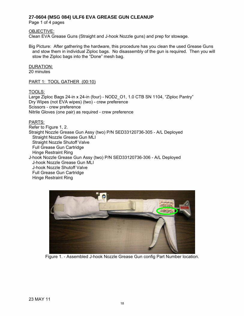
OBJECTIVE: Clean EVA Grease Guns (Straight and J-hook Nozzle guns) and prep for stowage. Big Picture: After gathering the hardware, this procedure has you clean the used Grease Guns
and stow them in individual Ziploc bags. No disassembly of the gun is required. Then you will stow the Ziploc bags into the “Done” mesh bag.
DURATION: 20 minutes PART 1: TOOL GATHER (00:10) TOOLS: Large Ziploc Bags 24-in x 24-in (four) - NOD2_O1, 1.0 CTB SN 1104, “Ziploc Pantry” Dry Wipes (not EVA wipes) (two) - crew preference Scissors - crew preference Nitrile Gloves (one pair) as required - crew preference PARTS: Refer to Figure 1, 2. Straight Nozzle Grease Gun Assy (two) P/N SED33120736-305 - A/L Deployed
Straight Nozzle Grease Gun MLI Straight Nozzle Shutoff Valve Full Grease Gun Cartridge Hinge Restraint Ring
J-hook Nozzle Grease Gun Assy (two) P/N SED33120736-306 - A/L Deployed J-hook Nozzle Grease Gun MLI J-hook Nozzle Shutoff Valve Full Grease Gun Cartridge Hinge Restraint Ring
Figure 1. - Assembled J-hook Nozzle Grease Gun config Part Number location.
18

27-0604 (MSG 084) ULF6 EVA GREASE GUN CLEANUP Page 2 of 4 pages
23 MAY 11
Figure 2. - Assembled Straight Nozzle Grease Gun Nomenclature.
PART 2: Grease Gun Cleanup and Stowage (00:10)
NOTE
The grease guns will be stowed assembled, therefore disassembly is not required. Removal of the grease gun MLI is not expected during the cleanup
1. Using Dry Wipes (not EVA wipes) with best effort, clean excess grease on Straight Nozzle Grease Gun with:
Nozzle, Refer to Figure 3 Inside and outside Tip MLI, Refer to Figure 4 Housing and Handle MLI, Refer to Figure 2
2. Using Dry Wipes (not EVA wipes) with best effort, clean excess grease on J-hook
Nozzle Grease Gun: Nozzle, Refer to Figure 3 Inside and outside Tip MLI, Refer to Figure 4 Housing and Handle MLI, Refer to Figure 2
CAUTION Excessive force against Drive Shaft will cause grease to leak rapidly through nozzle during the next EVA. Grease already has positive pressure due to off-gassing Prevent inadvertent cutting/ slicing of MLI when removing the optional tether point
Hinge Restraint Ring w/ detent button
Shutoff Valve
Optional Tie-wrap Tether Point
Straight Nozzle Shutoff Valve
attached to Cartridge (Tip MLI covers vlv)
Grease Gun Housing w/ MLI
Trigger
Handle w/ handle MLI
Shaft Tail w/ black triangle
down
Drive Shaft and Tether Point
19

27-0604 (MSG 084) ULF6 EVA GREASE GUN CLEANUP Page 3 of 4 pages
23 MAY 11
Figure 3. - J-hook and Straight Nozzle - Potential Excess Grease.
Figure 4. - J-hook and Straight Nozzle Tip MLI - Potential Excess Grease.
3. Using scissors, cut Optional Tether Point of Straight and J-hook Nozzle Grease Guns
(one each) to remove zip ties, Refer to Figure 5
20

27-0604 (MSG 084) ULF6 EVA GREASE GUN CLEANUP Page 4 of 4 pages
23 MAY 11
Figure 5. - J-hook and Straight Nozzle Optional Tether Point.
4. Verify the following for all four guns: Valve is closed (arrow perpendicular to nozzle) Hinge Restraint Ring is secured and rotated next to Valve handle Drive Shaft is slightly pulled aft to disengage plunger in cartridge
Drive Shaft is Engaged (black triangle up) Grease Gun MLI fully installed with MLI tip installed on nozzle, Refer to Figure 1
and 2.
5. For each Ziploc Bag (total four), stow one Grease Gun 6. Stow the following hardware:
Ziplocs (four) with Grease Guns A/L Deployed, “Done” mesh bag Dry Wipes (not EVA wipes) (two) discard item into common trash Nitrile Gloves (one pair) as required discard item into common trash Scissors crew preference
21

28-0005 (MSG 085) – STS-134/ULF6 FD9 EVA DELTAS Page 1 of 2
Page 1 of 2, 28-0005 (MSG 085)
Mark, Drew, Mike, and Taz, thank you for all your hard work so far!!! We are excited for EVA 1 3. 2 3 We have a few deltas for FD 9 activities: 4 5 EVA 3 Tool Config: 6
1) MSG 27-0006 (134-086) STS-134/ULF6 EVA3 TIMELINE UPDATES has your new 7 EVA 3 Tool Config that replaces pages 7-110 and 7-111. 8
2) Post EVA 2, the SARJ MLI Cover #17 may be in your way. Stow it clear of crew 9 activity in a 24x24 Ziplock bag (1.0 CTB Ziplock Pantry, NOD201) and Label Ziplock 10 Bag “SARJ MLI Cover #17”. Please empty contents of Small EVA Trash bags into a 11 Ziplock Bag (1.0 CTB Ziplock Pantry, NOD201) and inventory. Label Ziplock bag 12 SARJ COVER BOLTS and place in ‘SARJ MLI COVER #17” Ziplock bag. Report 13 inventory and stowage location to MCC-H. 14
3) We believe the VSC may have MLI p/n 51617-3002-1 still installed on it (ref 15 bottom/right photo of FS 7-159). If so, please remove that MLI and stow it in the 16 Done Mesh Bag. The VSC MLI (soft) that is referenced in the tool config has p/n 17 51617-0076-1 and has the straps to go over the VSC. This MLI should be in the 18 EVA3 Tools Mesh Bag. The end config of the VSC and MLI should look like the top 19 /left photo on page FS 7-159, with the straps secured over the VSC. 20
4) During EVA 1 and 2 it was reported that BRT Ballstacks felt ‘loose’. MSG 28-0012 21 (134-089) BRT Ballstack Stiffness Adjustment Procedure contains the procedure 22 steps to adjust the stiffness of the BRT Ballstack. If you desire to adjust your BRT 23 and time permits during EVA Tool Config or EVA Procedure Review, it is okay to 24 perform this procedure on one BRT at time. Please perform a verification test before 25 starting the procedure on another BRT. If more time is required, Grease Gun Clean 26 up can be deferred to a later date. Please let MCC-H know if this adjustment is 27 performed. 28
29 EVA 3 Procedure Review: 30
5) Drew, Spanky and Taz - MSG 27-0006 (134-086) STS-134/ULF6 EVA3 TIMELINE 31 UPDATES contain change out pages for the new EVA3 Procedure and additional 32 pages for IR Imagery and EWC Cable Install. 33 To update the EVA 3 procedure perform the following 34
a. Cross Out pages FS 7-136 and FS 7-148 in the original procedure 35 b. Remove pages FS 7-139 and FS 7-140 36 b. Move pages FS 7-135 and FS 7-141 thru FS 7-146 to the get-ahead’s tab 37 c. Add highlights to the following in N/C/W: 38
1. Page 7-119, ISS Truss Constraints C.1 39 2. Page 7-119, ISS US Pressurized Elements Constraints A.7 40 3. Page 7-121, ISS Generic Constraints D.4 41 4. Page 7-121, ISS Truss Constraints A.6 42
Complete the following steps using the pages in MSG 27-0006 (134-086) 43 d. Replace pages FS 7-109 thru FS 7-112 44 e. Replace pages FS 7-115 and FS 7-116 45 f. Replace pages FS 7-125 and FS 7-126 46 g. After page FS 7-134, Add pages FS 7-134a thru FS 7-134c (Includes FS 47
7-136 replacement) 48 h. Replace pages FS 7-137 thru FS 7-139 (New FS 7-136 is on the back of 49
FS 7-134c) 50
22

28-0005 (MSG 085) – STS-134/ULF6 FD9 EVA DELTAS Page 2 of 2
Page 2 of 2, 28-0005 (MSG 085)
i. Add pages FS 7-139a and FS 7-139b (FS 7-139a is on the back of FS 7-1 139) 2
j. Replace pages FS 7-147 and FS 7-149 (New FS 7-147 is on the back of 3 FS 7-139b) 4
k. Add FS 7-140 in the Get-Ahead section 5 l. Add pages FS 7-170a and FS 7-170b (IR Camera Task Data) after FS 7-6
170 7 8
E/L Prep: 9 6) Please make the following Shuttle FDF EVA Systems Pen & Ink change: 10
In STS-134 NOMINAL EMU SIZING (EVA, EMU CONT PROCS) for Fincke (FN), on 11 page FS 12-28, update lower leg cam from ‘Short’ to ‘Long’ 12
13 Post EVA 2 Glove Photos: 14
7) The glove team has completed their review of the STS-134 photos downlinked post 15 EVA #2 and all of the gloves used on EVA #2 are still GO for EVA with no 16 constraints. 17
18 Suit Cleaning 19
8) To clean the grease off the EMUs, you can use dry wipes on the glove palm RTV 20
and Huggies wet wipes on any fabric. Do not saturate or intentionally squeeze the 21
liquid into the TMG fabric. Blot dry any wet areas using dry wipes. Both wet and dry 22
wipes can be found in PMM1P1_G. Dispose used wipes in wet trash. 23
24 Water Mitigation for EMU 3005 25
9) Taz – We think the large amount of water at the MWC, which is the coldest part of the water 26
loop, was due to condensation and met rate. Swapping LCVGs would not stop a leak, 27
because the MWC seals are on the HUT side. Your met rate should be lower on 28
EVA #4 and that will help. Since you were comfortable during the entire EVA, we 29
recommend not changing anything. However, if you want to try your backup LCVG, 30
it’s your call. You would need to remove your biomed signal conditioner and sternal 31
harness from the prime and install it in the backup. Please let us know what you 32
decide. 33
34 EVA 3 EMU Prebreathe: 35
10) Taz, Mark - please pen & ink the following steps in US SODF; EVA: EVA Systems: 36 2.330 ISLE EMU PREBREATHE (WITH DATA COLLECTION) 37 37a. On IR Camera, turn MASTER sw - ON (allow 30 sec for boot up) 38 LED - On 39 37b. Press and hold ENABLE for 5 sec 40 LED - Off 41
Post EVA: 42 11) Taz and Mark - please pen & ink the following steps in US SODF; EVA: EVA 43
Systems: 1.240 POST EVA for EVA 3 only 44 34a. On IR Camera, turn MASTER sw - Off 45
LED – Off 46 47 48 49
23

EVA 3 SUMMARY TIMELINE
FS 7-109
PET HR : MIN IV/SSRMS EV1
(Ft)EV2(Fn)
00:00
01:00
02:00
03:00
04:00
05:00
06:00
06:30
Get Aheads (in priority order) - FGB 1553 Data Cable Install (00:45, 2 EV) - STP-H3 Photos (00:20, 1 EV) - A/L Toolbox Tool Stow (00:30, 1 EV)
EGRESS/SETUP (00:40) Post Depress and Egress (00:15)
Setup (00:25)
PDGF SETUP (00:30) RETRIEVE PAMA/PDGF (00:20) PAMA/PDGF INSTALL (00:15) VSC INSTALL (00:30) NOD1/FGB CH 1/4 CABLE INSTALL (00:45) LAB EWC CABLE INSTALL (01:00) NOD1/FGB CH 2/3 CABLE INSTALL (01:05) PDGF AND FGB THRUSTER PHOTOS/CLEANUP (00:15) STP-H3 IR IMAGERY (00:40) CLEANUP/INGRESS (00:30)
Cleanup (00:15)
Ingress and Pre-Repress (00:15)
EGRESS/SETUP (00:40) Post Depress and Egress (00:15)
Setup (00:25)
PDGF SETUP (00:30) RETRIEVE PAMA/PDGF (00:20) PAMA/PDGF INSTALL (00:15) VSC INSTALL (00:30) NOD1/FGB CH 1/4 CABLE INSTALL (00:45) LAB EWC CABLE INSTALL (01:00) NOD1/FGB CH 2/3 CABLE INSTALL (01:05) FGB CLEANUP (00:15) HPGT FRGF MLI INSTALL (00:40) CLEANUP/INGRESS (00:30)
Cleanup (00:15)
Ingress and Pre-Repress (00:15)
00:00
01:00
02:00
03:00
04:00
05:00
06:00
06:30
EVA 3
27-0006 (MSG 086) - STS-134/ULF6 EVA3 TIMELINE UPDATES Page 1 of 24
Page 1 of 24, 27-0006 (MSG 086)
24

EVA 3 TOOL CONFIG
FS 7-110
ISS Configuration: MT @ WS5; CETA Carts Port/Stbd SSRMS on MBS PDGF 2 SPDM on Lab EV1 STP: S0 Port, outbd Strut A/L Curved HR, fwd Stanchion EV2 STP: S0 Port, inbd Strut A/L aft D-ring
NOTE: Prior to use, inspect the following hardware: RET cords for fraying Inspect Load Alleviating Straps and D-ring Extenders; ref 2.230.100 CREW TETHER INSPECTIONS
(SODF: ISS EVA TASKS): 1. MMOD/general damage 3. Tack Stitching 2. Discoloration 4. Red Band ISS Trash Bag: Bristle deformation/damage,
after having stowed tools in trash bag Empty Zipper Closed BRT joint screws not loose Swing arm stiffness Remove PUMAA from PDGF PGT [B7 (25.5),CCW2,30.5] 11 turns
Stow in EVA 4 Tools Mesh Bag Check alignment of Russian connector pins IVA (use
cap tool) on both PDGF harness and 1553 cables
Tether Counts: (Green RETs) RETs (sm-sm) = 15/16 RETs (PIP Pin) = 5/5 RETs (Lg-sm) = 7/8 Adj Equip Tethers = 7/10 Adj Equip Tethers (Lg-sm) = 2/2
EV1 MWS
BRT (L) RET (sm-sm) Wire Tie (2 long, 2 short) T-Bar RET (Lg-sm) (L) RET (Lg-sm) (R) Adj Equip Tether (R) Adj Equip Tether (L to TB) Small ISS Trash Bag (R, inbd) Swing Arm (R) RET w/PIP Pin EVA Camera w/bracket (int RET – morning of)
D-ring Extender (1, L D-ring) Waist Tether (1, R on D-ring)
EV2 MWS
BRT (L) RET (sm-sm) Wire Tie (4 short) T-Bar RET (sm-sm) (L) RET w/PIP Pin (R) Adj Equip Tether (R) Adj Equip Tether (L) Wire Tie (2, 1 around TB) Small ISS Trash Bag (R, outbd) PAMA 1 cap PAMA 2 cap PAMA 3 cap Swing Arm (R) EVA Camera w/bracket (int RET – morning of)
D-ring Extender (2, R & L D-ring) Waist Tether (R on D-ring Ext) Waist Tether (L on D-ring Ext)
A/L RET (Lg-Sm)
Med ORU Bag 4 (bottom to top) External: Adj Equip Tether (RF soft tether pt to C/L bag door handle – taped hook) Adj Equip Tether (LB soft tether pt to C/L bag door handle – taped hook) 72" Gap Spanner fully extended (RB, RF soft tether pts with tether inside bag) Internal: RET (sm-sm) (RB to Cable) 1553 Cable (see fig 2) 2 FPP Booties Fish Stringer (RB – other hook outside of bag) Hook 1: Dust cap P18 – size 25 Hook 2: Dust cap P19 – size 25 Hook 3: FO video cable cap Node 3 Terminator MLI Node 3 Terminator MLI Node 3 Terminator Cap Node 3 Terminator Cap 1553 P1 cap 1553 P2 cap RET (Lg-sm) (LF) VSC thermal cover (hard) (Velcro flaps folded up) Russian Fixed tether (hooks thru tether, around VSC handle - ref photo on 7-131) RET (sm-sm) (LB) VSC MLI (soft) RET (sm-sm) (LB) VSC (inside VSC MLI) RET (sm-sm) (RF) PGT [A7, CAL,30.5] s/n _______ PGT Battery s/n _______ 7/16 (wobble) Socket-6 ext RET (sm-sm) (from PDGF) Grapple shaft cover Wire Tie Crewlock Bag 4 (attached to underside of Med ORU bag) Adj Equip Tether (Lg-sm) (ext – sm hook on R HR stanchion, Lg hook (taped) on Med bag) Wire Tie Caddy 4 (Int RET) (2 long, 7 short) RET (sm-sm) PAMA Cheater Bar
EVA 3
Preconfigured Wire Tie
27-0006 (MSG 086) - STS-134/ULF6 EVA3 TIMELINE UPDATES Page 2 of 24
Page 2 of 24, 27-0006 (MSG 086)
25

EVA 3 TOOL CONFIG (Cont)
FS 7-111
A/L (Cont) Russian Ratchet Wrench (Int RET) RET (sm-sm) Long Wire Tie – preconfiged for MLI RET (sm-sm) Long T-Handle Tool Adj Equip Tether (Lg-sm) (sm hook to T-handle tool, Lg hook to D-ring) RET (sm-sm) Short T-Handle Tool Loop Pin Puller (Int RET) EWIS Cable
RET (Lg-sm) (near Staging Bag) Tool Stow C/L bag (bottom to top) Adj Equip Tether (external) Fish Stringer Hook 1: RET w/PIP Pin Pin Straightener Assy Large Cutters (GP) Hook 2: RET w/PIP Pin Short MMOD T-handle Hook 3: RET w/PIP Pin Short MMOD T-handle Hook 4: RET (sm-sm) Probe Hook 5: RET (sm-sm) Vise Grips Hook 6: RET (sm-sm) 1" QD Cap Removal Tool HPGT FRGF MLI (Int RET – to MLI tether w/“T”) Long Wire Tie (around MLI – smushed loop around MLI tether)
RET (Lg-sm) (foot 1 – Airlock D-ring ext) PAMA/PDGF/Harness (see fig 3) RET (sm-sm) Grapple shaft cover Long Wire Tie Dust Cover 1 (pre-installed on power cables) Dust Cover 2 (pre-installed on power cables) Node 3 Cable Bag (FGB Y-Cables)
A/L (Cont) RET (Lg-sm)
EVA IR Camera
Staging Bag Fish Stringer Tether Wire Tie Caddy (hook 1) (5 short, 4 long) Velcro/Tape Caddy (hook 2) PGT (hook 3) s/n ________ PGT Battery s/n ________ 7/16 (wobble) Socket-6 ext Ratchet Wrench (hook 5) 7/16 (rigid) Socket-2 ext Long Duration Tie-Down Tethers (2) (hook 6) Russian Ratchet Wrench D (hook 7) Spare Safety Tether Pack (85-ft + 85-ft) (to strap) Fish Stringer Tether Connector Cleaner Tool Kit (hook 2) Pry Bar (hook 4) Needle Nose Pliers (hook 6) Russian Adjustable Tether (2) (for tie down) D Russian Fixed Tether (for tie down) D MWS Key Strap Assy (on wire tie, to strap)
A/L (Cont) IV Bag
Towels (2) Contamination Detection Kit GP Caddy (2) Adjustable Thermal Mittens (2) Socket Caddy (hatch cont) w/RET (sm-sm) (Black) 1/2 Socket-8 ext 7/16 (wobble) Socket-6 ext (spare) DCM Plug (SAFER Hardmount) (2) RET (sm-sm, Black) (2) ISS External:
Node 3 Cable Bag (FGB Y-Cables) NOD1/FGB Ch 1/4 Cables (see fig 4) NOD1/FGB Ch 2/3 Cables (see fig 5)
Attach short wire tie at low profile location Attach short wire tie on X53 cable/connector
Twist one remaining end of wire tie around cap tether point Twist other end of wire tie around bootie tether point
Attach short wire tie on X54 cable/connector Twist one remaining end of wire tie around cap tether point Twist other end of wire tie around bootie tether point
Attach taped short wire tie around both Russian cables Attach short wire tie around both Node 3 cables Coil Node 3 end toward Russian end 3 loops – twist Node 3 wire tie around coils
Continue coiling Node 3 end – twist taped wire tie (Russian) around whole bundle
Figure 2: 1553 PDGF Cable
Russian X53 (male)
Node 3 P1 FGB 180”
TapedHR 0111
Low profileHR 0118
60” 10”
108”
24” Russian X54 (female)
Node 3 P2 FGB
27-0006 (MSG 086) - STS-134/ULF6 EVA3 TIMELINE UPDATES Page 3 of 24
Page 3 of 24, 27-0006 (MSG 086)
26

EVA 3 TOOL CONFIG (Cont)
FS 7-112 EVA/134/FIN A
PDGF
1
3 2
P7
P5
P6
P8
VSC – P2
FGB J19
FGB J18
VSC - P3
VSC - P4
1553 - X54
1553 - X53
Figure 3: FGB PDGF Harness
Attach long wire tie (both ends smushed) on J18 Attach long wire tie (both ends smushed) around both X53 and X54 Attach short wire tie to dust cover tether pt, then wrap around J18 connector Attach short wire tie to dust cover tether pt, then wrap around J19 connector Coil cables as shown/described:
Wrap J18 wire tie around all VSC and Power cables – one end of wire tie through PDGF tether point, then twist with other end of wire tie
Wrap 1553 wire tie around both cables – one end of wire tie through PDGF tether point, then twist with other end of wire tie Twist end not going through PDGF tether point through both cap tether points of Russian connectors
Attach long wire tie to grapple shaft cover tether point, then around both covers (should already be configured)
27-0006 (MSG 086) - STS-134/ULF6 EVA3 TIMELINE UPDATES Page 4 of 24
Page 4 of 24, 27-0006 (MSG 086)
27

EVA 3 INHIBIT PAD
FS 7-115
Orbiter
ALL EVAs
TCS (Not required, switch guard installed on EVA 1) IV L12 1. TCS POWER – OFF
Ku-Band Antenna (INCO: Prior to Egress) MCC-H 1. KU-BAND Mask – active 2. KU-BAND EVA Protect Box – active
RCS (Not expected since not translating to Payload Bay)
If EV crew < 27 ft from FRCS IV 1. DAP: VERN, FREE, LO Z O14,15,16 2. RJDF F1, F2, F3, F4 MANF DRIVER (four) – OFF
RJDF F1, F2, F3, F4 MANF LOGIC (four) – OFF MCC-H 3. Above RCS config IV 4. RCS F – ITEM 1 EXEC (*)
JET DES F1U – ITEM 17 (*) JET DES F3U – ITEM 19 (*) JET DES F2U – ITEM 21 (*)
Ground
ALL EVAs
Ground Radar (TOPO: Prior to Egress) MCC-H 1. TOPO console, ground radar restrictions in place for EVA
USOS (1)
ALL EVAs
PCU (PHALCON: Prior to Egress)
NOTE PCUs may require up to a 1-hr warmup period before they are operational
MCC-H 1. √PCUs (two) operational in discharge mode and one of the following: a. CCS PCU EVA hazard control FDIR enabled b. Only allowed arrays unshunted and oriented < 105º from velocity vector If one or both PCUs failed 2. Only allowed arrays unshunted and oriented < 105º from velocity vector
CUCU (Crew: Prior to Egress) IV – (LAB1O4) 1. cb POWER A, B [two] – OPEN 2. cb LINK 1,2 [two] – OPEN And one of the following inhibit pairs: POIC 3a. Express Rack 2 Locker 6 – Power Removed
3b. Express Rack 6 Locker 7 – Power Removed OR IV 4a. Express Rack 2 Locker 6 – OFF 4b. Express Rack 6 Locker 7 – OFF
MISSE 8 (POD: Prior to Egress) POIC Prior to EV Hatch Open 1. ELC-2 ExPA-2 Discrete Channel 6 – Disabled
JEM (1) ALL EVAs
ICS-EF Antenna (Prior to Egress) SSIPC 1. ICS MOD – OFF 2. ICS UPC – OFF 3. ICS HPA – OFF 4. HPA ON and UPC ON commands are cleared (not present)
in the ICS stored command queue
27-0006 (MSG 086) - STS-134/ULF6 EVA3 TIMELINE UPDATES Page 5 of 24
Page 5 of 24, 27-0006 (MSG 086)
28

EVA 3 INHIBIT PAD (CONT)
FS 7-116
LOCATION DEPENDENT INHIBITS
Lab Window (Not expected) IV If EV crew less than 10 ft from window or in window FOV,
close window shutter Cupola Windows (Not expected) IV If EV crew less than 10 ft from window, coordinate shutter
opening/closing with EV crew and minimize time shutter is open Mobile Transporter (ROBO: Prior to Egress) MCC-H If EV crew < 1.5 meters from MT 1. MT latched Port SARJ (PHALCON: Prior to Task – STP-H3 and HPGT MLI) MCC-H If EV crew working within 2 ft, outboard of SARJ or reqd per loads FR 1. DLA (1) – LOCKED 2. All motor setpoints set to zero 3. All motors deselected
SSPTS (PHALCON: Prior to Task – FGB stbd Y-jumper install, EWC Cable Install Inhibit 1 not required, inhibits 2 and 3 from ~2:30 – ingress) MCC-H If EV crew working within 2 ft of SSPTS cables 1. RPCM LA2A3B D RPC 1 – Open, Close Cmd Inhibit 2. RPCM Z14B A RPC 2 – Open, Close Cmd Inhibit 3. RPCM Z13B A RPC 2 – Open, Close Cmd Inhibit
FPMU (PHALCON: Prior to Egress – ELC3 Tasks) MCC-H If EV crew on Port truss (P1-P6) or working within 5 ft of Floating
Potential Measurement Unit 1. RPCM P11A_B RPC 13 Open/Close Cmd Inhibit
MISSE 8 (POD: Prior to Egress – STP-H3 Imagery) POIC If EV crew working zenith of plane of MISSE 8 1. MISSE-8 PASCAL solar cells – Zero voltage bias 2. ELC-2 ExPA-2 Discrete Channel 1 – Disabled 3. ELC-2 ExPA-2 28V Operational Power – Disabled
COL (1)
ALL EVAs HAM Radio (Crew: Prior to Egress) IV 1. HAM Radio – Deactivate
USOS (2)
TASK SPECIFIC
Ch 1/4 FGB Power Cable (PHALCON: Prior to Egress for RACU) MCC-H 1. RACU-6 – OFF 2. RACU-5 – OFF P17 (port Y-jumper, CH 1/4) – prior to task 1. ARCU 51 – ON 2. ARCU 52, 53 and 54 – OFF 3. CHT 21 and 22 – OFF 4. CHT 23 and 24 – ON 5. RPCM Z14B_A RPC1 – Open, Close Cmd Inhibit 6. RPCM LA1A4A_F RPC2 – Open, Close Cmd Inhibit 7. Either DDCU LA1A or LA4A Conv – Off P16 – prior to task 1. MBSU-2, RBI-5 – Open, Close Cmd Inhibit
Ch 2/3 FGB Power Cable (PHALCON: Prior to Egress for RACU) MCC-H 1. RACU-6 – OFF 2. RACU-5 – OFF P20 (stbd Y-jumper, CH 2/3) – prior to task 1. ARCU 53 – ON 2. ARCU 51, 52 and 54 – OFF 3. CHT 21 and 22 – ON 4. CHT 23 and 24 – OFF 5. RPCM Z13B_A RPC1 – Open, Close Cmd Inhibit 6. RPCM LA2A3B_D RPC4 – Open, Close Cmd Inhibit 7. Either DDCU LA2A or LA3B Conv – Off P21 – prior to task 1. MBSU-4, RBI-5 – Open, Close Cmd Inhibit
Node 3 J1 FGB and J2 FGB 1553 (ROBO: Prior to Egress) MCC-H If any RWS active, cmd ‘Active Assert Backup’ Lab EWIS Antennas (CATO: During Task – EWC Antenna Install) MCC-H RPCM LAD52B_A RPC 8 - Open, Close Cmd Inhibit RPCM LA1B_H RPC 4 - Close Cmd Inhibit SPDM (ROBO: Prior to Egress) MCC-H If EV crew translating or working on SPDM 1. SPDM in Keep Alive configuration or Safed
27-0006 (MSG 086) - STS-134/ULF6 EVA3 TIMELINE UPDATES Page 6 of 24
Page 6 of 24, 27-0006 (MSG 086)
29

EVA 3 EGRESS/SETUP (00:40)
FS 7-125
IV/SSRMS EV1 (Drew) EV2 (Spanky) 1. Record PET Start time __:__ 2. Day/Night Cycles _____
Initial Configuration: 1. All gates closed & hooks locked
R Waist Tether to A/L int D-ring ext
Initial Configuration: 1. All gates closed & hooks locked
R Waist Tether to UIA D-ring
3. Start WVS Recorders 4. Start Hatch Thermal Cover clock
PET (30 min) __ : __ 5. Inspect Load Alleviating Straps for:
1. MMOD/general damage 2. Discoloration 3. Tack Stitching 4. Red Band
EGRESS (00:15) 2. Open hatch thermal cover 3. Egress A/L (toward fwd curved HR) 4. Perform LAS inspection on EV2 ST Pack (aft D-ring)
LAS; Yellow hook on Green ERCM LAS; Green hook on Red ERCM
5. RET to ST Pack
EGRESS (00:15) 1a. If IR Camera start-up steps not complete, turn
MASTER sw - ON (allow 30 sec for boot up) LED - On 1b. Press and hold ENABLE for 5 sec LED - Off
6. Attach RED hook to EV2 R D-ring ext Gate closed, hook locked, reels unlocked,
release RET 7. Give EV2 GO to release Waist Tether 8. Perform LAS inspection on EV1 ST Pack
LAS; Yellow hook on Green ERCM LAS; Green hook on Red ERCM
9. RET to ST Pack on fwd/stbd curved HR stanchion 10. Attach RED hook to L D-ring ext
Gate closed, hook locked, reels unlocked, release RET
11. Release R Waist Tether from A/L int D-ring ext
2. Partially egress A/L hatch to allow EV1 to attach RED hook to R D-ring ext
3. On EV1 GO, release Waist Tether from UIA D-ring 4. Relocate sm hook of Lg-sm RET to UIA D-rings 5. Egress A/L with ORU+C/L bag bundle 6. Attach ORU+C/L bag bundle on BRT w/RET
WARNING Avoid inadvertent contact with grapple fixture target, target pin, connector doors, and PDGF curvic coupling (teeth)
27-0006 (MSG 086) - STS-134/ULF6 EVA3 TIMELINE UPDATES Page 7 of 24
Page 7 of 24, 27-0006 (MSG 086)
30

EVA 3 EGRESS/SETUP (00:40)
FS 7-126
IV/SSRMS EV1 (Drew) EV2 (Spanky) 6. Post crew egress:
WVS Software: Select page – RF camera Sel ‘Advanced Controls’ S-Band Level (two) – Max
12. Perform buddy checks MWS tabs up, BRT tab up, tether configs 13. Verify SAFER config
L handle down (MAN ISOL Vlv – Open) R handle down (HCM – Closed)
14. WVS – green LED
7. Perform buddy checks MWS tabs up, BRT tab up, tether configs 8. Verify SAFER config
L handle down (MAN ISOL Vlv – Open) R handle down (HCM – Closed)
9. WVS – green LED
7. Stop Hatch Thermal Cover clock PET (30 min) __ : __
15. Close hatch thermal cover
CAUTION Avoid inadvertent contact with zenith PMA1 MDM and above 22" of EVA crane
WARNING Avoid contact with FGB sun sensors (possible sharp edges)
SETUP (00:25) 16. EV2 translate first, then translate aft/zenith on
Crewlock to the Cable bag 17. Retrieve Cable bag, stow on BRT w/RET 18. Translate to FGB zenith/aft 19. Stow Cable bag across FGB HRs 1037 and 1032
(handle port)
SETUP (00:25) 10. Translate to FGB/MRM1 interface
Fairlead on E/L HR 0510 (zenith of trunnion pins) Fairlead on NOD1 HR 0119 (end cone radial HR) Translate nadir/port on PMA1
11. Attach GREEN hook to PMA1 HR 0013 Gate closed, hook locked, reels unlocked,
release RET 12. Release ORU bag taped hooks from C/L bag 13. Stow Medium ORU bag on PMA1 HRs 0011 and
0012 (hinge ISS fwd) 14. Install gap spanner on PMA1 HR 0010 and FGB
vertical HR 1050 15. Remove C/L bag from ORU bag by releasing
C/L bag taped hook from ORU bag 16. Stow C/L bag on MRM1 curved HR
(Translate to PDGF worksite – PDGF Setup) (Retrieve long wire tie – PDGF Setup)
27-0006 (MSG 086) - STS-134/ULF6 EVA3 TIMELINE UPDATES Page 8 of 24
Page 8 of 24, 27-0006 (MSG 086)
31
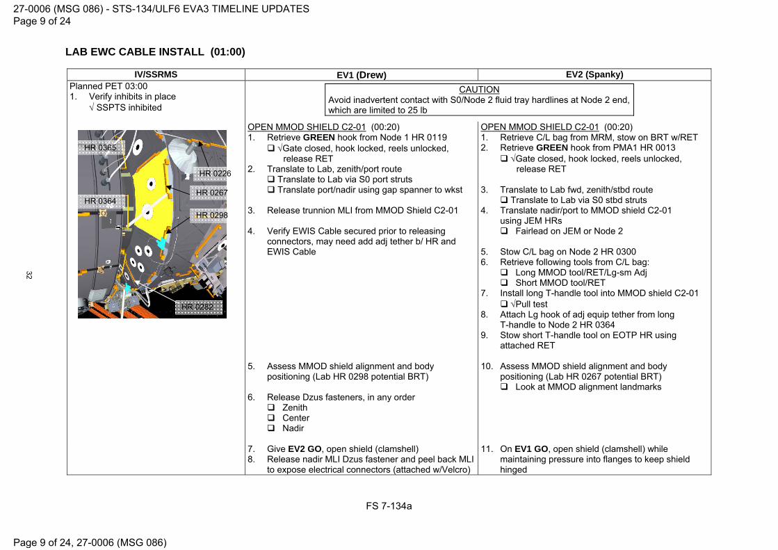
LAB EWC CABLE INSTALL (01:00)
FS 7-134a
IV/SSRMS EV1 (Drew) EV2 (Spanky) Planned PET 03:00 1. Verify inhibits in place SSPTS inhibited
CAUTION Avoid inadvertent contact with S0/Node 2 fluid tray hardlines at Node 2 end, which are limited to 25 lb
OPEN MMOD SHIELD C2-01 (00:20) 1. Retrieve GREEN hook from Node 1 HR 0119
Gate closed, hook locked, reels unlocked, release RET
2. Translate to Lab, zenith/port route Translate to Lab via S0 port struts Translate port/nadir using gap spanner to wkst 3. Release trunnion MLI from MMOD Shield C2-01 4. Verify EWIS Cable secured prior to releasing
connectors, may need add adj tether b/ HR and EWIS Cable
OPEN MMOD SHIELD C2-01 (00:20) 1. Retrieve C/L bag from MRM, stow on BRT w/RET 2. Retrieve GREEN hook from PMA1 HR 0013
Gate closed, hook locked, reels unlocked, release RET
3. Translate to Lab fwd, zenith/stbd route Translate to Lab via S0 stbd struts 4. Translate nadir/port to MMOD shield C2-01
using JEM HRs Fairlead on JEM or Node 2 5. Stow C/L bag on Node 2 HR 0300 6. Retrieve following tools from C/L bag:
Long MMOD tool/RET/Lg-sm Adj Short MMOD tool/RET
7. Install long T-handle tool into MMOD shield C2-01 Pull test
8. Attach Lg hook of adj equip tether from long T-handle to Node 2 HR 0364
9. Stow short T-handle tool on EOTP HR using attached RET
5. Assess MMOD shield alignment and body
positioning (Lab HR 0298 potential BRT) 6. Release Dzus fasteners, in any order
Zenith Center Nadir
10. Assess MMOD shield alignment and body positioning (Lab HR 0267 potential BRT) Look at MMOD alignment landmarks
7. Give EV2 GO, open shield (clamshell) 8. Release nadir MLI Dzus fastener and peel back MLI
to expose electrical connectors (attached w/Velcro)
11. On EV1 GO, open shield (clamshell) while maintaining pressure into flanges to keep shield hinged
HR 0226
HR 0298
HR 0282
HR 0365
HR 0364 HR 0267
27-0006 (MSG 086) - STS-134/ULF6 EVA3 TIMELINE UPDATES Page 9 of 24
Page 9 of 24, 27-0006 (MSG 086)
32

LAB EWC CABLE INSTALL (01:00) (Cont)
FS 7-134b
IV/SSRMS EV1 (Drew) EV2 (Spanky) NOTE
Once inhibits are in place, Station UHF will no longer be in the Big Loop. Comm with EV crew will be via Shuttle A/G1. Loss of comm is possible. Will verify comm after SSSR deactivated. If no comm, EV1 re-establish comm by moving to line of sight with Orbiter Antenna (ISS nadir). Will give GO for steps 9 thru 14. Then EV1 will re-establish comm before continuing with MMOD shield closure
2. Give MCC-H GO for SSSR (UHF) reconfiguration
MCC-H: Deactivate SSSR (UHF) 3. On MCC-H GO, A1R AUD CTR SL A/G1 – ON 4. Perform Comm Check
5. Give EV1 GO for EWIS connector ops
MATE P16A/J16A EWC CONNECTORS (00:15) 9. On IV GO, demate EWIS P16A from J16 (nadir most
on lab endcone) 10. Demate EWIS J16A from P16 (free-floating cable) 11. Remove old EWIS cable from under MMOD shield
and HR 12. Retrieve new EWC P16A and J16A cable,
route under HR 13. Mate connector P16A (90 backshell) to J16
(lab endcone) Good pins & EMI band; no FOD
14. Mate connector J16A to P16 (free-floating cable) Good pins & EMI band; no FOD
MATE P16A/J16A EWC CONNECTORS (00:15) 12. Assist EV1 as reqd with MMOD Shield
6. When J16A and P16A mated, give MCC-H GO to activate SSSR (UHF)
MCC-H: Activate SSSR (UHF) 7. On MCC-H GO,
A1R AUD CTR SL A/G1 – OFF NOTE
Big loop comm is via UHF
15. Stow/position cable so does not interfere with MMOD shield/MLI
16. WVS survey of connections under MLI
27-0006 (MSG 086) - STS-134/ULF6 EVA3 TIMELINE UPDATES Page 10 of 24
Page 10 of 24, 27-0006 (MSG 086)
33

LAB EWC CABLE INSTALL (01:00) (Cont)
FS 7-134c
IV/SSRMS EV1 (Drew) EV2 (Spanky)
CLOSE MMOD SHIELD C2-01 (00:15) 17. Reinstall MLI Dzus fastener Dzus alignment
Rotate ccw until Dzus drops down onto spring Rotate Dzus to locked position cw, quarter turn Verify all MLI is beneath Dzus fastener plates
18. Install MMOD shield C2-01 19. Engage Center Dzus fastener Dzus alignment
Rotate ccw until Dzus drops down onto spring Rotate Dzus to locked position cw, quarter turn
20. Engage Dzus fasteners ( Zenith, Nadir) Dzus alignment
Rotate ccw until Dzus drops down onto spring Rotate Dzus to locked position cw, quarter turn
CLOSE MMOD SHIELD C2-01 (00:15) 13. Assist EV1 as reqd
CLEANUP (00:10) 21. Mate new connector P1 to EWIS Ant 11
Good pins & EMI band; no FOD 22. Re-install gap spanner from Node 2 HR 0365 to
Lab HR 0267 (nadir stanchion) 23. RET to old EWIS cable and release all wire ties Stow any loose wire ties in trash bag
CLEANUP (00:10) 14. Install trunnion MLI over MMOD shield 15. Retrieve long T-handle tool/Lg-sm Adj/RET
from shield 16. Retrieve short T-handle tool from EOTP 17. Stow T-handles (2) in C/L bag
Short Long
8. Perform C/L bag inventory: Crewlock Bag Adj Equip Tether (Lg-sm) (ext) Wire Tie Caddy (Int RET) (2 long, 7 short) RET (sm-sm) PAMA Cheater Bar
24. Coil cable and use wire tie, if reqd 25. Stow EWIS cable in C/L bag
18. Perform C/L bag inventory 19. Wire tie P3/P4 cable to Lab HR 0268 and/or
HR 0267 (BRT wire tie)
Russian Ratchet Wrench (Int RET) RET (sm-sm) RET (sm-sm) Long T-Handle Tool Adj Equip Tether (Lg-sm) RET (sm-sm)
25a. Verify all cables are appropriately routed and wire tied to structure
26. WVS Survey
21. Verify all cables are appropriately routed and wire tied to structure
22. WVS Survey 23. Stow C/L Bag on BRT w/RET
Short T-Handle Tool Loop Pin Puller (Int RET) EWIS Cable
27. Glove Check
24. Glove Check 25. Translate to A/L, retrieve fairlead 26. Stow C/L bag near A/L
27-0006 (MSG 086) - STS-134/ULF6 EVA3 TIMELINE UPDATES Page 11 of 24
Page 11 of 24, 27-0006 (MSG 086)
34

NOD1/FGB CH 2/3 CABLE INSTALL (STBD) (01:05)
FS 7-136
IV/SSRMS EV1 (Drew) EV2 (Spanky) Planned PET 04:00 1. Verify inhibits in place: SSPTS Inhibited P19/P20/P21 Inhibited
CAUTIONAvoid inadvertent contact with PMA1 MDM and FGB Sun sensors. Ensure Safety Tethers are routed above all electrical connections
CH 2/3 CABLE INSTALL (STBD) (01:05)
1. Translate to Node 1 stbd 2. Retrieve GREEN hook from Node 1 HR 0119
Gate closed, hook locked, reels unlocked, release RET
3. Translate to FGB zenith, Node 3 Cable bag 4. Retrieve Stbd FGB Y-cable from bag (J20A)
RET to cable before releasing Velcro strap 5. Untwist taped wire tie to release cable bundles
CH 2/3 CABLE INSTALL (STBD) (01:05) 1. Translate to PMA1 nadir 2. Retrieve GREEN hook from PMA1 HR 0013
Gate closed, hook locked, reels unlocked, release RET
3. Translate to FGB zenith from stbd side
6. Transfer Node 1 fwd bundle (J138A) to EV2 7. Attach taped wire tie to PMA1 HR 0003 8. Retrieve nadir cable bundle (P669A) 9. Attach low profile wire tie to PMA1 HR 0001
4. Retrieve Node 1 fwd bundle (J138A) from EV1 CAUTION
Avoid inadvertent contact with WETA antenna on NOD1 and spare SASA hi-gain and lo-gain antennas on Z1 stbd
10. Translate to Node 1 aft/nadir while routing cable Fwd to Node 1 aft endcone Nadir using aft endcone HRs
11. Wire tie cable to Node 1 HR 0113 12. Demate P669 from Node 1 J669; do not mate P669A
P669 ←|→ NOD1 J669 13. Wire tie P669 and P669A connectors to Node 1 HR
0115
WARNING E/L HR 0537 has MMOD strike
5. Translate to Node 1 fwd endcone under Rat’s nest
while routing cable Fwd/stbd to Node 1 Fwd along E/L, over HPGTs Port onto Node 1 fwd endcone
HR 0115
HR 0107
P661 to J661 (NOD1 Port)
P669 to J669 (NOD1 Stbd)
NOD1 Aft/Nadir
27-0006 (MSG 086) - STS-134/ULF6 EVA3 TIMELINE UPDATES Page 12 of 24
Page 12 of 24, 27-0006 (MSG 086)
35

NOD1/FGB CH 2/3 CABLE INSTALL (STBD) (01:05) (Cont)
FS 7-137
IV/SSRMS EV1 (Drew) EV2 (Spanky)
14. Translate to PMA1/FGB zenith connector panel
NOTE Best worksite position is inverted; Right hand on connector, Left hand on tray
6. Demate W32B cable connector P138 from Node 1
J638; do not mate P138A W32B P138 ←|→ NOD1 J638
2. P669 demated P138 demated Give EV1 GO for demate of P19 and 20
15. On IV GO: Demate FGB P19 and P20 connectors from PMA1/FGB panel (zenith) FGB P19 ←|→ PMA1 J19 FGB P20 ←|→ PMA1 J20
16. Pull FGB P19 cable out from under SVS target
Release cable (P21/P20) as reqd from broom clip to provide additional slack
If need to demate P21, contact MCC-H 17. Remove cap from FGB Y-cable connector J20A 18. Mate stbd FGB cable connector J20A to FGB P20
Good pins & EMI band; no FOD FGB J20A →|← FGB P20
7. Remove cap from FGB cable connector J138A 8. Install cap on Node 1 J638 9. Stand by for IV GO on connector mating ops
3. P20A matedGive EV2 GO to mate J138A
19. Install cap on FGB J20 20. Route P19 cable port under FGB HR toward PDGF
(HR 1030) 21. Remove MLI cap from PDGF harness connector J19
(lanyarded) 22. Mate PDGF harness J19 to FGB P19
Good pins & EMI band; no FOD PDGF J19 →|← FGB P19
23. Move dust cover in place around mated connector; adjust wire tie as reqd Verify no metal portion of connectors is exposed
10. On IV GO: Mate FGB cable connector J138A to floating cable connector P138 Good pins & EMI band; no FOD FGB J138A →|← P138
11. Wire tie cable at following HRs as translate back to
PMA1: Node 1 HR 0130 (fwd/stbd – J138A wire tie) Node 1 HR 0122 (aft/stbd – low profile wire tie) (near Z1 pool handle)
Position cable so that it is as flush as possible to Node 1 stbd
Node 1 HR 0102 (low profile wire tie) PMA1 HR 0001 – any excess slack
W36B-P131 to J631 (NOD1 Port)
W32B-P138 to J638 (NOD1 Stbd)
NOD1 Fwd/Zenith
16 18 19 21
Broom Clip
17 20
fwd
stbdport
PDGF
Y-Cables
27-0006 (MSG 086) - STS-134/ULF6 EVA3 TIMELINE UPDATES Page 13 of 24
Page 13 of 24, 27-0006 (MSG 086)
36

NOD1/FGB CH 2/3 CABLE INSTALL (STBD) (01:05) (Cont)
FS 7-138
IV/SSRMS EV1 (Drew) EV2 (Spanky) 24. Retrieve caps from ORU bag Fish Stringer
25. Install caps on FGB J18 and J19
26. Translate nadir to Node 1 aft/nadir 27. Remove cap from FGB cable connector P669A 28. Install cap on floating cable connector P669 29. Mate FGB cable connector P669A to Node 1 J669
Good pins & EMI band; no FOD FGB P669A →|← NOD1 J669
4. On EV1 GO, give MCC-H GO to power up FGB Ch 2/3 and P19
30. Notify IV, complete with Ch 2/3 and FGB P19 connector ops
31. Wire tie cable at following HRs as translate back to PMA1: Node 1 HR 0113 (low profile wire tie)
32. Glove Check
(Translate to PAMA/PDGF – Cleanup and Photos)
12. Glove Check
(Translate to A/L – Tool Stow) (Translate to PAMA/PDGF – Cleanup)
27-0006 (MSG 086) - STS-134/ULF6 EVA3 TIMELINE UPDATES Page 14 of 24
Page 14 of 24, 27-0006 (MSG 086)
37

FGB AND PDGF PHOTOS/CLEANUP (00:15)
FS 7-139
IV/SSRMS EV1 (Drew) EV2 (Spanky) Planned PET 04:05
CAUTION Avoid inadvertent contact with grapple fixture shaft
PHOTOS/CLEANUP (00:15) 1. Translate to PAMA/PDGF, zenith PMA route 2. Time Permitting: Take photos of the following FGB
Thruster areas, as daylight and worksite access permit: Entire FGB port thruster cluster: Multiple angles Individual thrusters: Exterior cone Individual thrusters: Interior nozzle and throat
3. Time Permitting: Take photos of following PDGF
areas, as daylight and worksite access permit: PDGF worksite closeout Cable routing PDGF mating surface clearance
CLEANUP (00:15) 1. Translate to PAMA/PDGF, nadir PMA route 2. Inspect cabling around FGB PDGF; ensure cables
clear of mating interfaces and plane; use wire ties as reqd to secure cables in place
3. Wire tie any excess slack in any cabling 4. Retrieve grapple shaft cover/wire tie/RET from
PDGF; stow in Med ORU bag 5. Retrieve gap spanner; stow in Med ORU bag 6. Perform bag inventory of Med ORU bag 7. Stow Med ORU bag on BRT w/RET
1. Perform Med ORU bag inventory: (Ref FS 7-110 for Final Inventories)
4. Translate to FGB zenith 5. Close Node 3 Cable bag, stow on BRT w/RET 6. Translate to A/L 7. Open hatch thermal cover
8. Translate to A/L, nadir PMA route
8. Stow bags in A/L: Med ORU bag Node 3 Cable bag C/L bag
9. Transfer Med ORU bag to EV1 for A/L stow 10. Retrieve Tool Stow C/L bag 11. Stow C/L bag on BRT w/RET
(Stow EVA Camera - STP-H3 IR Imagery) (Translate to P3, Bay 20 – HPGT FRGF MLI Install)
27-0006 (MSG 086) - STS-134/ULF6 EVA3 TIMELINE UPDATES Page 15 of 24
Page 15 of 24, 27-0006 (MSG 086)
38

STP-H3 IR IMAGERY (00:40)
FS 7-139a
IV/SSRMS EV1 (Drew) Planned PET 05:20 1. Verify inhibits in place PSARJ locked
CAUTION
1. Avoid inadvertent contact with MHTEX radiator – Z93 paint 2. Top of STP-H3 is a 1 ft KOZ
NOTE Press and release for top function. Press and hold ~3 sec for bottom function.
NOTE IR Camera is set to auto stop a movie after 600 frames (10 mins).
VADER IR PHOTOS (00:40) 1. Stow EVA camera in A/L 2. Retrieve IR camera from A/L sw MASTER - ON, LED - Off 3. Verify SAFER config
L handle down (MAN ISOL Vlv – Open) R handle down (HCM – Closed)
4. Press and release ENABLE switch to initiate camera warmup (IV start 5 min timer) LED - On 5. Stow IR camera on BRT w/RET 6. Close hatch thermal cover 7. Translate to P1 Bay 18 – zenith route 8. Attach GREEN hook to P1 HR 3681
Gate closed, hook locked, reels unlocked, release RET 9. Translate to STP-H3 (outbd aft, zenith on ELC3) Stay 2’ away from TRRJ
NOTE Do not put excessive force in BRT when fully extended
10. Remove IR camera from BRT and stow it on swing arm 11. Position body with body along ELC, head ISS aft and BRT to STP-H3 FRAM HR (EV2 assist as reqd) 12. Remove display from camera 13. Remove camera lens cover
LSR S/T
E/M
F/A C/L
27-0006 (MSG 086) - STS-134/ULF6 EVA3 TIMELINE UPDATES Page 16 of 24
Page 16 of 24, 27-0006 (MSG 086)
39

STP-H3 IR IMAGERY (00:40)
FS 7-139b
IV/SSRMS EV1 (Drew) 14. Set camera focus on VADER zenith face using arrow keys (can be done during warm up): a. Right arrow Course Focus (+) b. Left arrow Course Focus (-) c. Up arrow Fine Focus (+) d. Down arrow Fine Focus (-) 15. After 5-min timer expires, perform Flat Field correction (Press and release F|A button) 16. Record 7 min video of VADER: a. Press and release the S|T button to start the video (frame countdown will start), notify MCC-H
MCC-H: Switch VADER to low emissivity MCC-H will transition VADER to low emissivity during video b. After 7 mins or on MCC-H Go, press and release the S|T button to stop the video (frame countdown will
stop) 17. Transfer movie to flash card (Press and hold S|T button for 3 sec. Expect 5-7 min to complete transfer) Transfer starts when ‘0% ready’ displays. Transfer complete when message goes away 18. Press and hold ENABLE switch for 5 sec to shut down camera LED - Off 19. Close lens cover
20. Stow display on the camera 21. Release BRT and relocate the IR camera to BRT w/RET 22. Translate to P1 HR 3681 23. Retrieve GREEN hook from P1 HR 3681
Gate closed, hook locked, reels unlocked, release RET 24. Glove Check
(Translate to A/L)
27-0006 (MSG 086) - STS-134/ULF6 EVA3 TIMELINE UPDATES Page 17 of 24
Page 17 of 24, 27-0006 (MSG 086)
40
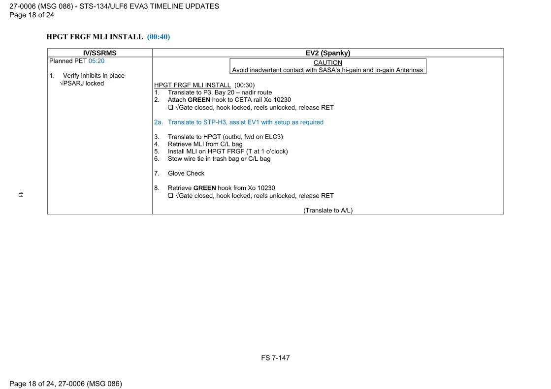
HPGT FRGF MLI INSTALL (00:40)
FS 7-147
IV/SSRMS EV2 (Spanky) Planned PET 05:20 1. Verify inhibits in place PSARJ locked
CAUTION
Avoid inadvertent contact with SASA’s hi-gain and lo-gain Antennas HPGT FRGF MLI INSTALL (00:30) 1. Translate to P3, Bay 20 – nadir route 2. Attach GREEN hook to CETA rail Xo 10230
Gate closed, hook locked, reels unlocked, release RET
2a. Translate to STP-H3, assist EV1 with setup as required 3. Translate to HPGT (outbd, fwd on ELC3) 4. Retrieve MLI from C/L bag 5. Install MLI on HPGT FRGF (T at 1 o’clock) 6. Stow wire tie in trash bag or C/L bag 7. Glove Check 8. Retrieve GREEN hook from Xo 10230 Gate closed, hook locked, reels unlocked, release RET
(Translate to A/L)
27-0006 (MSG 086) - STS-134/ULF6 EVA3 TIMELINE UPDATES Page 18 of 24
Page 18 of 24, 27-0006 (MSG 086)
41

EVA 3 CLEANUP/INGRESS (00:30)
FS 7-149
IV/SSRMS EV1 (Drew) EV2 (Spanky) Planned PET 06:00 1. Perform Tool and Bag Inventories:
(Ref FS 7- for Final Inventories)
CLEANUP (00:15) 1. Translate to A/L 2. Perform MWS tool inventory
CLEANUP (00:15) 1. Translate to A/L
Fairlead on Equip Lock HR 0500 2. Perform MWS tool inventory
2. Start Hatch Thermal Cover clock PET (30 min) __ : __
INGRESS (00:15)
INGRESS (00:15) 3. Open hatch thermal cover 4. Stow Tool Stow C/L bag and IR camera in A/L 5. Attach R Waist Tether to UIA D-ring
Gate closed, hook locked 6. Ingress A/L
3. Prior to hatch closure, perform WVS PWRDN (PHOTO/TV, WVS Cue Card)
3. On EV2 GO, RET to EV2 STP, release RED hook and attach to aft ext D-ring Gate closed, hook locked, reels unlocked,
release RET 4. Attach R Waist Tether to A/L int D-ring ext
Gate closed, hook locked 5. RET to STP, release RED hook and attach to
curved HR, fwd/stbd stanchion Gate closed, hook locked, reels unlocked,
release RET 6. Ingress A/L
7. Give EV1 GO to release EV2 RED hook
4. Stop Hatch Thermal Cover clock PET (30 min) __ : __
7. Close thermal cover; attach Velcro strap
8. Remove SCU from stowage pouch9. Remove DCM cover; Velcro to DCM 10. Connect SCU to DCM; SCU locked
NOTEA TCV setting 8 – Max C minimizes time for SCU cooling
8. Remove SCU from stowage pouch9. Remove DCM cover; Velcro to DCM 10. Connect SCU to DCM; SCU locked
NOTEA TCV setting 8 – Max C minimizes time for SCU cooling
11. WATER – OFF (fwd), expect H2O IS OFF msg 11. WATER – OFF (fwd), expect H2O IS OFF msg
CAUTIONDo not close hatch until EMU Water OFF for 2 min. Verify outer hatch clear of hardware
12. Verify outer hatch clear of hardware 13. Verify handle position per hatch decal 14. Close and lock hatch
Go to PRE-REPRESS (DEPRESS/REPRESS Cue Card) Go to PRE-REPRESS (DEPRESS/REPRESS Cue Card)
27-0006 (MSG 086) - STS-134/ULF6 EVA3 TIMELINE UPDATES Page 19 of 24
Page 19 of 24, 27-0006 (MSG 086)
42

27-0006 (MSG 086) - STS-134/ULF6 EVA3 TIMELINE UPDATES Page 20 of 24
Page 20 of 24, 27-0006 (MSG 086)
43
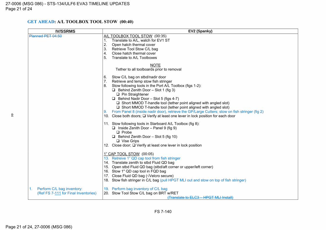
GET AHEAD: A/L TOOLBOX TOOL STOW (00:40)
FS 7-140
IV/SSRMS EV2 (Spanky) Planned PET 04:50
A/L TOOLBOX TOOL STOW (00:35) 1. Translate to A/L, watch for EV1 ST 2. Open hatch thermal cover 3. Retrieve Tool Stow C/L bag 4. Close hatch thermal cover 5. Translate to A/L Toolboxes
NOTETether to all toolboards prior to removal
6. Stow C/L bag on stbd/nadir door 7. Retrieve and temp stow fish stringer 8. Stow following tools in the Port A/L Toolbox (figs 1-2):
Behind Zenith Door – Slot 1 (fig 3) Pin Straightener
Behind Nadir Door – Slot 5 (figs 4-7) Short MMOD T-handle tool (tether point aligned with angled slot) Short MMOD T-handle tool (tether point aligned with angled slot)
9. From Panel 8 (inside nadir door), retrieve the GP/Large Cutters; stow on fish stringer (fig 2) 10. Close both doors; Verify at least one lever in lock position for each door 11. Stow following tools in Starboard A/L Toolbox (fig 8):
Inside Zenith Door – Panel 9 (fig 9) Probe
Behind Zenith Door – Slot 5 (fig 10) Vise Grips
12. Close door; Verify at least one lever in lock position
1” CAP TOOL STOW (00:05) 13. Retreive 1” QD cap tool from fish stringer 14. Translate zenith to stbd Fluid QD bag 15. Open stbd Fluid QD bag (stbd/aft corner or upper/left corner) 16. Stow 1" QD cap tool in FQD bag 17. Close Fluid QD bag (Velcro secure) 18. Stow fish stringer in C/L bag (pull HPGT MLI out and stow on top of fish stringer)
1. Perform C/L bag inventory: (Ref FS 7-111 for Final Inventories)
19. Perform bag inventory of C/L bag 20. Stow Tool Stow C/L bag on BRT w/RET
(Translate to ELC3 – HPGT MLI Install)
27-0006 (MSG 086) - STS-134/ULF6 EVA3 TIMELINE UPDATES Page 21 of 24
Page 21 of 24, 27-0006 (MSG 086)
44

27-0006 (MSG 086) - STS-134/ULF6 EVA3 TIMELINE UPDATES Page 22 of 24
Page 22 of 24, 27-0006 (MSG 086)
45

STP-H3 IR IMAGERY - TASK DATA
FS 7-170a
Estimated Task Duration: With RMS Without RMS
One EV Crew N/A 00:30
Two EV Crew N/A 00:30
Tools:
EV1
EVA IR Camera
Foot Restraints:
Task WIF APFR Setting
Contingency for VADER IR Imagery ELC3 WIF 3 [6,SS,F,12] APFR Note: If using the APFR on ELC3, there is the following constraint: While the second EVA crewmember is translating on the ELC3 structure, the first EVA crewmember in the APFR must maintain a handhold on approved ELC3 structure. This is to protect APFR hardware loads from exceeding the trip limit (ref EID684-14188).
Notes: 1. IR Camera is set to auto stop a movie after 600 frames (10 mins). 2. Do not put excessive force in BRT when fully extended
Cautions: 1. Avoid inadvertent contact with MHTEX radiator – Z93 paint 2. Top of STP-H3 is a 1 ft KOZ
Timeline Considerations:
1. EVA IR Camera must be in standby mode starting at Egress 2. EVA IR Camera needs 5 min to warm-up before use
27-0006 (MSG 086) - STS-134/ULF6 EVA3 TIMELINE UPDATES Page 23 of 24
Page 23 of 24, 27-0006 (MSG 086)
46
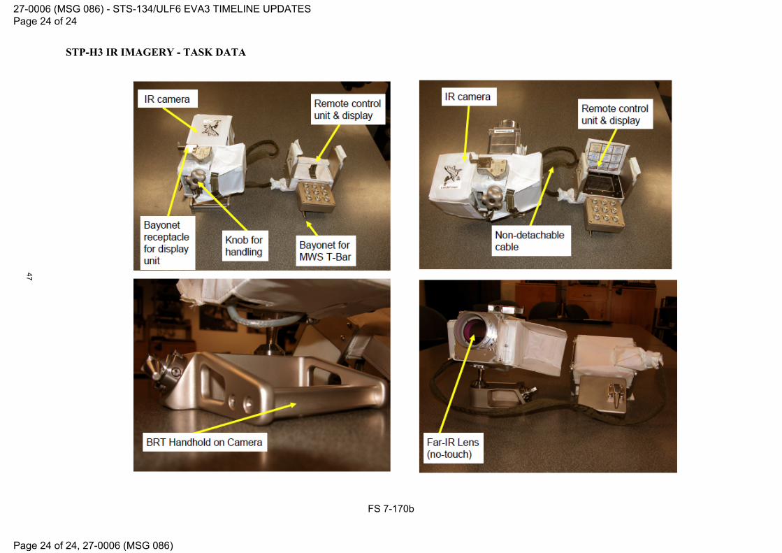
STP-H3 IR IMAGERY - TASK DATA
FS 7-170b
27-0006 (MSG 086) - STS-134/ULF6 EVA3 TIMELINE UPDATES Page 24 of 24
Page 24 of 24, 27-0006 (MSG 086)
47

27-0589A (MSG 088A): FD09 ULF6 SODF WARNING PCN INCORPORATION Page 1 of 2
23 MAY 11
DURATION: 2 hours INSTRUCTIONS: Gather ‘Warning PCNs’ Ziplock from the half CTB located on LAB1P6 rack front. Warning PCN Incorporation In the LAB:
Retrieve Warning Procedures Book (Cover Date: 15 FEB 2011) ___________ Gather Warning PCN [Qty:1] from ‘Warning PCNs’ Ziplock Replace cover Replace pages 675 thru 680 Replace pages 717 thru 770 Replace pages 803 thru 832; add 832a and 832b Replace pages 907 thru 938 Replace pages 945 thru 972; add 972a and 972b Replace pages 1037 and 1038 Place discarded cover and pages in the ISS common trash Stow Warning Procedures Book (New Cover Date: 25 MAR 2011) ___________
In the SM: Retrieve Warning Procedures Book (Cover Date: 15 FEB 2011) ___________
Gather Warning PCN [Qty:1] from ‘Warning PCNs’ Ziplock Replace cover Replace pages 675 thru 680 Replace pages 717 thru 770 Replace pages 803 thru 832; add 832a and 832b Replace pages 907 thru 938 Replace pages 945 thru 972; add 972a and 972b Replace pages 1037 and 1038 Place discarded cover and pages in the ISS common trash Stow Warning Procedures Book (New Cover Date: 25 MAR 2011) ___________
In the FGB: Retrieve Warning Procedures Book (Cover Date: 15 FEB 2011) ___________
Gather Warning PCN [Qty:1] from ‘Warning PCNs’ Ziplock Replace cover Replace pages 675 thru 680 Replace pages 717 thru 770 Replace pages 803 thru 832; add 832a and 832b Replace pages 907 thru 938 Replace pages 945 thru 972; add 972a and 972b Replace pages 1037 and 1038 Place discarded cover and pages in the ISS common trash Stow Warning Procedures Book (New Cover Date: 25 MAR 2011) ___________
NOTE Green rings on PCNs were for ease during shipment. Stow rings per crew preference.
48

27-0589A (MSG 088A): FD09 ULF6 SODF WARNING PCN INCORPORATION Page 2 of 2
23 MAY 11
Ammonia Detection Kit Updates Gather Ammonia Detection Kit Cue Card #1 [QTY:2] and procedure 2.836 IFHX NH3 LEAK DETECTED – WARN [QTY:2] from ‘Warning PCNs’ Ziplock In the FGB: Kit # 1, behind FGB panel 308
Replace 1 copy each of Ammonia Detection Kit Cue Card #1 and procedure 2.836 IFHX NH3 LEAK DETECTED – WARN ___________
In the MRM2: Kit # 2, visible crew preference location
Replace 1 copy each of Ammonia Detection Kit Cue Card #1 and procedure 2.836 IFHX NH3 LEAK DETECTED – WARN ___________
Place discarded cue cards and pages in the ISS common trash Report completion to MCC-H.
49

28-0012 (MSG 089) BRT BALLSTACK STIFFNESS ADJUSTMENT Page 1 of 5 pages
23 MAY 11
OBJECTIVE: Adjust Body Restraint Tether (BRT) ball stack stiffness. DURATION: 30 minutes to adjust cable tension and re-install screws. MATERIALS: Ziploc Bag Kapton Tape (if required per step 1.11) TOOLS: ISS IVA Toolbox: Drawer 2:
Ratchet, 1/4" Drive 1/4” to 3/8” Adapter
(5-35 in-lbs) Torq Driver, 1/4" Drive Drawer 3: 4-1/32" Long, #2 Phillips, 3/8" Drive
Figure 1. – Location of BRT Fasteners. (Configuration Shown for Reference Only)
Base mount screws (four, 90° apart, offset, non-captive)
Viewing Direction
Base Mount Debris Sleeve Fastener
Rigidizing Collar
50

28-0012 (MSG 089) BRT BALLSTACK STIFFNESS ADJUSTMENT Page 2 of 5 pages
23 MAY 11
1. BALL STACK STIFFNESS ADJUSTMENT
WARNING
A locking feature in the base mount screws will result in a high breaking torque (up to 40 in-lbs) during removal. This may result in tool slippage and personal injury.
NOTE
Removal of 4 screws will allow separation of base mount assembly from ball stack. If separation occurs, reassemble.
1.1 Call down Serial Number of BRT being adjusted. (Serial Number is located on
Debris Sleeve)
1.2 Remove non-captive base mount screws (four) (Ratchet, ¼” Drive; 1/4” to 3/8” Adapter; #2 Phillips, 3/8" Drive). Refer to Figure 2. Stow non-captive screws (Ziploc Bag).
Figure 2. - Release Base Mount Screws.
1.3 Extend BRT to maximum length and ensure rigidizing collar is fully rigidized
(tightened).
Screwdriver for demonstration only
51

28-0012 (MSG 089) BRT BALLSTACK STIFFNESS ADJUSTMENT Page 3 of 5 pages
23 MAY 11
1.4 While grasping ball stack in area of debris sleeve fasteners (Refer to Figure 3), maintain slight inward force and rotate base mount assembly 180° counter-clockwise relative to ball stack (Ref Figure 1 and 3, viewing direction) until screw holes are aligned. (Total number of CCW turns is recorded below in step 1.7.)
NOTE
If base mount assembly cannot be rotated by hand, no other adjustment method is available, and should not be attempted. Proceed to 1.9.
Figure 3. - Rotate Base Mount Assembly
Counter Clockwise 180° CCW.
1.5 Check ball stack for desired stiffness.
1.6 Repeat step 1.4 until desired stiffness is achieved. If desired stiffness cannot be obtained, proceed to 1.9.
1.7 Loosen rigidizing collar and verify that minimum stiffness is acceptable.
Record total number of CCW turns of base mount assembly: _________
1.8 If too stiff, rotate base mount assembly clockwise and test until stiffnesses are balanced (user preference).
Record number of CW turns of base mount assembly, if required: __________ (Step is reverse process of 1.4 to 1.5.)
NOTE
The locking feature in the base mount should prevent full insertion of the non-captive screws.
1.9 Align holes in ball stack and base mount and re-install base mount screws (four)
finger tight. Refer to Figure 4. If any screw can be completely installed just by finger tightening, report to MCC-
H that locking feature is non-functional.
Rotate base mount into the page
Viewing Direction
52

28-0012 (MSG 089) BRT BALLSTACK STIFFNESS ADJUSTMENT Page 4 of 5 pages
23 MAY 11
Figure 4. - Initial Screw Installation, Finger Tight.
1.10 In either case, complete installation of screws. Tighten, torque to 35 in-
lbs.(Ratchet, 1/4” Drive; (5-35 in-lbs) Torq Driver, ¼” Drive; 1/4” to 3/8”Adapter; #2 Phillips, 3/8" Drive).
1.11 Inspect screw heads for sharp edges. If found, wrap with 2 layers of Kapton
tape. Refer to Figure 5.
Figure 5. - Kapton Tape Installation.
1.12 Verify that seam in debris sleeve is straight.
Refer to Figure 6.
Kapton Tape Wrap
53

28-0012 (MSG 089) BRT BALLSTACK STIFFNESS ADJUSTMENT Page 5 of 5 pages
23 MAY 11
Figure 6. - Seam Alignment.
1.13 Perform functional stiffness test with assembled BRT at maximum length.
Extend BRT to maximum length and fully rigidize collar (tightened). Check ballstack for proper operation.
1.14 Report completion to MCC-H.
Note: Picture is of NBL unit, seam on Flight unit is not velcro.
54

MSG 093: STORRM CABLE TROUBLESHOOTING
END OF PAGE 1 OF 1, MSG 093
1.0 HARDWARE CONNECTION 1 PGSC 1.1 √All four legs of STORRM RS-422 DATA cable connected to PCMCIA 2
card dongles 3 1.2 If cable(s) loose/disconnected 4
Reconnect cable(s) 5
1.3 √Both PCMCIA cards firmly seated 6 If one or both PCMCIA cards loose/disconnected 7
Reseat PCMCIA card(s) 8 1.4 √RJ-45 Ethernet cable 9
If cable is loose/disconnected 10 Reconnect cable 11
STORRM AP 1.5 √All four LAN connectors. Gently pull to determine quality of connection 12 then reconnect each of the four cables verifying engagement of 13 connector. 14 15 The ports and cables should be matched up as follows: 16
LAN1= DRU1 17 LAN2= DRU3 18 LAN3= STORRM PGSC 19 LAN4 = PGSC WAP 20
21
1.6 Notify MCC-H, number and name of any off-nominal connection. 22 23 24
25
26
27
28
29
30
31
32
33
34
35
36
37
38
39
40
41
42
43
44
45
55

MSG 094 - EVA Camera Power Switch Mod
END OF PAGE 1 OF 1, MSG 094
Preventing Manipulation of EVA CAMERA Power Switch 1 2 3 Background: During EVA 2 it was reported that one camera would not work. After the EVA 4 it was found that the power switch had been turned to the OFF position after egress. 5 6 Workaround: In order to ensure that the EVA Camera ON/OFF switch cannot be 7 manipulated after the EVA Camera Blanket is installed, an additional step is being added 8 to the execution note of the ISS activity P/TV EVA CAMR TRNARD to tape the ON/OFF 9 switch with Kapton tape. 10 11 12 13 14 15 16 17 18 19 20 21 22 23 24 25 26 27 28 29 30 31 32 33 34 35 36 37 38 39 40 41 42 43 44 45 46 47 48 49 50
56

MSG 095 - EVA 3 IR CAMERA FOR VADER IMAGRY
END OF PAGE 1 OF 3, MSG 095
OBJECTIVE: 1 Assembly of the EVA IR Camera and thermal data collection of the VADER payload. 2 3
Table 1. Parts 4
Nomenclature Part No. EVA IR Camera 1257950-701
EHIP Battery Pack SEG39130223-303
Compact Flash Card SDCFBI-1024-201-00
Compact Flash to PCMCIA Adaptor SDZ12100650-301
5 1. LOCATING THE EVA IR CAMERA AND THE EHIP BATTERY 6
1.1 Locate the EVA IR Camera at NOD104_A2 (in 0.5 CTB, barcode 7 006590J, s/n 1141). 8
9 1.2 Obtain the EHIP Battery Pack, s/n 1029 from EVA #3 Systems mesh 10
bag. 11 12 2. CONFIGURING EVA IR CAMERA FOR OPERATIONS 13 2.1 Install EHIP Battery Pack. 14 15
2.2 Compact Flash Card installed 16 17 2.3 Close right side thermal cover. 18 19 2.4 Lens Cover – Fold to left side 20 21
2.5 sw MASTER ON (Wait 30 seconds for initialization.) 22 If 'Level/Span: Manual' or 'Manual' displayed in top left of LCD: 23
2.6 pb E/M Press, hold (to activate menu) 24 25
2.7 sel 'Image' – 'Continuous adjust' [pb E/M Press (to 26 select)] 27
28
2.8 'Level/Span: Manual' or 'Manual' not displayed in top left of 29 LCD 30
31
2.9 Date/Time set to GMT (lower left of LCD) 32 If Date/Time incorrect: 33
2.10 pb E/M Press, hold (to activate menu) 34 35
2.11 sel 'Setup' – 'Other settings' [pb E/M Press (to select)] 36 37
2.12 sel 'Date/time' [pb E/M Press (to select)] 38 39
2.13 sel desired field [pb Up/Down Arrow Press (to set GMT)] 40 41 42
~
57

MSG 095 - EVA 3 IR CAMERA FOR VADER IMAGRY
END OF PAGE 2 OF 3, MSG 095
2.14 sel desired settings [pb Left/Right Arrow Press (to set 1 GMT)] 2
3
2.15 pb E/M Press 4 5 2.16 Set Burst and Frame Rate 6
2.16.1 pb E/M Press, hold (to activate menu) 7 8
2.16.2 sel 'File' – 'Burst Setup' [pb E/M Press (to select)] 9 10
2.16.3 'Max #Frames' – '600' [pb Left/Right Arrow Press (to 11 select)] 12 13 2.16.4 'Save every' – '60', 'Frame' [pb Left/Right Arrow (to select)] 14 15
NOTE 'FPS' and 'Elapse Time' determined by 'Max #Frames' and 'Save Every' settings.
16
2.16.5 'FPS' – '1.0' 17 18
2.16.6 'Elapse Time' – '600' 19 20
2.16.7 pb E/M Press 21 22 2.17 Clear Compact Flash Card 23
2.17.1 pb E/M Press, hold (to activate menu) 24 25
2.17.2 sel 'File' – 'Images…' [pb E/M Press to select)] 26 27
2.17.3 pb E/M Press, hold (to activate menu) 28 29
2.17.4 sel 'Delete all images' [pb E/M Press (to select)] 30 31
2.17.5 sel 'Delete' (Press E/M to select) 32 33
2.17.6 'No image saved' 34 35
2.17.7 pb C/L Press 36 37
2.18 Camera Powerdown 38
2.18.1 sw ENABLE Up (hold for 5 seconds) 39 40 2.18.2 Lens Cover – Reinstall 41 42
2.18.3 sw MASTER Off 43 44
The Camera is now ready for the EVA timeline. 45 46 47 48
~
58

MSG 095 - EVA 3 IR CAMERA FOR VADER IMAGRY
END OF PAGE 3 OF 3, MSG 095
3. IMAGE DOWNLINK 1
3.1 sw MASTER – Off 2 3 3.2 Remove Compact Flash Card from the EVA IR Camera. 4 5 3.3 On any networked ISS SSC, copy files to C:\Images for downlink. 6 7
3.4 Notify MCC-H which ISS SSC the IR imagery was transferred to. 8 9 3.5 When transfer to ISS SSC complete, install the Compact Flash Card 10
back into the EVA IR Camera. 11 12 4. DEACTIVATION 13
EVA IR Camera 14 15
4.1 Lens Cover – Installed 16 17 4.2 Remove EHIP Battery Pack. 18 19 4.3 Stow EHIP Battery Pack in A/L1O1 in M02 bag s/n 1038. 20 21 4.4 Stow EVA IR Camera in the 0.5 CTB barcode 006590J, s/n 1141. 22 23 4.5 Stow the 0.5 CTB in NOD1O4_A2. 24 25
26 27 28 29 30 31 32 33 34 35 36 37 38 39 40 41 42 43 44 45 46 47 48 49 50
59

MSG 096 - ULF6 FD9 STOWAGE NOTES
END OF PAGE 1 OF 6, MSG 096
1
2
BATT-INSTL (MS1, MS3) - 144/03:16
# Location Item Name P/N S/N B/C Notes
Type: Standard
1 NOD1_Deployed Mesh Bag: EVA 3
Systems
LiOH Cartridge Canister [Qty: 2] MC621-0008-
0409/SV755510-4Any Any REPORT S/Ns to MCC-H
2 EMU Li-Ion Battery SV1014881-00-003004 3005
00133625J 00133626J
3 EMU 3004 Aft EDDA
LiOH Cartridge Canister MC621-0008-
0409/SV755510-42016
used during EVA 2
4 EMU 3018 Fwd EDDA
LiOH Cartridge Canister MC621-0008-
0409/SV755510-42030
used during EVA 2
Type: Restow
5 EMU 3004 Aft EDDA
LiOH Cartridge Canister MC621-0008-
0409/SV755510-4Any
Report s/n to MCC-H
6 EMU Li-Ion Battery SV1014881-00-00 3004 00133625J
7 EMU 3018 Fwd EDDA
LiOH Cartridge Canister MC621-0008-
0409/SV755510-4Any
Report S/N to MCC-H
8 EMU Li-Ion Battery SV1014881-00-00 3005 00133626J
9 SYSTEMS
TRANSFER Bag
LiOH Cartridge Canister MC621-0008-
0409/SV755510-42016
10 LiOH Cartridge Canister MC621-0008-
0409/SV755510-42030
60

MSG 096 - ULF6 FD9 STOWAGE NOTES
END OF PAGE 2 OF 6, MSG 096
CDRA-REAR-UTILITIES (CDR,FE-3) - 144/03:41
# Location Item Name P/N S/N B/C Notes
Type: Standard
1
Crew Preference
Kapton Tape
2 Dry Wipes
3 Gray Tape
4 Ziplock Bag
5 Velcro Strap
6 NOD1D4_G2 Drawer 2
Drawer 2, S/N 1003
Ratchet, 1/4" Drive SKG33117562-939
7 5/32" Hex Head, 1/4" Drive SKG33117562-742
8
NOD1D4_G2 Drawer 5
Drawer 5, S/N 1003
Static Wrist Tether SKG33117562-335
61
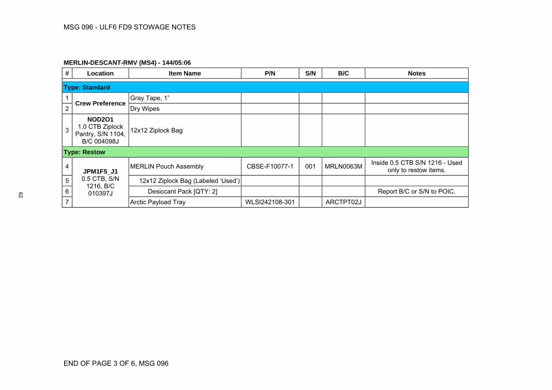
MSG 096 - ULF6 FD9 STOWAGE NOTES
END OF PAGE 3 OF 6, MSG 096
MERLIN-DESCANT-RMV (MS4) - 144/05:06
# Location Item Name P/N S/N B/C Notes
Type: Standard
1 Crew Preference
Gray Tape, 1”
2 Dry Wipes
3
NOD2O1 1.0 CTB Ziplock
Pantry, S/N 1104, B/C 004098J
12x12 Ziplock Bag
Type: Restow
4 JPM1F5_J1 0.5 CTB, S/N
1216, B/C 010397J
MERLIN Pouch Assembly CBSE-F10077-1 001 MRLN0063M Inside 0.5 CTB S/N 1216 - Used
only to restow items.
5 12x12 Ziplock Bag (Labeled ‘Used’)
6 Desiccant Pack [QTY: 2] Report B/C or S/N to POIC.
7 Arctic Payload Tray WLSI242108-301 ARCTPT02J
62

MSG 096 - ULF6 FD9 STOWAGE NOTES
END OF PAGE 4 OF 6, MSG 096
OGS-QD-MATE (MS1) - 144/07:16
# Location Item Name P/N S/N B/C Notes
Type: Standard
1
NOD1D4_K2 FFTD & Gamah
Seal Maintenance Kit, S/N 1001
Brass Pick
Only required if contaminants found in Oxygen QDs
2
Crew Pref
Ziplock Bags
3 Velcro Ties
4 Scissors
5
NOD1O4_C1 0.5 CTB: Rubber
Gloves, S/N 1159, B/C 006608J
Clean Room Gloves SEG33116979-301
Type: Restow
6 PMM1S3_B1 0.5 CTB: OGS Hardware, S/N
1349, B/C 010530J
Ziplock of H2 Sensor ORU Caps OGS Caps
7 1/2" QD Caps [QTY:2] SV825483-5
63

MSG 096 - ULF6 FD9 STOWAGE NOTES
END OF PAGE 5 OF 6, MSG 096
GREASE GUN CLEANUP (MS3) - 144/07:46
# Location Item Name P/N S/N B/C Notes
Type: Standard
1
A/L1 Deployed
Straight Nozzle Grease Gun Assy SED33120736-3051004 1007
Used during EVA 2
2 J-hook Nozzle Grease Gun Assy SEG33120736-3061002 1005
used during EVA 2
3 NOD2O1
Ziplock Pantry Large Ziploc (24" x 24") Ziploc
Qty Four
Type: Restow
4 A/L1 Deployed "Done Tools"
Mesh Bag
Straight Nozzle Grease Gun Assy SED33120736-3051004 1007
each gun in individual bag
5 J-hook Nozzle Grease Gun Assy SEG33120736-3061002 1005
each gun in individual bag
OGS-RACK-ACCESS (MS4) - 144/07:56
# Location Item Name P/N S/N B/C Notes
Type: Standard
1 A/L1_Deployed CSA-O2 [Qty. 2] SED46115801-3051045 1046
00127914J 00054324J
2 NOD1D4_G2 Drawer 2
Ratchet, 1/4" Drive SKG33117562-939
3 5/32" Hex Head, 1/4" Drive SKG33117562-742
64

MSG 096 - ULF6 FD9 STOWAGE NOTES
END OF PAGE 6 OF 6, MSG 096
OGS-CONT-INSTALL (MS1, MS4) - 144/08:41
# Location Item Name P/N S/N B/C Notes
Type: Standard
1 Temp stowed from OGS-QD-
MOD on GMT 141
OGA Filter to HX Jumper Assy SEG33123138-301 Jumper with modified QD
2 1/4" QD 502060-1191
Removed from OGA Filter to HX Jumper
3
PMM1S3_C1 1.0 CTB, S/N
1291, B/C 010627J
OGA Pump to ACTEX Jumper SV825600CT014 01 00142435J
4 Silver Removal Cartridge SEG11100313-311 2002 00140412J
5 OGA Remediation Adapter SEG33122706-302 1001 00146236J Mated to Silver Removal Cartridge
for thermal compliance.
6 30cc Syringe SEG46121619-301
Labeled "THERMAL". Mated to Silver Removal Cartridge for
thermal compliance.
7 JPM1F6_A1 0.5 CTB, S/N
1021, B/C 002861J, "LAB-A/L ISL H/W"
Large Ziplock
8 8" Wire Tie T30M2HALC2
If required to secure remediation hardware inside OGS rack per step
6.
9 ISS IVA Toolbox
Ratchet, 1/4" Drive SKG33117562-939
10 5/32" Hex Head, 1/4" Drive SKG33117562-742
Type: Restow
11 PMM1S3_C1 1.0 CTB, S/N
1291, B/C 010627J
30cc Syringe SEG46121619-301
Labeled "THERMAL." Removed from Silver Removal Cartridge.
12 OGA Remediation Adapter SEG33122706-302 1001 00146236J
13 1/4" QD 502060-1191 1001 00146236J Mated to OGA Remediation Adapter to provide thermal
compliance during stowage.
1 2 3
65

28-0013 (MSG 097) - Node 3 CDRA Bed 201 R&R Big Picture Words Page 1 of 3
Page 1 of 3, 28-0013 (MSG 097)
Node 3 CDRA Bed 201 R&R Big Picture Words 1
2 BACKGROUND: 3 The main objective for the CDRA maintenance on ULF6 is to remove the Node 3 CDRA Bed 4 201 and stow it for return to Earth on the shuttle. Bed 201 is commonly referred to as “the 5 back bed”. A replacement bed flew on ULF-6, and will be installed in the bed 201 location, 6 but removing the currently installed bed for return is the main objective. 7 8 PROCEDURES: 9 27-0387 CDRA Desiccant/Sorbent Bed 201 (NOD3A4 ARS Rack) - Hardcopy on Shuttle - 10 Book: ISS CDRA stowed at MF71G 11 25-0311 CDRA Desiccant/Sorbent Bed 201 R&R NOD3A4 - Appendix - Hardcopy on 12 Shuttle - Book: ISS CDRA stowed at MF71G 13 25-0315 Node 3 (AR2) CDRA Stowage Configuration 14 15 27-0387 CDRA Desiccant/Sorbent Bed 201 (NOD3A4 ARS Rack) was written with the 16 understanding that it would be executed in three parts during the ULF-5 mission. However, 17 the task may be divided into more parts, so please focus on the steps called out in execute 18 notes rather than relying on the procedure to tell you when to start and stop an activity. 19 20 ACTIVITY OVERVIEW: 21 22 Activity Description: Kabin Removal 23 Procedure: 27-0387 CDRA Desiccant/Sorbent Bed 201 (NOD3A4 ARS Rack) step 1 24 Details: Kabin Removal is listed in the procedure as an “if required” step. During ULF5, the 25 crew was able to rotate the AR Rack down partially to manipulate the CDRA rear 26 connections, without removing the Kabin. They also verified that it is possible to remove the 27 CDRA frame from the front of the AR rack without removing Kabin. So, we do not believe 28 that you will have to remove the Kabin, but left the step in incase you needed more access. 29 If you do happen to remove the Kabin, a step to replace it when you are complete is at the 30 end of the procedure (step 27). 31 32 Activity Description: CDRA Frame Prep for Removal 33 Procedure: 27-0387 CDRA Desiccant/Sorbent Bed 201 (NOD3A4 ARS Rack) steps 2-6 34 Details: Disconnect the CDRA main power/data and fluid utilities. This activity requires 35 rack rotation. Before rotating the AR rack, the Vacuum line must be demated. If not 36 demated, the umbilical may incur damage due to the rotation. This demate is incorporated 37 in your procedure. After rotating the rack down, you will remove the rack rear access panel 38 and demate several power/data connections, Fluid QDs and hydraflow couplings. 39 40 A few things to remember about Hydraflow fittings: 41 Hold the male side steady and turn the female side. The two o-rings making a good seal in 42 the connection are under the male side of the fitting. This makes it very hard to turn the 43 male fitting and you risk damage to the o-rings. (We do have spares on board, if required). 44 The fittings are meant to be hand-tight and should not require tools. For a better grip, we 45 recommend deerskin gloves or an exercise band. Tools may deform the hydraflow 46 couplings and make it increasingly harder to mate/demate the connections. 47 48
66

28-0013 (MSG 097) - Node 3 CDRA Bed 201 R&R Big Picture Words Page 2 of 3
Page 2 of 3, 28-0013 (MSG 097)
As you demate connections, you will place a ziplock back and secure with Kapton tape over 1 the open fittings to prevent FOD introduction in to the system. For the power/data and 2 hydraflow connections, kapton tape alone is acceptable. 3 4 Activity Description: CDRA Frame Removal 5 Procedure: 27-0387 CDRA Desiccant/Sorbent Bed 201 (NOD3A4 ARS Rack) steps 8-10 6 Details: There are two bolts used as a grounding path for the CDRA that are securing the 7 frame in place. To remove these bolts, you will partially rotate the rack and remove the side 8 access panel. Once the bolts are removed, the rack is rotated up and CDRA is removed 9 through the front right access door of the AR rack. You may use the Wireway/Coldplate 10 Covers (AKA cookie sheets) to help you in sliding the CDRA out. There are two star blocks 11 in step 9 that have additional access steps if you need them. One is to remove a grounding 12 wire from the rack faceplate and the other is to remove some insulation from a selector valve 13 that may or may not cause interference with the rack structure. Also, the seat track buttons 14 on the CDRA Bed are only 8” apart and do not accommodate the installation of an 8.5” 15 Handrail. However, if you need a translation aid, you can install one side of the handrail and 16 use it that way. Other crews have also installed Seat Track Stud Rings on each of the 17 buttons and used those to help pull the CDRA out. Either way, an aid has been helpful to 18 crews in the past, as it does require a good amount of force to pull the CDRA frame out. 19 20 Activity Description: CDRA Tie-Down in JPM 21 Procedure: 25-0315 Node 3 (AR2) CDRA Stowage Configuration 22 Details: Procedure contains specific steps to tie down the CDRA frame for stowage in the 23 JPM. This will also be where you perform the work to remove the CDRA Bed 201 for return. 24 25 Activity Description: CDRA Component Group Removal 26 Procedure: 27-0387 CDRA Desiccant/Sorbent Bed 201 (NOD3A4 ARS Rack) steps 11-14 27 Details: To access the CDRA Bed 201 for removal, you must first remove all the 28 components from the CDRA frame (ducting, blower/precooler, Selector Valves, etc). These 29 components come off in 3 groups. They have been color coded in the procedure and 30 appendix to help with the removal. It is important to keep the component groups together, 31 as they will go back on as groups too. During the removal of the component groups, you will 32 encounter several conical filters (AKA sock filters). The following note is in the procedure: 33 34 NOTE 35 Sock Filters have been installed to prevent Zeolite Debris from 36 damaging CDRA pump and Selector Valves. Filters are delicate cone 37 screens fitted inside the Hydraflow coupling. There are six total Filters, 38 four will be exposed during this maintenance procedure and 1 will NOT 39 be re-installed once removed. 40 1. CDRA Bed 201 Filter (1.5" diameter, 8" long) - Leave out 41 2. CDRA Pump Filter (0.5" diameter, 1.5" long) - Re-install 42 3. CDRA Valve 104 Filter (0.5" diameter, 1.5" long) - Re-install 43 4. CDRA Valve 103 Filter (1.5" diameter, 3" long) - Re-install 44 45 During the development of the ULF6 timeline, it was determined that TWO of these filters 46 should not be re-installed. Per the execute notes for this activity, you will NOT re-install: 47 48 1. CDRA Bed 201 Filter (1.5" diameter, 8" long) - Leave out 49
67

28-0013 (MSG 097) - Node 3 CDRA Bed 201 R&R Big Picture Words Page 3 of 3
Page 3 of 3, 28-0013 (MSG 097)
4. CDRA Valve 103 Filter (1.5" diameter, 3" long) - Re-install LEAVE OUT 1 2 This basically means, leave out all 1.5” diameter filters. The procedure has you create a 3 ziplock bag for the filters that will not be reinstalled. Your stowage note will tell you where to 4 restow these. The other two filters should be treated as part of their respective component 5 groups and stowed for later re-installation. 6 7 Activity Description: CDRA Bed 201 R&R 8 Procedure: 27-0387 CDRA Desiccant/Sorbent Bed 201 (NOD3A4 ARS Rack) steps 15-16 9 Details: The CDRA Desiccant/Sorbent Bed 201 has two electrical/data connections, four 10 bolts and four pin assemblies. The pin assemblies are at the top of the CDRA Bed and 11 serve as alignment guides for installation. Each pin assembly has 3 fasteners. These pin 12 assembly fasteners have been known to become non-captive. Also, the CDRA Bed is 13 covered in insulation. This insulation is plyable and can be pushed or deformed in order to 14 remove or replace the CDRA Bed. 15 16 Activity Description: CDRA Component Group Replace 17 Procedure: 27-0387 CDRA Desiccant/Sorbent Bed 201 (NOD3A4 ARS Rack) steps 17-21 18 Details: Component groups will be replaced in the reverse order in which they were 19 removed. So, you will start replacement with Component Group 3. As listed in the details 20 above about CDRA Filters, you will only be replacing the 0.5” diameter filters (Qty 2) during 21 the component group replacement. This is a change from what is written in the procedure. 22 This will also be outlined in the execute notes for this activity. Step 18 was written 23 specifically on how to install the CDRA Valve 103 Filter. You will now only use that step to 24 replace the ducting instead of the ducting and filter. 25 26 Activity Description: CDRA Frame Replacement 27 Procedure: 27-0387 CDRA Desiccant/Sorbent Bed 201 (NOD3A4 ARS Rack) step 22 28 Details: You will be installing the CDRA Frame in to the rack through the front access 29 panel. Some crews have found that partially through the installation, they need to rotate the 30 rack down to verify no cables or fluid lines are being caught. This is perfectly fine, but may 31 require a Kabin Removal. Also, the last few inches have been known to be a little sticky. 32 Once you’ve verified that no cables or fluid lines are preventing installation, the last few 33 inches may require a more substantial “shove” than you might expect. 34 35 Activity Description: Mating CDRA Utilities 36 Procedure: 27-0387 CDRA Desiccant/Sorbent Bed 201 (NOD3A4 ARS Rack) steps 23-26 37 Details: Most CDRA Utilities are located at the back of the rack. For this activity, you will 38 be rotating down and mating those utilities. You will start with the power/data utilities. Once 39 those are mated, you will pause while the ground verifies that the CDRA responds to 40 commanding. Then, when you get the thumbs up, you’ll proceed on to remate all the fluid 41 QDs and hydraflow fittings. Once that is complete, you will close out the rear of the rack and 42 rotate up. At this point, you’ll remate a few connections at the rack UIP and then report to 43 MCC that the CDRA is ready for activation! 44 45 46 47 48 49
68
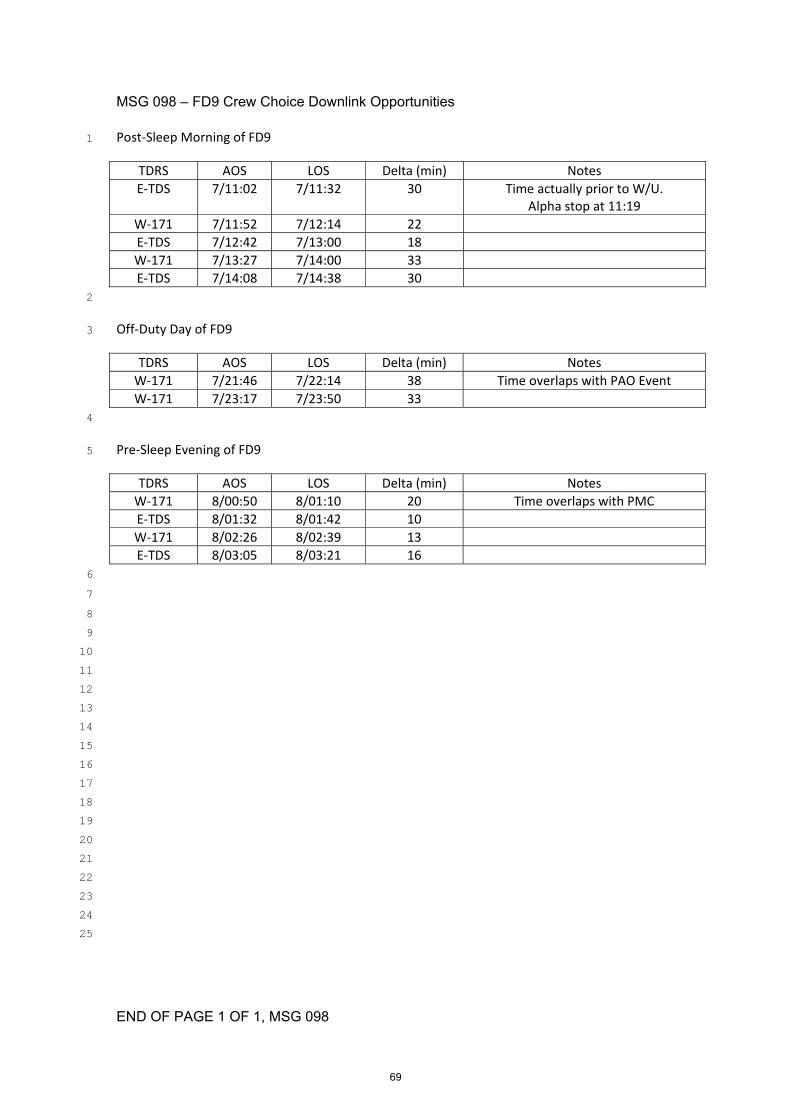
MSG 098 – FD9 Crew Choice Downlink Opportunities
END OF PAGE 1 OF 1, MSG 098
Post‐Sleep Morning of FD9 1
TDRS AOS LOS Delta (min) Notes
E‐TDS 7/11:02 7/11:32 30 Time actually prior to W/U. Alpha stop at 11:19
W‐171 7/11:52 7/12:14 22
E‐TDS 7/12:42 7/13:00 18
W‐171 7/13:27 7/14:00 33
E‐TDS 7/14:08 7/14:38 30
2
Off‐Duty Day of FD9 3
TDRS AOS LOS Delta (min) Notes
W‐171 7/21:46 7/22:14 38 Time overlaps with PAO Event
W‐171 7/23:17 7/23:50 33
4
Pre‐Sleep Evening of FD9 5
TDRS AOS LOS Delta (min) Notes
W‐171 8/00:50 8/01:10 20 Time overlaps with PMC
E‐TDS 8/01:32 8/01:42 10
W‐171 8/02:26 8/02:39 13
E‐TDS 8/03:05 8/03:21 16
6
7
8
9
10
11
12
13
14
15
16
17
18
19
20
21
22
23
24
25
69

MSG 099: STAR PAIRS PAD AND CUE CARD UPDATE
END OF PAGE 1 OF 2, MSG 099 70
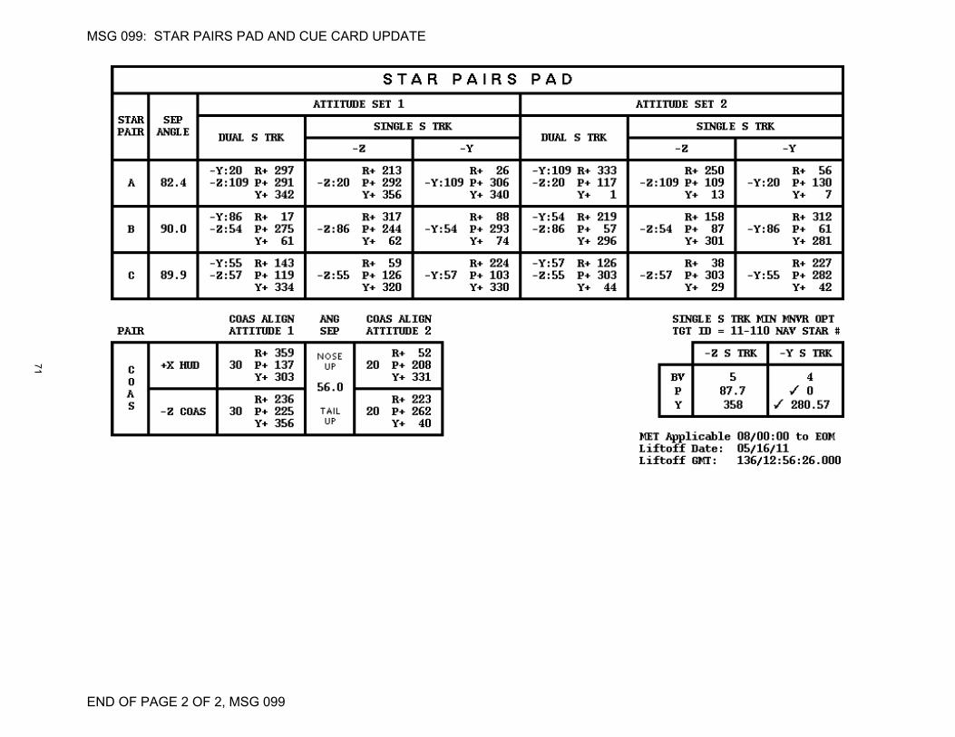
MSG 099: STAR PAIRS PAD AND CUE CARD UPDATE
END OF PAGE 2 OF 2, MSG 099
71

27-0664 (MSG 079) – ULF6 Stowage Overview for FD09 Page 1 of 1
Page 1 of 1, 27-0664 (MSG 079)
Box & Roberto, 1
2
Welcome to another day of ISS Stowage Ops! 3
4
During your Stowage Ops today we prefer for you to work on ULF6 Unpack in the 5
ULF6 Transfer Book. This way you can start getting the PMM cleaned up and we do 6
not feel you have enough time today to dig into the CWC activities. We agree with 7
your comments earlier this week and are working to come up with a location for the 8
extra CWC’s that will not fit. Once we have the updated CWC message onboard we 9
will let you know. 10
11
Due to the Russian crew sleeping during today’s activities we request you do not 12
work in ATV. Also, we believe that Sasha may still be sleeping in the Node 2 13
Overhead Crew Quarters. There will be more ATV Ops scheduled later during the 14
flight. 15
16
Thanks for all of your hard work earlier this week and keep up the great work! 17
18
ULF6 ISO Team 19
20
21
22
23
24
25
26
27
28
29
30
31
32
33
34
35
36
37
38
39
40
41
42
43 44
72