student activity manual - agedweb.orgagedweb.org/agmech/uofa survey student workbook-web.pdf ·...
TRANSCRIPT
STUDENTACTIVITY
MANUAL
LEVELINGAND
LANDMEASUREMENT
PRACTICESFOR
AGRICULTURE
AGRICULTURAL EDUCATION DEPARTMENTTHE UNIVERSfTY OF ARIZONA.
TUCSON
•
",
..

•
Activity Manual
on
LEVELING AND LAND MEASUREMENT PRACTICES
for
AGRICULTURE
Clinton o. Jacobs
Keith E. Mattox
Department of Agricultural Education
The University of Arizona~
Tucson
July. 1974Second PrintingFebruary, 1978Third Printing
July, 1986

Introduction
This Student Activity Manual is designed to provide
student involvement through a series of learning activities
and job operations concerning leveling and land measurement
practices used in agriculture.
It is intended that the student carefully follow the
written directions to each of the fourteen activities and
perform the operations as outlined or as modified by your
instructor. The companion reference presents the basic
theory and subject matter information which is essential
to the successful performance of specific operations.
The Un,ver~ily 0' Ariza".:. is iH' EEO/AA Emoteye, .InC! doc' 1'101 disctimin,ue onII'lt: 1),)51501 sex, f.:lCe. religIon. COlor, "011'01'1,)1 origIn, Vll:tn.Jm Era vcter.,u· 'ldllU.nr h,lndicaoolnq condition in its Jdmission" empluym."t "no educdllon.'pr09f,Jnn or iJctivihcs. InQuttles molY be referred to Or, Je." Ke,Hns, Anlst,,"!E.occcutlva Vice Preside"t. Administration !i03. "flo". 626·]081.
i
TABLE OF CONTENTS
READING THE LEVELING ROD
Introduction
LEVELING FIELD NOTES
LEGAL LAND DESCRIPTION
Page
i
ii
1
7
11
15
17
19
22
26
28
29
33
34
38
43
46
49
54•
55
59
61
66
67
- Laying
- Chaining
- Chaining
CHAINING . . . . . . . .Job Operation No. Va
on Level Ground. .Job Operation No. Vb
on Sloping Ground.
AERIAL MAPPING .
Subject
CHECKING THE TRIPOD LEVEL FOR PROPERADJUSTMENT . . . . . . . . . . . .
Job Operation No. VIII - Testingthe Tripod Level for ProperAdjustment . .
Table of Contents.
TRIPOD LEVEL . .Job Operation No. VII - Setting
up the Tripod Level .
LEVELING EQUIPMENT . .
LAND MEASUREMENT EQUIPMENT
DETERMINING LAND ACREAGE
DIFFERENTIAL LEVELING.Job Operation No. XI - Differential
Leveling . . . . .
PROFILE LEVELING . . . .Job Operation No. XII - Profile
Leveling . . . . . .
LAYING OUT CONTOURS ....Job Operation No. XIII
Out Contours . . .
DETERMINING GRADES, CUTS AND FILLSJob Operation No. XIV - Grading
Procedure. . .
IV
VI
II
I
x
V
IX
XI
III
VII
XII
XIV
ActivityNumber
VIII
XIII
ii

•
ACTIVITY NO. I - Legal Land Description
A. Objectives
1. To describe the rectangular system of public landsurvey.
2. To describe the location of a land area by legaldescription.
B. Introduction
The Rectangular System of land survey was implemented inthe United States as a means of identifying the locationof land boundaries. When agricultural land is sold theofficial deed contains a legal description of the landusing the Rectangular System. In this activity you willuse the information provided in the Reference Unit pp. 1-10to assist in identifying legal descriptions of land parcels.
C. Reference
1. Student Reference, Leveling & Land MeasurementPractices for Agriculture, February 1974, pp. 1-10.
D. Questions for Study
1. What country is credited with originating the scienceof surveying and land measurement?
2. What is the purpose of the Rectangular System ofland survey?
3. What is a principle meridian? A base line?
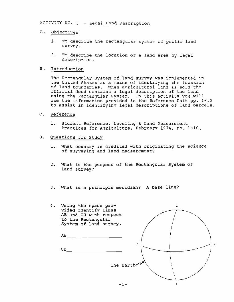
4. Using the space pro- A
vided identify linesAB and CD with respectto the RectangularSystem of land survey.
AB _
c
CD-----------.
\ /-1- B
il
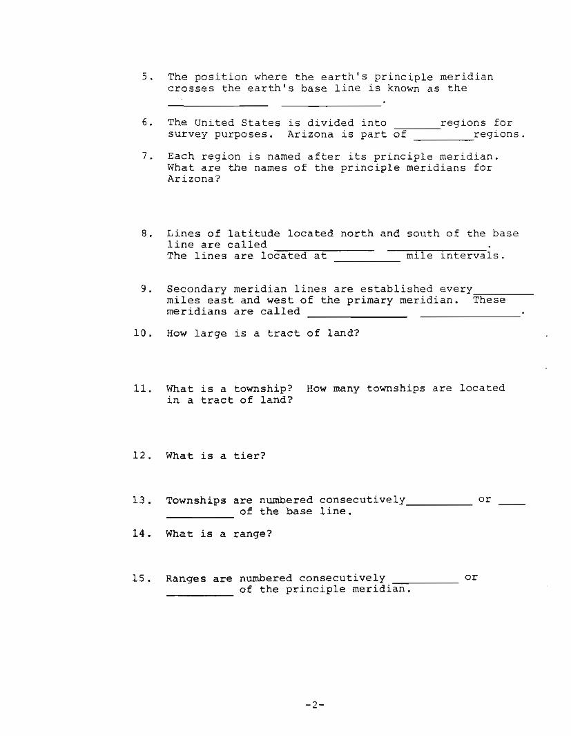
5. The position where the earth's principle meridiancrosses the earth's base line is known as the
6. The United States is divided into ~~ regions forsurvey purposes. Arizona is part of regions.
7. Each region is named after its principle meridian.What are the names of the principle meridians forArizona?
8. Lines of latitude located north and south of the baseline are calledThe lines are located at mile intervals.
9. Secondary meridian lines are established everymiles east and west of the primary meridian. ~T~h~e~s~e~--meridians are called
10. How large is a tract of land?
11. What is a township? How many townships are locatedin a tract of land?
12. What is a tier?
13. Townships are numbered consecutively orof the base line.----
14. What is a range?
15. Ranges are numbered consecutively orof the principle meridian.-----
-2-

16. Identify the ~range~ and ~tier~ of the shaded townships.
1. =2. =3. =
T4N
T3N
T2N
R6ER4ER3ER2ERIE
~f-----+----+-----I------f-'--'-..I.....J.:....L..L..:.+--------l.~
'0....~
cv:E
M~ I-----+------h-r-.rr-rr/ir----__r----t-----;....ll::
~~
IIICI)
~h'/"",.....,,....,._+----.p~-I.-l-l.....L.t----__r----i_---___1
TIN
Base Line
17. There are sections to a township.
18. There are acres in a section.
19. A section is usually mile square.
-3-

20. Number the sections in the following township:
!,,
I I,
N
21. The standard practice of writing the legal descriptionof a parcel of land is to start with thearea.
22. Draw in and label the exact area of this legal description: NW~ of Section 1, Township 34 North, Range 3East, Gila and Salt River Meridian.
Section 1
-4-

23. Write the legal description of the cross-sectionedarea in each of the following sections and providethe number of acres in each.
Section 16Township 33 NorthRange 10 WestGila and Salt River Meridian
Acres--------
Acres--------
Acres _
-5-

STUDENT INSTRUCTIONS I
Write the legal description of your own property.
Legal description _
Acreage _
-6-

ACTIVITY NO. II - Leveling Equipment
A. Objectives
1. To describe the basic principle of operation of thetripod level.
2. To differentiate between a transit level and a dumpylevel.
3. To identify operating parts of a dumpy level.
4. To list seven rules of proper care and use of thetripod level.
B. Introduction
The ability to identify and describe leveling equipmentis basic to effective communication. This knowledge alsoenables an aqriculturalist to select the appropriateinstrument and equipment for a leveling operation. Thepurpose of this activity is to develop a knowledge ofthe leveling instrument and equipment used with it.
C. Reference
1. Student Reference, Leveling & Land MeasurementPractices for Agriculture, February 1974, pp. 11-20.
D. Questions for Study
1. What is the basic purpose of the tripod level?
2. Describe the basic principle of operation of thetripod level.
3. List five types of leveling instruments and theiruses.
a.
b.
- 7 -

c.
d.
e.
4. Differentiate between a transit and a dumpy level.
5. What is the difference between a utility and turrenttype farm level?
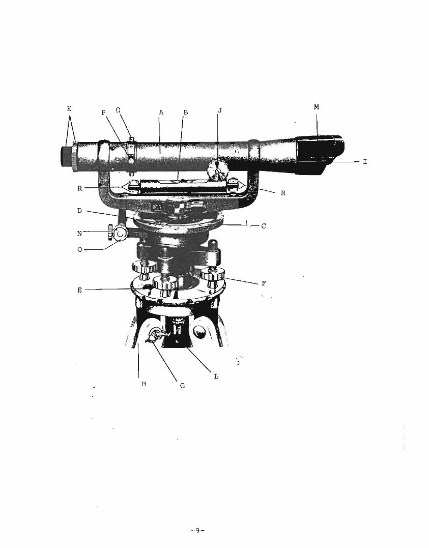
6. Using the following picture, complete the table foreach labeled part.
-8-
L
I
H G
-9-
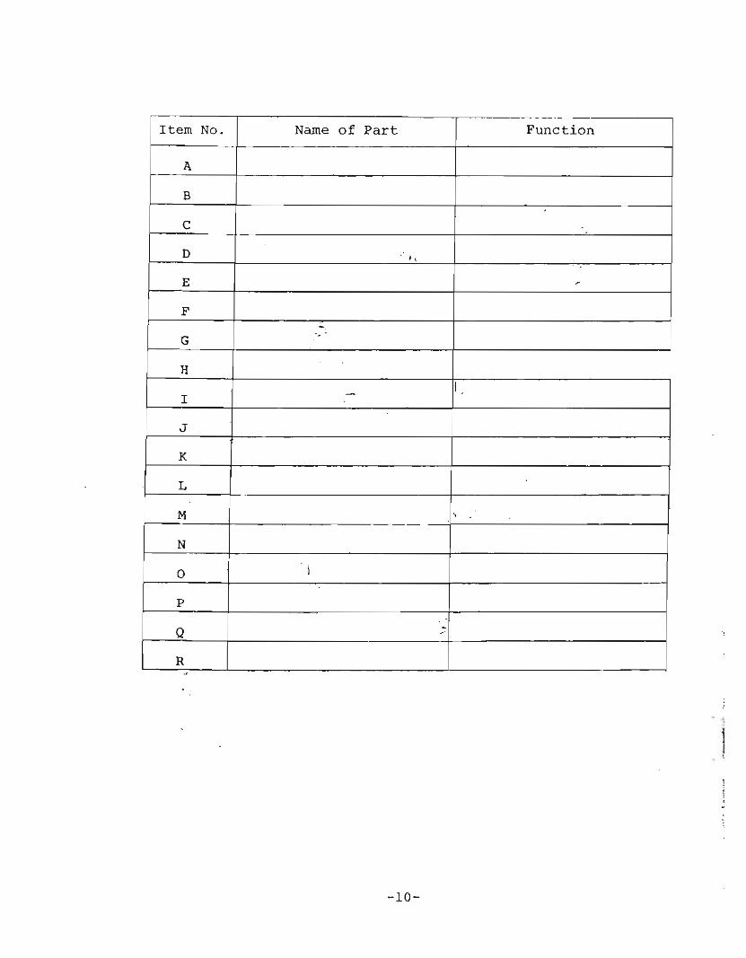
Item No. Name of Part Function
A
B.
C
D ,,
E r
F-
G -
HI
I -
J
K
L
M ,
N
0 I
p
Q --R
,
-10-

ACTIVITY NO. III - Land Measurement Equipment
A. Objectives
1. To list five methods used to measure horizontaldistances.
2. To identify equipment used in agricultural landmeasurement.
3. To differentiate between the two types of steeltapes by method of graduation.
4. To list eight principle sources of error inmeasuring horizontal distances.
B. Introduction
Several methods and a variety of mechanical equipmentare used to measure horizontal distances in agriculture.It is essential that the operator understand the methodsand the equipment used for each if the equipment is tobe properly applied. This activity is designed to develop a knowledge of land measurement methods andequipment commonly used.
C. Reference
1. Student Reference, Leveling « Land MeasurementPractices for Agriculture, February 1974, pp. 20-28.
D. Questions for Study
l. List five methods
a.
b.
c.
d.
e.
2. What is pacing?
used to measure horizontal distances.
3. Is the length of the human pace the same for allindividuals? Why?
-11-
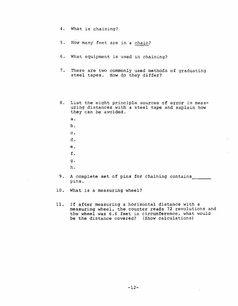
4. What is chaining?
5. How many feet are in a chain?
6. What equipment is used in chaining?
7. There are two commonly used methods of graduatingsteel tapes. How do they differ?
8. List the eight principle sources of error in measuring distances with a steel tape and explain howthey can be avoided.
a.
b.
c.
d.
e.
f.
g.
h.
9. A complete set of pins for chaining contains __pins.
10. What is a measuring wheel?
11. If after measuring a horizontal distance with ameasuring wheel, the counter reads 72 revolutions andthe wheel was 6.6 feet in circumference, what wouldbe the distance covered? (Show calculations)
-12-
12. Mr. Jones measured the length and width of hiscotton field with the above measuring wheel. Thelength of the field was determined to be 20 revolutions and the width 30 revolutions. How manyacres of cotton does Mr. Jones have? (Show calcula tions)
13. What is a geodimeter? What is the principle ofits operation?
ISTUDENT INSTRUCTIONS I
Layout a 100 foot steel tape and pace its lengthat least four times to determine the averagelength of your pace. Record the number of pacesfor each tape length below. (Show all work)
100' steel tape # paces
1st tape length
2nd tape length
3rd tape length
4th tape length
1. Calculate the average length of your pace in thefollowing space.
-13-
2. Pace off a field and determine the length of itsboundaries. Draw a map of the field and label eachboundary with the number of paces walked off and thenconvert the paces to feet and tenths of feet.
ISTUDENT INSTRUCTIONS I
Remeasure the boundaries of the field which youpaced with a measuring wheel and compare theresults by answering the following questions.
1. What is the circumference of the measuring wheelyou used?
2. Draw a map of the field measured and label eachboundary with the wheel revolutions and converteach to feet and tenths of feet.
-14-
ACTIVITY NO. IV - Determining Land Acreage
A. Objectives
1. To calculate acreage of various shaped agriculturalland parcels.
B. Introduction
Land measurement practices in agriculture are used todetermine field boundaries and the exact acreage of landwithin the boundaries. Acreages for certain crops arelimited by federal controls. Any acreage in excess of thatset by the federal government is at a loss to the agriculturalist. It is therefore important that he calculate thequantity of land within a field to conform to legal limits.Knowing the amount of land acreage is necessary when purchasing fertilizer, pesticides, seed, etc.
This activity provides the student with the opportunityto calculate acreage of various shaped parcels of land.
C. Reference
1. Student Reference, Leveling & Land MeasurementPractices for Agriculture, February 1974, pp. 29-32.
D. Questions for Study
1. How many acres are there in a rectangular field 1326feet long and 561 feet wide?
2. A farmer wishes to build a fence around a squarefield measuring a total distance of 640 rods. Howmany posts will he use, when he places them 16~ feetapart?
3. How much 3-wire fencing is needed to enclose a fieldthat measures 190 feet, 212 feet, 190 feet and 212feet on each of the four sides, respectively?
4. How many acres are there in a triangular field, ifthe base is 5000 feet and its altitude is 750 feet?
5. What is the cost of a pasture of rectangular shapepurchased for $50.00 per acre, measuring 3 miles longand 2 miles wide?
-15-
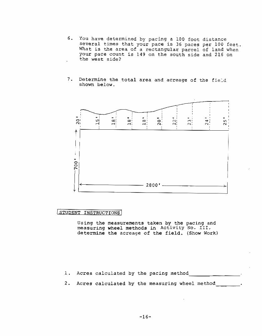
6. You have determined by pacing a 100 foot distanceseveral times that your pace is 36 paces per 100 feet.What is the area of a rectangular parcel of land whenyour pace count is 149 on the south side and 216 onthe west side?
7. Determine the total area and acreage of the fieldshown below.
-I
0'Nt
, ,, ,
, , , I I-. , , I- , , . I -lri
,",,' I
00: 00 I co' O. N' ("1' It'\
~ ..-4: ....l: N: N:I I..-4: N, N, N
II
I
foof"
ll~(-
ISTUDENT INSTRUCTIONS I
2800 I -----------~>_I
Using the measurements taken by the pacing andmeasuring wheel methods in Activity No. III,determine the acreage of the field. (Show Work)
1. Acres calculated by the pacing method----------2. Acres calculated by the measuring wheel method _
-16-
ACTIVITY NO. V - Chaini~g
A. Objectives
L To measure horizontal distances using the steel tapeand chaining pins.
2. To list eight errors in measuring with the steel tape.
B. Introduction
The steel tape is considered by many agriculturaliststhe most practical method of land measurement. Itssuccess and accuracy is dependent upon a knowledge of theequipment and procedures used. In this activity you willbe involved in measuring horizontal distances with thesteel tape.
C. Reference
1. Student Reference, Leveling & Land MeasurementPractices for Agriculture, February 1974, pp. 46-51.
D. Questions for Study
1. A survey crew has completed measurement of a fieldfor determining acreage. The tape used has an extrafoot before zero numbered in a backward direction.(Figure 2-14b Reference Unit II) Answer thefollowing questions concerning the measurements:
a. After measuring line A the rear chainman held9 pins and the 56 foot mark aligned with thelast chaining pin. What is the distance measured?
b. After measuring line B the rear chainman held 5pins in his hand and the 75 foot mark alignedwith the last chaining pin. The head chainmanheld the .7 on the chain. What is the distancemeasured?
c. Round off the length of the sides A and B to thenearest foot, then determine the acreage of thefield. The field is rectangular in shape.
d. The rear chainman holds 4 pins in his hand, hasone in the ground and is holding 68 feet on thechain, then the head chainman has gone, _feet from the starting point.
-17-

2. List eight errors in measuring with the steel tape.
a",.:
b.
c.
d.
e.
f.
g.
h.
3. When chaininq on sloping ground, pins are used at each__________o.f the chain.
4. What is a breaking point?
5. Why is the plumb bob used when taping on sloping ground?
6. When chaining on sloping ground, a correction factor isto the surface distance to obtain a true
hor~zontal distance.
7. What is the m thematical formula for the correctionfactor?
8. If the slope of a measured distance was 8 percent,and the measured distance was 600 feet, what wouldbe the correct lineal distance measured?
-18-

JOB OPERATIO NO. Va - Chaining on Level Ground
STUDENT INSTRUCTIONS
Using the chaining method for level ground, measurea predetermined distance using the following steps ofprocedure.
Equipment:
-100' Steel tape-Range poles-11 chaining pins
with holder
Materials:
-Pencil-Field notebook
The steel tape (chain) you are using is ~feet longand the first foot is divided into ~ .parts perfoot numbered in a direction.
Steps of ProcedureIllustrations/Key Points/
Safet Practices
A. Settin Poles
1. The head chainman setsthe range poles at thebeginning and end ofthe line to be measured.
a. The range poles are usedfor "lining-in" purposes.
B.
2. While the head chainmanis setting the rangepoles the rear chainman"throws" the tape bylaying it out in thegeneral direction ofthe line to bemeasured.
a. Be careful to avoid loopingor twisting the tape.
c. Chainin 0 eration
3. The head chainmantakes the zero (O)endof the tape, and movesforward pulling thetape toward the endrange pole.
- 19 -

Steps of Procedure
4. As the 100 foot markof the tape nears thefirst pin, the rearchainman calls out"chain". The head chainman halts and placeshimself in a straightline with the range polesaided by signals fromthe rear chainman.
Illustrations Key PointsSafet Practices
D. Setting Pins
5. After aligning the tape,the rear chainman holdsthe 100 foot mark exactly even with the pin.When the 100 foot markis properly aligned therear chainman calls out"right hetl<l!~'~ 'Ztii" ~ 01$signal for ~.~~chainman to ~ ~
a. The head chainman kneelsand applies approximately10-12 pounds of tension tothe tape with his left armbearing against his leg.
6. The head d:wi.~ (lij.~
a pin on l~ ~~ lto the zer~ .~ q$ ~~tape . Onc~ ..~ ,~ .:J1.m 'set the he~~ lalso calls ~ .~ Ihere" . Th;ir;l 111 ~. $~.- i .nal' for th~ ~ ~12aS'CIto pull hi~ pia. i
7. The rear caaJ,qm 1IlQ1:tahis pin.
8. After the head chainmansets his eleventh orlast pin he calls out"tally" .
9. The rear chainman bringsforward ten pins and givethem to the head chainman.
-20-

Steps of Procedure Illustrat~ons Key Po~nts
Safet Practices
E. Kee ing Field Notes
10. Record tallies on a fieldnotebook page found on page24.
a. The number of tallies recorded will be the numb0.rof thousands of feet whichhave been measured.
11.
F. Continuing
Continue the chainingprocedure as describedabove.
Operation
G. Completing Chaining Operation
12.
13.
When the end of the landdistance to be measured isreached, the head chainman halts and the rearchainman moves to the lastpin where he adjusts thetape so that an even footmark is aligned with thepin. This is done so thatthe head chainman's end ofthe tape will fall withinthe section of the tape whichis subdivided.
The head chainman reads thenumber of tenths and estimates hundredths. The rearchainman identifies thenumber of the foot mark whichis opposite the pin.
a. Proper tension is appliedto the tape.
a. The tenths and hundredthsare added or subtractedfrom the foot mark dependingon the type of tape graduation used. (See pages 48-49,Reference Unit III)
H. Determining Error
14. Remeasure the distanceabove by measuring back tothe starting point. Determine the difference in thetwo readings.
15. If there is a difference inthe two measurements whatcould have caused thedifference?
-21-

JOB OPERATION NO.Vb - Chaining on Sloping Ground
STUDENT INSTRUCTIONS I
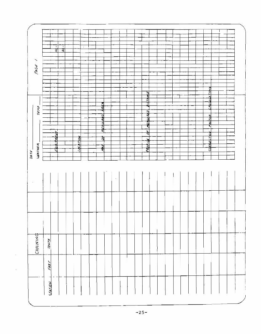
Measure a predetermined distance on sloping groundusing the steps of procedure described below. Record your measurements on a field notebook page asillustrated in Reference Unit III, Page 51.
Equipment:
-100' Steel tape-11 chaining pins with
holder-Plumb bob-Hammer
Steps of Procedure
Materials:
-Pencil-Field notebook-Wooden stakes
I ustrat~ons Key Po~nts
Safety Practices
A. Throwing Ta e
1. The head chainman "throws"the tape by laying it outin the general directionof the line to be measured.
a. Avoid looping or twistingthe tape.
B. Chainin Operation
2. When moving up hill, thehead chainman takes thezero (0) end of the tapeand moves forward to apoint selected by the rearchainman.
3. The rear chainman holds hisend of the tape at chestheight. With the aid of aplumb bob, the rear chainmanwill hold an even foot markdirectly over the startingpoint. This is done so thatthe head chainman's end of thtape will fall within thesection of the tape which issubdivided into tenths.
a. The rear chainman selectsthis point by estimationor with the use of a handlevel while holding hisend of the tape at chestheight. The head chainmanwill hold the chain at thispoint on the ground. Thispoint will be marked witha chaining pin.
-22-

Steps of Procedure I
4. The head chainman "callsout" the tape reading intenths and hundredths. Therear chainman "calls out lt
his tape reading in evenfeet.
5. This process continuesuntil the end of the distancemeasured is reached.
a. Both chainman make theaddition or subtractiondepending on the type oftape used and check eachother's results. The resultsare entered in the fieldnotes found on page 25.
a. The total number of feetmeasured is obtained bysumming the distancemeasured at each station.
C. Correction Factor
6. Add correction factor to a.the surface distance obtainedin Step 5.
52-=2TO~O-- per 100 ft.
5 = percent slope
-23-
Distancemeasured
+ Correctionfactor
Correctlineal= distancemeasured

-
I
L----_==-24_-
-
.III,
I
I;
I
i I
I!
i
--1
I,,
-
I
;
;
-I
,
II .- f--
I.....i
,,I
i
I
I -- .- - _.iI
I
I I ,.
I -I.....
,L-
I .:L-
~'"
I
i
~"
~~
~ J "0:
,
,
I
I
I,
I
I
~-2:-S----)
-rnttttt+tH+H-W+ULL- -1-- -r-+-J- TTt11tt++t-++-H-Wllllf--- -

ACTIVITY NO. VI - Aerial Mapping
A. Objectives
1. To measure land distances by the use of aerial maps.
2. To calculate land acreage by use of aerial maps.
B. Introduction
With the aid of aerial maps agriculturalists can determineland distance and acreage quickly and accurately. Aerialmaps may also reveal low areas that may require minor landleveling. Upon completion of this activity you will beable to determine land distances and acreage using aerialmaps of agricultural areas.
C. Reference
1. Student Reference, Leveling & Land MeasurementPractices for Agriculture, February 1974, pp. 54-56.
D. Questions for Study
1. With the use of aerial maps agricUlturalists canmeasure land and determine _
2. What is a map measurer?
3. When using a sheet of paper to measure map distancehow would you measure a curved line?
ISTUDENT INSTRUCTIONS IUsing the aerial map on the following page measurefield boundaries of the fields dp.siqnated by yourinstructor and determine their acreage.
F~eld
No. Boundarv Distances Acres
-26-

ACTIVITY NO. VII - Tripod Level
A. Objectives
1. To set up the tripod level for a level line of sight.
2. To measure horizontal distances with a level.
B. Introduction
The success and accuracy of the sightings and measurements taken with the tripod level hinge greatly uponthe procedure followed in setting up the instrument. Inthis activity you will use accepted techniques toproperly set up and adjust the tripod level.
C. Reference
1. Student Reference, Leveling & Land MeasurementPractices for Agriculture, February 1974, pp.33-36.
D. Questions for Study
1. How should the leveling instrument be removed fromits case?
2. How should the leveling screws be grasped?
3 • The leveling screws should be rotated by bringingthe thumbs of the hand or _from one another.
4. Turning both leveling screws "in" moves the bubbleto the
5. When the bubble in the leveling tube moves to theleft, both leveling screws are being turned _
• (outward or inward)----
-28-
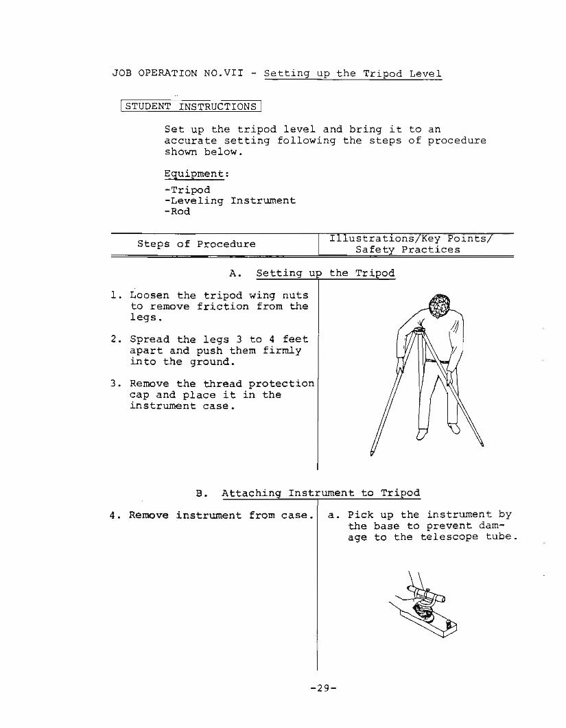
JOB OPERATION NO.VII - Setting up the Tripod Level
jSTUDENT INSTRUCTIONS I
Set up the tripod level and bring it to anaccurate setting following the steps of procedureshown below.
Equipment:
-Tripod-Leveling Instrument-Rod
Steps of Procedure ustrat10ns Key P01ntsSafet Practices
A. Settin u the Tripod
1. Loosen the tripod wing nutsto remove friction from thelegs.
2. Spread the legs 3 to 4 feetapart and push them firmlyinto the ground.
3. Remove the thread protectioncap and place it in theinstrument case.
B. Attachin Instrument to Tri od
4. Remove instrument from case. a. Pick up the instrument bythe base to prevent damage to the telescope tube.
-29-

Steps of Procedure
5. Attach the instrument tothe tripod by holding theinstrument in one hand andturning the base with theother.
6. Remove the lens protectioncap and place it in theinstrument case.
7. Attach the sunshade.
ustrat~ons Key Po~nts
Safet Practices
a. CAUTION: Tighten thebase snugly with thehand - DO NOT FORCE.
-30-

Steps of Procedure
C. Leveling Instrument to Rou h Setting
8. Set the telescope tube overtwo legs and push one leginto the ground until thebubble in the level tube isapproximately centered.
9. Rotate the telescope tubeover the third leg andapproximately center thebubble.
11. If the rod is within thelimits of the level, tightenthe wing nuts, if not, moveto a new location.
10. Sight through the instrumentto determine whether the rodwill come within the limitsof the level.
Rod not within limits of level
----------- ..
Rod within limits of level
D. Levelin Instrument to Accurate Settin
12. Rotate the telescope tubein alignment with twoleveling screws. Graspthe two screws between thethumb and forefinger ofeach hand. Rotate thescrews by bringing thethumbs of the hand towardor away from one another.
13. Keep the leveling screwsworking firmly against oneanother but avoid binding.
-31-
a. The bubble in the levelingtube will follow the movement direction of the leftthumb.
Steps of Procedure
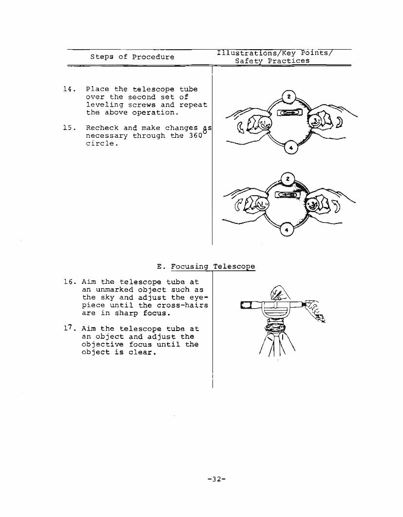
14. Place the telescope tubeover the second set ofleveling screws and repeatthe above operation.
15. Recheck and make changes 8snecessary through the 360circle.
I lustrat~ons Key Po~nts
Safet Practices
E. Focusing Telesco e
16. Aim the telescope tube atan unmarked object such asthe sky and adjust the eyepiece until the cross-hairsare in sharp focus.
17 • Aim the telescope tube atan object and adjust theobjective focus until theobject is clear.
-32-

ACTIVITY NO.VTII-Checking the Tripod Level for ProperAdjustment
A. Objectives
1. To set up and test the tripod level for properadjustment.
2. To set up and test the adjustment of the horizontalcross hair.
B. Introduction
Occasionally the leveling instrument is bumped or joltedout of adjustment. When this happens the line of sightand bubble of the level are not coordinated; therefore,the sightings taken will be incorrect. This activityis designed to teach you how to check the levelinginstrument for proper adjustment.
C. Reference
1. Student Reference, Leveling & Land MeasurementPractices for Agriculture, February 1974, pp. 37-39.
D. Questions for Study
1. What effect would the following have on a levelinginstrument?
a. Thumb screws on the tripod are loose.
b. Leveling screws are not firmly seated on thebase plate.
c. Leveling tube is not parallel with objective andeyepiece crosshairs.
2. Who should perform repairs on a leveling instrument?
-33-
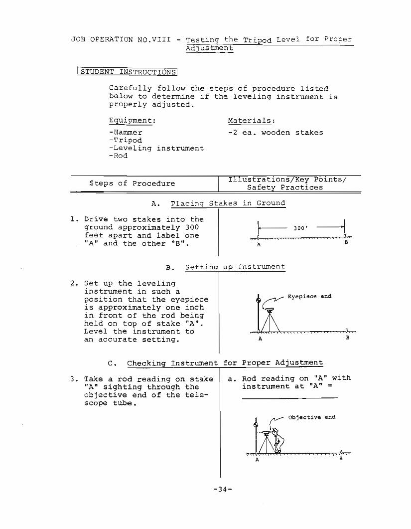
JOB OPERATION NO.VIII - Testing the Tripod Level for ProperAdjustment
[STUDENT INSTRUCTIONS I
Carefully follow the steps of procedure listedbelow to determine if the leveling instrument isproperly adjusted.
Equipment:
-Hammer-Tripod-Leveling instrument-Rod
Materials:
-2 ea. wooden stakes
Steps of Procedure ustrat~ons Key Po~ntsl
Safet Practices
A. Placinq Stakes in Ground
1. Drive two stakes into theground approximately 300feet apart and label one"A" and the other "B".
B. Settinq up Instrument
2. Set up the levelinginstrument in such aposition that the eyepieceis approximately one inchin front of the rod beingheld on top of stake "A".Level the instrument toan accurate setting. A
~ Eyepiece end
B
C. Checkin Instrument for
3. Take a rod reading on stake"A" sighting through theobjective end of the telescope tube.
a. Rod reading on "A" withinstrument at "A" =
-34-
Steps of Procedure
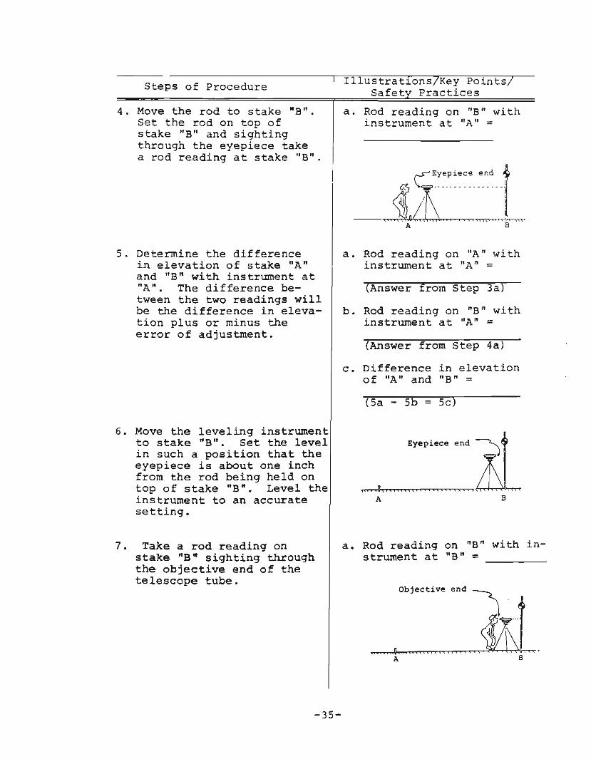
4. Move the rod to stake -B".Set the rod on top ofstake "B" and sightingthrough the eyepiece takea rod reading at stake "B".
5. Determine the differencein elevation of stake "Anand "B n with instrument at"A". The difference between the two readings willbe the difference in elevation plus or minus theerror of adjustment.
Illustrations/Key Points/Safet Practices
a. Rod reading on "B" withinstrument at "A" =
~Eyep.ece end f11 \J:-'.'--" -. _.....1!J~iu "". ~
A B
a. Rod reading on "A" withinstrument at "A" =
(Answer from Step 3a)
b. Rod reading on "B" withinstrument at "A" =(Answer from Step 4a)
c. Difference in elevationof "A" and "B" =
(Sa - 5b = Sc)
6. Move the leveling instrumentto stake "B". Set the levelin such a position that theeyepiece is about one inchfrom the rod being held ontop of stake "B". Level theinstrument to an accuratesetting.
A
Eyepiece end~
B
7. Take a rod reading onstake "B ft sighting throughthe objective end of thetelescope tube.
a. Rod reading on "B" with instrument at "B" =
Objective end~
-35-
A
Steps of Procedure
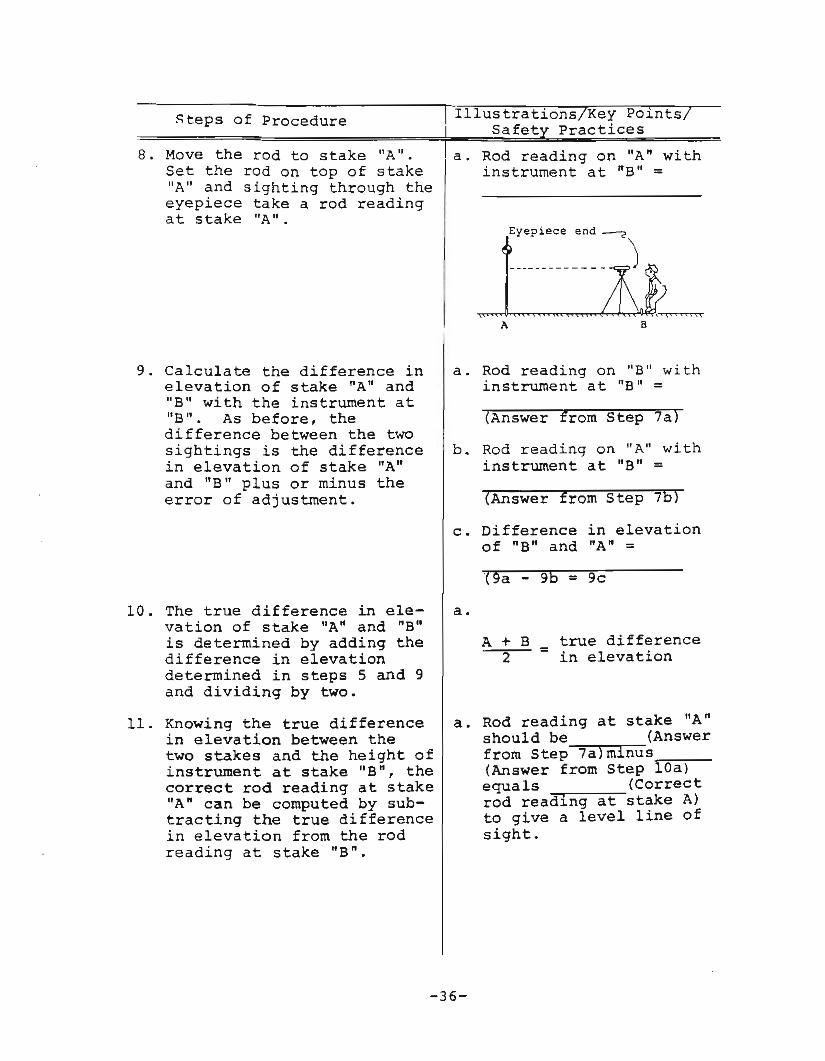
8. Move the tod to stake "A".Set the rod on top of stake"A" and sighting through theeyepiece take a rod readingat stake "A".
A B
9. Calculate the difference inelevation of stake "An and"B" with the instrument at"B". As before, thedifference between the twosightings is the differencein elevation of stake "Anand "B" plus or minus theerror of adjustment.
a. Rod reading on "B" withinstrument at "B" =
(Answer from Step 7a)
b. Rod reading on "A" withinstrument at nB" =(Answer from Step 7b)
c. Difference in elevationof nB" and "A" =
(9a - 9b - 9c
10. The true difference in elevation of stake "A" and "B"is determined by adding thedifference in elevationdetermined in steps 5 and 9and dividing by two.
a.
A + B2
true difference= in elevation
11. Knowing the true differencein elevation between thetwo stakes and the height ofinstrument at stake "B", thecorrect rod reading at stake"A" can be computed by subtracting the true differencein elevation from the rodreading at stake "B n.
a. Rod reading at stake "A"should be (Answerfrom Step 7a)mlnus~~__(Answer from Step lOa)equals (Correctrod reading at stake A)to give a level line ofsight.
-36-
Steps of Procedure
D. Calculatin
12. Determine the amount ofadjustment needed.
Illustrat~ons Key PointsSafet Practices
Ad "ustment
a. Rod reading at stake "A"from instrument at "B"equals (7b) minus
(llal reading~t~o~g~ir.v~e~a~ level line ofsight. This requires
(No. feet ad""j-:u"'s"'t--m:-e:-n:-t:-<"")-t0 be rnade inthe instrument's levelingtube.
E. Checkin the Horizontal Cross Hair
13. With the leveling instrumentstill set up and leveled atstake B and sighted at thetarget on the rod held onstake A, rotate the level backand forth slightly from sideto side. If the ends of thecross hair cut the target inthe same place as did thecenter of the cross hair,it is in adjustment. If theends of the cross hair do notremain on the spot as did thecenter, the cross hair shouldbe adjusted.
-37-

ACTIVITY NO. IX - Reading the Leveling Rod
A. Objective
accurately.
l. To explain the purpose of the leveling
2. To identify the parts of a rod.
3 . To read a leveling rod.
4. To extend and secure the leveling rod
5. To use and interpret field signals.
6. To perform as a rodman.
rod and target.
B. Introduction
A leveling rod is the "measuring stick" of surveying andleveling operations. Its accurate use depends greatlyupon the surveying crews' ability to hold, extend, andread a leveling rod correctly. The ability to accuratelyread a leveling rod is necessary for most agriculturalleveling operations. You will also use and interpretfield signals.
C. Reference
1. Student Reference, Leveling & Land MeasurementPractices for Agriculture, February 1974, pp. 39-45.
D. Questions for Study
1. What is a leveling rod?
2. Most leveling rods consist of.~ or~ ~_
sections of hardwood to, feet in length.
3. Major divisions of the rod in feet are shown in large(color) numbers.
Between4 • each foot________ (color) ._________of a foot
indicator are numbers inEach of these -n-umb~-e-r-s--representmeasurement.
-38-

3. To prepare a page of field notes.
B. Introduction
One of the most important operations accomplished by thesurveying crew is keeping accurate and complete fieldnotes. It is obvious that no matter how carefully theleveling operation is done or how accurate the measurements, all is rendered valueless if the field notes areincomplete or unclear. This activity will teach you theproper and accepted procedure for taking field notes.
C. Reference
1. Student Reference, Leveling & Land MeasurementPractices for Agriculture, February 1974, pp. 44-47.
D. Questions for Study
1. What is a bench mark (BM)?
2. What points can be used as bench marks?
3. If the elevation of a bench mark is unknown, whatshould be done?
4. A rod reading taken on a point of known elevation iscalled a _
5. How is the height of instrument (HI) determined?
6. What is a foresight (FS)?
-43-

7. When is a turning point taken?
8. What are field notes?
9. Why are they kept?
10. What are four types of field notes?
a.
b.
c.
d.
11. Complete a set of notes on the following fieldnotebook ~age using the information obtained inActivity No. III on pacing.
- 44 -

L II --, I
, -,
'\
-.
.+--=l1
,~
I I
~!
I
, ,
,
!
I
, 1
I i
,,
I -,- ;
I --r::-_-I I l
,.,
"T
, ,
, I ,
!
-<
iI
"TI "1
TI
i '!
Il I
I I II
,
I
i I
: i II I ,! I I
i ! !
! ! I"
I I
! ! I [I I~1-! :1
" ! : tt--rrtttH-r-H-H++-++-WJJl-I'I I I i II: 'II
!
I I
ACTIVITY NO. XI - Differential Leveling
A. Objectives
1. To determine the difference in elevation of two points.
2. To develop skill in keeping accurate field notes ondifferential leveling.
B. Introduction
The basic function of the tripod level is determiningdifferences in elevation between two points. A widevariety of agricultural jobs require that elevation orchange in elevation be known. It is the purpose of thisactivity to describe the process and procedure of determining changes in elevation between points by differentialleveling.
C. References
1. Student Reference, Leveling & Land MeasurementPractices for Agriculture, February 1974, pp. 57-60.
D. Questions for Study
1. What is the most accurate way we have at our disposalto find the difference in elevation between two pointswhich are not within sight of one another?
2. How many people'are on a differential survey crew?What are they called?
3. How do we keep a running account or record of ourprogress in a differential survey?
-46-
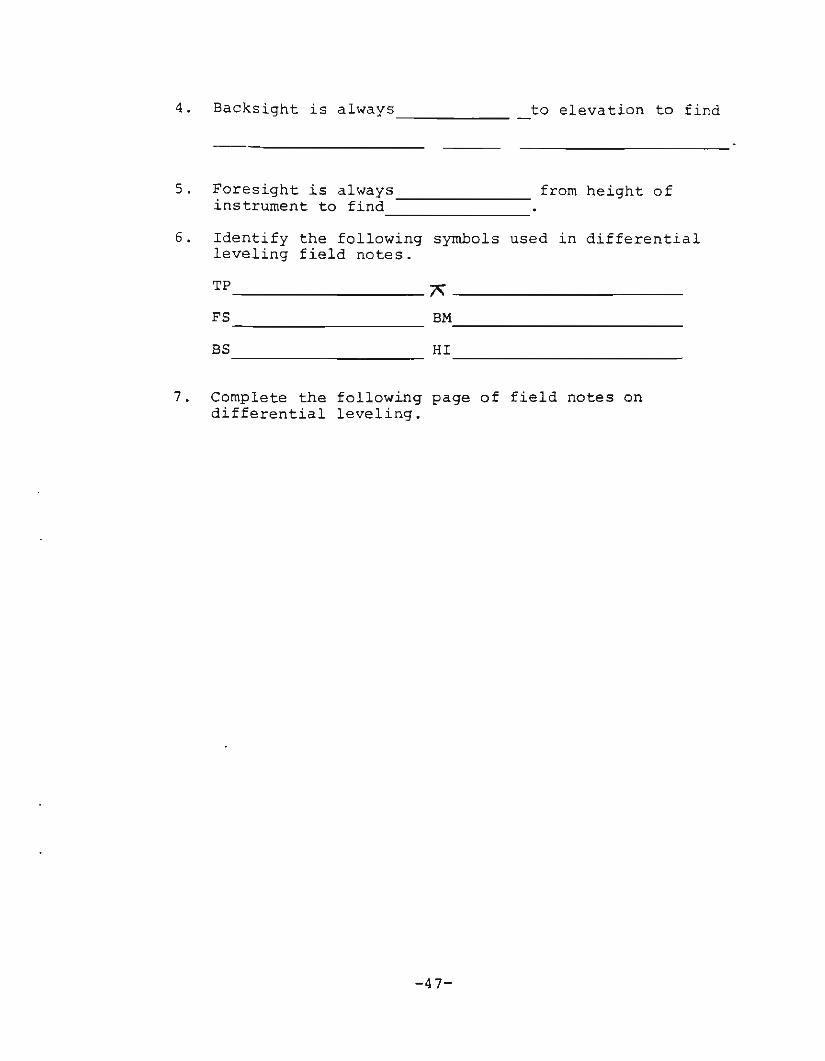
to elevation to find4. Backsight is always _
5. Foresight is always __instrument to find __
from height of
6. Identify the following symbols used in differentialleveling field notes.
TP A _
FS _ BM _
BS HI _
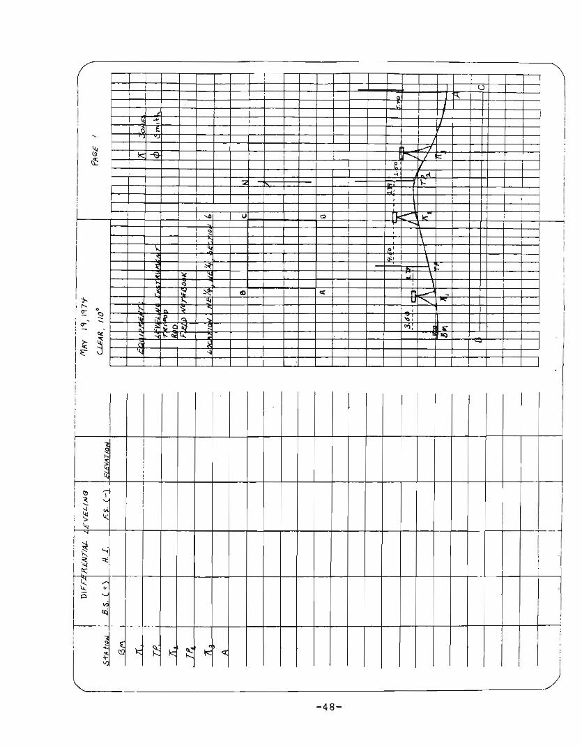
7. Complete the following page of field notes ondifferential leveling.
-47-
u
..I-
•
.,
I
-
(I!
I~~
'"
I I
~)
,'0,">,
".'
-48-
til
I
II:}-, ....
<r •,- <:)
: 0"'''' ::::
i ~ ~.i~ J
!
I
Ir--I,,,
I I I
I
.
,
1
,
J
,I
I i~
I I I I
l II
I
I I
I,
I!
I '" ~ II "'-, ::J ,,;,~
,
L" ",
I
! ~ I
1
i~ '-i
L~ '"
I
~ ;'l,: "
1--1"- ~
'" ~~«i
I
! I
--4 . - ..
~ ~ ~--~ ~ ~ ~I!
I I ~
!
I
I
-
;
I
I
I I I I;

JOB OPERATION NO. XI - Differential Leveling
ISTUDENT INSTRUCTIONS I
Carefully follow the steps of procedure listedbelow to determine the difference in elevationbetween two points. Record your findings ona field notebook page.
Equipment:
-Tripod-Leveling instrument-Rod
Materials:-Penc~l
-Field notebook
Steps of Procedure I ustrat~ons Key PointsSafet Practices
A. Establishin a Bench Mark
1. Establish a Bench Mark. a. Concrete well curb,corner of a road culvert,or any other permanentfeature. If elevation isunknown, arbitrarilyassign 100 ft.
8M A
B. Setting up Leveling Instrument
2. Set up and level the instrument to an accurate settingsome distance away from theBM in the direction of survey. (Toward point A)
a. The distance from theinstrument to the BMshould not be so great asto make it impossible toread the rod accurately.Not more than 150 to 200feet.
-49-

Steps of Procedure ustrat10ns Key PointsSafety Practices
c. Taking a gacksi~ht
a. After taking the readingcheck the bubble in thelevel tube to insure theinstrument is level.
3. Take a Backsight readingon the rod held on theBench Mark by the rodman.Record the reading in theBS column of BM in thefield notes. Use the fieldnotebook page on page 53 torecord your sightings. r
ACkSight (95) onknown eleva':.icn--.......&1>
BM AI A
4. Determine the Height ofInstrument. Record theHeight of Instrument inHI column of~, in the fieldnotes.
a. To obtain Height of Instrument, the BS is added tothe Bench Mark elevation.
BS + BM = HI
D. Moving Rod to New Location (TF)
5. Give the "all right" signalto the rodman. At thissignal the rodman willmove to a new point alongthe route of survey.
6. The rodman moves towardpoint A, limited by distanceand changes in elevation.
a. DO NOT MOVE OR ADJUST THEINSTRUMENT AT THIS TIME.
~I.~'-'
a. The rodman sets the rodon solid ground with thefront face of the rodplainly visible to theinstrument man.
~BM&-L7\,
-50-
Steps of Procedure Illustrat~ons Key PointsSafety Practices
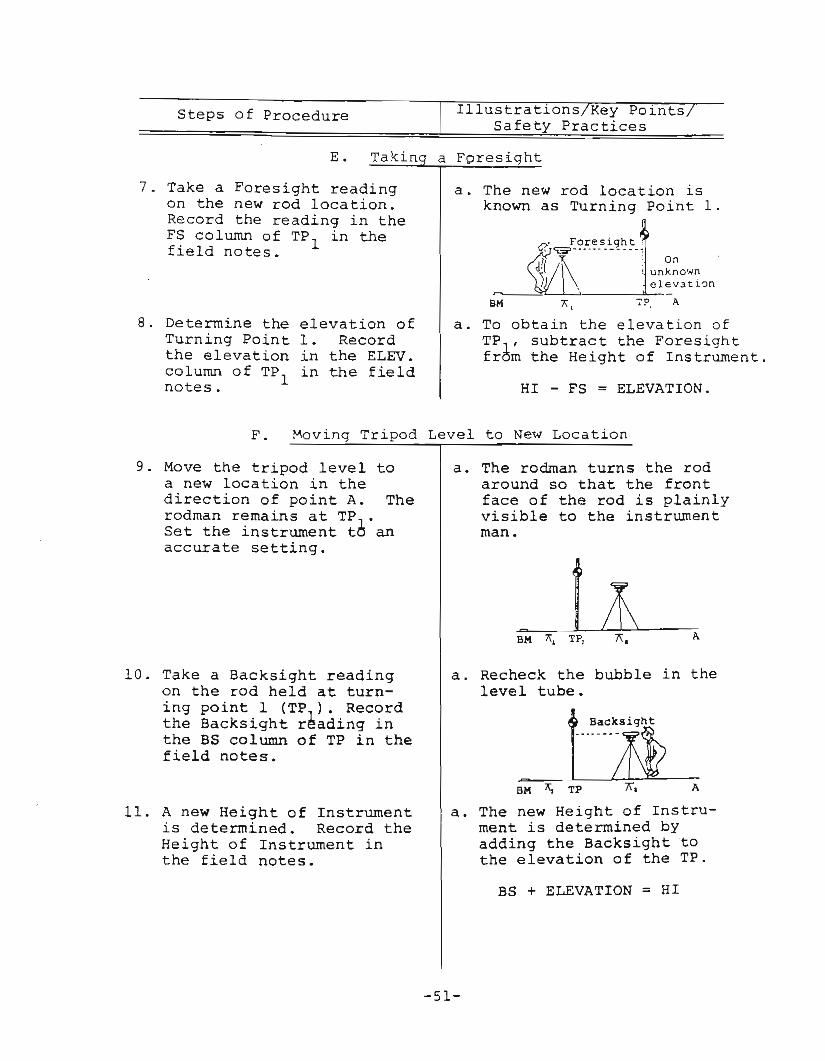
E. Takin a Foresiqht
7. Take a Foresight readingon the new rod location.Record the reading in theFS column of TP
lin the
field notes.
a. The new rod location isknown as Turning Point 1.
. Foresight,
~1-~....---m1 une~o'.n, \\ elev3tlon
BM 7? A
8. Determine the elevation ofTurning Point 1. Recordthe elevation in the ELEV.column of TP
lin the field
notes.
a. To obtain the elevation ofTP , subtract the Foresightfr~m the Height of Instrument.
HI - FS = ELEVATION.
F. ~ovinq Tripod Level to New Location
9. Move the tripod level toa new location in thedirection of point A. Therodman remains at TP,.Set the instrument to anaccurate setting.
10. Take a Backsight readingon the rod held at turning point 1 (TP,). Recordthe Backsight reading inthe BS column of TP in thefield notes.
11. A new Height of Instrumentis determined. Record theHeight of Instrument inthe field notes.
a. The rodman turns the rodaround so that the frontface of the rod is plainlyvisible to the instrumentman.
Lt~BM~7i=-,-TP, 7';. ~---:A
a. Recheck the bubble in thelevel tube.
tBacksight
.....--~
~-=--BM Xl TP 7\. A
a. The new Height of Instrument is determined byadding the Backsighttothe elevation of the TP.
BS + ELEVATION = HI
-51-

Steps of Procedure11 ustrat10ns Key P01nts
Safety Practices
G. Counting Differential Leveling Procedure
12. Repeat Steps 1 through 11until Point A is reachedand its elevation relativeto the Bench Mark is obtained.
a. Record all sightings inthe field notes.
-52-
I
--
,
I IIII I I I
iiI
II
I I
i__l'i_U"~+It'-~H~i1+trrHljjl1r~r~,I _I
r---- -
! I ~I~~,=-'_'------LI_: --------- - -53-
i=~JtlTL~H~-t++tH-ttttttU1IJT~:I ! r--Ul~~+H+H-HH-t1Tn_--J-t- T I
ACTIVITY NO. XII - Profile Leveling
A. Objectives
1. To determine the difference in elevation of aseries of points along a given line.
2. To develop skill in keeping accurate field noteson profile leveling.
B. Introduction
A variety of agricultural applications require theelevations of a series of points along a given linebe known. Profile leveling is essential to layoutsewer lines, drains, ditches, or similar structures.This activity provides the student with the opportunityto perform profile leveling.
C. Reference
1. Student Reference, Leveling & Land MeasurementPractices for Agriculture, February 1974, pp. 61-64.
D. Questions for Study
1. What is the principle difference between differential leveling and profile leveling.
2. What is a station?
3. How are stations identified or recorded?
4. Write the elevations of the following stationsused in profile leveling.
6 + 01
3 + 00
2 + 25
5. Write the normal station marking for the followingelevations.
150 feet
100 feet
226 feet
- 54 -

JOB OPERATION NO.XII - Profile Leveling
I STUDENT INSTRUCTIONS I
Carefully follow the steps of procedure listedbelow to perform profile leveling. Record yourfindings on a field notebook page.
Equipment:
-Tripod-Leveling instrument-Rod-Hammer
Materials:
-Wooden stakes-Field notebook-Pencil
Steps of Procedure I ustrat~ons Key Po~nts
Safet Practices
~
+oo
be set at
Change
o+'"o
o+oo
in~evation
~---'------'" \ )-'--_.........~/....+ .... +0+'"o ~ 0
'"
A. Marki~ thp- Stat~
1. The line to be profile lev- a. Stakes shouldeled must be marked off each station.("stationed") at intervalsof 50 ft. or at each sharpchange in land surface.
B. Settin
2. Set up the tripod level andbring it to an accuratesetting. Set the levelapproximately 150 to 200 feetfrom station 0+00 in thedirection of survey.
'-------'--------":J~~o 0 +...... ++ + 0 + l.11 0o l.11 0 """ 0 0o 0 '"
C. T~king a Backsi ht
3. Take a Backsight on aBench Mark to establishthe Height of Instrument.Set up a field notebookpage for profile levelingsimilar to the one shownon page 63 in the ReferenceUnit. Record the BS readingin the BS column of BM. Usethe field notebook page onpage 58 to record yoursightings.
BM 0+oo
o+'"o
-55-
Steps of ProcedureIllustrations/Key Points/
Safety Practices
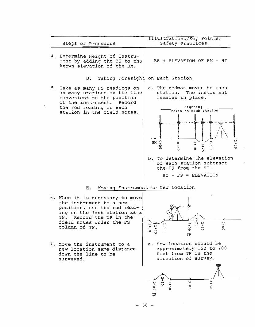
4. Determine Height of Instrument by adding the BS to theknown elevation of the BM.
BS + ELEVATION OF BM = HI
D. Taking Foresight on Each Station
+oo
. _ L-.----C-- - - - - - - '-------\ll ~ItBM~ 0 ':;: I-' '+"
o ~ 0 + ~o <:I 0 ~ 0
Sighting'----taken on each station
a. The rodman moves to eachstation. The instrumentremains in place.
5. Take as many FS readings onas many stations on the lineconvenient to the positionof the instrument. Recordthe rod reading on eachstation in the field notes.
b. To determine the elevationof each station subtractthe FS from the HI.
HI - FS = ELEVATION
w+oo
'"+V'o
'"+oo
TP
,..+V'o
,..+ ,..o +o '"V'
E. Moving Instrument to New Location
6. When it is necessary to movethe instrument to a newposition, use the rod read- ,ing on the last station as a:TP. Record the TP in the !field notes under the FS Icolumn of TP.
7. Move the instrument to anew location same distancedown the line to besurveyed.
a. New location should beapproximately 150 to 200feet from TP in thedirection of survey.
TP
- 56 -
Steps of Procedure I lustrat~ons Key Po~nts
Safet Practices
F. Taking Backsight on ~P
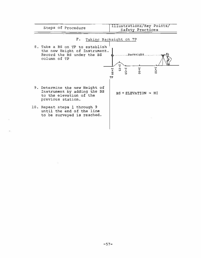
8. Take a BS on TP to establish Ithe new Height of Instrumen:1;'Record the BS under the BS ..........Backsi9ht. __ .• -----y:::column of TP ,~
~ .... -"- -"-LL.::llI.--Nl'VlV 1M W+ V1 + + +g ~ g ~
TP
9. Determine the new Height ofInstrument by adding the BSto the elevation of theprevious station.
10. Repeat steps 1 through 9until the end of the lineto be surveyed is reached.
-57-
BS + ELEVATION = HI
-
-- I
I
--5588'-~---~)
!I
I
~L
I
-
II
-, ,
!
I I
-
I I I I I
I
II
I I!,lI
1-
II
'--
--·1
- - .. _.
~-Iii
-i
-
;

ACTIVITY NO. XIII - Laying Out Contours
A. Objectives
1. To develop a contour map using the grid system.
2. To develop skill in keeping accurate notes onleveling for contour mapping.
B. Introduction
C~ntour mapping assist agriculturalists in planning drainage patterns, cropping systems, and controlling soilerosion. These maps show surface elevation at variouspoints throughout a parcel of land. Contour maps arealso used by horticulturalists in planning and layingout landscapes. In this activity you will make a contourmap of a land parcel.
C. Reference
1. Student Reference, Leveling & Land MeasurementPractices for Agriculture, February 1974, pp. 64-70.
D. Questions for Study
1. What is a contour?
2. What is a contour interval?
3. What is the contour interval of the following twoadjacent contour lines?
--98 feet
-106 feet
- ----------4. Contour lines on a map which are spaced closely to-
gether represent a surface having a slope.
5. Contour lines on a map which are spaced far apart rep-resent a surface having a slope.
-59-
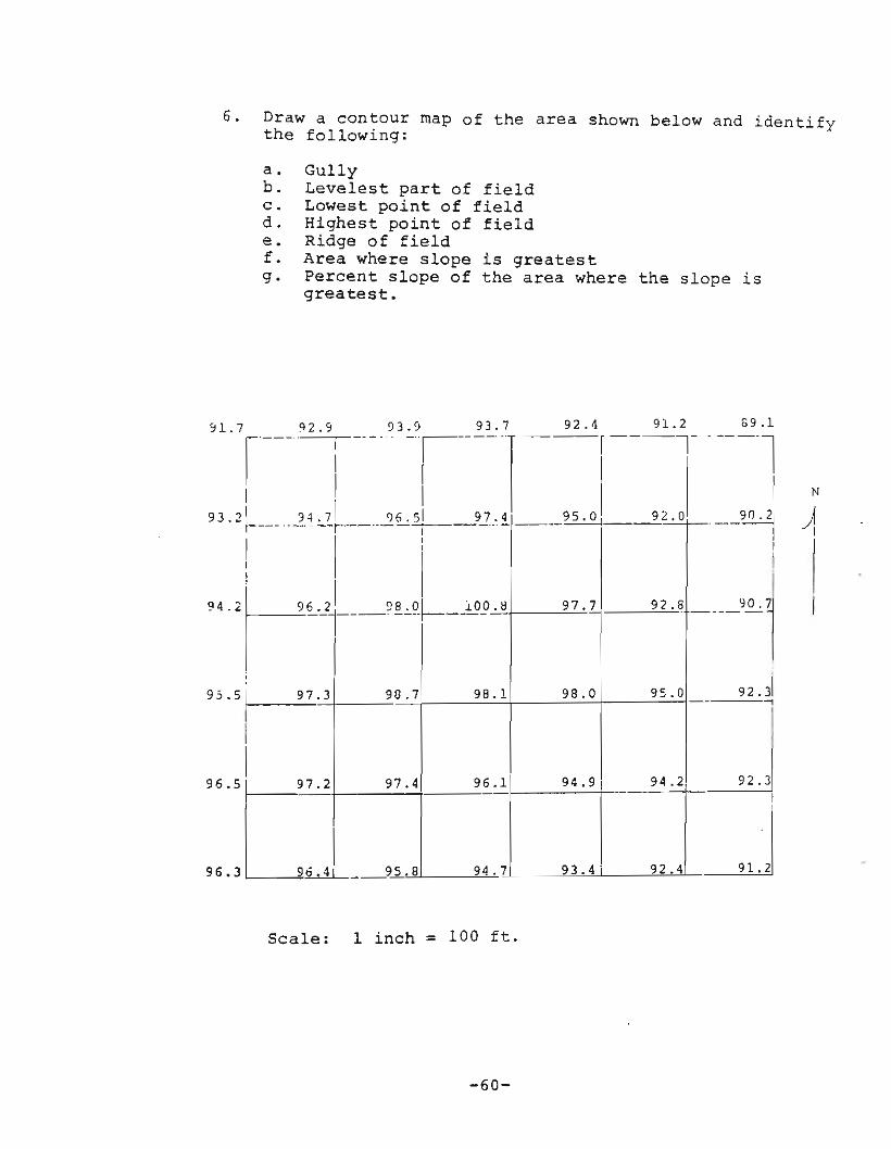
6. Draw a contour map of the area shown below and identifythe following:
a. Gullyb. Levelest part of fieldc. Lowest point of fieldd. Highest point of fielde. Ridge of fieldf. Area where slope is greatestg. Percent slope of the area where the slope is
greatest.
92.4 91.2 69.1r----T ------1
II N
95 ° 92 0 __90.21 )I I!
II- -'~1
92J..,
, H. 7 %.5 __'!......, _____.=l.___-'--'j--,---'--'-f---'---T I
~~'li----~.!l..:.Q.~-.JJli> .H97,1 92.6
I:
I97.3 90.7 98.1 98.0 95.0- -
II
96.1 94. 9 94.2I 97.2 97.4 ----
L.l 95.8 94.7 93.4, 92.4
~4. 2:
",I~-"t~- ""I!~'l93.2 1 I I 74
95.5
96.5
96.3
Scale: 1 inch = 100 ft.
-60-

JOB OPERATION NO.XIII - Laying Out Contours
STUDENT INSTRUCTIONS I
Follow the steps of procedure listed below toperform the contour mapping procedure.
Equipment:
-Tripod-Leveling instrument-Rod-Hammer
Steps of Procedure
Materials:
-Tall stakes (quantity varieswith field size)
II ustrat~ons Key Po~nts
Safet Practices
A. Establishin the Ba.Ql~ne
1. Establish an east-west lineand a north-south baselineas near as possible to twoboundaries of the field tobe contour mapped.
'" Baseline of~ field
B. Measun~nq Saseline Intervals
2. Starting from the cornerwhere the two baselines meet,measure with a steel tape at100 foot intervals along eachbaseline.
C. Plac ing G"uid" Stakes
3. Drive tall stakes into theground at each 100 footinterval. Each intervalshould be marked as shownin the illustration to theright.
4. Drive a second line ofstakes one grid intervaldistance (100 feet) in fromthe baseline.
-61-
A B C 0 E F G H
1_*
~ --~ABC 0 E F G H.
1 _----IO--IO-""*--'('
2 x x x x x x
3 x4 X
5 Jt--_-------.-J

Steps of ProcedureIllustrat~onslKey Po~nts
Safety Practices
D. Setting up Tripod Level
5. Set up the tripod levelsomewhere in the field wherethe entire field can be seenthrough the telescope tube.
E. Taking a Backsight
1
2
3
4
S
A B C D E F G
Il( H l( II: II: .,X X X X X x
tx J\x
H
H
fi
.J
ABC
6. Take a Backsight on a BenchMark or some other point ofknown elevation. If thereis not a Bench Mark or otherpoint of known elevation takea sighting on a permanentobject and arbitrarily giveit an elevation of 100 feet.
a. Rodman holds rod onBench Mark with the rodface clearly visibleto the instrument man.
o E F G H1 f n )( )C l! II )(!"
t~:""n; !BM
F. Takin a Foresight on Each Station
7. The rodman then moves toeach stake or station wherea rod reading is taken.Each station is identifiedby a combination of oneletter and one number thatcorresponds to its locationon the map. The elevationsof the various stations aredetermined by profileleveling. Each rod readingtaken is a Foresight and isentered under the FS columnof each station. Complete aset of field notes on contourmapping. Use the field notebook page found on page 65.
- 62 -
a. The stations not identified by stakes canbe located by the rodman "sighting in" hisposition by aligningappropriate pairs ofstakes.
ABC 0 E F G Hl __....---Of---lf--H--*-;;'
2 x * x x x x x3 - .. K•• ; I4 x ~ROWMn '
sights tolS 10-......--- align stake
Steps of Procedure ustrat~ons Key Po~nts
Safety Practices
G. Drawinq the Contour Map
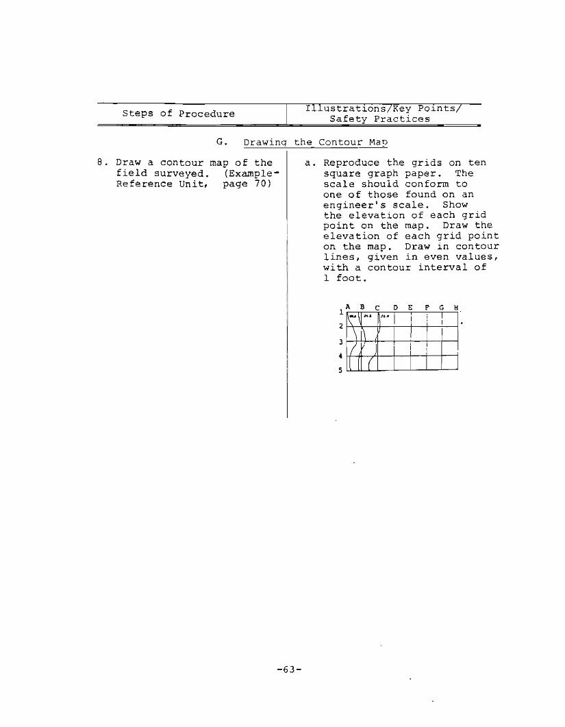
8. Draw a contour map of thefield surveyed. (ExampleReference Unit, page 70)
a. Reproduce the grids on tensquare graph paper. Thescale should conform toone of those found on anengineer's scale. Showthe elevation of each gridpoint on the map. Draw theelevation of each grid pointon the map. Draw in contourlines, given in even values,with a contour interval of1 foot.
-~~. .ft.•
! i .\ 1\ I II ! il ( I I
3
4
5
11. BCD E F G K
2
-63-

, _.
. , . ,
1-.
+--
_i.
:.....-I
_._. __ J _:. .
',co II II· t:-+-;....;.·:, II ,. 1'1 'i - ,'+I-'t-'
...:...:,~I.! i '-;,:1, --r'. 1 1 I ~ 1+ 1I, r-r-- I
-----n- , ", ,
-----
-_.
..~ .... '. -+-....,.., •. .;.. ~ .
---!-- -. --t-I t-- TT.. ---r,..--7- -:!--~. - '.
, --.1- . ri-:-'-r--r ,'"i-T,--,-
,.1-1::41:'.! .! .. ;. or, __ I ~
----=:..
, I '
, ,, , I •
, I , ,
· ! II· t ! r• I : I,
~:.:+-.;....~~~ .1-+~ -t'
.~.l.+:--+-~..;.-+~ ~- -+ , '
.I
!ItiIII,
,.~! •
~-Ji'-- - -f--;-.
: !-'-!-- _.~.~I-. ; ~ r-'-r-~:I.-,... , r--o--
.., ,
, ,, '
, '1 I
!1-.
;~. I _
. ,i II I'
I'Ililil-UkI. I .• ' '. ' ~- ."1-'- ,
, , -~-
. ~_._,-
• ....L...:._
, . . ; ..........'-t _.:._",.
-------.' -----'---
~-, '
--r--, --,- t..--+,l~o.-.~
.. --r-~---"
.......-.-1 ' , Ii! ..l---T-""'O"'- .
iH-,
, ', , ., ,
,~L++-1-+-+-'4 +-+-
I
~~II'~'I't'rrr·1 I ;' ,. , ,
TT~
=4 --+
--r-~r--'__ ;: ' ~ 1-.
~. ~
._.
-,"
"
:- "r
• --+--,-<-
••--- +-.' : ~-~ ,--.-- .-~ ~--:-'"-
, t :- •• I . j..
,
I
._----~
I
IiII
I
II,
-- L....
I
1--- - -!
_..
ii
!L .-65-
ACTIVITY NO. XIV - Determining Grades, Cuts & Fills
A. Objectives
1. To perform the grading operation.
2. To calculate cuts and fills on a land parcel for agiven slope.
B. Introduction
A field that is not uniform in grade or slope will have anuneven distribution of water when irrigated. Water willaccumulate in the low areas and result in decreased cropproduction. The agriculturalist in order to maintainmaximum production must construct his fields to a specificdegree of slope for drainage or movement of water acrossthe field at a desired rate. It is the purpose of thisactivity to provide you the opportunity to determine cutand fills on a field of a given slope.
C. Reference
1. Student Reference, Leveling & Land Measurement •Practices for Agriculture, February 1974, pp. 70-78.
D. Questions for Study
1. What is a grade or slope?
2. What is the percent slope of a field that falls 5feet in 200 feet of grade?
3. What is the difference between a cut and a fill?
4. If the elevation of a field is 8 feet at a certainlocation and the land grading plan calls for anelevation of 8.5 feet at the point, a __of .5 feet is required.
-66-
JOB OPERATION NO. xrv - Grading Procedure
I STUDENT INSTRUCTIONS I
Carefully follow the steps of procedure listedbelow to perform the grading operation.
Equipment:
-Tripod-Leveling instrument-Rod-Hammer
Steps of Procedure
Materials:
-Wooden stakes-Pencil-Field notebook
II ustrat~ons Key Po~nts
Safet Practices
A. _L_av iIl."g~O:.:u::.:t=-('...:..o=n..:t..:o:..;u:..:r=---G:..r=i...:.d----=o_n_A_F_i_e_ld
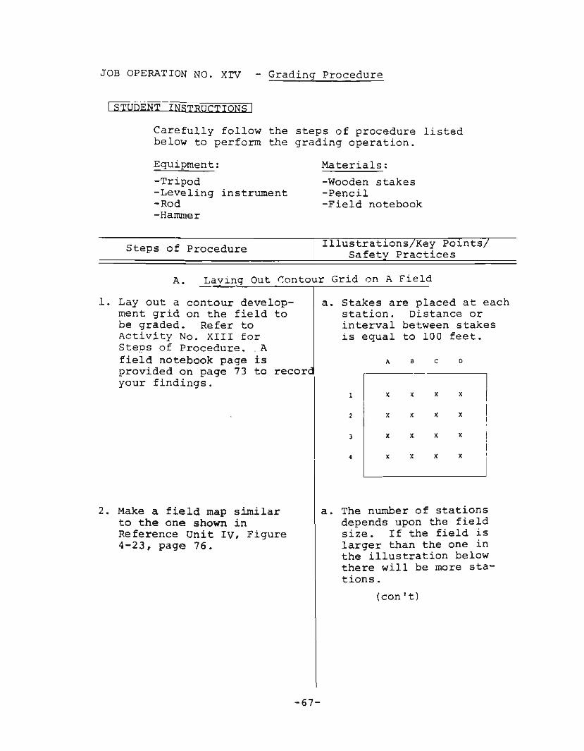
1. Layout a contour development grid on the field tobe graded. Refer toActivity No. XIII forSteps of Procedure•. Afield notebook page isprovided on page 73 to recoryour findings.
2. Make a field map similarto the one shown inReference Unit IV, Figure4-23, page 76.
a. Stakes are placed at eachstation. Distance orinterval between stakesis equal to 100 feet.
A a c 0
1 I x x x X
2 Ix x x X
3 L: x x x
• x x x
a. The number of stationsdepends upon the fieldsize. If the field islarger than the one inthe illustration belowthere will be more stations.
(con't)
-67-
Steps of Procedure Illustrat~ons Key Po~nts
Safety Practices
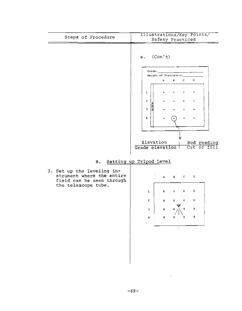
a. (Con't)
Grade:
Heiqt\t of lnstrut:le;-.cs
A 8 C 0
rr--'1 i I
+ • + •2 I + + + +
) + + + +
• + ~ + +
-v-=-_E-.-l_e_v_a....t_~_·o_n..,...,....,..._I~ROdGrade elevation Cut
readingor fill
B. Settin
cc
x
8A
2 X
1 X ::l) I x X/\\X x I·L_x_x_x_
1
3. Set up the leveling instrument where the entirefield can be seen throughthe telescope tube.
-68-
Steps of Procedure
c.
ustrat~ons Key Po~nts
Safety Practices
Taking Backsight
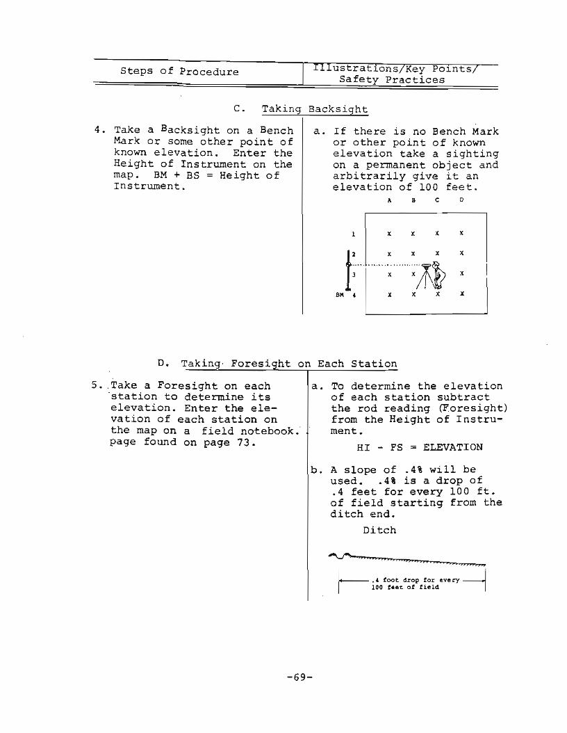
4. Take a Backsight on a BenchMark or some other point ofknown elevation. Enter theHeight of Instrument on themap. BM + BS = Height ofInstrument.
a. If there is no Bench Markor other point of knownelevation take a sightingon a permanent object andarbitrarily give it anelevation of 100 feet.
A 8 c o
1 X X X x I2 X X X x
··1 · · · : ID. Taking- Foresi ht on Each Station
S. ,Take a Foresight on each'station to determine itselevation. Enter the elevation of each station onthe map on a field notebook.'page found on page 73.
a. To determine the elevationof each station subtractthe rod reading (Foresight)from the Height of Instrument.
HI - FS = ELEVATION
b. A slope of .4% will beused. .4% is a drop of.4 feet for every 100 ft.of field starting from theditch end.
Ditch
""'-f'_........--."...................__
I .4 too~ drop tor e.very~r------- 100 t ••~ of tield ~
-69-
Steps of Procedure I ustrat~ons Key Po~nts
Safety Practices
E. Calculating Average Elevation
6. Calculate the average elevation of the field. Place theaverage elevation in the center of the map.
a. This is done by summingall the station elevationsand dividing by the numberof stations.
Sum of allelevations
Number ofStations
= AverageElevation
Average 2 =Elevation - .
F. Calculating
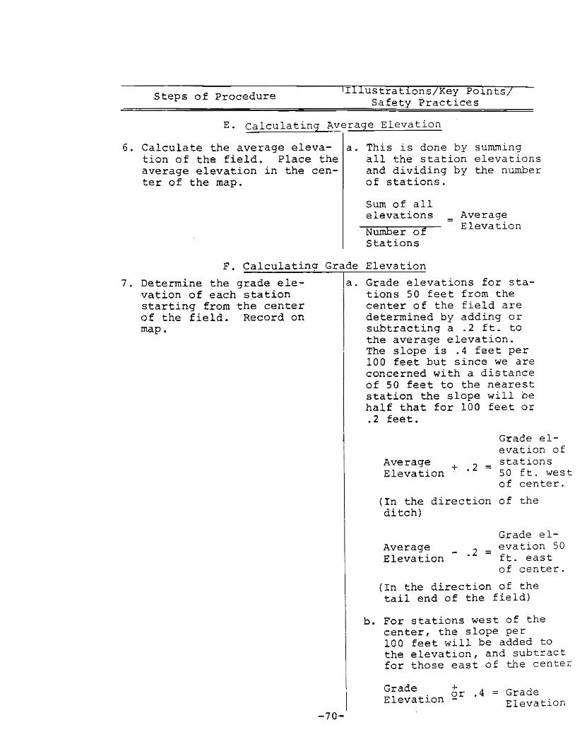
7. Determine the grade elevation of each stationstarting from the centerof the field. Record onmap.
Grade Elevation
a. Grade elevations for stations 50 feet from thecenter of the field aredetermined by adding orsubtracting a .2 ft. tothe average elevation.The slope is .4 feet per100 feet but since we areconcerned with a distanceof 50 feet to the neareststation the slope will behalf that for 100 feet or.2 feet.
Grade elevation of
Average = stationsElevation +.2 50 ft. west
of center.
(In the direction of theditch)
Grade elevation 50ft. eastof center.
(In the direction of thetail end of the field)
b. For stations west of thecenter, the slope per100 feet will be added tothe elevation, and subtractfor those east of the center
Grade +.4 = GradeElevation 2r Elevation
-70-

Steps of Procedure
G. Calculatin Cuts and Fills
8. Determine cuts and fillsat each station. Recordon map.
a. This is done by subtractingthe grade elevation at eachstation. If the elevationis larger than the grade,it will be a cut. If theelevation is smaller thanthe grade, it will be afill.
Grade _ Elevation =Elevation
Cutor
Fill
H. Marking Stakes at Each Station
Sum of Fills
9. Mark the rod reading elevation, grade elevation,and cut or fill taken ateach station on the upperpart of each stake.
I. Checkin
10. Check the balance betweencuts and fills.
-71-
/. . -- V Ro4 Readinq
ElevAtion - ~~l~.;:~
Grade Elevation / III I I i I ~cut or Fill
I, "': I \ Ii: ~ J\ .,
Il\'l . I',I' ,N ~ ,
-=-_._. --- ..-
ill Balance
a. An excess of cut over fillin a ratio o·f approximately1.2 to 1.6 is necessary toallow for compaction andequipment operator errors.To check this ratio, thecuts and fills are summed.The cut-fill ratio is determined by the followingformula:
s_urn__o_r_c_u_ts_ = cut/fillratio

Steps of ProcedureIllustrations/Key Points
Safety Practices
I. Checking Cut/Fill Balance (Con't)
b. If the cut/fill ratiocalculated is between1.2 and 1.6 there willbe enough earth fromthe cuts to fill thelower area of thefield. If a satisfactory ratio was notcalculated, all gradeelevations would haveto be lowered by .1and cut and fillsrecalculated.
J. Calculating Earth Moved
11. Calculate the total numberof cubic yards of earth tobe moved in order to levelthe field.
a.cubic yds.
:::c.:::uc.::t~/c.::f:.:i:.:l:.:l:.-.:r:..:a::..t::..J.::..·o:::-.:.(=.f..=t.!..)-:.:xc....:l:.:O:...:O=---=f..:tc:.-=.x:....:l:.:O:...:O'-f~t. ~ to be moved.27 yds/ft3
- 72 -
I ,
I
II
- I
-I
;
I
~-+- -
II• I I
-73-