studies of noise transmission in advanced …
TRANSCRIPT

STUDIES OF NOISE TRANSMISSION IN ADVANCEDCOMPOSITE MATERIAL STRUCTURES
Louis A. Roussos, Michael C. McGary, andClemans A. Powell
NASA Langley Research CenterHampton, Virginia 23665
1984 ACEE Composite Structures ConferenceSeattle, Washington
August 13, 1984
161

CONCERNSANDPOTENTIALPROBLEMSRELATEDTONOISETRANSMISSIONIN COMPOSITEFUSELAGES
The noise transmission characteristics of advanced composite material
structures must be taken into account early in the design phases of composite
fuselages so that the weight-saving advantage of composite construction will
not be compromised by high noise transmission and heavy add-on acoustic
treatments. Some of the noise transmission concerns and potential problems
related to advanced composite material fuselages are indicated in figure 1.
Noise from a variety of noise sources can enter an aircraft fuselage through a
number of paths or mechanisms. Noise from these sources is frequently
classified as being either airborne or structureborne. In many instances the
airborne and structureborne noises are highly correlated and indistinguishableonce inside the aircraft. The airborne noise transmission characteristics of
a fuselage can be either favorably or adversely affected by the use of
advanced composites materials depending on the frequency of the incident
noise. At low frequencies, a composite fuselage may transmit less noisebecause of increased stiffness. In the region where structural resonances and
damping control noise transmission, a composite fuselage may transmit eithermore or less noise depending on the damping characteristics of the materials.
At mid frequencies a composite fuselage should transmit more noise for an
equivalent stiffness design. Noise frequencies for which the lengths ofacoustic and structural waves coincide should be lower for compositeconstructions and therefore could allow more overall noise transmission for
most aircraft noise sources (upper mid frequency range). The effects of
composite construction on structureborne noise in the low and mid frequencies
are hard to generalize although noise problems may be found in the upper mid
frequency range because radiation efficiency is very high in the coincidenceregion.
AIRBORNE NOISESOURCE
/_/f --, "_ FUSELAGE
i VER
STRUCTUREBORNEVIBRATION/NOISE PATH
AIRBORNENOISE
TRANSMISSION
STIFFNESS MASSDAMPING COINCIDENCE
( I
I l
FREQUENCY
STRUCTUREBORNENoISELEvEL__
FREQUENCY
Figure I
162
RESEARCH PROGRAM
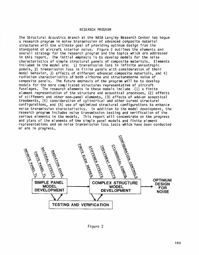
The Structural Acoustics Branch at the NASA Langley Research Center has beguna research program in noise transmission of advanced composite materialstructures with the ultimate goal of providing optimum design from thestandpoint of aircraft interior noise. Figure 2 outlines the elements andoverall strategy for the research program and the topics which are addressedin this report. The initial emphasis is to develop models for the noisecharacteristics of simple structural panels of composite materials. Elementsincluded in the model are: I) transmission loss in infinite anisotropicpanels, 2) transmission loss in finite panels with consideration of theirmodal behavior, 3) effects of different advanced composite materials, and 4)radiation characteristics of both airborne and structureborne noise of
composite panels. The future emphasis of the program will be to developmodels for the more complicated structures representative of aircraftfuselages. The research elements in these models include (I) a finiteelement representation of the structure and acoustical processes, (2) effectsof stiffeners and other non-panel elements, (3) effects of add-on acousticaltreatments, (4) consideration of cylindrical and other curved structuralconfigurations, and (5) use of optimized structural configurations to enhancenoise transmission characteristics. In addition to the model development, theresearch program includes noise transmission testing and verification of thevarious elements in the models. This report will concentrate on the progressand plans of the elements of the simple panel models and finite elementrepresentations and on noise transmission loss tests which have been conductedor are in progress.
SIMPLE PANELMODEL
DEVELOPMENT
\/
p
COMPLEX STRUCTURE IMODEL
DEVELOPMENT I
\/TESTING AND VERIFICATION I
OPTIMUMDESIGN
FORNOISE
Figure 2
163

INFINITE PANEL THEORY TRANSMISSION LOSS MODEL
In infinite panel theory the panel is modelled as a thin plate with infinite
area. For oblique incidence transmission loss, the incident sound is modelled
as a single plane wave that impinges on the panel at an arbitrary angle.Because the panel is infinite, the reflected and transmitted pressures are
also plane waves. The geometry of the transmission is shown in figure 3.
Since the intensity of a plane wave is linearly proportional to the mean
square pressure, the oblique incidence transmission loss, which is calculatedfrom the ratio of incident to transmitted intensities, reduces to the simple
relationship between incident and transmitted pressures shown in the figure.The ratio of incident to transmitted pressure is calculated from the
differential equation of motion of the plate: the general form of the
equation is given in the figure. The frequency at which the term in brackets
is a minimum is called the coincidence frequency and corresponds to a
wavelength resonance condition at which the trace wavelength of the incident
noise is equal to the free bending wavelength in the infinite plate. At
frequencies below the coincidence frequency, the first term within the
brackets, the so-called "mass law" term, governs the transmission. Above
coincidence the curve rises sharply and is a function mainly of the damping,which is represented by the loss factor in the equation in the figure. In
summary, the infinite panel theory transmission loss model is applicable only
in the mass controlled and coincidence frequency regions of transmissionloss.
Pi _ I _ _f cos e i---l+jPt L pc g (Dij, f. rl, e i, (l)i)]
pc
Pr
Pi
pc
---_w PLATE
DEFLECTION
TRANSMI SSI ONLOSS.
dB
MASS I COINCIDENCE
lFREQUENCY. Hz
Figure 3
1 64

TRANSMISSION LOSS TESTS OF LARGE PANELS
Facility and Method
To validate the infinite panel theory and experimentally establish the noise
transmission loss characteristics of large composite test panels, the panels
were mounted in the ANRD Transmission Loss Apparatus as partitions between twoadjacent rooms which are designated the source room and the receiving room.
Top and side views of the apparatus are shown in figure 4. In the source room
a diffuse field is established by two reference sound power sources. Sound is
transmitted from the source room into the receiving room only by way of the
test panel, which has a sound exposed vibrating area of 0.85 m by 1.46 m (2.8
ft by 4.8 ft). The test specimen is mounted in a steel frame which is
designed for minim_ structural flanking. The receiving room is acousticallyand structurally isolated from the rest of the building. A space and time
average of the sound pressure levels is taken in each of the rooms by amicrophone mounted at the end of a rotating boom. The microphones measure thepanel's noise reduction, which is defined as the difference between the
measured average sound pressure leve|s in the source and receiving rooms.Noise reduction includes characteristics of the test specimen as well as room
characteristics. Trans,_ission loss, which is a function of the properties ofthe test specimen only, is calculated from noise reduction by correcting forshe absorption in the receiving room as well as for the non-diffusivity ofboth rooms.
TOP VIEW
ACCESS DOORS DOORSIDE VIEW
Figure 4
165

TRANSMISSION LOSS TESTS OF LARGE PANELS
Panel Configurations
A total of 28 fiber-reinforced composite panels were tested. Twelve of these
panels were of tape construction, fourteen were of fabric construction, and
two were of sandwich construction with fabric composite skins and syntactic
(microballoon-filled epoxy) cores. The tape panels were made by bondingtogether several plies of unidirectional fibers. Each ply has a "ply angle"
which refers to the angle at which the fibers are laid up in relation to thelonger boundary of the panel. Thus, a 0° or 90° ply has its fibers parallel
to one of the boundaries. The panels with fabric construction were similarly
made by bonding several plies together. Since a fabric ply consists of two
sets of fibers woven perpendicular to each other, two ply angles are
associated with each ply. Also, in one fiber direction called the fill
direction, the fibers are straight, while in the opposite warp direction, the
fibers bend up and down as they weave around the straight fibers. For a
0°/90 ° ply, the warp of the fabric was oriented in the direction of the longer
boundary of the panels, i.e., in the 0° direction. Descriptions of ply
material, ply angle lay-up, thickness, and number and type of plies for eachpanel are given in figure 5. As can be seen in the figure, three ply
materials were tested (graphite-epoxy, Kevlar*-epoxy, and fiberglass-epoxy)for both tape and fabric construction, for two thicknesses, and for various
ply angle lay-ups.
*Kevlar aramid fibers, manufactured by E. I. du Pont de Nemours & Co., Inc.
TAPE PLY ANGLE CUNFIGURATLONS
G/E, K/E, ANU FIE
8 PLILS (0.i0 CM) ... _45, 0/90
ib PLIES (U-2U CM) ... ±45, 0/90
FABRIC PLY ANGLE CUNFIGURAILUNS
G/E, K/E, AND F/E
4 PLLES (0.10 CM) ... ,45, 0/90
8 FLIES (O.2U CI_}... _45, 0/90/t45
UTHER GIE (UI90) FABRIC _ONFIGURATIDNS
3 PLIES (0.10 CM)
6 PLIES (O.20 Cm)
6 PLLES w/O.iO CM SYNTACTICCORE
6 PLLES w/O.20 CM SYNTACTICCURE
Figure 5
1 66
TRANSMISSIONLOSS TESTS OF LARGE PANELS
Typical Results
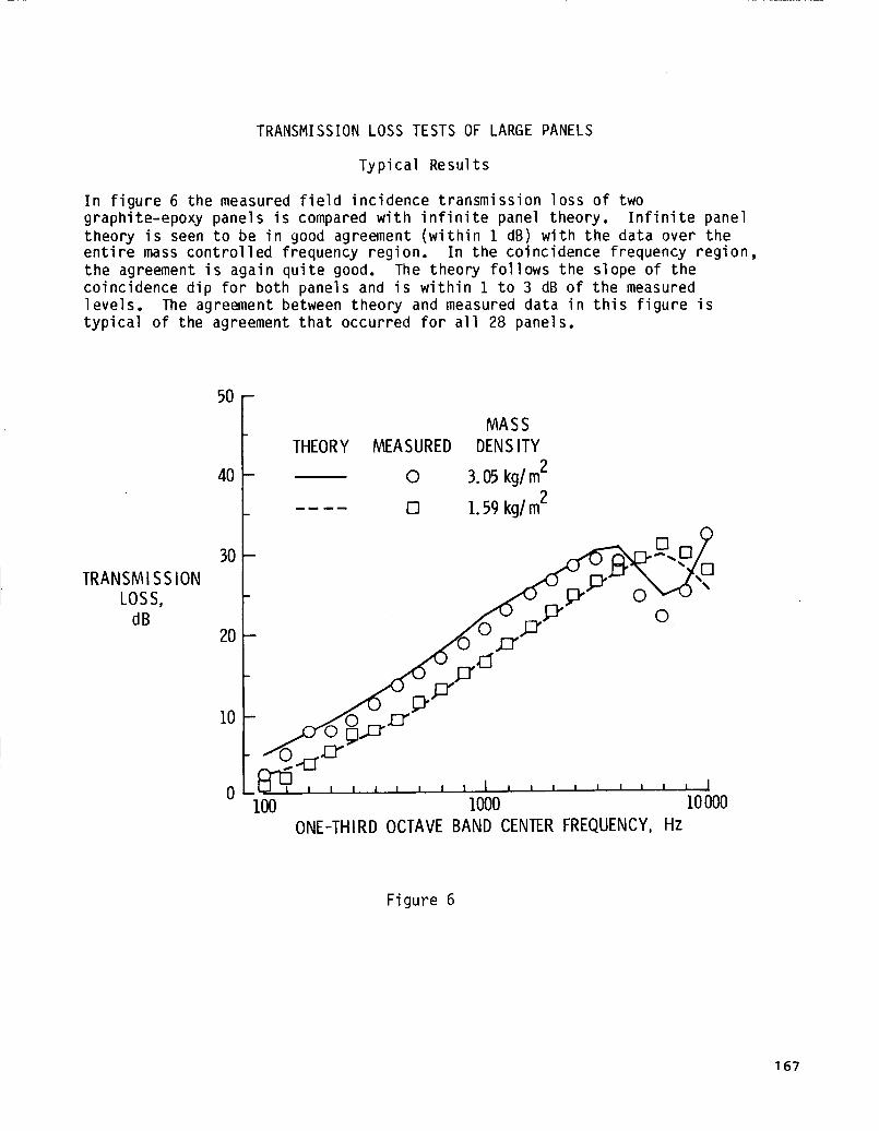
In figure 6 the measured field incidence transmission loss of twographite-epoxy panels is compared with infinite panel theory. Infinite paneltheory is seen to be in good agreement (within I dB) with the data over theentire mass controlled frequency region. In the coincidence frequency region,the agreement is again quite good. The theory follows the slope of thecoincidence dip for both panels and is within I to 3 dB of the measuredlevels. The agreement between theory and measured data in this figure istypical of the agreement that occurred for all 28 panels.
TRANSMI SS ION
LOSS,dB
50-
4O
3O
2O
I0
0
MASS
THEORY MEASURED DENSITY2
O 3.05 kg/m2
[] I. 59 kg/m
_i I I I I I I I I I I I I I m I i I m I
I00 I000 I0000
ONE-THIRD OCTAVE BAND CENTER FREQUENCY, Hz
Figure 6
167

TRANSMISSION LOSS TESTS OF LARGE PANELS
Overall Prediction Ability
The noise transmission loss prediction ability of infinite panel theory for
the large composite panels is indicated in figure 7. The prediction error,the difference between predicted and measured transmission loss, is plotted
for 14 of the 28 composite panels. The frequency scale on the abscissa has
been normalized by dividing by the critica] frequency, the lowest frequency
for which coincidence occurs. The prediction error in the mass controlled
region (f/f-critical < I) is seen to be generally less than ±3 dB. In the
coincidence region, the error is somewhat greater (generally within 26 dB).
This is because the stiffness and damping properties used in the infinite
panel theory model were only rough estimates and these properties govern thetransmission loss in the coincidence region.
PREDICTION
ERROR,
dB
2°f10
0
,-, o o o o m,@)o_°t o '-' o o°OoU '-'- 6) 0
-'°t-20 I
.0]
0
t. i I i J titI t t I _ t ttl_ i i t t
.] ]
FREQUENCY RATIO, F/F-CRITICAL
I
]0
Figure 7
168

FINITE PANEL THEORY DEVELOPMENT
For low frequency noise, the dimensions of the transmitting panel arecomparable to or smaller than the sound wavelengths so that boundary effectsare important. Therefore, for this case, a new finite panel noisetransmission theory, as indicated in figure 8, has been developed. In thistheory the panel is modelled as a rectangular plate simply supported in aninfinite rigid baffle. The incident acoustic pressure is modelled as a planewave impinging on the plate at an arbitrary angle of incidence. The incident,reflected, and transmitted pressures are approximated by the blocked pressurewhich is ass_ed to be much greater than the reradiated pressure. Thisassumption allows the plate vibrations to be calculated by a normal-modeapproach. The Rayleigh Integral is used to link the plate vibrations to thetransmitted acoustic pressure. The incident and transmitted acoustic powersare calculated by integrating the incident and transmitted intensities overtheir appropriate areas, and transmission loss is calculated from the ratio ofincident to transmitted acoustic power.
• RECTANGULAR PLATE SIMPLY SUPPORTED
IN INFINITE BAFFLE
• BLOCKED PRESSURE ASSUMPTION
Pi + Pr - Pt _ 2Pi
• MODAL SOLUTION FOR PANEL VIBRATIONS
• RAYLEIGH INTEGRAL WITH FAR-FIELD
APPROX I MATI ONS
• INTEGRATION OF INTENSITIES FOR
INCIDENT AND TRANSMITTED ACOUSTICPOWER S
,Nc,DE.IACOUST,CPOWER• T. L. = 10 log vI_RANSMITTED ACOUSTIC POWEnj-/
Figure 8
169

FINITE PANEL THEORY DEVELOPMENT
Radiation Directivity Results
An example of the use of the model for calculating radiation directivity isshown in figure 9. Plotted here is the variation of transmitted intensity inthe far field of a 36-cm by 20-cm by O.Ol-cm graphite-epoxy panel for a planewave incident on it at a polar angle of 45 ° and an azimuthal angle of 0°(paral]el to the 36-cm side of the plate). The ply angle lay-up of the panelconsisted of 8 alternating +45 ° and -45 ° plies laid up symmetrically aboutthe midplane. Transmitted intensity was calculated for two frequencies, 500Hz and 3000 Hz. The sample results show that as frequency increases, more ofthe transmitted sound becomes concentrated at a transmitted angle equal to theincident angle. The results showing the variation of transmitted intensitywith azimuthal angle display an example of symmetry which helps reduceintegration time. With an incident azimuthal angle of @i = 0°, symmetryoccurs about @ = 0°. Though not shown, for an incident azimuthal angle of@i = 90°, symmetry occurs about _ = 90 ° . And, for an incident polar angleof 0 i = 0°, symmetry occurs about both _ = 0° and _p = 90 °. Studying thesetransmitted intensity radiation patterns is thus seen to aid in both theunderstanding of the physics of the problem and the understanding of thenumerics invo|ved in calculating transmission loss.
EFFECT OF FREQUENCY ON TRANSMITTED INTENSITY
INTENSITY VARIATION
WITH POLAR ANGLE
i=45 °, ¢i=0 °
I
/.,,''""J ,.,//
/ /
II//111 t111 III
i I I
i I i_, j.,," ...,;]ii II 111111 4_i _/
INTENSITY VARIATION
WITH AZIMUTHAL ANGLE
500 Hz
5000 Hz
?4..._., I ,,:
Figure 9
170

FINITE PANEL THEORY DEVELOPMENT
Prediction of Effect of Ply Angle and Incidence Angle on Transmission Loss
In a composite panel the flexural rigidity moduli will be different indifferent directions depending on ply angle lay-up. Therefore, panels withdifferent ply angle lay-ups or with different orientations with respect to theincident noise could have markedly different low frequency noise transmissioncharacteristics. The effects of ply angle and incidence angle on transmissionloss have been calculated for a 36-cm by 20-cm by O.lO-cm graphite-epoxy paneland the results are shown in figure I0. The curves showing ply angle effect,which were calculated for the case of normal incidence, indicate that a panelmade of +45o/-45 ° plies has significantly higher (6 to 14 dB) transmissionloss in the stiffness controlled low frequency region than a panel made of0o/90 ° plies. In the frequency range immediately following the fundamentalresonance of the +450/-45 ° panel, the 0o/90 ° panel has 2 to 9 dB moretransmission loss. Since the panels weigh the same, the transmission losscurves merge together in the high frequency mass controlled region. Incomparing the transmission loss for the +45o/-45 ° panel for two differentangles of incidence, very little difference (less than 2 dB) is found in thestiffness and resonance controlled regions, while in the mass controlledregion the normal incidence curve rises up to a maximum of 3 dB above the 45 °incidence case. These predictions indicate that the ability to tailor theply angle lay-up of a composite panel can significantly affect the lowfrequency noise transmission characteristics, and the effect of varying theangle of incidence is not as important an effect at low frequency. Furtherstudy is needed to fully understand the ply angle effect and to determine theeffect of varying the azimuthal incident angle.
TRANSMISSION LOSS OF FINITE COMPOSITE PANELS
36cm. x 20cm. x 0.10cm. GRAPHITE-EPOXY PANEL
PLY ANGLE EFFECT INCIDENCE ANGLE EFFECT
PLY ANGLE40
40_,\ 0°,90 ° __l'
'" ..... +45, °- 45 ° '_
30 _ 30i _ii _
TRANSMISSION !i " _LOSS, ,/
da _, i20 20
I I / I l/ lOlO /
/
,,i f0 ,_r I I I Jlltll _ ' 0 _lltll
3.101 102 103 3.103 3.101
FREQUENCY,Hz
INCIDENCE ANGLE
__ 45 °
..... 0 O
/
i/
t//
i/
i_[ //
t" 1 I /
/' / I/ /
/,/
II II
I
102 103 3.103
FREQUENCY,Hz
Figure 10
171

FINITE PANEL THEORY DEVELOPMENT
Design Comparison
The analytical model has been used to investigate the effect on noisetransmission of replacing a typical general-aviation type aluminum skin witheither graphite-epoxy or Kevlar-epoxy skins. The design comparison presentedhere is based on equal critical shear load for the composite and aluminumpanels. The panels were assumed to be approximately 36 cm by 20 cm withsimply supported boundary conditions. The composite panels were assumed to beof tape construction with each ply being 0.013 cm thick. The critical shearload was first calculated for the aluminum panel which was assumed to be 0.I0cm thick. Each composite panel was then designed for the minimum thicknessnecessary for its critical shear load to be greater than or equal to that ofthe aluminum panel. The incidence sound is assumed to impinge at an angle of60 ° . In figure 11, it can be seen that because of their higher fundamentalfrequencies, the graphite-epoxy and Kevlar-epoxy panels have over 12 dB moretransmission loss at the aluminum panel's resonance (79 Hz). The increase intransmission loss over the aluminum panel is about 4 dB at the lowestfrequencies plotted. In the high frequency mass controlled region, thegraphite-epoxy and Kevlar-epoxy panels have about 3 to 4 dB less transmissionloss because they would be about 34 percent lighter than the aluminum panel.Such transmission loss characteristics indicate that composites may bebeneficial for low frequency noise transmission problems at or below theresonance of conventional aluminum panels.
TRANSMISSIONLOSS.
dB
PANEL SIZE 20cm x 36cm; EQUALCRITICAL SHEARLOAD50-
4O
3O
2O
l i i i i i i lllJ
0 i0 I00
I0
-- ALUM, 0.101 cm, 2.81 kg/m2
G/E, 0.114cm, 1.78kg/m 2
K/E, 0.140cm, 1.89 kg/m2
_ I i I llLI I I I I I IIll
1000 10000
FREQUENCY,Hz
Figure 11
172
TEST PLAN FOR FINITE PANELS
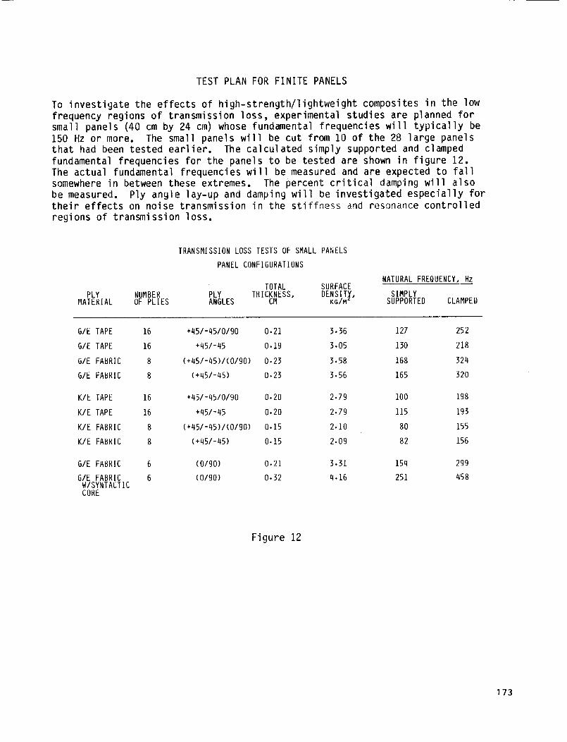
To investigate the effects of high-strength/lightweight composites in the low
frequency regions of transmission loss. experimental studies are planned for
small panels (40 cm by 24 cm) whose fundamental frequencies will typically be
150 Hz or more. The small panels will be cut from I0 of the 28 large panels
that had been tested earlier. The calculated simply supported and clamped
fundamental frequencies for the panels to be tested are shown in figure 12.The actual fundamental frequencies will be measured and are expected to fall
somewhere in between these extremes. The percent critical damping will also
be measured. Ply angle lay-up and damping will be investigated especially fortheir effects on noise transmission in the stiffness and resonance controlled
regions of transmission loss.
TRANSMISSIONLOSS TESTS OF SMALLPANELS
PANEL CONFIGURATIONS
NATURAL FREQUENCY, HzTOTAL SURFACE
PLY NUMBER PLY THICKNESS, DENSITY, SIMPLYMATERIAL OF PLIES ANGLES CM KG/M_ SUPPORTED CLAMPED
GIE TAPE 16 +45/-45/0/90 0.21 3-36 127 252
G/E TAPE 16 +45/-45 0-19 3.05 130 218
G/E FABRIC 8 (+45/-45)/(0/90) 0-23 3.58 168 324
G/E FABRIC 8 (+45/-45) 0.23 3.56 165 320
K/E TAPE 16 +45/-45/0/90 0.20 2.79 100 198
K/E TAPE 16 +45/-45 0.20 2.79 115 193
K/E FABRIC 8 (+45/-45)/(0/90) 0.15 2.10 80 155
K/E FABRIC 8 (+45/-45) 0.15 2-09 82 156
G/E FABRIC 6 (0/90) 0.21 3.31 154 299
G/E FABRIC 6 (0/90) 0.32 4.16 251 458W/SYNTACTICCORE
Figure 12
173
FINITE ELEMENT MODEL DEVELOPMENT
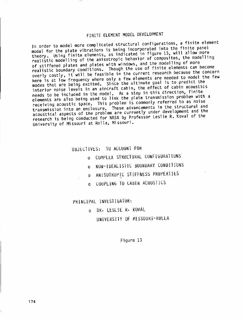
In order to model more complicated structural configurations, a finite elementmodel for the plate vibrations is being incorporated into the finite paneltheory. Using finite elements, as indicated in figure 13, will allow morerealistic modelling of the anisotropic behavior of composites, the modellingof stiffened plates and plates with windows, and the modelling of morerealistic boundary conditions. Though the use of finite elements can becomeoverly costly, it will be feasible in the current research because the concernhere is at low frequency where only a few elements are needed to model the fewmodes that are being excited. Since the ultimate goal is to predict theinterior noise levels in an aircraft cabin, the effect of cabin acousticsneeds to be included in the model. As a step in this direction, finiteelements are also being used to link the plate transmission problem with areceiving acoustic space. This problem is commonly referred to as noisetransmission into an enclosure. These advancements in the structural andacoustical aspects of the problem are currently under development and theresearch is being conducted for NASA by Professor Leslie R. Koval of theUniversity of Missouri at Rolla, Missouri.
(]t_JECTIVES:
0
0
0
0
IU ACCOUNT FOR
CO_IPLLX STRUCTURAL CUNFIGURATIUNS
NUN-IDEALISTIC BOUNUARY CUNDITIUNS
ANISOTRUHIC STIFFNESS PRUPERI[LS
CUUPLIN6 TU CABIN ACUUSTICS
PRINCIPAL INVESIIBATUR:
o DR. LESLIE R. KOVAL
UNIVERSIIY OF I_ISSOURI-RULLA
Figure 13
174

STRUCTUREBORNE NOISE RADIATED BY COMPOSITE PANELS
Until recently, both the analytical and experimental research programs on thenoise radiative properties of composite materials have been devoted almostexclusively to the study of airborne sound transmission through compositestructures. Present and future research in this area includes a comprehensivestudy of the structureborne noise radiative properties of these materials.Evidence of the extreme differences in these two sound generating mechanisms(airborne vs. structureborne) can be predicted analytically and measuredexperimentally in terms of the acoustic source directivity, the acousticradiation efficiency, and the complexity of the acoustic near field. Figure14 shows the large difference in the acoustic radiation efficiency for theairborne and structureborne sound radiated by a rectangular sheet ofplexiglass. Similar differences in the airborne and structureborne noiseradiative properties of panels constructed with composite materials areexpected.
CHARACTERISTICS OF STRUCTUREBORNE SOUND RADIATIONIN TERMS OF THE ACOUSTIC RADIATION EFFICIENCY o :
O = ---
AIRBORNE NOISESOURCE
•/_. --..\ FUSELAGE
l-jJ,,/]l "
VER
STRUCTUREBORNE ""----.JVIBRATION/NOISE PATH
II
pc <v=>,,, • Area
RRDIRTION EFFICIENCY (dB)
___0_.I_I__RIRIBORNE -- STRUCTUREBORNE
-ZO
-30
-40O
I I I " I
200 400 600 800 1000
FREQUENCY (Hz)
Figure 14
175

METHOD FOR SEPARATING AIRBORNE AND STRUCTUREBORNE NOISE IN COMPOSITE PANELS
Figure 15 illustrates a new measurement method for separating airborne andstructureborne noise radiated by aircraft-type panels which is underdevelopment. The method isan extension of the two-microphone cross-spectralacoustic intensity measurement method combined with conventional methods formeasuring the space-averaged mean square surface velocity of the structure.Both analytical and experimental studies are planned, with the aim ofdeveloping a comprehensive set of user guidelines for this method. Themeasurement method will be applied to panels constructed of both conventionalaircraft materials and advanced composites. Parameters which will be studiedinclude the frequency range of excitation, relative magnitude and phases ofthe combined airborne and structureborne inputs, and the effects of addedstructural damping.
ACOUSTICINPUT
COMBINEDAIRBORNEANDSTRUCTURE-BORNENOISE
.............
" ACOUSTICINTENSITY" SURFACEVELOCITY
riV ° RADIATIONEFFICIENCY LEVEL,dB
................................. ]
,,,;PATE,NT DISCLOSURE 3-15-82f
• [[[I[111111I
I oAPPLICATIONS I
CONVENTIONAL MATERIALS
ADVANCED COMPOSITES
[
I ................
• PARAMETERS ""
FREQUENCY RANGE
RELATIVE MAGNITUDE
RELATIVE PHASE
ADDED DAMPING/I IIIIII I I
Figure 15
176

S
NOISE TRANSMISSION I N STIFFENED COMPOSITE STRUCTURES
F u t u r e research w i l l a l s o i n c l u d e s t u d i e s o f more compl icated composite s t r u c t u r e s . It i s expected t h a t b o t h a n a l y t i c a l and exper imenta l s t u d i e s o f t h e n o i s e r a d i a t i v e p r o p e r t i e s o f b u i l t - u p composite panels, such as t h e panel shown i n f i g u r e 16, w i l l be undertaken. P resen t l y , t h e a n a l y t i c a l s tudy o f n o i s e t ransmiss ion through composi te cy1 i n d e r s i s be ing updated by P ro fesso r Koval t o i n c l u d e t h e e f f e c t s o f frames and s t r i n g e r s . Parameters which w i l l be s t u d i e d i n c l u d e t h e geometry o f t h e s t i f f e n e r s (e.g. shape, s i z e and spacing) and t h e methods o f a t t a c h i n g t h e s t i f f e n e r s t o t h e panels (e.g. f a b r i c a t e d , adhesive bonded, r i v e t e d ) .
TIFF SIZ SHI
_ _ - -
'ENER GEOMETRY STIFFENER ATTACt E FABRICATED WITH P 4PE ADHESIVE BONDING
SPACING RIVETED
F i g u r e 16
iMENT ANEL
177

SUMMARY/PROGRAMSTATUS
Significant progress has been made in the program to determine noise
characteristics of advanced composite material structures. Theory has been
developed and verified for noise transmission loss of infinite panels which
can have anisotropic stiffness characteristics. Similarly, theory has been
developed and is being experimentally verified for orthotropic finite panels.
An oblique incidence model of that theory is currently operational and a
random incidence model is being programmed. Progress is also being made under
a grant with Prof. Koval at the University of Missouri-Rolla to develop finite
element models to account for added stiffness and coupling to acoustic
volumes. A study is under way to determine radiation characteristics for
airborne and structureborne noise and to separate those components in mixed
situations. Finally, test plans to determine transmission loss
characteristics of stiffened composite panels are being made with the
cooperation of the Army Structures Laboratory at Langley Research Center. The
successful completion of this program should make it possible to designcomposite structures with noise attenuation characteristics as good as current
aluminum structures and which still provide the weight savings anticipated for
equal stiffness designs. (See fig. 17.)
• ANISOTROPIC INFINITE PANEL THEORY DEVELOPED AND VERIFIED.
• ORTHOTHROPIC FINITE PANEL THEORY DEVELOPED, OBLIQUE INCIDENCEMODEL OPERATIONAL, RANDOM INCIDENCE MODEL BEING PROGRAMMED,VERIFICATION IN PROGRESS.
• FINITE ELEMENT MODEL DEVELOPED FOR SIMPLE PANELS, STIFFENEDPANEL MODEL BEING DEVELOPED AT U. MISSOURI-ROLLA.
• PROGRAM TO DETERMINE RADIATION CHARACTERISTICS FOR AIRBORNEAND STRUCTUREBORNE NOISE INITIATED.
• TRANSMISSION LOSS OF STIFFENED PANELS TO BE INVESTIGATED.
Figure 17
178