studies of ship maneuvering 'response to propeller and rudder actions
TRANSCRIPT
"DDC
STUDIES OF SHIP MANEUVERING ý
by C. LincolnCrane, Jr NAew Associate Member uStevens Institute of Technology, Hoboken, New Jersey;presently Marine Designer, Tanker DepartmentEsso International, Inc., New York, New York
ABSTRACT
)'An attempt is made to extend ship-maneuvering analysis for application at low ship speeds.Captive-modol experiments are made te N-ast'gate effects of non-equilibrium propellerspeeds on rudder force and effective thrust. Other experiments are made to explorefirst-order effects of very large drift angles and pure yaw rotation on hull hydrodynamicreactions. The experimental results, together with previous rotating-arm data, areapplied In motion equations, accounting for both extreme propeller actions and the occur-
rence of large drift angles and turning rates. Also included are propulsion and ruddertime lags, and the influence of uniform water current on ship trajectory. The equationsare programmed for computation, and ship response to a simple docking maneuver is pre-dicted. The computation is repeated several times to examiie sensitivity of ship motionsand trajectory to variations of operating parameters, namely, maximum reverse propellerspeed, engine response time, and water-current direction.
INTRODUCTION
Upon entering pilot waters from seaward, a ship's control problems change, In nature,becoming Increasingly difficult until maneuvers are concluded (successfully or oLherwise)at dockside, anchorage, or mooring. Throughout this period, control of ship's trajectory
and speed must be sufficient to assure safe passage through channels, bridges, and locks;and to avoid collisions with other vessels.
Unfortunately, when danger of collision or grounding is greatest., a speed otherwise"1"prudent" for navigation can be too slow for adequate directional control. This isbecause steady hydrodynamic forces depend on the square of ship speed, while externaldisturbances do not. A reduction to one-quarter speed, fc- example, will cut rudderforce to one-sixteenth, but will not diminish the adverse effects of wind and current.
Other ship characteristics contribute to the problem. First, rudder forces of a single-screw ship depend heavily on propeller speed. Second, large merchant ships have smallthrust-to-mass ratios, hence they respond sluggishly to propeller actions. And third,lightly loaded merchant ships have large ratios of above-water to below-water surfacearea, causing wind effects to be accentuated.
These factors combine to cause frtquent saturation of propeller and rudder forces. Some-times control is quite inadequate. Then, auxiliary forces such as tugs, bow-thruster,or anchor must be called upor.
The simplified motion equations used In most studies of ship control provide satisfactorypredictions of maneuvers under cruising (constant throttle) conditions, but are notsufficiently general to treat many real control problems, such as those which occur atlow ship speeds.
a 4Controllability surveys by Norrbtn,1 Ede and Crane,e Williams and Noble,*' Goodman, andAbkowitz5 discuss the usual forms of equations and their solutions. None Include propeller-speed changes, wind force, or water-current effect. Saunders, and more recently Hawkins,'have discussed special low-speed maneuvers without using equations of motion, Crane, Urar'and Chey' have formulated motion equations for mooring and docking maneuvers of a destroyerand a submarine. But most efforts on non-equilibrlum propeller effects have concentratedon ship-stopping. These works are summarlzed in Reference 9. Papers By English," Hawki.,,Stuntz and Taylor, and others treat bow-thrusters and other maneuvering-propulsion
iv-B-44Repoduced bý the7CLEARINGHOUSE .for Federal Scientific & TechnicalInformation Springfield Va. 22151
4.i

devices (tiPD) but these do not include MPD forces In maneuvering analyses.
The present work is a,, attear.t to extend the generality of ship-maneuvering analysis toinclude engine-maneuver and water-current effects and Introduce the possibilities of verylarge drift angles and space turning rates. Equations of motion are formulated fortranslation and rotition of a sjrfar.e ship maneuvering In a reference frame which Isfixed with respect to a moving -.' r,%-, (the water current). The Independent shipvariables comprise prcepeller spvea ,onc. rudder angie. :he equations are solved .. Ithrespect to the coordihAte frame moving with the water, and the solution Is transi.rmedto a fixed coordinate frame. Resultant ship velocity Is integrated to obtain ship'sposltion and orlentatic-. at any time. Water current Is a parameter, and is made zerowhen discussing other effects.
Coefficients of the equations are obtained from experiment, calculation, and existingdata. Strong couplings among ship speed, propeller speed, and rudder angle (at maneuv-ring speeds) are Investigated by captive-model tests on straight path in a towing tank.Indications of hydrodynamic reactions to very large drift angles and to pure yaw rotationare obtained experimentally. Numerical Integrations are performed by digital computer.
A few examples of computed maneuvers are given to Iflustrate uses which can be made ofmore general analyses of ship maneuvering. Using the computation procedure developed,the sensitivity of ship response to particular ship pa-ameters Is studied for a simpleship-docking maneuver.
This project was sponsored by the Bureau of Ships General Hydrumechanics Research Programunder Contract Nonr 263(63) and technically administered by the David Taylor Model Basin.
EQUATIONS OF MOTION - GENERAL
General Form of Motion Equations
Differential equations describing the motion of a ship are written with respect to areference frame rotating with the ship's axes, the origin of which is chosen coincidentwith the ship's center of mass (see Figure I, following page).
-. dVm d m(~+ uX) N -* T i + ux I~ w1dt
where F sum of all external forces acting
I N sum of ili external moments acting
-V velocity of ship center-of-mass relative to the water
angular velocity of ship (ship's axes)
I i ship inertia " ;sor
All vectors can be expressed in rotating (ship axes) coordinates. For a surface ship
+ In calm ter, these vector equations are reduced to three Cartesian equations by apply-U J I . ing t ollowing siimplifylng assumptions:
I . sn SIIEIT[VO Ship Is constrained to move in its lateral plane (i.e., the it.y-plane),
D 'hlWCtiflQ which Is horizontal.
VIAN~1-Ms . Center of mess is In the principal plane of symetry of the hull.
as.s and center of mass are constant.
* j Products of Inertia are zero.
8131318 'AA" stAtlV
I IV-B-45II
• -.

Cu P
7//
yz
6• FIGURE I. REFERENCE FRAMES
IV-B-6-46

Then,
m(6- rv) -X m(v + ru) -Y I ruN (2)z
where X and Y represent summations of unbalanced external forces acting In the xand y directions, and N the summation of unbalanced moments about the z-axis.
External forces arise from hydrodynamic reactions to hull motion, rropeller and rudderactions, aerodyn lIc reactions on hull structure, and all other forces which may beapplied by waves, bow-thruster, anchor chain, tugboat, mooring lines, etc. In thisanalysis, only hull hydrodynamic and propeller-rudder forces are Included. In succeedingsections, their contributions to X, Y, and N are considered.
Reference Frames
It Is usually desirable to c€scribe low-speed maneuvers relative to an inertial refer-ence frame fixed in the earth. However, the motion equations and solution are greatlysimplified if referred to a coordinate frame fixed in the ship, with subsequent trans-formation of solutions to the desired reference frame (Figure 1).
With a uniform water current, an additional (intermediate) reference frame is useful.The additional frame maintains the same orientation as the fixed frame` but moves withthe steady velocity of the uniform water current. In computation, the first transforma-tion of the solution is from ship axes to intermediate axes. The sýcond transformationsimply adds the water-current velocity components, to obtain motions relative to thefinal desired reference frame.
It is emphasized that the uniform water current need not enter the differential equationsof motion, because a steady velocity will introduce no acceleration In the motion equa-lions. The current is entirely accounted for in the final integration of velocities.Steps involved in the velocity transformations are shown below.
(1) Ship velocity components (expressed in ship axes) are transformed to intermediateaxes by a rotation of coordinates.
u1 a u Cos ¥ - v sin 4
v - u sin + v cJs
and fto0f
where u and A'rte coordinates of velocity siong ship axes, and u! and vI arezonponents of ihip velocity along intermediate axes.
(2) Components of water-current velocity are theo added to obtain ship ývtior' relativeto fixed inertial axes.
W - u COS -v Sirn i t o COS 00 C C
(")V . vu sin I v cos, U + ins
o ¢ c
Orientation oi ship axes witri' to sihp geo1le:ry , *ries .ccoroing to ship loadir:conditions becouse, for convenr and Y shi:ý LaL are take, horizontal (hence.z-axis vertia).
Sz"-S-4

keeping in mind that the Intermediate axes (I) and fixed Inertial axes (o) areparallel.
Time integration of the velocities u. and v0 yields instantaneous ship position(xo, yo) with respect to any chosen origin.
HULL CONTRIBUTIONS TO EXTERNAL FORCE AND NOdENT
Hydrodynamic forces exerted on a ship's hull are attributed to viscous and Inertial fluideffects which are expressed as functions of hull motions and accelerations. Since a widerange of maneuvering motinns may occur at low ship speeds, hydrodynamlc representationsarc separated acccrrding to application to crulshn2-type or docking-type maneuvers. Theformer case Is considered first,
A convenien) form twr expressing hull hydrodynamic forces is available In the Taylor seriesexpansion. In the prosent analysis, the general expansion Is Specialized to the surge,sway, and yaw -notions of a sip.
The following simplifications, additional to these noted in the previous sestion, are
made:
I. Th• hydrodynamic derivative coifflclints r * Y and N
assumed to be negligible. For convenience, a term proportional to uU
is used to account for X' and drift-angle effects.o
2. Hydrodynamic terms of order four ond higher are assumed tr, be negligible.
3. Forces due to hull mot;ons and accelerations are representeel to be Independo tof propeller and rudder actions.
4. The ship flodts in deep (0/h -- 3.5), calm. ur.re~tricted water.
Simplificrition (3) is necessmiy because of the absence of captive-model experimentaldata for a ship on curved path with r~versed propelier rotatior., or ir, any propellerconditic-n far reroved f-om -del or ship sel'opropuiF;,- point. A indication of theeffects of non-equilibrium propeller ipeed on hull h,-rodynamic date was ottaintd byinsp-ect .or of rotating-ar- test results foi a model of T.S. EMPIRE STATE IV.-' Theneasuri.d effects cannot be explained simply on the basis of prcpeler-.3ide-force changeat different propeller loadings. Aithough the differences are large enouv to wlraert
Sftr:,ier investis :ion, they are of second-order importance for present pUwp0srs.
With the preceding simplifications, ihe ron-linear hull force-and-Rieo[.t expressions.rrtaining third-order term,-s in the velocities. may be written as
S Au * AuU *Arvhull. a I 2 Z-
y uv ur 5..rw~', 8rqu a 3r"/U.6
;! C,uv C. ur + C Fit C -C v/
A 2 M~X I a -~L'KY I C ~ hc " u 0 V 0v r
LW C V s Vi
5 "- k•-'4Y C* -
S2 ri2 2 r 2
7= "•
A.

8 L2 H(Y ' +'"i 7; LPa rvv, "rB H(N ' + N')L' HY' IN = rvv
4 ~rrv 4 -rrv
4 L'HYr C = r2LGH N
5 22 rrr 5 F rrr
B6='LH(YwVi÷]+ Yv) h; 0 LH( Nw• ÷1 3N.)6 f-2 vv C6 f~a(~~ V
All dimensionless coefficients except X! , X ' a and N! are evaluated experimen-tally, as described In Reference 13. U vr rv
The derivatives X , - and N. relate hydrodynamic forces to body accelerations,
and Xr' Is taken equal in magnitude to Y! . The Y! and N' coefficients areyrv v
coiputed following the m~thod of Lewis"' and Prohaskas." For example,
,x-- Kf k(x)Kadx
./MV bx
CbS(x)dxfXb
In this stripwise integration, k is the two-dimensional lateral added-mass coefficient.x
This i1 determined for shiplike sections, by using Prohaska's results. The kc is athree-d;nrensional correction factor determined by comparing the exact added-mass compu-tation of the prolate spheroid giver by Lamb with that obtained by the stripwise compu-tation for the same spheroid. Factor S(x) is the local sectional area. The rytaryacceleration derivative N' is obtained in a similar manner, but includes an x factorin the integrand of the nujrator. The longitudinal acceleration derivative X! "staken equal to that of an equivalent prolate spheroid. U
Conditions at Very Low Speeds
Experience shows that at moderate ship speeds, drift angle, 0 , does not normally exceedapproximately t1O degrees, and dimenslonless turning rate, r' , is normally limited toabout 0.7 (corresponding to turning-diamater/ship-length -- 3). However, a ship maneuver-ing at very low speeds may develop much larger drift angles and space turning rates.
Consider the definition of 6 , as forward speed u becomes small wih respect to lateralspeed, v :
I - V-'. tan• r,)/u " u -0L
In sinilar fashion, space turning rate crows large as ship speed vanishes: i.e.,
rL
U~o LU .o U "
Sjch siti.at-irs arise with the action of external forces which are not w.o11y dependent
on ship .0tior'a.
"T*o broad categories of Slieuvers are defined:
I. Cruising.-type maneuvers: Both of the below crizaeri are satisfied.
IV-S-41
A . F
:I

2. Docking-type 'aneuvers: One or the cther of the below criteria Is not* ssatisfied.
SII< L Ltj!
The above defliltions are useful In defining mianeuvers for which conventional hydrodynamicexpansions are valid. These are called crulsing-type maneuvers, end it Is for these thatmost experimental data are obtained. Ranges of variables may be extended to ccver do.k-ing-type maneuvers, of course (given sufficient data), but. It is possible that an expan-
sion other than Taylor's series may be more convenient for treating docking-type maneuvers(double Fourier series, for example). If a Taylor series Is used, an expanslcn point at(umv-aru,,ms,,O) might prove more convenient than at (umu 0 , vor-,umvtuO). L
In this paper an example of a simple docking maneuver Is computed. The maneuver Isterminated as forward motion stops after sustained reversed propeller action. The coii-
putation will show a %tndency for the ship to develop large values of 0 and -1 atthe end of the maneuver, To allow for this, terms exhibiting first-order qualities ofthe true (steady-state) hydrodynamic reactions are used in this region. Coefficients ofthe simplified terms are relatively easy to evaliate, since they represent uncoupleddrift-angle and yaw-rate effects. The acceleration dependent terms appear as before.
* Simplifications 3 and 4 still apply.
A - A AUW A rvhull 1 2
yhull a0V+0 7 VU a 3vI!+89
N " Co +C vu C 1 Iv.,l + C r irlhull 0 7 BU
The relative importance of steady-state hydrodyi.3rnic forces obviously de-clines (relativeto :nertia effects) .s ship speed decreases. However, it cannot simply be stated thatsteady-state terms are negligible below any particular speed (except under very speciaiconditions). For example, consider ship response to e pure applied yaw moment. Afterinitial yaw acceleration, the resistinq hydrodynamic moment is almoSt entire'' a steady-snate damping effect. If steady-state terms ,•ere arbitrarily excluded, acceleration,ithout limit would be computed.
PROPELLEA AND RUDO•A CMTRI|BUTIONS -0 EXT•IAIAL FORCE AND MWMT
An irtportant departure from usual naneuvering analyses, at low ship speeds, is the lossof proportionality between control fc-ces and the hull forces which dre associated withotion throigh the water. The control forces of propeller and rudder Can be aispropor-
tin•,.teiy large or smual, according to the action of the propeller. External forces and
-Cqw-,s attributed to propeller and rudder actions deperic on Severol factc rs, including-
,. Prcpeller, hill, and rudder ccnfigi.r... onsi
2 Propeller speied of rotation and angu•lar accelerat:on
3. Ship linear and angular vel•city
Ru Pdder artgulir deflection and deflection rate
. State of cavitation or ventilation o" propeller and rudder
6. Ship hydrodynamic environmenz, i.e.. water density, depth, 4ad-laIse)ai boundaries, and waves
Yhr following %s$u"ptiý , together -ith those in previOus se-cticns, si•-oify repreiienta-ziows of propeller and rudder !orces:
Sh.•p sped is low, hence lateral ship vrloKcity is i-i.
1*43'
2, Yaw rotation !o slow.
3. Based on (I) and (2), the lateral component of inflow to propellerand rudder is small.
4. Rvdder deflection rate is slow, conforming to normal ship practice(2-1/27/sec). Also, frequancy of rudder oscillation is low; hence Nerrors due to quasi-steady representat~on are smal!.
5. A,.;elerations of propeller rotation, rudder deflection, and hullmotion which might affect propeller and ridder forces have negligiblySsmalI ef Fects on Integrated hulla nl.tiions
S6. Propeller and rudder are not cavitating appreciably.
With the above 2ssumptions, propeller and rudder forces are represented as functions of-- • ! propeller spee,;, n , ship s longitudinal speed, u , and rudder angular deflection, 6
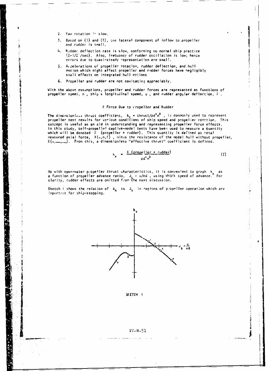
X Force Due to iropeller and Rudder
The dimrnsioni%:'s thrust coefficient, kt = thrust/PdYn2 , is com.monly used to representpropeller test results for various conditions of ship speed and propeller rotation. Thisconcept is useful as an aid in understanding and representing propeller force effects.In this study, self-propellel captive-model tests have beei used to measure a quantitywhich will be denoted X (propeller + rudder). This quantity is defined as tota!measured axial force, X(u,n,6) , minus the resistance of the model hull without propeller,X(u, ,. From this, a dimensionless "effective thrust" coefficient is defined.
k = X (propeller + rudder) (7)
Pd n
As with open-water p;opeller thrust uharacteristics, it is convenient to graph k, asa function of propeller advance ratio, J_ u/nd , using ship's speed of advance, Forclarity, rudder effects are omitted f.'om the next discussion.
Sketch I shows the relation of kx to JS in regions of p.op-Iler operat;on which areimport7,it for ship-stopping.
JI
g
SK ETCH I
IV-B-51
"" |. B1I

The path of kx during rapid propeller reversal is traced:
I. Initial equilibrium cordition (thrust - resistance)
2. Propeller speed reduced; blade sect icns approach zero angle ofattack (thrust zero)
3. Propeller speed further reduced; blade sectiois at negative anglesof attack (thrust negative)
4. Propeller speed further reduced; flow about blades completelyseparates (propeller dragging)
5. Propeller stopped and dragging ...
6. Propeller turning slowly astern but dragging
7. Astern propeller speed increased (blades recover from stalland begin thrusting astern)
8. Propeller speed approaches a constant value; ship speed graduallyreduLes; astern thrust determined by propeller characteristIcs
The representation of Sketch ! is not useful in the interval between 4 and 7. Mathemat-;cally, as n approaches zero, J. tends co infinity. Furthermore, beyond the bladestall-point at lirge negative angles of attack, k cannot be represented simply In termsof Js .For cargo ships and tankers the negative blade-angle stall wail occur at aJs value between 2 and 4. Another dimensionless coefficient is then convenient for
exp'cssing "effective propeller thrust." This is the coefficient cx = X/pdu 2 , used byBindel ý and others. The singularity in Js u/nd is avoided by using the reciprocal,nd/u
Cx
I/is u
.._nd
SKETCH II
The characteristic behavior of cx in a ship-stopping maneuver is shown in Sketch II(numbers correspond to those of Sketch I)., Because propeller speed will change much i•.1ii,•re quickly than ship speed, the behavior of X (propeller) is similar to that or cx'n Sketch 1i.
Because of slow propelle speeds in the region from 4 to 6, experimental evaluation ofcx is subject to serious scale effect (especially for the propeller operating behindthe ship)'; but if C, passes from 4 to 6 in a few seconds, the accuracy of the repre- isentation in this region is not crucial. An estimated propeller drag coefficient is
therefore used (see Appendix A). When unstalied propeller operation resumes (withreversed prcpeller speee), the k. vs. J. relation is again effective and simple to use.
The required segments of the kx, J5 curve are easily described by simple polynomialsin J . For example, in the region from I to 4 (of Sketch I), an adequate 'urve fitis obiained with k. = ao + aJs + aJ 5s . And since
IV-B3-5`

X (propeller) k pd4.
substitution of the polynomial in J for kx and -2 for J yieldsX (poe ner)
X (propeller) - (pd ao)n' + (pd3 a )un + (pa)u2 (8)
where a° , a , a• are determined for a particular propelier and hull.
In similar fashion, the k curvy segment passing from point 7 through point 8 may becurve fitted to J5 . For digital computation of maneuvers, the correct expression forkx can be automatically selected according to the Instantaneous value of JS J in accord-ance with rules based on Sketch I.
Rudder effect on X force is treated next. The draq of a rudder mounted aft of an ahead-turning propeller is a function of rudder angle, ship speed, and propeller speed. Ifkx is aoproximately parabolic .with rudder angle, 6 , a simple extension of the pro-peller-thrust representation to rudder drag may suffice.
X (rudder) a kx 6 0d na 6 (9)
Here we express kx, 6 a3 + a4 s , leading to
X (rudder) - [(pd4 a3 )na + (pd 3 aj)un] 6" (10)
When the propeller is dragging or reversed, the rudder drag is small and erratic. Noattempt is made to represent it.
Y Force Due to Propeller and Rudder
Representations of Y force and N moment due to propeller and rudder closely followthose for X force. The following will pertain to both Y and N
Because the flow past the rudder (of a single-screw ship) is determined by both shipspeed and propeller speed, the concept of kt vs. Js is useful for developing a polynomialrepresentation for side force in the propeller operating region from 1 to 4 of Sketch I.If in this region Y is a linear function of rudder angle, the symmetrical part ofY (propeller + rudder) with respect to 6 may be represented by
[(pd 4b )nr + (pdeb dun + (Pclbdual 6
A smalU unsymmetricpl side force is also observed for single-screw ships. This is called
the Hovga.rd effect" and is caused by asymmetry of propeller rotation. Several authors
attempt to explain this physically, but It is represented here as a simple function ofu and n , based on the results of straight-course experiments presented in the nextsection. Summing the symmetrical and unsymmetrical parts, the total expression is
Y (propeller + rudder) - [(pd'bo )n + (pd'b)un + (pd~b )u2 ] 0 + (pd'b;)r` + (pdab )uý
In the stalled region, for advance ratios much to the right of point 4, flow aft of thepropeller Is much disturbed. Rudder forces are then sharply reduced and difficult to
IV-B-53
:i.

evaluate. In this condition, it is estimated that rudder effectiveness is reduced toless than 1/3 of that in normal ahead operation. This is based on model tests of arelated single-screw hull with propeller removed.17
As propeller rotation is reversed, the propeller race ;s directed forward. Local flowpast the rudder is destroyed and steering control is lost. Side-force bias due topropeller rotation gains importance, and clone influences the directional behavior ofthe ship (in the absence of other external forces).*
N Moment Due to Propeller and Rudder
The representation of yaw moment produced by propeller and rudder, N (propeller + rudder),closely follows that for side force. An additional length dimension appears in theexponent of d . The number of terms in J. will depend upon the shape of the function
kN , and the precision required.
A summary of terms' used in the present study for N (propeller + rudder) appears below:
Operating Regionof Propeller Express ion for Rudder-Prooeller Yaw Moment
I to 4 N6n " (pd~cona + pd4 c un + pd ac u)6 + pdc 3 n (12)
4 to 6 Nn = pd %cu% (13)
6 to 8 Nn - pdc5 n ? (14)
TIME LAGS OF PROPELLER AND RUDDER RESPONSE
Engine Orders
Commands from the bridge to engine-control indicate desired magnitude and sense of pro-peller rotation."'-" A typical engine-order (bell) table for a merchant ship is shown:
Engine Order Propeller Speed (rpm)
Full Ahead 60
Half Ahead 40
Slow Ahead 20
Dead Slow Ahead 10
Stop 0
Slow Astern -15
Half Astern -30Full Astern -45
*'Although insufficient data are available to analyze ship dynamic stability In thiscondition, the reversed propeller may destabilize the ship by its effect on the flowabout the hull. While this could cause yaw divergence in either d&ref:ton, :- ow speedsthe unbalanced side force produced by the reversed propeller usually causes yaw angle todevelop in the positive (clockwise) sense. This tendency is shown In later computations.
The yaw effect is used to advantage by ship-handlers and explains their preference forport-side-to-pier landings,
Bridge control is not treated here, but may be introduced iivnedlatey. since there isno restriction to discrete prop~eller speeds in this analysis.
iV- - 5)54

The system used aboard naval ships is slightly different. In the naval system, theengine (propeller) is specified, followed by the desired sense and speed of rotation(in thirds). For this study a merchant ship is assumed.
Engine response to orders requiring large amounts of power is limited by the steam pres-sure available. Minimum allowed levels are established to protect the boiler againstexcess steam drain through the astern turbine. These limits guide throttle openinguntil desired propeller speed is approached.
Propeller Time Lag
Rate of change of propeller speed will depend upon -
1. Instantaneous propeller speed, n
2. Instantaneous ship speed, u
3. Previous steady propeller speed, ni , and nozzle combination
4. Propeller speed ordered, n*
A complete analysis of transient propeller speed would require propulsion-machinerycharacteristics and human-response factors beyond the scope of the present study. Asimplified function is used, which provides a good approximation for the purpo es ofthis work. It is based on full-scale ship data for the "crashback" maneuver. Propellerresponse is described by the first-order differential equation dn/dt + c n + c., 0Applying boundary conditions n - ni at t - t and n - n* as t - instantaneouspropeller speed is given by
n = ni + (n*- n1 ) (1 - 4tt/T) , t t - ti (15)
where T - time constant for particular ship and maneuver. This may be estimated byfitting Equation (15) to given response data.
Rudder Time Lag
The steering machinery of a large ship will provide approximately constant rudder rota-tion for rudder changes of more than a few degrees. According to U. S. Coast GuardMarine Engineering Regulations and American Bureau of Shipping Rules, average rudderrotation shall pt be less than about 2-1/3 degrees per second. In the S.S. GOPHERMARINER trials, the rudder was shifted from 35 degrees left to 35 degrees right in22 seconds, i.e., at an average rate of 3.2 degrees per second.
For constant rudder angular rate, rudder deflection is represented by 6 + 6(t-t 1 )and 6 > 6* according to sense of rotation, where
61 i initial deflection angle
t - time at execution
6 - ruddur angular rate
6 = ordered rudder angle
The sign of i is determined by the sign of (6* - 6w). Rudder-angle commands arespecified In degrees right or left of amidship (- or + , respectively), but radianmeasure Is used In equations.
IV-B-55

SUMMARY OF MOTION EQUATIONS
The equations of motion are summarized below in a form for solution:
X EQUATION
(m - 0o)0 = AIuU + (m + A2 )rv X(Hull)
A3 n2 + A4 un + A u2+ (A6rP+ A7Un)62 , Is > g,
A8 uU + Ague9 F g /Js > 92
A nX(Prop.+ Rudder)A10on A 11un 2 I/Js > g3
A1 2 nz +A 13 un + A14 u*" +A1 5u'I/n g3 2l I/Js
Y EQUATION
rB uv + (B2 - m)ur + B3 rv'/u + B4 rzv/u + Bsr;/u + B6 v3/u
(m - B)' = for % a r' rL , and u 2 uL Y(Hull)
1 BvU + B8vjvI + (B - m)ur
for p > or r' > r or u <u
(B 1 0 n2 + u +(B 12 n- + B13 un + BI 4 U-)6 , 1/Js>g1
+ B1 5u, E g1 l/Js> g2 Y(Prop.+ Rudder)1SlB16 n g 2 S1/J
N EQUATION
-Ic UV + C ur + C3 rv//u C r2V/+ rý'/u + C6 v'•/u
(Iz C) r = for b r 'L rL, and u u N(HulI)
C7 Vu + C8 vulvul/u? + c9rlrl
for r. > P r' r r' or u uL rL L
c 10nM2+ (C n2 + C12un + C1 3u:)! 6 /Js > gl
+ C 4U' ' I/J > g2 i;(Prop.+ Rudder)
C1 5ng I/Js int'ltnns (16)
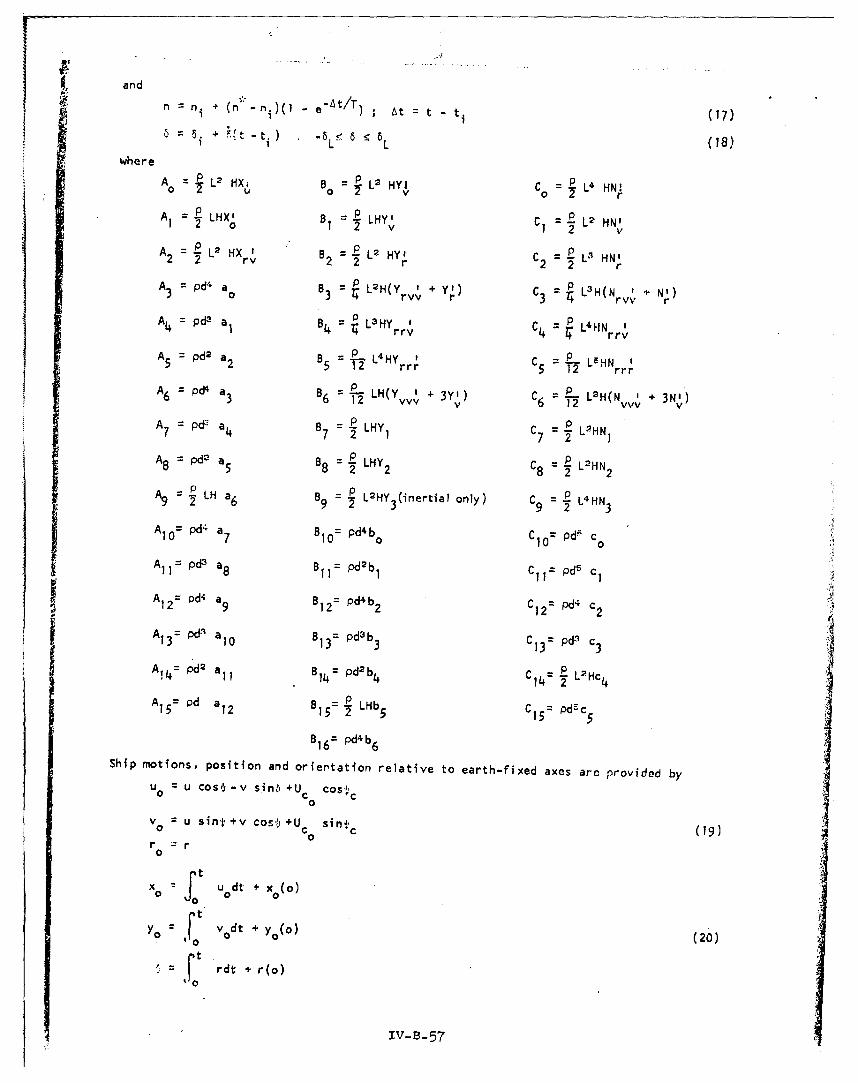
and
"n"n n e tnr) ; At = t - (17)- + .{t -t.) 6 6 (8I " L 1 L
where
= p L2 HX. B -- L2 HYI C - L4 HN'
A1 = p LHX' B = LHY I L2 HN'Ao 2 v 2, v
A2 = L2 HX " B 2 L2 HY' C 2 0L HNr2 2 rv B2 =2 r 2 2 r
A pd" a° B = p L2H(Y r +y) CH(N + N')3 o3 '4 rvv 4 Yr 3~ = r(vv r
A 4=pdP a,8= B L3 Hy I C = L'HN Irrv rrv
A pd2 a B = L4 HY try5 2 5 T I rrr C5 12 L-HN r
A =pd4 a B L-LH(A6 3 6 2 (Yvvv' + 3Y2) C p L2H(Nvv + 3N')
A d a B C -LHH= P F a 2 p H7 72 1 7 = I
A8 pd2 a 5 8 P LHY2 C8 = 2 LHN2
A 9 LH a6 B =.2L2HY (inertial only) C9 = - L4HN
2ny 6 9 .32 34HAIO= pd4 a 7 BIO= pd4b Ci 0 = Pd5 c,0
A 1 -da B pd2bPdll= Pd a8 11= 1 C1 1 = Pd5 c1
A Pd4 a B12 pd4b2 C1 pd4A12= Pd 9 B12= db2 C12= P 2 .
A13= aO B 13= pd3 b3 c13= pd3 c3
A!4= pd2 a11 B14= pd2b4 C14= R L2 Hc4
A1 5 pd a 12 B 5= LHb 5 C15 = pd5c
B16= pd4b 6
Ship motions, position and oriertation relative to earth-fixed axes are provided by
u= u cos,. -v sin-I +U4 cosUo C COS•0
v0 = u sint +v cos..+U sinm,' (9
r = r0
ft J dt + x (o)0
YO .0 vodt y y0 (o) (20)to
"* F rdt + r(o)0
IV-B- 57

EXPERIMENTAL PROGRAM
Experiments were made to evaluate coefficients of the motion equations. The program wasdivided Into three parts, according to the facilities used. Since the number and rangesof variables are extensive, test programs were limited to conditions necessary forapplication of the equations to particular maneuvers.
PROGRAM I: Straight-Course Experiment
A 14-foot captive model was towed at various speeds. Propeller speed was varied amongpositive and negative values, and rudder deflection was set at Intervals betwen plusand minus 30 degrees. A Series 60 model was used, particulars of which are given InTable I (see Appendix D).
The propeller was driven by a frequency-controlled synchronous motor, Integral with apropeller thrust and torque dynamometer. The pF-.er source and speed controller werelocated ashore and were connected electrically to the model through overhead cables viathe towing carriage.
Rudder deflections were set manually, by use of a tiller and protractor.
The three force components measured were the longitudinal cone.onent X (in II.re with themodel's longitudinal centerline) and the two lateral components YA and Yt (per-pendicular to the model's centerline, forward and aft). The net sA*e force ISY - YA + Y8 . The net yaw moment (acting about a vertical axis through the model CG)Is determined by N a YA x 9A + Y6 x Ct, where C is the longitudinal separationbetween the model center-of-mass and tte force-measuring balances (CA > 0 , CB < 0)
The force balances are of the differential transformer type, capable of measuring twoorttogonal force components and a moment component about a central agis. alance loca-tions and constraints are shown in Sketch III below. The model was constrained againstsurge, sway, and yaw motions but was permitted freedom to heave, pitch and roll.
SKETCH III
II A
1 ~DLWI.
SECTION 8-9 SECTION A-A
-I-
xv-a-53

Tests in this program were conducted on straight path (r' 0 O) with no drift angle(v - 0). Model speed, u , was varied between 0 and 5.7 feet per second. Propellerspeed was varied between plus and minus 7.65 revolutions per second. No data are reportedfor propeller speeds less then 4.4 rps, for reasons of scale effect on forces. Rudderangles were limited to 130 degrees, because of the effect of scale difference ;r thepoint at which rudder stall o,.;urs (near 30 degrees).
Turbulence stimulation (of flow about the hull) was aided by a 0.03-inch-diameter tripwire located 8.4 inches aft of the forward perpendicular. It is unlikely that turbulentflow was achieved at most of the hull speeds of this test. However, hLll resistance atlow speeds Is not significant compared with thrust forces. Furthermore, hull resistanceIs deducted from the total measured X-force in arriving at thrust coefficient infor.mationfor use in ship-motion computations; thus, the error Introduced is subsequently subtracted.
Hydrodynamic force and moment data are listed for various conditions of shlo speed, pro-peller speed, and rudder angle (u, n, 6), In Table Ii (see Appendix 0). These data aredimensional for the 14-foot-long model.
The data are reduced to coefficient form in Table III (Appendix 0). The dimensionlesscoefficients are defined in the section on propeller and rudder forces or the section onhull forces. Apparent slip ratio, S , is given by
pn-u0 pn
Coefficient data are plotted in Figures 2, 3 and 4, on the following pages.
PROGRAM I1: Large-Drift-Angle Experiwents
A 5-font captive model was towed at various drift atigles through a total range of 360 de-arets. A Series 60 model was used, particulars of which are given In Table I (Appendix D)To avoid wall effects, the tests were conducted in Davidson Laboratory Tank No. 2, withthe rotating arm at its longest practical radius. Side force and yaw moment were meas-ured through the entire range of drift angles. Since coupling effects of propeller andrudder should be smell relative to hull forces, they were neglected in the test. Thepropeller ad rudder were both fixed.
The model was attached to the rotating arm in a manner similar to that used in conven-tional rotating-arm tests of surface-ship models." The principal diference was thatthe flexure plate mounting on the model was made rotcttble in steps of •-• degrees. Thisextended the drift-angle capability of the balance beyond the usual ±30-degree limits,to any desired angle. The normal arrangement, with fixed mounting, const'-ins the modelagainst yaw, surge, sway, and roll motions, but permits freedom to pitch an,: heave. Themodification cheanes the nature of the roll and pitch constraints; but only .- neg-!gibletendency to pitch or rcll was detected at the low model speeds tested.
MWd•l speed was selected according to the drift angle of the run. For drift angle, near0 or 180 degrees, speeds of between 1.5 and .5 feet per second were used. At largedrift angles, the speed of 0.85 feet per second was used, to avoid unreatisticali• highFrogde n.mibers in ccinditions that would eiilst only at very low ship speeds. Speed effectat 90-dgree drift angle received special attention. The dimensionless side force"coefficient
yo Y
is plotted 3ainst speed for this condition, in Figure 5 (on a following pge).
IV- B-. 59
,_ _ _

SHIP-MOO(L: SlEAR S 60, Cb 0.60OA L/587.5 O44.O
L a 14D T
PROPELLER0: 4MLAKI d "lI IlL
screw e• r mo0e
04
Q3
01,09
*1
0*
.
a 066
05 104 0
"--020, 1o~ o i~ 4•... *Qj 0 C,
0I
1.4
- I -o 0 .. . .
0 .0 . .
FIGURE 2. VARIATION OF LONGITUDINAL FORCE COEFFICIENT k.,WITH RUDDER AN4GLE AND PROPELLER A.01VAtCE-RATIO
IN SKHIND-SNIP CONDITION

--,-0.5
Ue c
-s und I . ... .. . -~S- I ' i " a
-ZA) -1.5 -ID -0.5
• ~o Iu-30"
" ~~A 81.-I0-05
0 an -he
FIGURE 3. VARIATION OF LONGITUDINAL FORCE COEFFICIENT k., WITH RUDOER
ANGLE AND ADVANCE RATIO OF PROPELLER IN BEHIND-SHIPCONDITION. iiu/rnd (u* o, nco)
iv-B-61

Q4 pi0 8s+so
0.3+
0
asa
0.4 .4~0.
.
0-80
YAW-MO~g rt COEFFICIENT X~
FIG RE VAIA4O OF9 S0D.FRC AND YA1.2N O FCE T
4I
"8EHINDMEHT CONCIEiNT N
t dsriFIG RE .V RI TI N O S DE FO CE AND YA -OME T OE F1 IE TWITH RUD ER -A G! AND PRO ELLE AD AN~ j RAT O IBLEMIND-SHIPI COETOV -(

MODEL: $[RIES 00c '000 L .a&00LIS . ?.0 L/NU9U&S
0
NM-- 0
a -0 DEGREESrO.156
U, Ir0
U, FPS -
FIGURE 5. EFFECT OF MODEL SPEED ON SIDE-FORCE COEFFICIENT, Y'
IV-B-63

Measurements comprised X an4 Y components of hydrodynamic force and • componentof hydrodynamic moment. Dimensionless coefficleots N' , X' , and Y1 are formed, andplotted in Figures 6, 7,and 8, respectively (see irmediately followiri pages). Therotating-arm facility imposed a small path curvature In all tests of this program. Thiseffect was suppressed by averagiNg data taken at positive and negative drift angles.Averaged data are represented In the figures. In view of the symmetry of the averageddata, drift-angle arguments in the figures are shown only from 0 to 18C degress. Ideally,the drift-angle experiment would be conducted on straight course at many combinations ofpath curvature and drift angle.
PROGRAM III: Pure-Yaw-Rotation Experiment
A 5-foot model was torqued In pure yaw rotation by applying a known yaw moment via fall-Ing weights and pulleys. The resulting steady yaw rate was measured. A Series 60 modelwas used, particulars of which are given in Table I (Appendix D).
A vertical mast was erected In the model, coincident with the model's negative z-axis(th,'ough the CG). The mast was a drum having two fine cords attached, which, when woundaround the eruim, applIed a pure yaw moment. The cords were led over ball-bearIng pu.lleysattached to the outer sides of the walls of Tank No. 3. Weight holders were hung fromthe cords, and the system was arranged to permit the weights to hang freely and traveldownward as the model commenced to rotate.
In testing, the lines were wound about the drum, elevating the weights. When the modelhad been pos~tioned directly between the pulleys, it was released. After an accelerationinterval, the time of one-half revolution in yaw was measured. Different weights per-mitted a determination of the effect of yaw rate on the dimensionless moment coefficient,
N
SL4Hr8
Results are plotted in Figure 9. These show negligible change of coefficient value overthe r range of the test.
COMPUTATION OF SIMPLE DOCKING MANEUVER
The equations of ship motion (16 through 23) wore programmeo for numerical integration
by digital co:nputer. The computer source program, written in Kingston Fortran language,is listed in Appendix B. The program applies to calculation of various turning, stopping,and accelerating maneuvers of a single-screw ship.
A representative application of the mathematical model is presented, in the calculation of asimple docking maneuver; namely, the "one be1!" landing. This maneuver involves a single iengine reversal for halting a ship alongside its berth. The particular purpose is todemonstrate sensitivity of sh'p response to operating and design parameters. Conditionsof the maneuver are idealized in the sense that no tugboat or MPD forces are applied, nowind acts, and deep-water hydrodynamic coefficients are used. The one-bell landing is alegend for larqe ships, but as a limit maneuver it provides insight into the dockingproblem.
Characteristics of the study ship are given in Table I (Appendix D). Hull dimensionsapproximate the MARINER's, but are based on a Series 60 form. Coefficient values areiisted in Table IV and values of other parameters in Table V (Appendix D). ConventionalY and N hydrodynamic derivatives are obtained from Reference 13 (Model 60),
To extend the results of computations to ships of other sizes, the following scaling lawsmay be used: Subscript A refers to the study ship, and B to a geometrically similarship of different size. The factor X is tie scale ratio based on length; i.e.,
L B/ .A Typical examples of scaling are shown below.
IV-B-64

OJO
MDODELS•0 G 0iS O
006 L/ lSO L/N O6.?75
* 31UD100 ANGLE a*
40PROPELLER AND BILGE KXELS REMOVED
I O
004
-004MODEL TESTED ON NOTATING ARM AT 53 FT.
(LARGE ST) RADIUSPLOTTED POINTS ARE AV'RAGES OP DATA
-ON AT POSITIVE AND NEGATIVE DRIPT ANGLESMODEL SPEED
156 •00 1iw: Uv o.66 FT/SEC
-•mI1041014 so}:IU425 PT/SEC
WATER [ 9PTH: D*4.,OT.W•b/aI.O
-0.10o 60 0 ____ ____ ____I I,300~o 9 0 00 1206 150o 1800
FIGURE 6. YAW MOMENT COEFFICIENT VERSUS DRIFT ANGLE(MOMENT AXIS THIROUGH MODEL C.G.- O.015L AFT OF )
Iv-B-65

00 0
IIANII/
xI
IV-B-6

LL
I- -
z
v_ _ *L
o ,B-6-

OsgusoI UU
SERIES 60
o K.O$ 0O10
r, ftAD/SEC----,
FIGURE 9. EFFECT OF MODEL ROTARY SPEED ON YAW MOMENTCOEFFICIENT, N/p/2 LWHr'I -
IV 3-C
a.

Distance: xB - XA x 4 Linear acceleration: uB " UA x I
Angle: 'B - VA x I Angular acceleration: r " .rA x A'
Time: tb - tA x A42 Speed(ship and current) u1 - uA x A
Force: X8 , XA x AL' Angular speed: n a n x A-i/a
Moment: N a N x 4
B A
The correlation of hydrodynamic terms between models of different size (and especiallybetween model and ship) is a major problem in ship hydrodynamics. For this reason a14-foot-long model was used to measure forces depending on rudder actions, and frictionscale effect was accounted for in scaling thrust forces. Still, the main interest ofthe work Is to extend ship-motion analysis to permit evaluation of parameters affectingmaneuvering performance at low speeds, and not the precise determination of ship response.
The basic conditions of the sample maneuver are these: The ship approaches a pier at aconstant velocity of 4.3 knots, relative to the water. This corresponds to a propellerspeed of 20 rpm. Turning rate and drift angle afe initially zero. The "full astern"command Is executed, and subsequent ship motions and trajectory are computed.
The calculation is repeated for several variations of each of the following parameters:
I. Maximum reversed propeller speed, n*
2. Propeller-response time lag, i.e., time constant T
3. Velocity of uniform water current, Vco
With propeller reversed at low sh~p speed, rudder deflection was found to have negligibleeffect on ship notion and trajectory; hence, it is not included as a parameter in thesecomputations.
The distance and time required t.o stop are used as performance criteria for studying
sensitivity to parameters I and 2. For parameter 3, the lateral trajectory character-istics, position and velocity, are used.The computation proceeds from to , when the comnand n* to propeller is given. Formally,the initial conditions of motion are u - u(O) , vwr-u- ,,O. Initial heading, #(0) ,
is arbitrary unless water current is specified. Coordinates x (0) and Yo(0) are alsoarbitrary. Typical computer output is shown in Appendix C. 0
Results
The effects of malximum reverse propeller speed are shown in Figure 10, following. Clearly,variations of ny' about the base value of -45 rpm cause significant variations in head-reach and time-to-stop. For the study ship, -4A rpm coriesponds to normel "full astern."This is the command most likely to be used for killing headway of a fully loaded vessel.The response to emergency full-astern (taken as -60 rpm) Is significantlv quicker, andresponses to lower values such as half-astern (-30 rpm) are unacceptably sluggish fordocking. The curves representing time- and distance-to-stop are similar in characterunder these conditions. This Is In accord with the simplified relations between comstantretarding force. X , and the time and distance necessary to destroy kinetic energy.Energy and -nation equations yield
(•- x .)0 and t -x)2A X
At low ship speeds, X is uinly detervined by n a hence, both s and t areproportional to ',In a
IV-i3-6Q
I

ILI
ii
LL_
mlm
a0 -- 0
0 0
II-
oII , ,
-30 - 5 -0 -ton4, ANA
FIGUREIOY EFFECT OF REVERSED PROPELLER- SPEED ON DISTANCEAND TIME REQUJRED TO STOP SHIP FROM 4.3 KNOTS
lCOMPUTATION owsIIIPL9 oocKlme mANCUVIEl)
7 1"

Figure 1i on the following p)age Indicates how the response time of the engine affects*1distance- and time-to-stop. Since the time constant T is a measure of delay in
achiev~ng n* , it dictites delay in reaching peak deci.lerat ion. This affects distance•ove~ed 'n each succeeding increment of time after t0 . Time-to-stop it no• correspontd-ingly affected, ho,.vver.
The validity of the iongitudinal s~iip-m~otion calculation was teated b.' r~ornnuting stoppir•.;amneuvers of the E~SS SUEZ and comlparing reslt.ls wilth full-scale tes•. sat •e,3•rte• byHewins, Chase, ano Ruiz.x'
Ship trajectories correspon•ing to three variations of the basic docking maneuver arepictured in Figure 12. Water current is the pasrameter. A tini, history of significantcomputational variables for the no-current condition is shown in Figure 13. Computedyaw-angle and drift-angle values develop significantly prior to ship stopping. Measure-isents of free maneuvering are unlavailable for verification of these results, but tend-encies appear to be correct in the light of experience with full-scale ships. Thegeneral preference of ship-handlers for port-side-to-pier landings is based on theseeffects (for right-hand single-screw ships).
Trial computations were carried out, to examine the importance of steedy-state hydro-dynamic terms in low-speed transient maneuvers. These computations showed that elimina-tion of all steady-state hull ter-ms did not apprecilably affect the longitudinal nut gonresults shown in Figure 13. However, effects on, lateral notions were quite large, roughlydoubling the values of yaw angle, drift angie, and lateral displacement. in anothertrial, only linear hull hydrodynamic terms were included. Results nuore in line with thebasic compu~at ion were then obtained. However, it is cautioned that the simple dockingmaneuver does not involve large drift angle or space turning rate through nost of theduration, as might be the case in other low-speed msneuvers.
The effect or uniform wamt~ current on a slowly noving ship is important. In Figure 12the effect of a one-knot current, setting east, is compared with that of a one-knotcurrent s•.ring west (relative to a north-south pier). The right-hand ship is setheavily westward and put hard against the pier. The left-hand ship is set eastward, anda portside-to-pier landing is impossible. Therefore a starboard-side landing is shown.Slecause uniform water current adds a constant velocity to other ship not ions, tine-to-stOp is very important in water-current cases.
A limiting criterion for docking is contact velocity with the pier. Lateral contactvelocities of -2.3 feet per second* (for the ship set westward in Figure 12) or 1.1I feetper second (for the ship set eastward) could result in costly side-shell da'age. Arealistic nonl-uniform current would be weaker near the pier, and nu't-re confused, but the
iI desirability of having additional lateral control forces available is apparent.
Dimensi;onless turning rate, r' , is included in Figure i3. The r' variable correspondsto L/Rt in steady ship turning (with Rt the instantan~eous turning radius); but thisinterpretation is lost in transie'nt 'maneuvering. For examplie, in Figure lZ it is shownthat ship trajiectory mely curve to the left a• the ship yaws to the right. Oimensionlessturning rate is, therefore, not suitable for discussing trajectory in transient maneuvers.in "his study, r' is used only as a criterion of dock ng-type ma•neuvers.
is
S , ~The conclusion's of this study are based on experimenmtal results, results of computed• : maneuvers, and mathem-atical rumdel develop-ent.
Conclusions Rased on Experi--onts
S;I. $traiq;hi-course experiments show that the' speed of an ahe~d-tu~rning propel'er Strongly
,nftl.ences the rudder effectiveness of a single-•.rew sn~ip. The relation 'may be
'*CObined with yaw rotation, the lateral velocity at the stern (at station !S, on 70
Stations) is -2.7 #et per second.
IV-B- 71
__ ____________ ___ _____

-3 400
4-4
4ii
ogo10 t 30 0 soso
TIMECOMSANT , SEOND
wmt~ fv(n~ln i)(1-- 1 T
FIUEII FETO NIE-RSOS A NDSAC NTIERQIEzOSO HPFO . NT
(CMPTA0O OFSMLEDCKN AIVR

"in win sieul vsxuuw JOIA
V! -v! - -8
+ II
I..
9 U
C0
aw
C£ 0Uw
.12
C- Z
Sir_ _ po
x ]0*R Tpilsw04 ivw331fe

60,000
1 000- '0 S 00
0.4 - 40,00 O
300OoSoo 5 * N
10,000 z0
0 L 0 L 0; "1 01 0.
•J m,.*m~m ---,* 0,00 t
,h"00
"XTHRUIT 0 -"i
4 i - O00
o ~~ -0 -- 0,000-
al _0 -- '0,000
000
14 A14 700
hI 12 -- 1O0
£ S 1.0 10- I - 0 hi
oe r 0- IIt
SO, ; O sI to 1 1.
,- 40
* 4 \ Ox I-GO 120 I0 240
TIME, SECOkOS -
-4
-0o
F'GURE 13. COMPUTED TIME-HISTORY OF PRINCIPAL VARIABLES IN TYPICAL.
DOCKING MANEUVER L

expressed in terms of the propeller advance ratio Js for ahead ship rntions. Whenpropeller rotation is reversed, rudder forces are small, erratic, and irn.ffectivefor control.
2. A significant side force is generated by the rotation of a single propeller behinda ship, especially for reversed propeller rotation at low ship speeds. This forceis responsible for a tendency toward positive (clockwise) yaw rotation during ship-stopping. The ratio of measured yaw moment to side force locates the center ofeffort at approximately 10%L forward of the rudder post, for reverse propellerrotation, and approximately at the position of the rudder for ahead propeller rota-tion.
3. Hydrodynamic yaw moment resulting from pure yaw rotation is closely proportionalto the square of yaw rate for a 5-foot Series 60 model at yaw rates between 0.04and 0.07 sec",
Conclusions Based on Computed Maneuvers
1. Computations show the importance of maximum reverse propeller speed, n , in ship-stopping from low speeds. Since hull resistance is minor at low speeds, the stop-ping force Is mainly determined by n* squared.
2. The time response of the engine Importantly affects the speed with which asternthrust, hence ship deceleration, is established. Since this affects the timeduration of the high-speed part of the maneuver, it has much greater effect ondistance than on total time required to stop.
3. For some maneuvers, time-to-stop is more Important than distance. For example,ship translation due to a uniform water current depends directly on total elapsedtime, and not at all on distance traveled through the water. Therefore, a maneuverwhich may be simple for an unassisted ship in still water could be impossible Ina modest current, depending on the time it takes to complete.
Conclusions Based on Development of Mathematical Model
1. Propeller forces are conveniently represented in motion equations by following thefamiliar k vs J notation. Extension of the kt , J5 concept assists In therepresentation of longitudinal force, lateral force, and yaw moment, as convenientfunctions of ship speed, propeller rotation, and rudder angle. Applied to bothahead and reverse propeller rotation, the technique provides Insight Into thechiiging propeller flow conditions. After blade stall, a locked propeller dragfunction may suffice until stall recovery. Computations may be organized on thebasis of Instantaneous J. value.
2. If the water current can be assumed uniform, vector addition of ship motion throughthe water and motion of the water current permits a considerable simplification ofthe equations of motion. On the other hand, if water current is so irregular asto disallow this assumption, mathematical representation may be impractical.
3. In general, the variety of ship motions possible at low ship speed is boundless.Because of this, appropriate force and moment data are necessary In computationsof low-speed ship maneuvers. Steady-state hydrodynamic reactions are complexfunctions which cannot be arbitrarily excluded from ship-motion equations, even atlow ship speeds.
It Is recommended that future experiments be designed to investigate a complete range ofcombinations of drift angle and space turning rate. Effects of shallow water should alsobe determined.
The mathematical model is a useful tool which may be extended to Include additionalforces, such as wind and auxiliary maneuvering devices. Constraints due to anchor ormooring lines may be added. With the proper data on external forces, the mathematicalmodel provides an excellent means for analyzing many complex problems associated withlow-speed ship maneuvers.
IV-B-75

ADPPIOIX A
DRAG OF LOCKED PROPELLER
In tre cýerating region between 4 and 6 of Sketch I (see section on 11 Force Due toPropeller and Rudder"), the propeller force Is essentially a drag force assoclateui withpropeiler blades cont;nuously changing orientation and angle of attack with respect tolocal flow. In the absence of detailed experimental data, a simple drag coefficient fora iocked propeller can suffice. This may Ie estimated on the basis of developed bladeari-, DMR, ship speed, u , and mean wake fraction in way of the propeller, w
X (propeller)dragging - C0 2 A u
.C 2 x DAR x [u(,-
ti . p d 'a • L .
where
as a C0 x DAR x x (I - w)l
Estlmatons of CD for ship propellers are discussed In Reference 19.
I.
DB
117-3-7

APPENDIX
¶ COMPUTER PROGRAM FOR SIMPLE ENGIt4E-AND-RUDDER M1ILUV~tx5
C KINGSTON FOPT1PAN 2. 1620t STEVENSI
I PF~AD l00.1ICC l.JloJw.*1.7).l112)PUNCH 100
PUNCH 101 .11CC .J)*JxI.7)slw1.I2)PUP.4CH 102C0NLlI C(1* 31*CC I.4)*C( 1.51/2o0CCNL.!.CONL-1*CI 1.4)
C0NLl=CONt.24C( I.4)C0NL4.CONt-l3CI 1.4)COWL5*~C0NL4fC (1.4)
CONnI'C( I .)vC( 1.6)CN0NI22CON0l*Cl1.6)COND)3aCoNO2oCI 16)
LON04-CONOJ*CI19 61CON'-5xCON04*C( 1.6)
AlwCONL)'CII.e2)A2mCI I* 1)+C0NLZ.*C13s3)A JeCOND44 C(13 4lA4aU:OND.J*C 3.5)A'%mC0Nn2acC 3.6)A68COND4*C (3,7)A7uCONrO3* C( 14A~uCONP)2*C(4*Z)
A9vCOWLl) C (4.3)
AIO.CONU4*C(4%4)All sCONf)J*CiC *5)A C2sCOND2*CtC4.6)
A13sCONC~l CU .7)Ml 4-COND4*C (9.6)A C5mCOND3C)J(9.7)L00.C(j.1)I -CONL2*Cf5. I)
HR :CONL2*Ce3.3)-C( I 1E43 CONt 2*C('i*4)tA4zC0NL.3*Cl 5.51HC5*C0NLvClC5.6)06-CONL44C 5*,7)t17-C0NLl* C(16q1)C08xCONL I C46.2))PP)C0NL2*C(6.3)-C( I * )H10-=CONC)4*C(694)
)11112COND2* C (6,6)
CA) 12-rON04 *C ( 6 * 7)
tlC4-C0NP)2*CC7. I1115=CONLIK4C7.2)(C l6-CONO4*C(7i3)C~wC(1q2,-CONL4*C 17.4)C1:C0NL2*CA7%5)C~uCONL3*CI 7.6)C3zC.)NL3*C(7*7)C4&C0NL4*CCS. I)C~isCONLZ*C(892)
C6mCONL5*C(8*3)
C7mCONL2tCf8*4)

L9.CONI,411C (kl6 I
LCII (,')No'; C 9 I)C I P (ONI)4 C (9 9 P
C I 3=rflNfl'C (9% 3C It4: CNLP NC 41)*~ 4 P
f NMPr)=yMP4laC( 12t2)*C( 1.4)
UGC10.1)
V:rC( 1('2)
VG L ( O0,2I
PPSD .C. 1 0.05)
L):LC(10*3)
Dt 0,C(?, ;7)
PS I C (1 .4)
7 w=.S0PTF tU4U+V;V)
RPfPI=P*CI I.4)/W
SIiFTA=AtSF I 4t. TAI
IF (SPPPI-C(2*2)) 90.50.51
50 IF (,SPETA-C(2i3)) !i2?.52951
52 IF (U-C(2.4) I) 13993 YHUI.L =A I*U*W+A2*PNVIYHULL=fH **+'**~4**V*/~A***24U+5V*/+6R4
FNHUL=C1*UIV4C2flUIP4C3*R*V**2/U4C44V*P**2/U4C5*V*03/U+C6*P*3/UrO TO 3
51 XHULL =AlIU*W4A2*P*VYIJLL~t7*V*W4MU*V*AI3SF(V)+&i9*U*PE.NHUL~rC7*U*V+C84V*U*AI3GF(V*U)/W**2+C9*R*A6SF(R)
3 PJ=PPSIC( " 6)/1-IF (P.J-.276l 60960461
60O IF (QJ+.I5(3) 63.63962
63 IF (P-+I.fl) 65.65.6461 XCONN=A3iPPS*2+A4*UIP05+A5*VU2,(A6RPPS*2+A7*U*IPS)DEL*92
YCONNdtiI0MRPSI*2+MII*U**2+(BI2*PPS**i -8I3*U*RPS+t3I,*U**2)*DEL
ENCON=CIO*W~PS**2+(CII*PPSI*Z+CI2*U*R~j+C13*U**Z)*0ELt GO TO 462 XCONN.=A(I*IAW+A9*U**2*DEL
4*2.
YC0NN=( I ý*U**2i OEL
GO TO~N0~ 4UU~*E
64 XCONN=AI4*PPS**2+AI5'IJ'PPS
YCONN=I3I6*PPS**2fNCON=CIr,4PPS*02
65 XCONN-AIC4PPS**2+AI I*uNPPSAIZUU.*2+AI:SIU**3/RPS
IV-B-78

'4 00T- i v~H1.LL+XCONN+C.1Z.5fl/AO
V0071 (Y4iLJLL+YCONN+YMP0)/(4O
RO(OT (F NtiIL +LNrCON+ENMPI))/ CO
1Ut- A v'i7.Z Ii 1TA
rT=T*O. IJTvST
J T aJT * 10JTsJT* IIF( IJT/JI-I 1 6.5.6
5 PUNCH lUS3,T.P0I.U.X.YotdlOA.RPRIRP~bDLU.XC.ONN.XHULL9Ui)oT.UGSVG966 1J=U4uDOT*C1Z- II
V=V4VOT'C(2. I
R=I'PSI4R'C(2, I
UG-C(11,6)4COSFC(il,7))+U*COSFIPSI)VVSIN;-PSlIVG,.C(1I,6)*SINF(CtiI.7)I4V*COSF(PSI)+U)SINF(PSIIXaX+UG*C(2. I
IF(U-C( .61 71,70.7070 1 F (AEASV(DE L -AE45F (DELL) 1 4 0 41 4 1ii40 OFL = tL [ML*( I *I ) *C,(2. 1I
GO TO 2
IOU FORMAT (1I-1
I / ( 7V- I r. *4 )
101 FOPMATI l2(7CIO.-3/1 I102 FORMAT 142H T PSI U x Y BETA /66H1 PPRIME
I PPS DELTA THPUST RESIST. UnOT UL VESI
10.3 F'UIMAT (F5.O.F7.I.o'7.2,2F.IF7.2/lHI.2F7.J9F6.IFIO.O9F9.O93F7?9v
7 1 (P0 TO ILNO
NOTE: Projrani allows inclijsion of additional constant Control forces inlateral and longitudinal directions, YMPO, NMPO, and XEX. Thesewere made zero in the present study.
IV-B3-7 -

00 t 00"J-4 N
It'8 0000"0 000o-reO 00 0 --00000000006000000.0.00N0
cci~ 400 80 0fiN a0 M V)
F, 4 04 A9f;0,ft oN.
In I
m fri
Noo~ooliti 1. 1 iiiiii 1M 11,11i , i10
U .-ým oo 4l0O00000009 0000.00001000000
u 00!20000-oo b- 0 0 0 0
0 u0za000000000 mo
C16 WWhWWWW.JWWWW .
at 0 0 0900 q9 00 0 0 1- PP 1* 1 1 P 1 PP 1*P 1*CC 1111n 90- N ~ 0ýNR0 8 .
). V I-4 P *m mr-PPC
S. 0 o 00000-00000 f0f f-Nl f 99N00000.00000 If00 Nt-4 -01
P~~i ' + 1 + 4 w + +4 + * + 6 0 f 9 0 4 4 4 P P P P
It CY UW~u~.W 0. .* .'o (P 0 * 0-T 000; 9 100 T .il til lilt 08111
-ccfi [1 0 ,n# 9
m 0 00 O 0N ON0i -01 il.P0PE
000009900000 Nnomlow n
0~ 400-90fN~fP 0 9N0CN 0000000000 --- el0ft~ff
w w , W IL 1 11 W+
oM 0 0 r 0 g, Q0 .t 100 N1 i a o1 e ' 1 n DOPP 0r 1 nIIgolfa
L+ I,
in I Q4 0 N 0 - 00 N 0 . 0
o . .- . ). 0 .- -00 0 0330 049 00 0004NP~IflQ
+ # I +4 I * + .+ + +-0 N 90 - Q9 0
I t I I - C 0 0 0 -M 4 0 C 0 4 0 01 4 1CN
1+4f P-4 fry,

APPENDIX 0
TABLE I MODEL AND SHIP CHARACTERISTICS
HUJLL 14-FT MODEL 5-FT MODEL SHIP
Length, BP. L , ft 14.00 5.00 528.5
Breadth, B , ft 1.868 0.714 75,5 jDraft, H , ft 0.747 0.267 28.2
Block Coefficient, Cb 0.60 0.60 0.60
L/B 7.50 7.0 7.0
L/H 18.75 18.75 18.75
Displaceent, A 731 lb F.W. 35.6 1b F.W. 19,300 L.T.L x H . sq it 10.46 1.335 14,.ýJ
Lateral Area of Hull, sq ft 10.35 1.320 14,750
Mass of Model, M , slugs 22.75 1.11 1,345,000
LCG/L from FP 0.515 0.515 0.515
Radius of Gyration in Air, ft 132.1
RUDDER
Area of Rudder, AR, sq 't 0.167 0.021 238
AR/LH 0.016 0.016 0.016Aspect Ratio of Rudder 1.90 1.90 1.90PROPELLER
Troost - 4 blades
Diameter, d , ft 0.518 0.198 19.54
Pitch, p , ft 0.599 0.187 22.50p/d 1.15 0.95 1.15
Mean Width Ratio, MWR 0.261 - 0.261
Expanded Area Ratio, EAR 0.550 - 0.550
SBlade Thickness FractionBtf 0.045 - 0.045
SRake, deg 6 - 6
IJ
III I
i
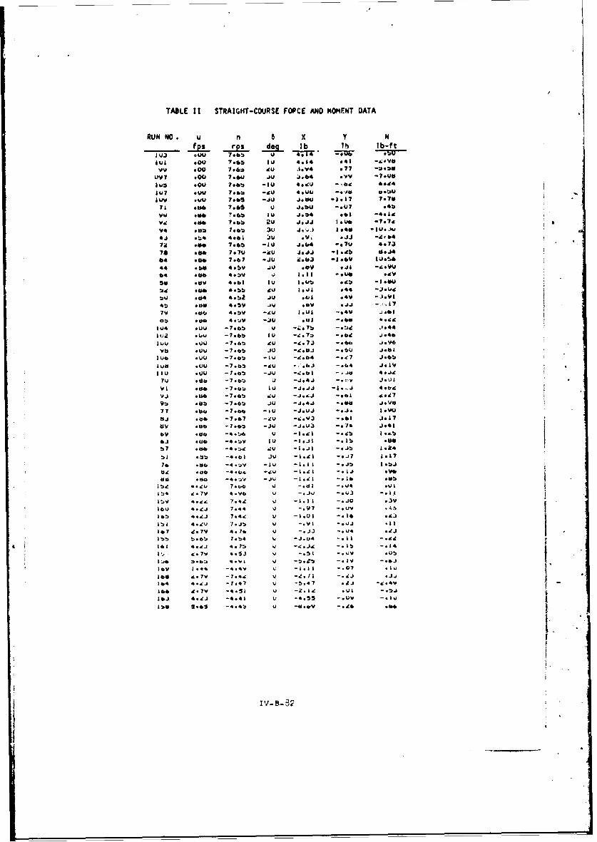
TABLE II STRAIGKT-COURSE FOPCE AND MOME~NT DATA
RUN NO. u n 6 x y N
_fpsa rps dog lb lh lb-ft
lul .00 7-6 IV. 4.14 .*1 -..Vb
Vv .00 796* du J.*.4 .77 -4.Oil? .00 7.64J ju J.64 .VV -7.0W
tub .00 7.bb -£0 40ev -09 1.14.7 .4W1 7.bu *cU 4.04.1 -. 0" Do
Ivy 7.4105 -.,U £.*u4 -1917 7.140
7* .e 7.05 Jew4 -. 07 .*b.uM0 ?.6" IV J.ý41 .61 -4*14
ilL @oe To..) 2u J.s.aJ 1.04 -7.7d
.e 7.6b -£0 J#&64 -.7u 4.73
74 .86 7.79 -icu J.JJ -1.95 *b
104 .Me 7.07 -JU id.40 -1.06 £.6
44 .6d 4.5v ;u 1.09 .44 Jd.IJ
79 .30 4.Wd -Q 1.451 -quo .9V0
so .0v 4eb IVO I.aa -. 44 -.
.06 -7.06 IU *-.j.7 04 -J*4
IOb *UU -7.5v u -. 0v -. jj .I
.00. -7.10V .40 -. 0 -. 60 **,99
31)0 *42 -7.65 V* 7b.6 -tL .. 0jug *U -7.6b -IV -. g 7:0. -. 694 J.46
LAO VQU -7.46b -JO -.. bl? -ebbJ3Y
70 .Mu -7.6b 0u -.9.4.1 -06 Joel.4
VIv .0V -79.. U -J.bj -l.64 J9.1 .Mu -7.bb .JU J.:.b *..0m L.L
96 .30 -7.6!3 VO -.1.4. -. 3 .1.
0.1 .4.4 -7.07 -IV -j.V3 -. 3 .1
vi9 .4. -7.6b -JW -J.1.0 -. 71 4..97e9 bb -1..6t JU -l.LI -004 Jove
bi- U.L. -1.67 0Ad -5..v3 .1.1 L.
6v4 e.7' -4.t51 u -1.,1L .41 -. 6.116J U6L *.t£ IV -4.I J UI -. It,
£b4 5.41 -4.46 0U -1.4V -. J7 .40"
76 .*& -4-ýv IV- B-11 i~
U1 , I

7'TABLE III STRAIGHT-COURSE DATA IN COEFFICIENT FORM
RUN NO. JS K x K y K N s Y NI
____ 0_ Y ~ NW 0 b -7 Ou
VV4 .00 .bU8 .0* .*0j .IAJO
V7 .04W .4*J .lI' -I.?o I.UUfjlub .00 Z1*4, -. 08l 3.0* 3.000
IUV .04. *466 -..14 IO;4 i.000it0 # d.0. .046e -. 34 oil~ b Id000 1 .
Vu Odd .447 .07 -0.00 .a 1 9 U -.04
9d a"g *44di .14 -1.b4 -did .14 -. V7
94 -91 *Jolb .10 -4.44 Ouluj .,9V ,1
4.1 Od4 .*Ji oil -1.7J .004 .1* -tub
70 kef .410 -0 1 .1 u.6*4 b -037 .0804 Odd O4bV -Odl ds.V Ott I -. 2j 4. 144 .dV *ja54 all -I.VI .Ths .07 -.U4614 *44, *4*4. -. 04 .IV tW7 -. 01 v0jU4 .37 .494 .08 -1.38 .4.71 .0j -. Us:
zd .46 .489 I* u d.104 .6410 .0 -.04
45 J . d& .7d oil -d.09 .80i: .04 -.0j7V .46 *jag -o17 dc.,a .4,07 -OUT .04
#5 .46 .Ji4 -. ,d 'g.7 *4,417A -.09 *Uf
*04 .1.4. -. 4.s7 .. 04 .0d 3.000idd .0U -.447 -. Uu Ud 3.000104 .UOu -O44b -. 08 .94 1 VVUve .Uu -. 347 -.07 .V0 * .00
I" .VV -. 4cb -. U4 .ts7 3.041Iva .00 -. c -evil . 71b 1.000
1*0 .0u -. Jc0 -4W; I.0 3.000V
7U -dd -. O84 -. 0V .71 3.3041 tb -.08 LJ~91 -. 44 -. V08 -.0 I I.7 1. IOU -.0. It, #UV* -Oda -.iVj -. UT 1.3bIl 1.1du -.*0 V.9V5 -eel -.408 .011 V4 I.3db -. Id V04
77 -wd. -.4b8 -.04 .4b 3.107 -. us Ud~
83 -. &A -. j44 -.07 .7!) 3.1u7 -.08 .4.48J9 -. ki -. Jbd -. 09 b31 3.3031 I - U3J
69 -.Jo -.480 -. 09 bj1 3.41b -.04 .ut
64 -. j6 -. 4*0 .0U5 .58 1.314 -.ua .01
bi -.47 -. are -OIJ .76 3*434, -. Ut .01
7b -. 40 -.J41 -Old 1.00 3.414 -.Wti .0*V ~-.J6 -.037*1 -. U4 .6,9 3.433 U.0 *01
-J6.44 -. j7& -. 06 0 bo I 3..41 4 .0 1 0
154 1.U0 .104 .vu .U0 wb .00) .0
154 '*W .gOV -.0* -. 046 Ube .0 .00
15V I.30 .3540 -. 04 IV0 Usu0 VU0 .
*4,0 1. 10 1'76 -.0 .1a L'uV, vuJi
365 1.30 .171 -. Od .06 V04m .Q .00
1 *7 1.34 .444 -.0I .34 UZI. *0 .00 U
*55 1.45 .087 -.01 -sob - t, .0 .04
163 ,70: .wu -. 05 -. 4v -. 4414 .0 .jV
lb j 3.1 .1 80IU -.04 w04 -.0a 0w. V.0
1!06 dO -. 34i -.0* -. 46 -. yfw VV0 .oV
1V -. "L -. 4U . -. b0 .&4 .0 4 1 *t40.UV 0
164 -1 V -. 4u9 UOj -.6d7 vtp5 . W U.0160 -1.71V -. gvv -.04 j6 C.UJ4 .0 .00w
j ~IV.B-33

TABLE iV
COEFFICIENT VALUES FOR SMIP IN SIMULATED MANEUVERS
X1 -. 0068 Y3 - .0062
XI -. 0075 b - .010o 0
x , .168 b. - .0326
.4.941 b, .294
*, -. 231 b2 .397
as -. 043 b4 .12
a-.141 b5 .0127
a4 -. 322 b6 -. 080
-. 059 N- .0107
- N' -.0095v ! -
a .300 N" .070
as• .600 i/2(N~v + N;) -1 .43
~~(rvvN*'
49 ,'.325 1/2 Nr I - .127
410 . cO0 'A .3051/ 1.50 1/6 Nc.v+ 3W - .061aa1.00 N, - .095
Yv1 -. 168 N, - .169
Yl -. 305 N3 - .525
y; .089 0 .15
'/2(qr~v•+ Yr) -. 614 cl -3.85
1/2 Yrr -1.15 ca -4.4,1
'A6 vrr, -3.20 r- -2.62
Y•-.305 €o .79o= - .6s
TASLE V
jFIXEO PARANETERS lH EXAMPLE COMPJTATIONS
P .262 (15
.
L
.376
9. "- .158
, v-1.00
4t 1. e~wto ie

NOMENCLATURE
The basic nomenclature follows tha of SNAME Technical and Research Bulletin No. 1-5.Principal exceptions are the cholca of tyn'cal dimensions used in forming dimensionlessquantities, and the use of additicnal notation.
Three different right-handed, rectangular coordinate frames are used:
I. (x, y, z) are body axes with origin at the center of gravity, x d'rected towardthe bow along the longitudinal centerline hull axis, y directed toward starboard,and z from deck to keel. The x,y plane is horizontal with the ship In staticequilibrium.
2. (xo. Yo. zO) are fixed relative to the ejrth, with the xo and yo axes in ahorizontal plane and z directed downward. When yaw angle 0 is zero, the xoand yo axes are paralSel to the x and y axes, respectively.
3. (x 1 , yI, zl) are fixed relative to the body of water, which moves with a constantvelocity relative to (xo, Yo, :o). nls velocity Is cailed the water current andis denoted ýc . The xi, yl, dnd zI axes are always parallel to the xo, Yo,and zo axes,°respectively.
Unless otherwise noted, all dimensionless hydrodynamic (hull) derivatives are evaluatedat Zero angular velocity and acceleration, zero angles of sideslip and rudder, and oro-peller speed set for -model self-propulsion point. Definitions of symbols used are listeObelow:A, A,, ... . . Co, etc. hydrodynamic force and moment coefficients -.sed in motion
0 0' 0equations, formed from product-- of dinensionless coeffi-
cients and dimersional quantities 0, L, H; for example.8, - o12 LUY
" ~Va 0 ,..., b , 0 . . 0, etc. dimensionless coefficients used in representatiors of
propeller and -udder forces
*CG center of gravity
cx a propeller thrust coefiicient, use'ul for stalledpropeller
d propeller dia,-eter
S•, g~ bounding values of i/J. , distingu;ishing diiferentregions of propeller operat;cor; ;sed :or seiectingrelevant representation during c:'putation
F vctor sumol of exzernal forces )ctlng on sh,;
H ship draft
ship inertia tensor
-DoMnt •f ;nert;& of ship abo.ut z axis
propeller advance ratio in behirnd-ship conditio'n
•,ky, k% fnctions used when obtaining prcoellrr and r'Ndderforce and Kxwnt representations; d;-'nsioniess
L ship length, b~twee,- perpend;culart
-ws of ship
Iv-S-:'
a' • -

r
hydrodynamic ,oment co. ponent relative to z axis, yaw *iinmrnt
N vector sum of external noments acting on ship
n propeller speed of rotation
p propeller pitch
r angular velocity component of ship axes in z direction
dimensionless angular velocity; r' - L/U
r limiting value of r' for Cruiý.ng-type mblneuvers
L
Sangular acceleration conponent of ship axes in z direction t
T time constant for propeller speed response
t time
SiS apparent slip ratio of oropeller
distance along trajectory
SU speed of CG relative to fluid
U speed of water current -elati'e to earth0
U, v velocity conponents of CG relative to fluid, rveasured in
directions of x ano y axes, respectively
u1 , vI veiocity components of CG relative to fluid, measured indirections of xo and Yo axes, respectively; (X, Ol) and(Xo, yo) coordinate franes always parallet
u v velocity components of CG re'ative to earth, ieasured indirect;ons of x and y axes, respectively
uc , c velo- jy co-ponents of ,+ater current relati', th, ,.5ured
0 0 in directions of x ., axes. respectively
-, v •cceleration conponents of 'C :n d~rection. if x a J iaxa,S~reSDectivetyX* Y hydrodyna-ic force coJ)nernti rrIati,-e to x anr ., axes.
re:pectivelvl longitidinal anc !ateral forces
Y N 'typica' di-*ens;o-nless first derivatives of a hy~r)dvrod a,•a . "orce t
and i,-nt with respect to a velocit) co-oonent
Vi :pc.' d-,nsior'es f -st Jeh -atf.,e of e do cna- ,c -ard -xij' ýt w:h resk.ect 0 ao a'q-a- •eioct) CCP)r.nt
tYp:ica! -j e~trs ýO a ra-.'oeI and -r n -*tn respect t-o a teaF acce!e-at 0 !or en
•cal d+!+ n, fof a "-cc"A- I-
'ticai n-' --s~oi'es v, :. c C ii4 -t '¾ - C
al -'- rt - li-0-~cl tý f

X, Y, N (,:ull) S-,ms (J X, Y, N attrl ,vted to hull iot:ons, respect ive~l
X, Y, N Sums of X, V, N attri.)uted to propeller and rud'er a-ticns(Propeller + rudder)
urift-angle; sin 1 - v/U
limiting drift angle for cruising-typ• naneuvers
6 rudder deflection
p mass density ef qater
yaw angle, measured about z axis, relative to x axis0 0
W direction of water-current flow, measured about z axis'! CCrelati've to x a2Ys
angular velocity of shiK relative to (x, Yo, Z0 ) axes
SUbscr ipts
o referred to as.es fixed with respect to earth; also init!altime when used with t
previuus steady vaiue
" des.'red or commarded va,..
ACKNOWLEDGMENTS
The author wishes to express his appreciatioi to members of the David~on Laboratory staffwho have 3'.isted in ti ex- c-its, reported work and the preparation of the manuscript.He aiso acknowledges the cot, cion of the Office of N.val Resea, h and the Uavid laylorModel Basin for their support of the work
Cornputat;ons were carried out at the Computer i=nter of Stevens Institute of Technolog',which is paýrtly supporLed by the National Science Fo.Jndation.
REFERENCES
i. Norrbln, N. H., "A Study of Couise Keeoing and Manoeuvrlng Perforaance," DTMDReport 1461, 19i60.
2. Eda, H. and Crane, C. L., "Reseerch on Ship Controllability - Part 1, Srjrvey andLong Range Program," DL Report 922, 1962.
3. Wiliiams, V. E. and Moole, T. F., "Ships Bridge Control Console System," SpirryPie&dont LompAny Stuy Report, 1963' (not released).
4. Grodman, A., ''Experimental Techniques and Methods of Analysis used iH Sub,,iernedBody Research," Third Symp:)slum on Naval Hydrodynamics, 1960.
•. Abkowltz, M. A., "Lectures on Ship Hydrodynamics - Steering and Moneouviabllity,"Hydro-Og Aerodynamlsk 4boratorlum, Lyngby, Denmark, May 1964.
6. Saunders, H. E., MjJrodynamics In Shp , DI.jlgn, Vol. III, SNAME, 1965.
Iv-B-87
AI

7. Hawkins, S., '"The Selection of Maneuvering Devices for Ships," Chesapeake Sectionof SNAhE, September 1965.
8. Crane, C. L., Jr., Uram, E. M., and Chey, Y. H., "Equat.ions of Motion for Mooringand Docking Maneuvers of a Destroyer and a Submarine," for U. S. Naval TrainingDevices Center (distribution temporarily limited), DL Report 1157, September 1966.
9. Crane, C. L., Jr., "Ship Stopping - A Study of Means to Improve Performance,"DL Report (not yet r-eleased).
10. English, J. W., "The Design and Performance of Lateral Thrust Units for Ships,"Trans. R.I.N.A., July 1963, Vol. 105, No. 3.
II. Stuntz, George R,, Jr., and Taylor, R. J., "Some Aspects of Bow-Thruster Design," ITrans. SNAME, 1964. 1*
12. Strumpf, A., "Equations of Motion of Submerged Body with Varying Mass," DL Report 778,1960.
i3. Eda, H. and Crane, C. L., Jr., "Steering Characteristics of Ships in Calm Water andWaves," Trans SNAME, 1965.
14. Lewis, F. M., "The Inertia of the Water Surrounding a Vibrating Ship," Trans. SNAME,1929.
15. Prohaska, C. W., "The Vertical Vibration of Ships," Shipbuilder and Marine EngineBuilder, October-Novembs: 1947.
16. Bindel, S. and Garguet, M., "Other Aspects of Propeller Action during Ship Stopp'ngManeuvers," Association Technique Maritime et Aeronautique, Session 1962.
17. Eda, H. and Crane, C. L., Jr., "Research on Ship Controllability - Part 2, SteeringCharacteristics of the Series 60 (Cb a 0.60)," DL Report 923, !962.
18. Suarez, A., "Rotating-Arm Experimental Study of a Mariner-C!ass Vessel," DL Note 6961963.
19. Hewins. ý. F., Chase, H. J., and Ruiz, A. L., "The Backinq Power of Geared-TurbineDriven Vessels," Trans. SNAME, 1950.
20. Russo, V. L. and Sullivan, E. K., "Design of the Mariner-Type Ship," Trans. SNAME,
I' F-i953• :R.
iv-B-38
• . . .. .. .. ... .. . .. ... ........... .. •..• • -.. .. . , . . .. . . . ,•• .,. - -.• , " Th:. . ... :• • )s••• • • • • •