study and design of - national institute of technology...
TRANSCRIPT
STUDY AND DESIGN OF
AUTOMOBILE CONTINUOUSLY VARIABLE TRANSMISSION
A thesis submitted in partial fulfillment of the
Requirements for the degree of
BACHELOR OF TECHNOLOGY
In
INDUSTRIAL DESIGN
By
K VINOD KUMAR (111ID0392)
Department of Industrial Design
National Institute of Technology, Rourkela
Rourkela, Odisha – 769008
Declaration
I Hereby Take The Opportunity To Declare That This Thesis Is Our Own Work And Effort As
Far As I Am Concerned. All Through This Project Work, Wherever Contributions Of Others
Are Involved, Every Endeavour Was Acknowledged To The Fullest. This Research Work Has
Been Carried Out Clearly With Complete Reference To Knowledge And Literature. This
Project Work Is Being Submitted to Meet The Partial Fulfilments Of The Degree Of Bachelor
Of Technology In Industrial Design At National Institute Of Technology, Rourkela For The
Academic Session 2011 – 2015.
K VINOD KUMAR
Roll No. - 111ID0392

i
Acknowledgement
It gives me an extraordinary feeling of pleasure to present the report of the B. Tech
Research Project undertaken amid B. Tech Final Year as partial fulfillment of the requirements
for the degree in INDUSTRIAL DESIGN. I owe special obligation of gratitude to Professor
Md. Rajik Khan, Department of Industrial Design, National Institute of Technology, Rourkela
for his consistent backing and direction throughout my work. His earnestness, exhaustiveness
and persistence have been a steady wellspring of motivation for me. It is just his mindful
endeavors that my attempts have seen light of the day.
I additionally take the chance to acknowledge the commitment of Prof. B B Biswal, Head of
the Department, Industrial Design, National Institute of Technology, Rourkela for his full
backing and support amid the advancement of the task.
I additionally don't want to miss the chance to acknowledge the commitment of all professors
of the department for their kind aid and collaboration amid the advancement of my project. Last
but not the least, I would like to show my gratitude to my family and companions for their
commitment in the fruition of the task.
K VINOD KUMAR (111ID0392)
ii
ABSTRACT
An individual need not be an automobile designer to comprehend that the lesser fuel a
motor devours the better it is, and the less poisons delivered, and the cleaner the air we inhale.
Lamentably, enhancing the variables in that mathematical statement is getting to be
progressively troublesome. To accomplish extra mileage changes, we have started to
concentrate on expanding productivity in ranges where enhancements are significantly more
troublesome and expensive to attain to - to a great extent on powertrain segments, for example,
the transmission This stems from the way that transmissions work over a scope of force
conditions, for example, low speed-high torque to fast low torque, and in addition through an
assortment of apparatus proportions. To accomplish picks up here, we have tested the traditional
speculation connected with powertrain capacities and plans.
Ordinary powertrain arrangements comprise of an inner burning motor working over an
extensive variety of torque and pace conditions and a transmission that has, by examination,
just a couple of discrete apparatus proportions. The operational rationality of customary
powertrains makes it hard to achieve most extreme motor fuel proficiency on the grounds that
the open doors for working at the least fuel utilization or best "brake particular fuel utilization"
are confined and by and large don't concur with the torque and rate conditions forced on the
motor by the vehicle.
Utilizing a CVT-arranged powertrain, the motor works at greatest burden conditions.
This permits the motor to work at or close to its best brake particular fuel utilization rate, which
implies that the motor is working at its most elevated normal adiabatic efficiencies. For inner
ignition motors this would be 36 %, while for diesel motors it is 45 %.
This task report assesses the flow condition of CVTs and upcoming innovative work,
set in the connection of past improvement and issues customarily connected with it. The basic
speculations and components are likewise talked about.
iii
L i s t o f C o n t e n t s
Acknowledgement i
Abstract ii
List of Contents iii
List of Figures iv
1. INTRODUCTION
1.1 Continuously Variable Transmission 1
1.2 Literature Review 3
1.3 Methodology 6
2. WORKING AND APPLICATIONS
2.1 How CVT works 7
2.2 CVT Types 8
2.3 WARKO System Working Principle 13
2.4 Uses of CVT 15
2.5 Pros and Cons of CVT 16
3. DESIGN OF CVT
3.1 CVT Model Parts 18
3.2 Part Details 18
3.3 Construction details 28
3.4 CVT Model Working 29
3.5 Power transmission to the Wheel Shaft 31
3.6 CAD Model of the CVT 34
4. CONCLUSION 35
SCOPE FOR FUTURE RESEARCH 35
REFERENCES 36

iv
List of Figures
FIGURE CAPTION PAGE
1.1 CVT system in which the 2 belt pulleys represent the CVT`s
primary and secondary gear reduction.
2
1.2 CVT Speed Diagram 2
2.1 Chain Driven CVT 7
2.2 Variable Pulley 9
2.3 Driving Pulley And Driven Pulley 10
2.4 Metal Belt Design 11
2.5 Toroidal CVT 12
2.6 Warko CVT Assembly 13
2.7 Power from Engine Shaft to Main Gear 13
2.8 Power from Sun Gear to Satellites 14
2.9 Side Surface of Satellite Cone 14
2.10 Power Transmission from satellite cones 14
2.11 Power Transmission to O/P shaft 15
3.1 Tapered Disc 19
3.2 Bike Chain 19
3.3 Design of Chain & Sprockets 21
3.4 Design of the Shaft 22
3.5 Design Of Bike Sprocket 23
3.6 DC Motor 24
v
3.7, 3.8 DC motor Armature Rotation 24
3.9 Tapered Roller Bearing - Manual Transmission` 25
3.10 Simple Bearing 25
3.11 The shafts of the pulleys are supported by the bearings and
hence, they are subjected to radial load
26
3.12 Bearings of car wheel are subjected to radial as well as thrust
loads
26
3.13 Ball Bearing – Cutaway View 27
3.14 Model of CVT 28
3.15 Construction details 29
3.16 Working Of CVT 30
3.17 Shifting Of Engine Shaft 31
3.18 Changing Of Clearance 31
3.19, 3.20 Red Pulley Rotation(Section-B) 32
3.21 Low Gear Situation 33
3.22 High Gear Situation 33
3.23 ISOMETRIC VIEW IN CATIA 34
3.24 Multiple View Set Of The Model 34
1
1 . INTRODUCTION
1.1 CONTINUOUSLY VARIABLE TRANSMISSION
A CONTINUOUSLY VARIABLE TRANSMISSION (CVT) is an unconventional
type of transmission system which can change steplessly through continuous & infinite no. of
effective gear ratios b/w max and min values. This contrasts with other mechanical
transmission systems that only allow a few different distinct gear ratios. The flexibility of the
CVT permits the driving shaft to maintain a particular angular velocity over a specified range
of O/P velocities. This can provide better fuel economy than other transmission systems by
enabling the engine to run at its most efficient RPM for a range of vehicle speeds.
With a specific end goal to tolerate new regulations for auto efficiency and emanations, the
CVT keeps on developing as a key innovation for enhancing the fuel effectiveness of autos
with Internal Combustion (IC) engines. CVTs utilize vastly flexible commute proportions
rather than discrete riggings to attain ideal motor execution. Since the motor dependably runs
at the most proficient RPM for a given vehicle speed, CVT-prepared vehicles attain preferred
gas mileage and quickening over autos with conventional transmissions.
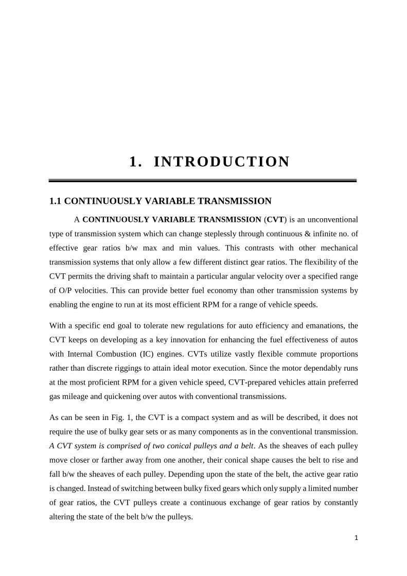
As can be seen in Fig. 1, the CVT is a compact system and as will be described, it does not
require the use of bulky gear sets or as many components as in the conventional transmission.
A CVT system is comprised of two conical pulleys and a belt. As the sheaves of each pulley
move closer or farther away from one another, their conical shape causes the belt to rise and
fall b/w the sheaves of each pulley. Depending upon the state of the belt, the active gear ratio
is changed. Instead of switching between bulky fixed gears which only supply a limited number
of gear ratios, the CVT pulleys create a continuous exchange of gear ratios by constantly
altering the state of the belt b/w the pulleys.

2
Figure 1.1: CVT system in which the 2 belt pulleys represent the CVT`s primary
and secondary gear reduction.
Few mechanisms that allow the control of the pulley diameter include engine speed, flyweights,
3 springs and a torque ramp. When all of these mechanisms work simultaneously, they act to
increase vehicle speed smoothly while maintaining engine speed at a particular value. This
feature of engine speed maintenance is possible due to the continuity of gear ratios.
Figure 1.2: CVT Speed Diagram
CVTs are not so new to the automotive world, but their efficiency & reliability have been
limited throughout. Latest developments in gear reduction and manufacturing have led to even
more-robust CVTs, which in turn makes it possible to be use them in more diverse automotive
applications. As CVT development continues, costs would go down and performance would
increase further, which would make further development and application of CVT technology
bodacious.
3
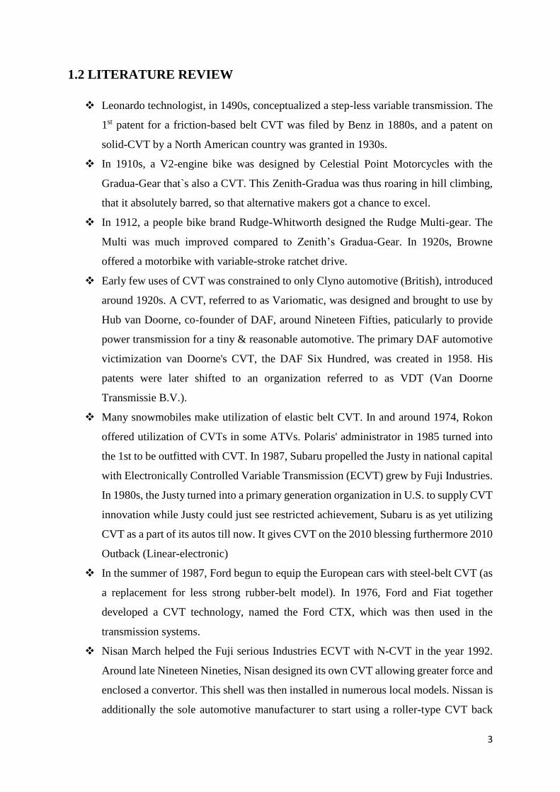
1.2 LITERATURE REVIEW
Leonardo technologist, in 1490s, conceptualized a step-less variable transmission. The
1st patent for a friction-based belt CVT was filed by Benz in 1880s, and a patent on
solid-CVT by a North American country was granted in 1930s.
In 1910s, a V2-engine bike was designed by Celestial Point Motorcycles with the
Gradua-Gear that`s also a CVT. This Zenith-Gradua was thus roaring in hill climbing,
that it absolutely barred, so that alternative makers got a chance to excel.
In 1912, a people bike brand Rudge-Whitworth designed the Rudge Multi-gear. The
Multi was much improved compared to Zenith’s Gradua-Gear. In 1920s, Browne
offered a motorbike with variable-stroke ratchet drive.
Early few uses of CVT was constrained to only Clyno automotive (British), introduced
around 1920s. A CVT, referred to as Variomatic, was designed and brought to use by
Hub van Doorne, co-founder of DAF, around Nineteen Fifties, paticularly to provide
power transmission for a tiny & reasonable automotive. The primary DAF automotive
victimization van Doorne's CVT, the DAF Six Hundred, was created in 1958. His
patents were later shifted to an organization referred to as VDT (Van Doorne
Transmissie B.V.).
Many snowmobiles make utilization of elastic belt CVT. In and around 1974, Rokon
offered utilization of CVTs in some ATVs. Polaris' administrator in 1985 turned into
the 1st to be outfitted with CVT. In 1987, Subaru propelled the Justy in national capital
with Electronically Controlled Variable Transmission (ECVT) grew by Fuji Industries.
In 1980s, the Justy turned into a primary generation organization in U.S. to supply CVT
innovation while Justy could just see restricted achievement, Subaru is as yet utilizing
CVT as a part of its autos till now. It gives CVT on the 2010 blessing furthermore 2010
Outback (Linear-electronic)
In the summer of 1987, Ford begun to equip the European cars with steel-belt CVT (as
a replacement for less strong rubber-belt model). In 1976, Ford and Fiat together
developed a CVT technology, named the Ford CTX, which was then used in the
transmission systems.
Nisan March helped the Fuji serious Industries ECVT with N-CVT in the year 1992.
Around late Nineteen Nineties, Nisan designed its own CVT allowing greater force and
enclosed a convertor. This shell was then installed in numerous local models. Nissan is
additionally the sole automotive manufacturer to start using a roller-type CVT back

4
then. It`s solid-CVT, Extroid, was obtainable within the local country market in Y34
Nisan Gloria and also in V35 Skyline GT-8. However, the shell wasn't used again once
the Cedric/Gloria was substituted by Nisan Fuga in 2004. The Nisan Murano (2003)
and therefore the Nisan knave (2007) additionally make use of CVT in their
transmissions. Amid a Nisan declaration (12/07/2006), Nisan proclaimed a gigantic
movement to CVT frameworks after they assigned their XTronic (CVT) for all models
of Versa, Cube and Maxima vehicles in North America. One noteworthy normal
rationale in Nisan to shape a change to CVTs was as under area of their 'Green Program
2010' outfitted towards lessening nursery gas discharges by 2010. The CVT found in
Nisan's Maxima, Murano and in this manner the V6 adaptation of the Altima is mulled
over to be the world's starting "3.5L class" belt-sort CVT and may hold a considerable
measure of more prominent power masses contrasted with option belt-sort CVTs.
After figuring out pulley-sort CVT for quite a long time, Honda also presented their
own particular form on 1995 Honda Civic VT-i. Named Honda Multi Matic, this CVT
shell acknowledged higher power than antiquated CVTs, and also incorporates a
convertor for "jerk" activity. The CVT is right away used inside the Honda town ZX
that is industrial facility made in Republic of India and Honda town Vario plant made
in West Pakistan.
Toyota made utilization of an impact Split Transmission (IST) inside the 1997 Prius,
and each one future Toyota and Lexus cross breeds sold-out universally still utilize the
framework. The HSD is moreover talked as Electronically Controlled Variable
Transmission (ECVT). The common time allows either the electrical engine or the Inner
Combustion Engine (ICE) to impel the vehicle. In ICE-just mode, an a piece of the
motor's energy is naturally coupled to the drivetrain, with the inverse half examining a
generator and an engine. The amount of force being diverted through the electrical way
affirm the successful rigging quantitative connection. Toyota moreover offers a non-
crossover CVT alluded to as Multi-drive for models like Avensis. Audi has, following
2000, offered a chain-sort CVT (multi-electronic) as an alternative on a no. of its bigger
motor models. Case in point, the A4 3.0 L V6 Fiat in 2000 offered a Cone-construct
CVT as decision with respect to one of its fruitful model Punto (16V).
Ford introduced a chain-type CVT, called the CFT30, in their 2005 Ford race, Ford
500. The transmission was designed in cooperation with German manufacturer ZF
Friedrichshafen and was created in Batavia, Ohio at Batavia Transmissions LLC
(22/03/2007). The Batavia plant additionally created the belt-type CVT that was then
5
used in the Ford Focus C-MAX. Ford additionally sold-out Escort and Orion models in
Europe with CVTs around 1980-1990.
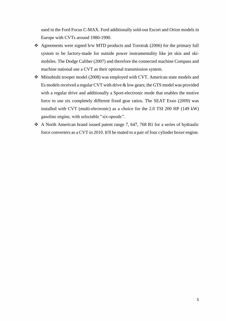
Agreements were signed b/w MTD products and Torotrak (2006) for the primary full
system to be factory-made for outside power instrumentality like jet skis and ski-
mobiles. The Dodge Caliber (2007) and therefore the connected machine Compass and
machine national use a CVT as their optional transmission system.
Mitsubishi trooper model (2008) was employed with CVT. American state models and
Es models received a regular CVT with drive & low gears; the GTS model was provided
with a regular drive and additionally a Sport-electronic mode that enables the motive
force to use six completely different fixed gear ratios. The SEAT Exeo (2009) was
installed with CVT (multi-electronic) as a choice for the 2.0 TSI 200 HP (149 kW)
gasoline engine, with selectable '’six-speeds’'.
A North American brand issued patent range 7, 647, 768 B1 for a series of hydraulic
force converters as a CVT in 2010. It'll be mated to a pair of four cylinder boxer engine.
6
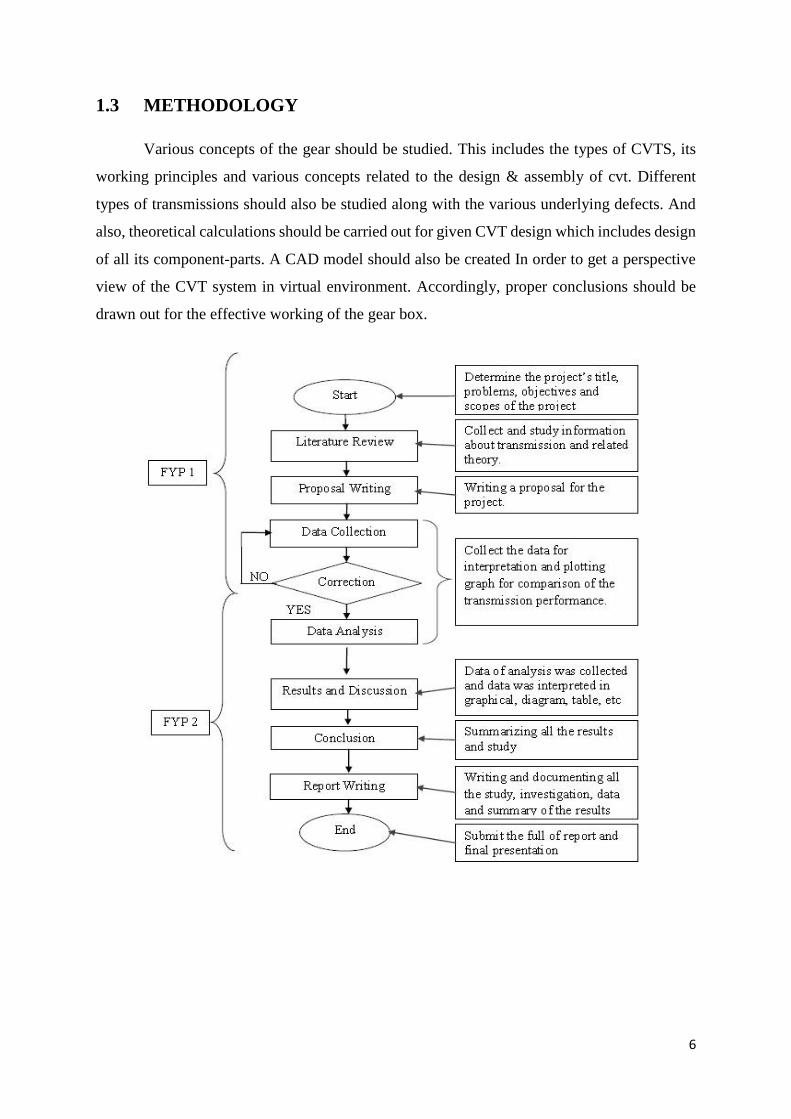
1.3 METHODOLOGY
Various concepts of the gear should be studied. This includes the types of CVTS, its
working principles and various concepts related to the design & assembly of cvt. Different
types of transmissions should also be studied along with the various underlying defects. And
also, theoretical calculations should be carried out for given CVT design which includes design
of all its component-parts. A CAD model should also be created In order to get a perspective
view of the CVT system in virtual environment. Accordingly, proper conclusions should be
drawn out for the effective working of the gear box.
7
2 . WORKING AND APPLICATIONS
OF CVT
2.1 HOW CVT WORKS
Conventional transmission systems make use of a gear set that provides us with a
variety of gear ratios. The transmission system (or the driver) shifts gears to supply the
foremost applicable magnitude relation for a given condition: Lower gears for beginning out,
Intermediate ones for acceleration and larger ones for fuel-efficient cruising.
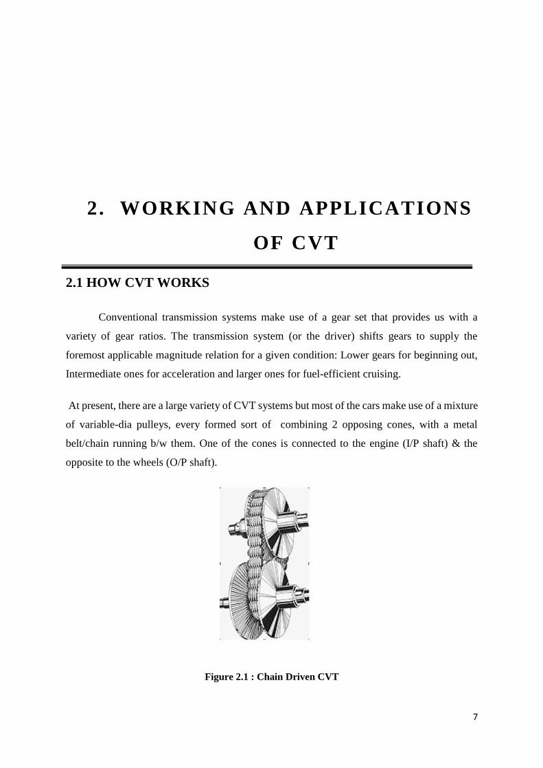
At present, there are a large variety of CVT systems but most of the cars make use of a mixture
of variable-dia pulleys, every formed sort of combining 2 opposing cones, with a metal
belt/chain running b/w them. One of the cones is connected to the engine (I/P shaft) & the
opposite to the wheels (O/P shaft).
Figure 2.1 : Chain Driven CVT
8
Both halves of the machine are motion permitted; because the machine halves tend to come
back nearer along the belt is forced to ride higher along the height of the cones, henceforth
resulting in larger dia of the pulley. Change in dia of the pulleys varies the magnitude relation
accordingly. For instance, the chain of a 10-speed bike routes over larger/smaller gears to vary
the magnitude relation. Keeping the I/P cone smaller and the O/P cone larger offers us a
magnitude relation for higher low-speed acceleration. Because the automotive assembly
accelerates, the pulleys vary their dia from higher to lower as speed rises. The above
phenomenon can be constant factor a traditional automatic/ manual transmission will, however
whereas conventional transmission system changes the magnitude relation a little by shifting
of gears, CVT varies the magnitude relation continuously - therefore the name.
2.2 CVT Types
2.2.1 Variable-Dia Pulley (VDP)
This is the most typical kind of CVT, in which square-measure 2 V-belt pulleys are
employed that split perpendicular to their corresponding rotational axes, with a V shaped belt
running b/w them. Quantitative relation of the gear is modified when sections of 1 pulley-block
are moved nearer along & also the 2-sections of the opposite pulley-block apart. As a result of
this, a peculiar cross section of the belt is formed that causes the belt to go higher along one
block & lower on the opposite. During the above transformation, the effective dias of the
pulleys changes which, in turn, changes the gear quantitative relation. Neither he space b/w the
pulleys doesn't amend nor will the belt length, therefore dynamically, the quantitative relation
of the gear means that each pulley should be adjusted (one larger, the opposite smaller) at the
same time to take care of the correct quantity of tension on the operating belt.
The V shaped belt has to be immensely stiff within the axial direction of the pulley so as to
form solely tiny radial movements. This will be achieved by a series of bands. One facet of the
V shaped belt should push in order to dive the pulleys out. Every component of the chain has
round shape sides. If the V-belt is running about the outermost radii then the belt moves inwards
and hence, the area of contact decreases. The area of contact is directly proportional to the
quantity of components, therefore the operating chain has voluminously little components. The
radial thickness of the V-belt used could be a compromise b/w most max quantitative relation
& force. For identical reason, the axis b/w both pulleys is as skinny as doable. A relatively
thick layer of material is applied to the pulleys so that the pulley-block and also the belt never
9
bit apart and it should be skinny so as to not waste power. In addition, the chain components
stabilize regarding twelve steel bands. Every band is skinny enough so as to bend simply. If
bending, it's an ideal round shape surface on its facet. Within the stack of bands, each band
maps to a rather totally different quantitative relation. Hence, the bands slide over one-another
and wish oil b/w them. Conjointly the outermost bands slide via the stabilizing chain, whereas
the middle bands may be made use for chain linkage.
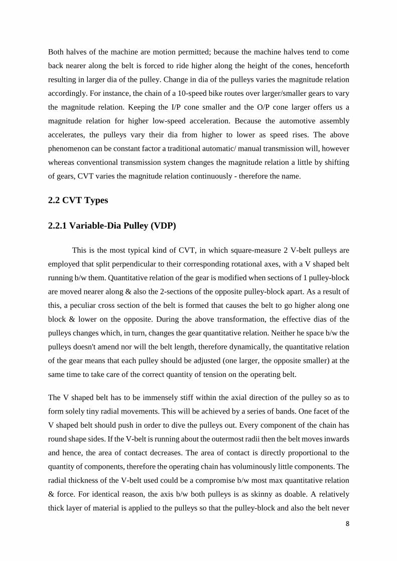
2.2.2 Pulley-Type CVTs
Most of the CVTs solely have 3 basic parts:
A dynamic metal/rubber belt.
An I/P "driving" pulley-block.
An O/P "driven" pulley-block.
CVTs even have numerous microprocessors and sensors, however the 3 parts delineated on top
are the crucial parts that enable the transmission system to function.
Figure 2.2: Variable pulley
The variable-dia pulleys square measure the centre of the CVT. Every machine is formed of 2
200 cones facing one another. A belt (made of metal/belt) rides within the groove b/w the 2
cones. V shaped belts are the most popular when the belt is made up of rubber. V shaped belts
get their name from the actual fact that the belts can bear a formed cross-section which
increases the belt`s resistance grip.
When both cones of the machine are initially so much apart (when the dia increases), the belt
starts to ride lower within the groove, & also the radii of the belt loop going round the machine

10
decreases and vice-versa. CVTs could use hydraulics, spring tension or force pull to form the
necessary force in order to regulate the halves of the machine.
One of the pulleys, referred to as the driving machine is made to connect to the engine shaft.
The second machine, named the driven machine as a result of the primary machine is popping
it. As associate O/P machine, energy is delivered to the shaft by the driven pulley-block.
Figure 2.3: Driving Pulley And Driven Pulley
The distance b/w the centres of the pulleys to its point of contact with the belt in the groove is
called the Pitch radius (PR). When the pulleys are distant from each other, the belt starts to ride
lower and the pitch radius decreases and vice-versa. The gear is determined by the ratio of the
pitch radius on the driven pulley to the pitch radius on the driving pulley.
When radius of 1 pulley-block increases, radius of the opposite decreases in order to maintain
the tightness of the belt because the 2 pulleys keep modifying the radii relatively so that they
produce associate infinite ratios - from low to high continuously. For instance, the speed of the
driven pulley decreases when the PR is little on the driving pulley-block & enormous on the
driven pulley, thus leading to a lower “gear” and vice-versa. In theory, a CVT has associate
infinite no. of "gears" that it will run the belt to acquire at any time, at any RPM.
The step-less nature and simplicity in design of CVTs give them a reputation of perfect
transmission system for a huge no. of devices & machines. They're additionally being utilized
in a large no. of vehicles, motor scooters and snowmobiles too. All types of applications, the
transmission systems have been heavily reliable on high-density rubber belts (polymers) that
may stretch/slip, thereby degrading their potency.
Increased use of advanced materials made CVTs even a lot more effective, economical and
reliable. Few among all the foremost necessary advancements has been the planning, and also
the development of metal-belts to attach the pulley-blocks. Above belts comprises of many

11
(typically 9/12) skinny steel bands that manage to hold bow-tie-shaped items and high-strength
of metal.
Figure 2.4: Metal Belt Design
These belts, made of metal, do not cause slipping and are extremely sturdy and hence, they
facilitate CVTs to handle a lot of engine torsion quite well.
2.2.3 SOLID/ROLLER-TYPE CVT
Toroidal CVTs are created from rollers and discs that work together in order to transmit
power b/w the discs. These discs are often seen as 2 nearly conic elements, purpose to purpose,
with the perimeters being dish-shaped. One of the discs is the I/P and the other one is the O/P.
Power is transmitted from one facet to the opposite with the help of rollers. When the axis of
the roller is normal to the axis of the near-conical elements, it contacts the near-conical
elements at equal-dia locations and therefore offers 1:1 relation. The rollers are often stirred on
the axis of the near-conical elements at a particular dynamical angle as required to keep up
contact. This can force the roller to touch the near-conical elements at variable and distinct dia,
giving a relation apart from 1:1. System is also partial or full solid. Full solid systems are the
foremost economical style whereas partial toroidals should still need a convertor, and thence
lose potency.
Here's however it works:
• One of the discs is connected to the engine (Simple Driving Machine).
• The other one is connected to the drive shaft (Simple Driven Machine).
• Rollers placed b/w these discs act just like belts, transmitting power from 1 disc to
the opposite.

12
Figure 2.5: Toroidal CVT
The wheels go around the horizontal axis and tilt in/out round the vertical axis. This motion of
the wheels permits them to come in contact with the discs at numerous points. When the wheels
bear with the driving disc close to the middle, they need to touch the driven disc close to the
rim, leading to a discount in speed and a rise in torsion (i.e. low gear) and vice-versa. An easy
inclination of the wheels then stepwise changes the gear relation, providing for swish, almost
instant relation variation.
2.2.4 CONE-TYPE CVTS
This classification incorporates all CVTs that are comprised of one/more cone shaped
bodies that capacity at the same time along their comparing generatrix such that obliged variety
is attained to. If there should arise an occurrence of SINGLE-CONE sort, a spinning body
(more often than not a wheel) is made to proceed onward the generatrix of the cone to make
the wanted variety b/w the sub-par and the prevalent dia of the cone.
If there should arise an occurrence of CVT with swaying cones, the torque is being transmitted
from a variable no. of cones to a barrel-molded center point utilizing rubbing. The side surfaces
of the barrel-molded center is kept raised with a predefined span of bend (for the most part
lower than the concavity sweep of the swaying cones). Hypothetically, there could be most
extreme 1-contact-point b/w every cone and the center.
Utilizing this innovation, another and progressed CVT - the Warko, was being displayed in the
condition of Berlin in the year 2007 amid the 6th International CTI Symposium of Innovative
Automotive Transmissions.

13
A peculiar feature of the Warko transmission is that there is no clutch use. The engine is directly
connected to the wheels, and an epicyclic system in O/P helps to obtain the rear drive. This
system (Power Split) offers the geared neutral condition i.e. Zero-Dynamic condition. When
the engine starts (connected to the sun gear), the variator (which rotates the ring in the opposite
direction that of sun gear), in a specified position of its range, will nullify for the engine
rotation, having no turns in O/P (planetary = O/P). The satellite gears are hence constrained to
roll within an internal ring gear.
2.3 WARKO SYSTEM WORKING PRINCIPLE
All the constituent parts required for the transmission of motion are shown below along
with the complete configuration of the system. Each and every phase of the Warko CVT's
assembly is deeply followed in order to understand its principle.
Figure 2.6: Warko CVT Assembly
Examining the motion transmission process of this CVT system, it can be seen that the
motion is being transmitted from the engine shaft to the main gear (i.e. sun gear).
Figure 2.7: Power from Engine Shaft to Main Gear
14
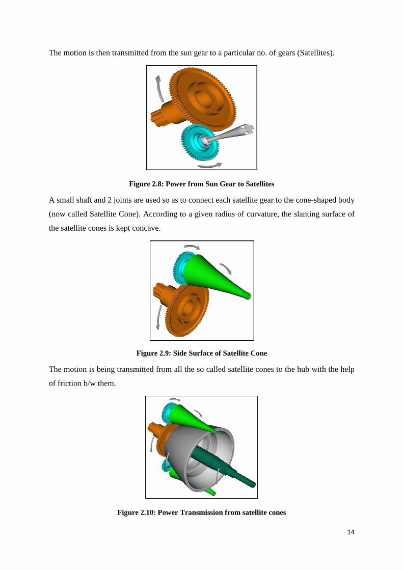
The motion is then transmitted from the sun gear to a particular no. of gears (Satellites).
Figure 2.8: Power from Sun Gear to Satellites
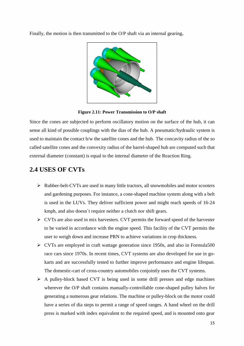
A small shaft and 2 joints are used so as to connect each satellite gear to the cone-shaped body
(now called Satellite Cone). According to a given radius of curvature, the slanting surface of
the satellite cones is kept concave.
Figure 2.9: Side Surface of Satellite Cone
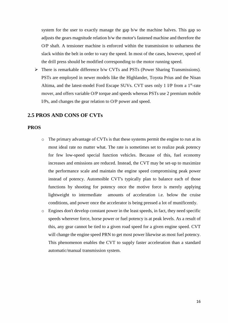
The motion is being transmitted from all the so called satellite cones to the hub with the help
of friction b/w them.
Figure 2.10: Power Transmission from satellite cones
15
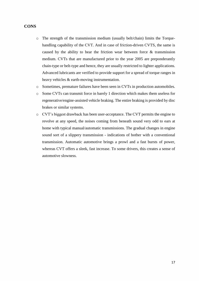
Finally, the motion is then transmitted to the O/P shaft via an internal gearing.
Figure 2.11: Power Transmission to O/P shaft
Since the cones are subjected to perform oscillatory motion on the surface of the hub, it can
sense all kind of possible couplings with the dias of the hub. A pneumatic/hydraulic system is
used to maintain the contact b/w the satellite cones and the hub. The concavity radius of the so
called satellite cones and the convexity radius of the barrel-shaped hub are computed such that
external diameter (constant) is equal to the internal diameter of the Reaction Ring.
2.4 USES OF CVTs
Rubber-belt-CVTs are used in many little tractors, all snowmobiles and motor scooters
and gardening purposes. For instance, a cone-shaped machine system along with a belt
is used in the LUVs. They deliver sufficient power and might reach speeds of 16-24
kmph, and also doesn`t require neither a clutch nor shift gears.
CVTs are also used in mix harvesters. CVT permits the forward speed of the harvester
to be varied in accordance with the engine speed. This facility of the CVT permits the
user to weigh down and increase PRN to achieve variations in crop thickness.
CVTs are employed in craft wattage generation since 1950s, and also in Formula500
race cars since 1970s. In recent times, CVT systems are also developed for use in go-
karts and are successfully tested to further improve performance and engine lifespan.
The domestic-cart of cross-country automobiles conjointly uses the CVT systems.
A pulley-block based CVT is being used in some drill presses and edge machines
wherever the O/P shaft contains manually-controllable cone-shaped pulley halves for
generating a numerous gear relations. The machine or pulley-block on the motor could
have a series of dia steps to permit a range of speed ranges. A hand wheel on the drill
press is marked with index equivalent to the required speed, and is mounted onto gear
16
system for the user to exactly manage the gap b/w the machine halves. This gap so
adjusts the gears magnitude relation b/w the motor's fastened machine and therefore the
O/P shaft. A tensioner machine is enforced within the transmission to unharness the
slack within the belt in order to vary the speed. In most of the cases, however, speed of
the drill press should be modified corresponding to the motor running speed.
There is remarkable difference b/w CVTs and PSTs (Power Sharing Transmissions).
PSTs are employed in newer models like the Highlander, Toyota Prius and the Nisan
Altima, and the latest-model Ford Escape SUVs. CVT uses only 1 I/P from a 1st-rate
mover, and offers variable O/P torque and speeds whereas PSTs use 2 premium mobile
I/Ps, and changes the gear relation to O/P power and speed.
2.5 PROS AND CONS OF CVTs
PROS
o The primary advantage of CVTs is that these systems permit the engine to run at its
most ideal rate no matter what. The rate is sometimes set to realize peak potency
for few low-speed special function vehicles. Because of this, fuel economy
increases and emissions are reduced. Instead, the CVT may be set-up to maximize
the performance scale and maintain the engine speed compromising peak power
instead of potency. Automoible CVT's typically plan to balance each of those
functions by shooting for potency once the motive force is merely applying
lightweight to intermediate amounts of acceleration i.e. below the cruise
conditions, and power once the accelerator is being pressed a lot of munificently.
o Engines don't develop constant power in the least speeds, in fact, they need specific
speeds wherever force, horse power or fuel potency is at peak levels. As a result of
this, any gear cannot be tied to a given road speed for a given engine speed. CVT
will change the engine speed PRN to get most power likewise as most fuel potency.
This phenomenon enables the CVT to supply faster acceleration than a standard
automatic/manual transmission system.
17
CONS
o The strength of the transmission medium (usually belt/chain) limits the Torque-
handling capability of the CVT. And in case of friction-driven CVTS, the same is
caused by the ability to bear the friction wear between force & transmission
medium. CVTs that are manufactured prior to the year 2005 are preponderantly
chain-type or belt-type and hence, they are usually restricted to lighter applications.
Advanced lubricants are verified to provide support for a spread of torque ranges in
heavy vehicles & earth-moving instrumentation.
o Sometimes, premature failures have been seen in CVTs in production automobiles.
o Some CVTs can transmit force in barely 1 direction which makes them useless for
regenerative/engine-assisted vehicle braking. The entire braking is provided by disc
brakes or similar systems.
o CVT’s biggest drawback has been user-acceptance. The CVT permits the engine to
revolve at any speed, the noises coming from beneath sound very odd to ears at
home with typical manual/automatic transmissions. The gradual changes in engine
sound sort of a slippery transmission - indications of bother with a conventional
transmission. Automatic automotive brings a prowl and a fast bursts of power,
whereas CVT offers a sleek, fast increase. To some drivers, this creates a sense of
automotive slowness.
18
3. DESIGN OF CVT
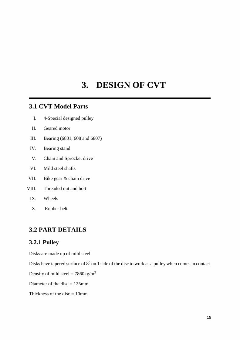
3.1 CVT Model Parts
I. 4-Special designed pulley
II. Geared motor
III. Bearing (6801, 608 and 6807)
IV. Bearing stand
V. Chain and Sprocket drive
VI. Mild steel shafts
VII. Bike gear & chain drive
VIII. Threaded nut and bolt
IX. Wheels
X. Rubber belt
3.2 PART DETAILS
3.2.1 Pulley
Disks are made up of mild steel.
Disks have tapered surface of 80 on 1 side of the disc to work as a pulley when comes in contact.
Density of mild steel = 7860kg/m3
Diameter of the disc = 125mm
Thickness of the disc = 10mm
19
Size of pulley or discs-
Figure 3.1: Tapered Disc
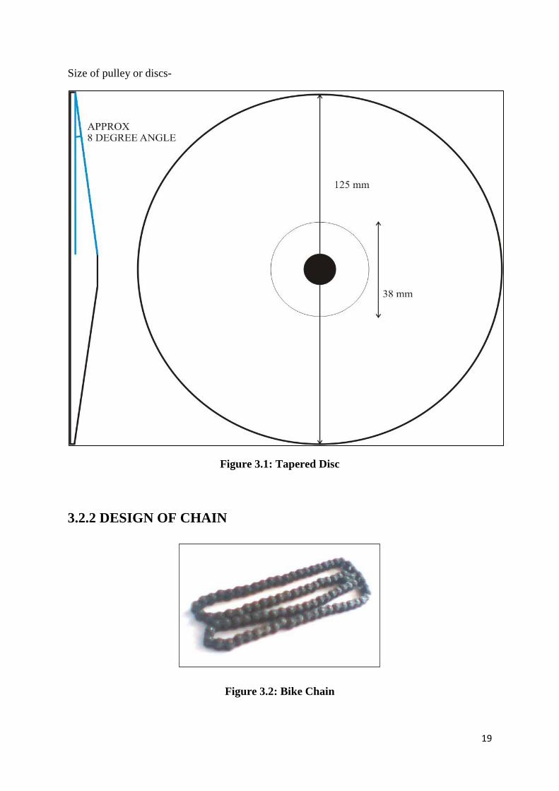
3.2.2 DESIGN OF CHAIN
Figure 3.2: Bike Chain
20
It is assumed that,
Teeth on the bigger sprocket, Z2 = 44
Teeth on the smaller sprocket, Z1 = 7
Velocity ratio = 44/7 = 6.285
For the above velocity ratio(6-7), min centre distance Cmin= 1.5*(D1+D2)/2+(30 to 50)
` Cmin= 1.5*(185+32)/2+40
Cmin= 202.75 mm
Adopted Value - C = 205 mm
Pitch of the Chain p = C/(30 to 60)
p = (205)/(30 to 60) = 3.41 to 6.83
Adopted Value - p = 6.83 mm
No. of Links M = (2C/p)+(Z1+Z2)/2+p*(Z2-Z1)2/(4π2C)
M = 60.025+25.5+1.01
M = 86.03
Adopted Value - M = 86
Length of the 1st Chain = Mp
1st Chain Length = 86*683/100 = 588 mm (approximately)
By following the above method, the 2nd chain can also be designed similarly.
Aggregate number of teeth on both the sprockets = 17
Center Distance C = 205 mm
p = (205)/(30 to 60) = 6.21 (approximately)
M = (2C/p)+(Z1+Z2)/2+p*(Z2-Z1)2/(4π2C)
M = 83.02 = 84 (approximately)
21
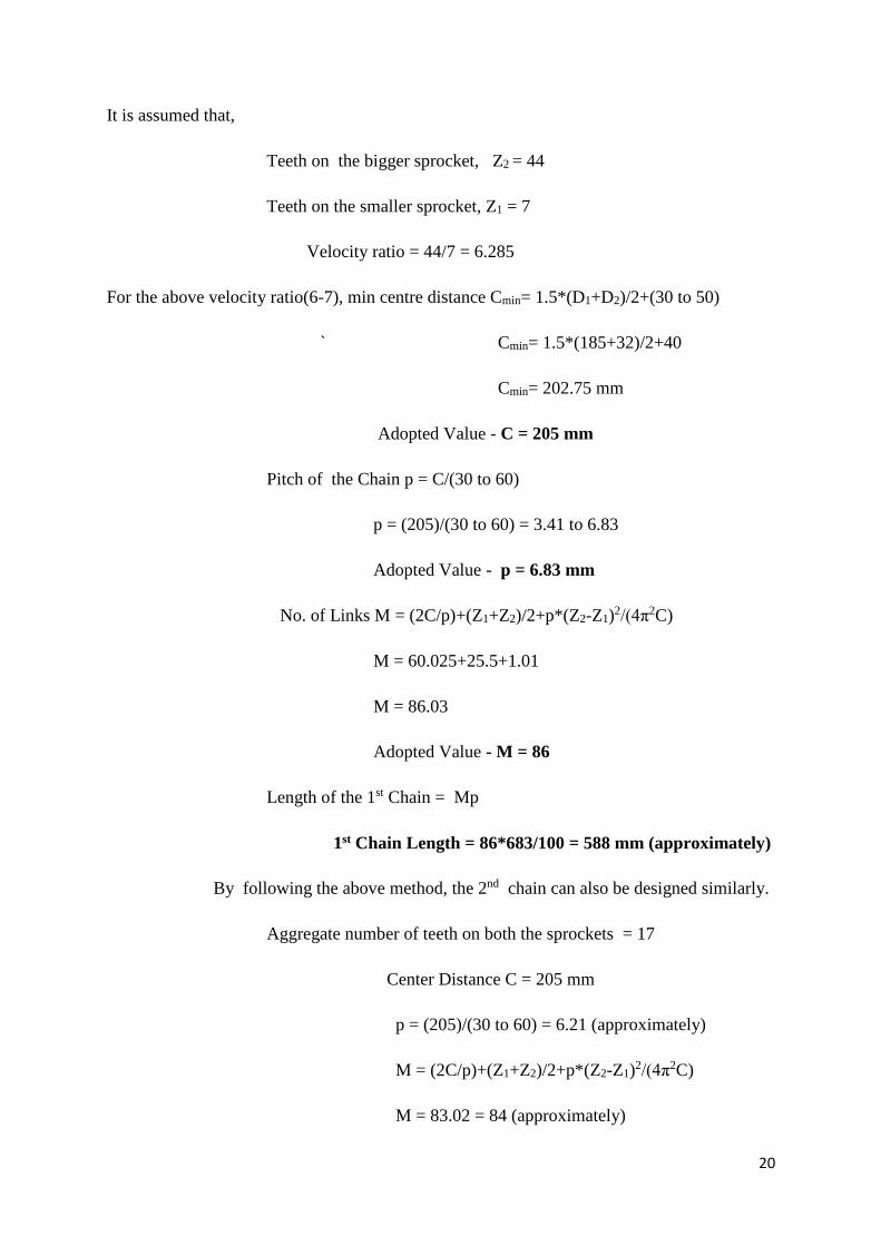
Length of the 1st Chain = M*p = 84*6.21 = 524 mm (approximately)
Dimensions - Length of the Chain= 588 mm No. of Grooves = 86
Figure 3.3: Design of Chain and Sprockets
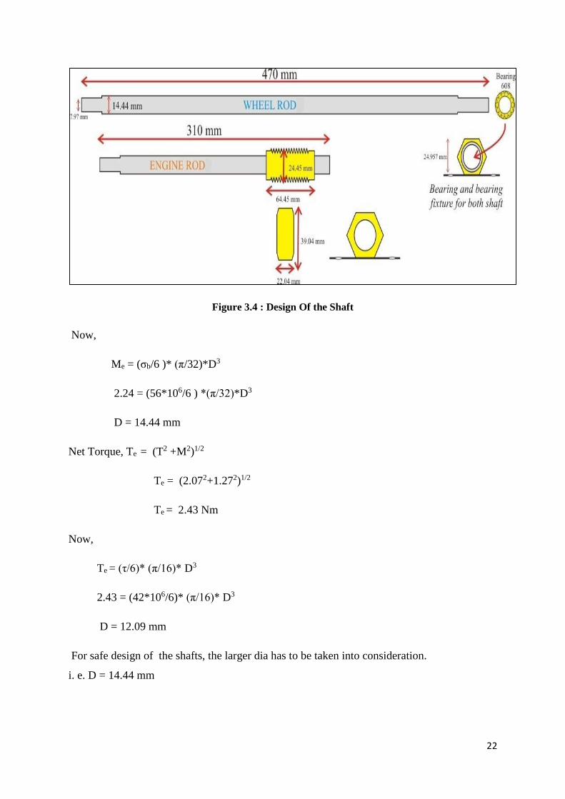
3.2.3 DESIGN OF SHAFT
Weight of the Disc, W1 = 8.8 N
Weight of the Pulley, W2 = 8.8*2 = 17.6 N
Given wt of the pulley acts as a pt. load on the shaft (weight of all other components is
considered to be negligible).
Bending Moment because of this pt. load is given by,
M = W2 *L/4 = (17.6*0.470)/4 = 2.07 N-m
Power of the motor used, P = 0.25 HP = 186.5 watt
Speed of the motor used, S = 1400 rpm (approx.)
For the material used i.e. mild steel,
Permissible Bending Stress = 56 Mpa
Permissible Shear Stress = 42 Mpa; FOS = 6
22
Figure 3.4 : Design Of the Shaft
Now,
Me = (σb/6 )* (π/32)*D3
2.24 = (56*106/6 ) *(π/32)*D3
D = 14.44 mm
Net Torque, Te = (T2 +M2)1/2
Te = (2.072+1.272)1/2
Te = 2.43 Nm
Now,
Te = (τ/6)* (π/16)* D3
2.43 = (42*106/6)* (π/16)* D3
D = 12.09 mm
For safe design of the shafts, the larger dia has to be taken into consideration.
i. e. D = 14.44 mm

23
3.2.3 Bike Sprockets
Figure 3.5: Bike Sprocket
Dimensions
Total No. of Teeth = 28, Length of the Sprocket = 60mm
3.2.4 DC Motor
In 1821, M. Faraday invented the 1st electromagnetic rotatory motor. The simplest form
of electric motors called homo-polar motors are described below. It comprised of a freely
hanging wire dipped into a mercury pool and a permanent magnet dipped in it. When current
was made to pass through the wire, the wire starts rotating around the magnet. This shows that
the current gave rise to some sort of circular magnetic field around the wire. Sometimes, brine
(salt water) can also be used in place of mercury.
Another ancient design of electric motor made use of a reciprocating plunger inside a solenoid.
Conceptually, it could be imagined as an electromagnetic version of a 2-stroke IC engine. In
1873, Z. Gramme invented the modern DC motor by accident by connecting a rotating
generator to a 2nd similar unit and hence, can be pictured as motor-driven.
The classic DC Motor has an armature rotating in the form of an electromagnet. The current
direction is reversed twice in each cycle so as to flow through the armature such that the
electromagnetic poles push and pull the permanent magnets towards the outer side of the motor.
The reversal of current direction is done through the use of a rotary switch, called Commutator.
The Commutator also reverses the polarity of the armature electromagnet each and every time
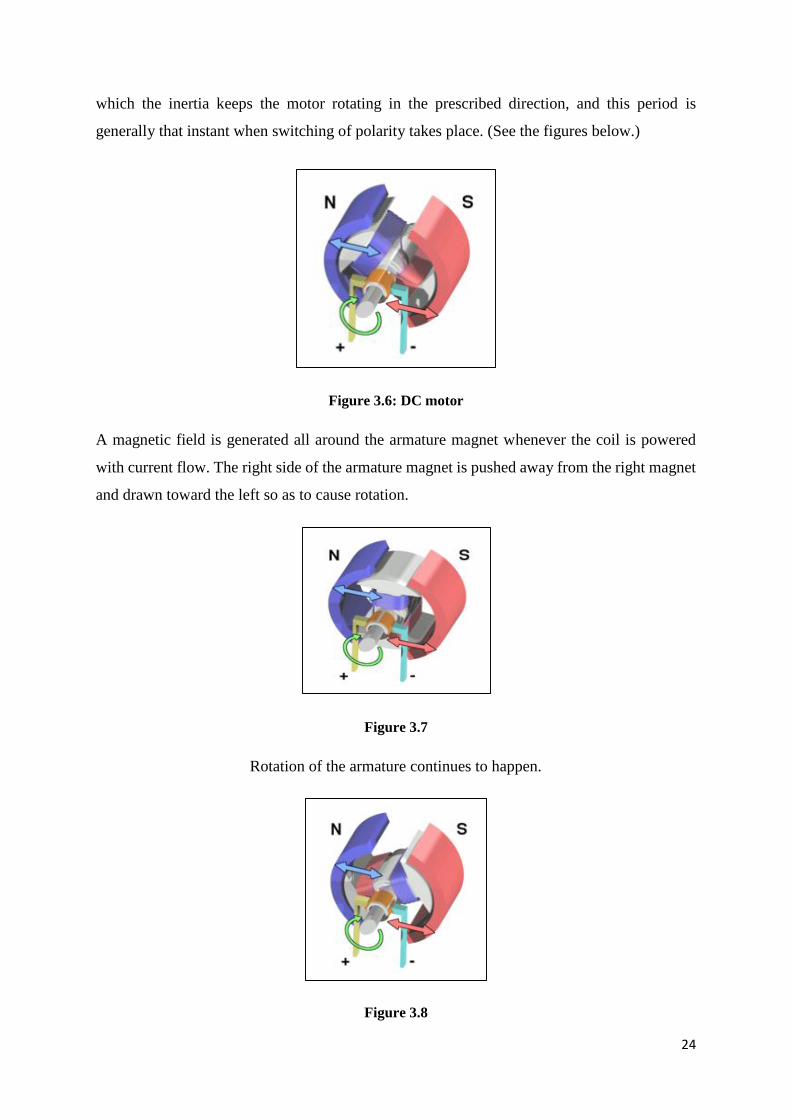
the poles of the armature pass the poles of the permanent magnets. There is a period during
24
which the inertia keeps the motor rotating in the prescribed direction, and this period is
generally that instant when switching of polarity takes place. (See the figures below.)
Figure 3.6: DC motor
A magnetic field is generated all around the armature magnet whenever the coil is powered
with current flow. The right side of the armature magnet is pushed away from the right magnet
and drawn toward the left so as to cause rotation.
Figure 3.7
Rotation of the armature continues to happen.
Figure 3.8

25
The current direction is reversed by the Commuatator whenever the armature becomes
horizontally aligned. Because of this change is current direction, the magnetic field also gets
reversed. The process then repeats itself.
3.2.5 Bearing
The bearings make functioning of many of the machines we use in our everyday life
possible. Without the installation of bearings, there would have been a constant necessity to
change parts which wore out due to friction.
Figure 3.9: Tapered Roller Bearing - Manual Transmission`
In this current article, it will be seen how exactly bearings work, and also will look at different
bearing types. Also, some of their common uses will be explored.
Bearing Basics
The concept guiding functioning of a bearing is too simple i.e. Rolling is way too easy
compared to Sliding because frictional differences. For instance, the wheels of a car are just
analogous to big bearings.
Figure 3.10: Simple Bearing
26
Friction is greatly reduced by using bearings because bearings have smooth metal
cylindrical/spherical entities and a smooth inner and outer metal surfaces for the metal entities
to roll against. A smooth spin is provided to the device by these entities because they "bear"
the load, and hence the name.
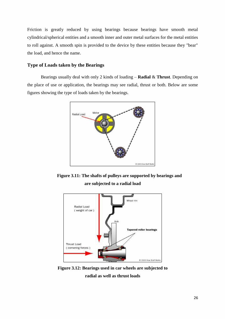
Type of Loads taken by the Bearings
Bearings usually deal with only 2 kinds of loading – Radial & Thrust. Depending on
the place of use or application, the bearings may see radial, thrust or both. Below are some
figures showing the type of loads taken by the bearings.
Figure 3.11: The shafts of pulleys are supported by bearings and
are subjected to a radial load
Figure 3.12: Bearings used in car wheels are subjected to
radial as well as thrust loads

27
Types of Bearings
Ball Bearings
Ball bearings, as shown in the figure below, are the most common type of bearings
used. Their use can be found everywhere ranging from hard drives to inline skates. Both
thrust & radial loads can be handled by these bearings, and is typically found in applications
where relatively small loads are to be taken.
Figure 3.13: Ball Bearing – Cutaway View
In this type, first the load is being transferred from the external race to the ball, and then from
the ball to the internal race. Since the ball is spherical in geometry, it maintains only a point
contact with both the internal & the external race, which provides a very smooth spinning.
Thus, the balls can sometimes deform or squish if the bearing is overloaded. 90xo

28
3.3 CVT CONSTRUCTION DETAILS
As per the model, the project can be divided in following 2 divisions:
[1]. Section A ENGINE DRIVE PULLEY
[2]. Section B WHEEL DRIVEN PULLEY
CVT design as well as its working is described below:
Figure 3.14: Model of CVT
29
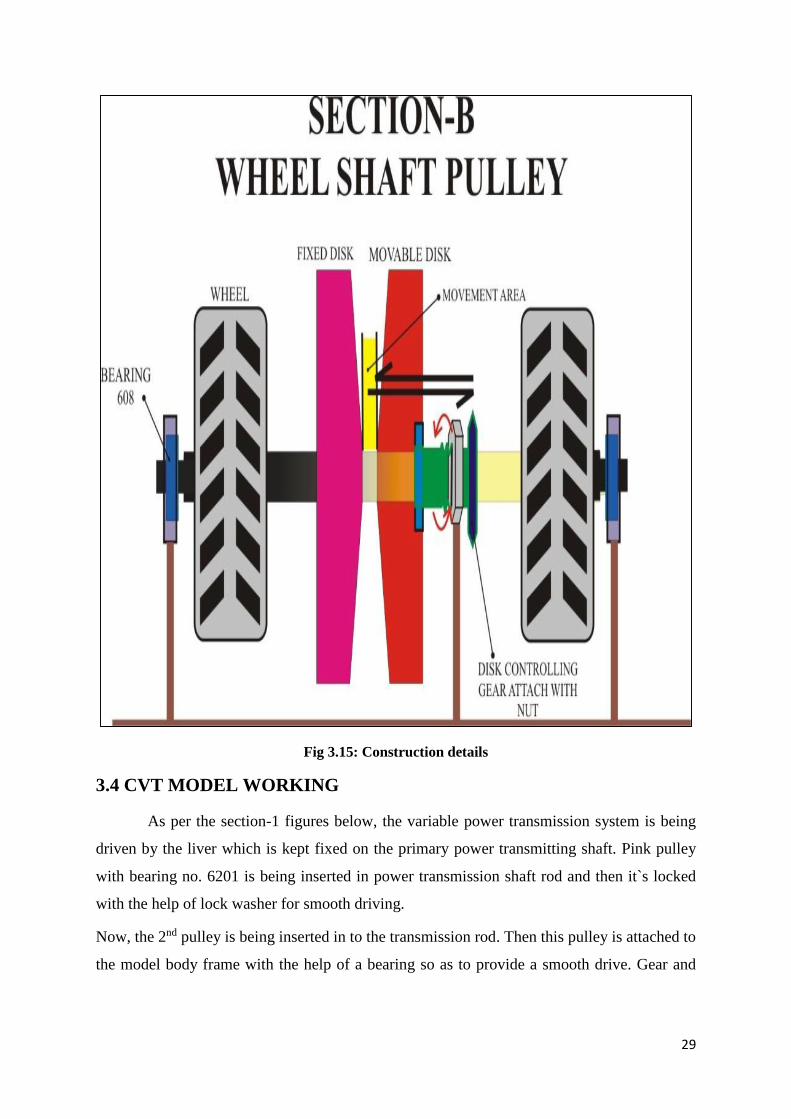
Fig 3.15: Construction details
3.4 CVT MODEL WORKING
As per the section-1 figures below, the variable power transmission system is being
driven by the liver which is kept fixed on the primary power transmitting shaft. Pink pulley
with bearing no. 6201 is being inserted in power transmission shaft rod and then it`s locked
with the help of lock washer for smooth driving.
Now, the 2nd pulley is being inserted in to the transmission rod. Then this pulley is attached to
the model body frame with the help of a bearing so as to provide a smooth drive. Gear and
30
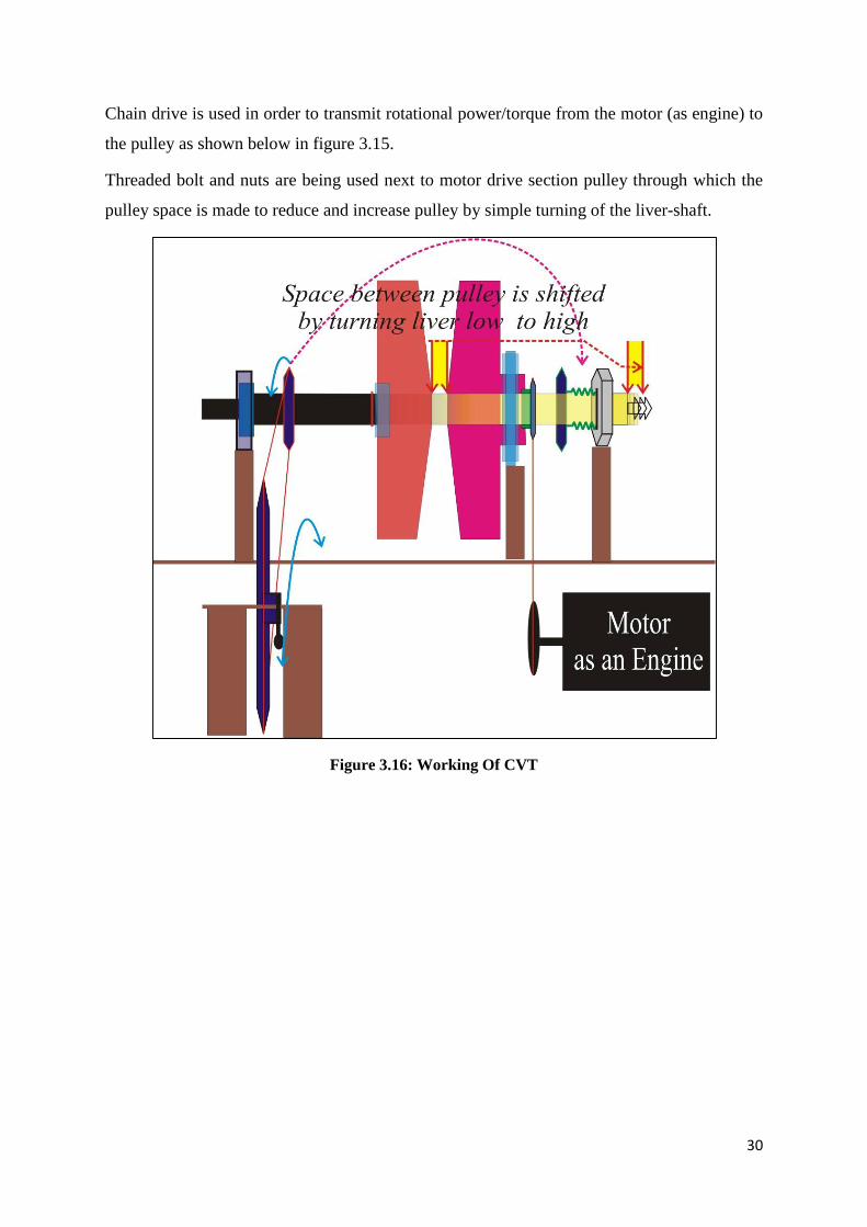
Chain drive is used in order to transmit rotational power/torque from the motor (as engine) to
the pulley as shown below in figure 3.15.
Threaded bolt and nuts are being used next to motor drive section pulley through which the
pulley space is made to reduce and increase pulley by simple turning of the liver-shaft.
Figure 3.16: Working Of CVT
31
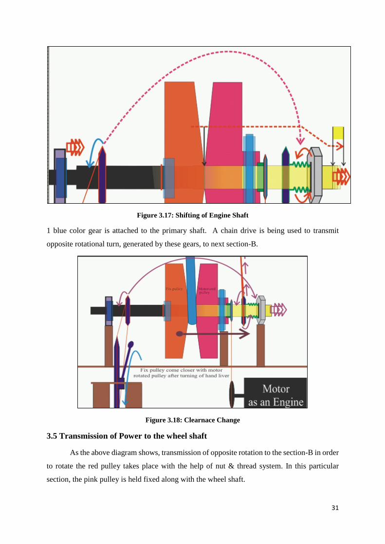
Figure 3.17: Shifting of Engine Shaft
1 blue color gear is attached to the primary shaft. A chain drive is being used to transmit
opposite rotational turn, generated by these gears, to next section-B.
Figure 3.18: Clearnace Change
3.5 Transmission of Power to the wheel shaft
As the above diagram shows, transmission of opposite rotation to the section-B in order
to rotate the red pulley takes place with the help of nut & thread system. In this particular
section, the pink pulley is held fixed along with the wheel shaft.
32
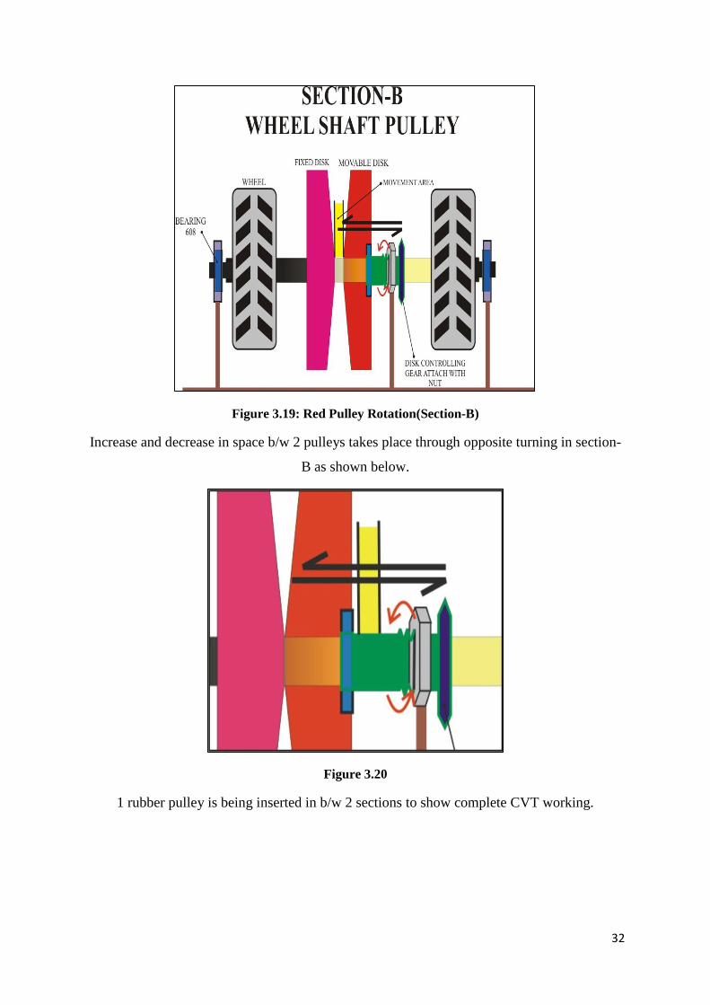
Figure 3.19: Red Pulley Rotation(Section-B)
Increase and decrease in space b/w 2 pulleys takes place through opposite turning in section-
B as shown below.
Figure 3.20
1 rubber pulley is being inserted in b/w 2 sections to show complete CVT working.

33
Figure 3.21: Low Gear Situation
Figure 3.22: High Gear Situation
34
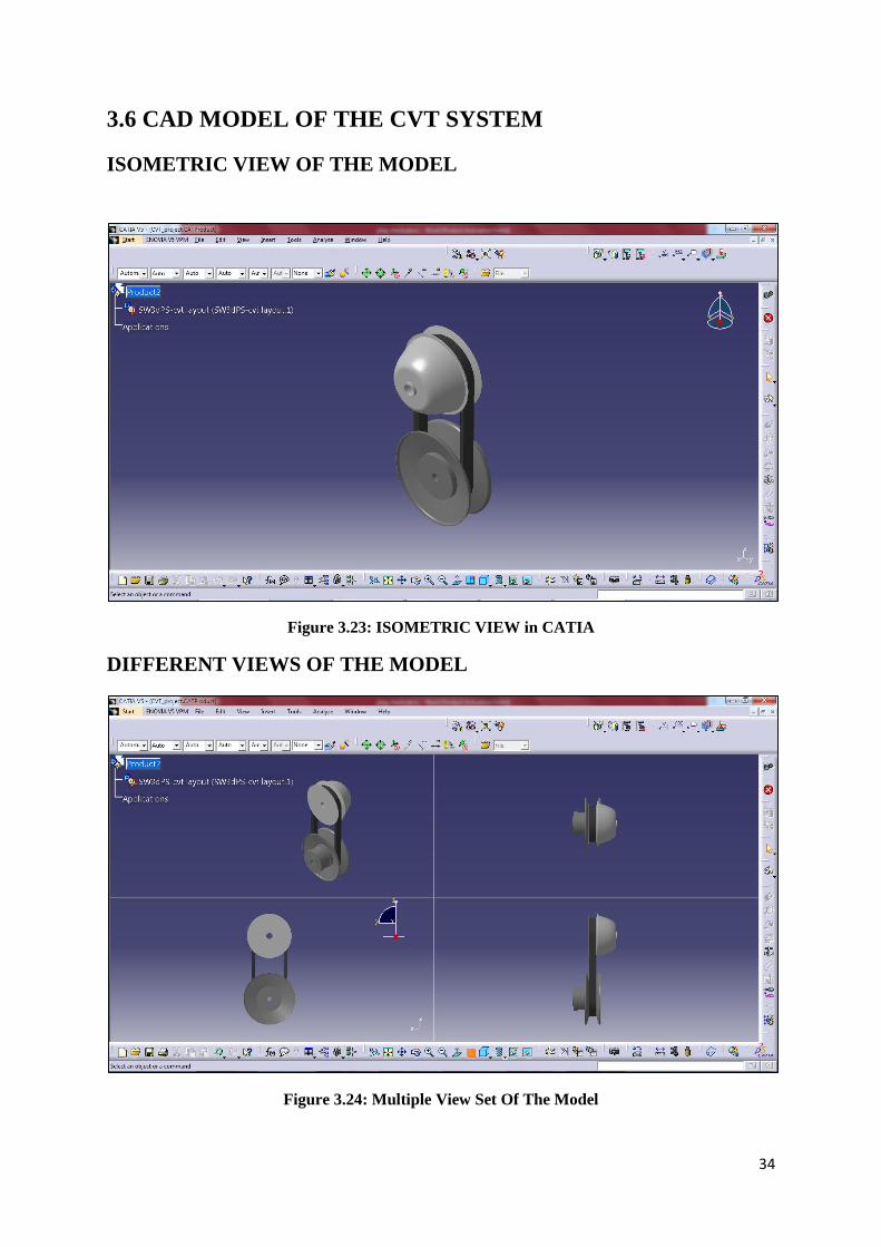
3.6 CAD MODEL OF THE CVT SYSTEM
ISOMETRIC VIEW OF THE MODEL
Figure 3.23: ISOMETRIC VIEW in CATIA
DIFFERENT VIEWS OF THE MODEL
Figure 3.24: Multiple View Set Of The Model
35
4. CONCLUSION
Working through this project, I managed to explore a vast pool of knowledge in the
field of Automobiles and its component-parts. It also provided me with valuable experience on
power transmission. I became aware of work criterion, challenges & other activities performed
during the research practice and the project implementation. This project has helped me to gain
lot of technical as well as practical knowledge. The Study of CVTs gave me a handful
knowledge about its component-parts and design criterion and its performance parameters.
Assuming a random set of data or dimensions, the CVT has been theoretically designed as well
as its assembly has been done. Accordingly, a CAD model has been designed to show the
various parts and functioning of the CVT technology. And also, for the modelled designed on
the basis of assumed data, a set of performance specifications have been mentioned.
At present, CVTs are only being used in a fewer no. of vehicles but the applications & pros of
CVT could only be improved based on R&D. As automobile manufacturers continue to
develop CVTs, more and more vehicles will use them, and also performance and fuel efficiency
will continue to increase inevitably. This sense of development will lead to increased sales
which, in turn, will prompt further R&D, and the cycle will keep repeating. Cruising
development of CVTs will foster competition among the manufacturers which in turn lowers
manufacturing costs. The CVT has only just begun to blossom.
SCOPE FOR FURTHER RESEARCH
Speaking of CVTs, there isn’t much of knowledge base around due to the existing
research work and literature whereas conventional/standard transmission systems have been
continuously improving since the very beginning of the 20th century. CVTs are going to be
even more prominent in a few years of time as per automotive landscape because of the
continuous improvement in the infrastructure along with the said knowledge base. Even today,
CVTs which predominantly represent 1st generation designs or models at best, outrun Standard
transmission systems. Automobile manufacturers and developers who fail to enhance CVT
technology now (this field is still in its early improvement stages), much risk being perceived
as CVTs R&D and applications continues to grow exponentially and will continue to do so.
CVTs, however, do not fall that exclusively into the domain of IC engines.
36
REFERENCES
[1]. D. Kobayashi, Y. Mabuchi and Y. Katoh: “A Study on the Torque Capacity of
a Metal Pushing V-Belt for CVTs” SAE Paper No. 980822, in SAE SP –1324,
Transmission and Driveline Systems Symposium, pg. 31-39 SAE, 1998.
[2]. K. Abo, M. Kobayashi and M. Kurosawa: “Development of a Metal Belt Drive
CVT Incorporating a Torque Converter for Use with 2-liter Class Engines” SAE
Paper No. 980823, in SAE SP-1324, Transmission and Driveline Systems
Symposium, pg. 41-48 SAE, 1998.
[3]. Hybrid V-Belt for a CVT – Advanced Numerical Model Considering Block
Tilting and Pulley Deformation” SAE Paper No. 1999-01-0751, in SAE SP-
1440, Transmission and Driveline System Symposium, pg. 143-153 SAE.
[4]. K. Ohya and H. Suzuki: “Development of CVT Pulley Piston Featuring
Variable Thickness and Work-Hardening Technologies” SAE Paper No.
980826, in SAE SP-1324, Transmission and Driveline Systems Symposium, pg.
71-79 SAE.
[5]. S. Sakaguchi, E. Kimura and K. Yamamoto: “Development of an Engine-CVT
Integrated Control System” SAE Paper No. 1999-01-0754, in SAE SP-1440,
Transmission and Driveline Systems Symposium, pg. 171-179 SAE.
[6]. M. Yasuoka, M. Uchida, S. Katakura and T. Yoshino: “An Integrated Control
Algorithm for an SI Engine and a CVT” SAE Paper No. 1999-01-0752, in SAE
SP-1440, Transmission and Driveline Systems Symposium, pg. 155-160 SAE.
[7]. N. Hattori, S. Aoyama, S. Kitada and I. Matsuo: “Functional Design of a Motor
Integrated CVT for a Parallel HEV” SAE Paper No. 1999-01-0753, in SAE SP-
144.
[8]. Transmission and Driveline Systems Symposium, pg. 161-167 SAE.C. Kim, E.
NamGoong, S. Lee, T. Kim and H. Kim: “Fuel Economy Optimization for
Parallel Hybrid Vehicles with CVT”, SAE Paper No. 1999-01-1148, in SAE
SP-1440.
[9]. Symposium, pg. 81-88 SAE, 1997. M.A. Kluger and D.R. Fussner: “An
Overview of Current CVT Mechanisms, Forces and Efficiencies” SAE Paper
No. 970688, in SAE SP-1241.