study of 2d and 3d methods for worn surface analysis of...
TRANSCRIPT

Acta Technica Jaurinensis
Vol. 8, No. 2, pp. 165-178, 2015DOI: 10.14513/actatechjaur.v8.n2.373
Available online at acta.sze.hu
165
Study of 2D and 3D Methods for Worn Surface Analysis of Tool Materials
I. Hatos1, H. Hargitai1, L. Solecki2
1Széchenyi István University, Department of Materials Science and Technology Egyetem square 1, H-9026 Győr, Hungary
Phone: +36 96 613 572 e-mail: [email protected]
2Széchenyi István University, Department of Vehicle Manufacturing Egyetem square 1, H-9026 Győr, Hungary
Abstract: This paper is dealing with the comparison of the results given by different worn surface analysing methods. Maraging steel tool materials were used for the experiments. Specimens were produced by direct metal laser sintering from metal powder and by conventional way from rod having equivalent chemical content. The samples were age-hardened and surface treated by nitrocarburising and oxynitriding and they were tested by pin-on-disc type tribometer. The tribological behaviour was compared by using different methods for worn surface analysis. Worn area of the surface was determined by the surface profiles of 2D measurements and the wear volume was calculated by using 3D images of focus variation microscopy measurements.
Keywords: worn surface analysis, focus variation microscope, maraging steel, heat treatment
1. Introduction
Direct metal laser sintering (DMLS) belongs to the rapid prototyping technologies. By producing the part layer by layer from metal powder extremely complex metal parts can be made in a relatively short time. A promising field of the applications of DMLS is tooling by producing mold insert for injection molding with special cooling systems, which offers so called conformal cooling, acurved cooling channels with various cross sections that can follow the surface of the part [1-3].
The increasing demand for tool applications in polymer industry often required to improve the surface properties, such as higher hardness and enhanced resistance against wear and corrosion. Effective ways of surface hardening are thermo-mechanical surface treatments or PVD coatings or combining two of them in duplex treatments [4-6]. The most important treatments are nitriding, nitrocarburising or carburising [7-8]. Nitriding and nitrocarburising are also widely used in case of molds for injection molding.

I. Hatos et al. – Acta Technica Jaurinensis, Vol. 8, No. 2, pp. 165-178, 2015
166
Increase in hardness, having lower resistance of erosion, corrosion, abrasion at low and high temperature and by preventing adhesion and reducing friction increase of the life of working components can be achieved [9].
Cajner et al. presented an overview about the maraging steels used in mold manufacturing and focuses on the wear resistance. They concluded that the thermo-chemical heat treatments such as nitriding, nitrocarburizing, boriding and carburizing improve the wear resistance of maraing steel. Among of these processes the best results was given by plasma nitriding [6].
Wear properties are very important and staying in the middle of the interest in case of tool applications. Wear resistance of the surfaces can be characterized different parameters, e.g. mass loss (as wear loss) [10-11], wear coefficient [8, 12-14], and by analyzing the worn surface. For qualitative characterization to study the worn morphology and thus the wear mechanism, microscopic techniques are generally used, like conventional optical microscope (stereo microscope) or scanning electron microscope [10-11, 15-17] and there are different kinds of confocal microscopes [13].
Psyllaki et al. used SEM not only for quantitative analysis of the worn surface of PE-CVD diamond-like carbon coatings on tool steel substrates. They calculated wear rates, which is the volume loss per unit of applied load and unit of sliding distance [mm3 N-1 m-1] based on the volume losses from SEM observations of sections perpendicular to the wear tracks [18].
AL-Bukhaiti et al. determined the wear rate by using a 3D-surface profilometer (InfiniteFocus, Alicona) and measure cross-section area (A) (mm2) and diameter (d) (m) of the wear track by using the equation (1):
∙ ∙
∙, (1)
where Fn (N) is the applied normal load, and l (m) is the total sliding distance. The volume loss was calculated by measuring the average of four cross-section areas of the wear track at four different points (90 intervals) [13].
Karamboiki et al. calculated first also the wear volume by using a profilometer. They measured cross-sectional area ten different locations along the wear track and then by multi-plying the average track area by the circumference of the slide cycle [mm3 N-1 m-1] [17].
Wang et al. determined the specific wear rate (W) by measuring mass loss (m (g)) according to the following equation (2) [10]:
∆
∙ (2)
In some cases the wear behavior was characterized by volumetric wear loss [mm3] [15]. Bressan et al. calculated cumulative lost volume by the division of the measured lost mass by the sample density [11]. Fontalvo et al. used white-light interferometry by taking measurements in three locations to determine the volume of transferred material [m3] using the software of the profiler [16].

I. Hatos et al. – Acta Technica Jaurinensis, Vol. 8, No. 2, pp. 165-178, 2015
167
As it can be clearly seen after the literature survey there are many methods and parameters for characterization the wear properties. Present paper is dealing with the tribological characterizing of maraging steel materials and focusing on the comparison of different methods which can be used for analysing the worn surface and thus qualifying the wear resistance of the materials. In our experiments DMLS MS1 and Böhler W722 samples with different surface hardness were tested after ageing, nitrocarburising and nitorcarburising with post oxidation (oxynitrided).
2. Experimental
2.1. Materials
For the experiments MS1maraging steel (1.2709) powder from EOS widely used in DMLS systems and W722 VMR (~1.2709) maraging tool steel from Böhler-Uddeholm having nearly the same chemical compositions (see Table 1.) were used. Both of them are ideal for injection molding applications.
Table 1. Chemical compositions of maraging steel tool materials
Material C Cr Ni Mn Si Al Co Mo Ti
MS1 <0.03 <0.5 17-19 <0.1 <0.1 0.05-0.15 8.5-9.5 4.5-5.2 0.6-0.8
W722 <0.005 18 9.25 4.85 1.00
2.2. Sample preparation
Machining
For the experiments disk specimens having diameter of 30 mm and thickness of 5.5 mm were produced by DMLS technology from MS1 metal powder and fabricated from rod in case of W722 material. All samples were ground and polished with the same conditions after machining (Figure 1.). Samples were polished using 1 μm diamond paste before heat treatments, and no subsequent polish was carried out after nitrocarburising and oxynitriding. After age-hardening the samples were re-polished.
Figure 1. The laser sintered samples (left), ground specimens (middle) and polished sample (right)

I. Hatos et al. – Acta Technica Jaurinensis, Vol. 8, No. 2, pp. 165-178, 2015
168
Heat treatment
Bulk and surface heat treating methods were used to achieve higher strength and hardness of the steels and enhance the wear resistance on the surface.
Age hardening, which is the common heat treating technology of maraging steels and thermochemical treatments, such as nitrocarburising and oxynitriding were applied. The main parameters of the heat treatment methods are summarized in Table 2.
Table 2. Heat treatment conditions
Heat treatment Abbrev.Temperature[°C]/
Duration [h] Atmosphere
age-hardening H 500°C/4h air
nitrocarburising N 550°C/8h(12h) 50% N2; 45% NH3; 5% CO2
oxynitriding ON 550°C/6.5h (13h)450C/1h
50% N2; 45% NH3; 5% CO2 water
2.3. Test and evaluation methods, equipment
Wear test
Abrasion resistance was determined by ball-on-disc type tribology test. For the experiments an UNMT-1 Universal nano & micro tester was applied (see Figure 2) and zirconium oxide ceramic balls were used as test tools. For each test a new ball was applied.
Figure 2. The pin (ball)-on disc type tribometer (UNMT-1 Universal nano & micro tester)(left) and the test specimen after the wear test(right)
The test parameters applied at the measurements were the followings: sliding speed:100 mm/s (318.47 1/min), set force: 20 N, duration: 360 m (time: 60 min) room temperature and atmosphere: laboratory air.
The typical characteristics of the tribological behaviour measured and calculated were friction coefficient and the area/volume of worn surface.

I. Hatos et al. – Acta Technica Jaurinensis, Vol. 8, No. 2, pp. 165-178, 2015
169
Characterizing of worn surface by 3D techniques
In present study wear resistance of the heat treated materials is characterised by worn area and wear volume. The area of the free-form surfaces can be determined directly by non-contact 3D optical surface metrology. The results of this technique have to be processed are data files having “stl” format, which describes the surface by triangles. This file contains the direction of the normal vectors and x, y and z coordinate value of vertices of the triangles forming the surface.
Basically white light laser (WLL) interferometry and confocal microscopy are used to visualize the surface topography. For our experiments two kind of device were used; an optical 3D measurement system, ALICONA InfiniteFocus confocal microscope and LEICA DCM 3D system, which unites the advantages of high definition confocal microscopy with interferometry by using WLL source.
To determine the wear volume Geomagic Studio software was applied including the following steps:
1. A 3D image was created by scanning the worn surface of the sample. 2. A plane was fitted to the measured surface near the wear track. 3. The data of the measurement range are intersected with the fitted plane, then
the volume above and below the plane is subtracted from each other.
Characterizing of worn surface by 2D profiles
The worn area was determined by series of 2D profile measurements of the wear tracks. As in our case, the wear track torus (see Figure 2), thus the centre of the circle generated by the edge of the wear trace should be first determined. Then the profile measurements are performed along the diameter.
For the experiments a Taylor Hobson – Talysurf CLI2000 scanning surface topography instrument was used, by which both contact and non-contact (optical method) measurements can be carried out. In case of our samples the contact method was used, where a diamond stylus (angle: 90°, radius of curvature: 5 µm) is traversed across the test part to detect variations in the texture of the surface. The test results x, z coordinates: the displacement in the measuring direction and the corresponding height values, respectively.
Because of the long and multi-stage evaluation process of general engineering software an own software was developed to evaluate the profile measurement data and determine the worn area.
The evaluation includes the following steps: 1. Data (x-z) are plotted, and then connected with straight line or polynomial
curve. 2. A straight line is fitted to the data points near the wear track. 3. The data of the measurement range connected with a curve are intersected
with the fitted straight line, then the area above and below the line is subtracted from each other.
I. Hatos et al. – Acta Technica Jaurinensis, Vol. 8, No. 2, pp. 165-178, 2015
170
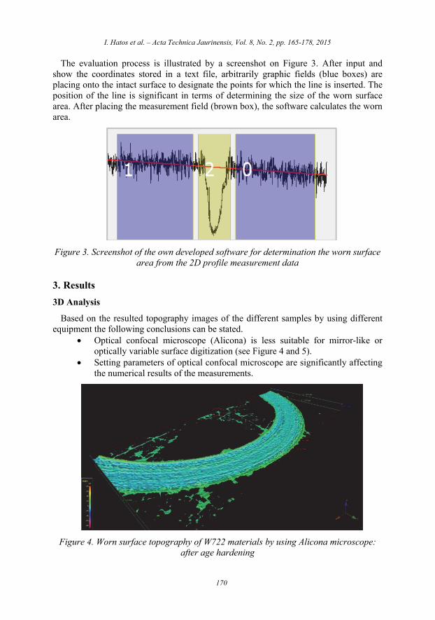
The evaluation process is illustrated by a screenshot on Figure 3. After input and show the coordinates stored in a text file, arbitrarily graphic fields (blue boxes) are placing onto the intact surface to designate the points for which the line is inserted. The position of the line is significant in terms of determining the size of the worn surface area. After placing the measurement field (brown box), the software calculates the worn area.
Figure 3. Screenshot of the own developed software for determination the worn surface area from the 2D profile measurement data
3. Results
3D Analysis
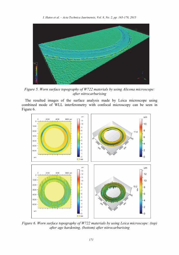
Based on the resulted topography images of the different samples by using different equipment the following conclusions can be stated.
Optical confocal microscope (Alicona) is less suitable for mirror-like or optically variable surface digitization (see Figure 4 and 5).
Setting parameters of optical confocal microscope are significantly affecting the numerical results of the measurements.
Figure 4. Worn surface topography of W722 materials by using Alicona microscope: after age hardening
I. Hatos et al. – Acta Technica Jaurinensis, Vol. 8, No. 2, pp. 165-178, 2015
171
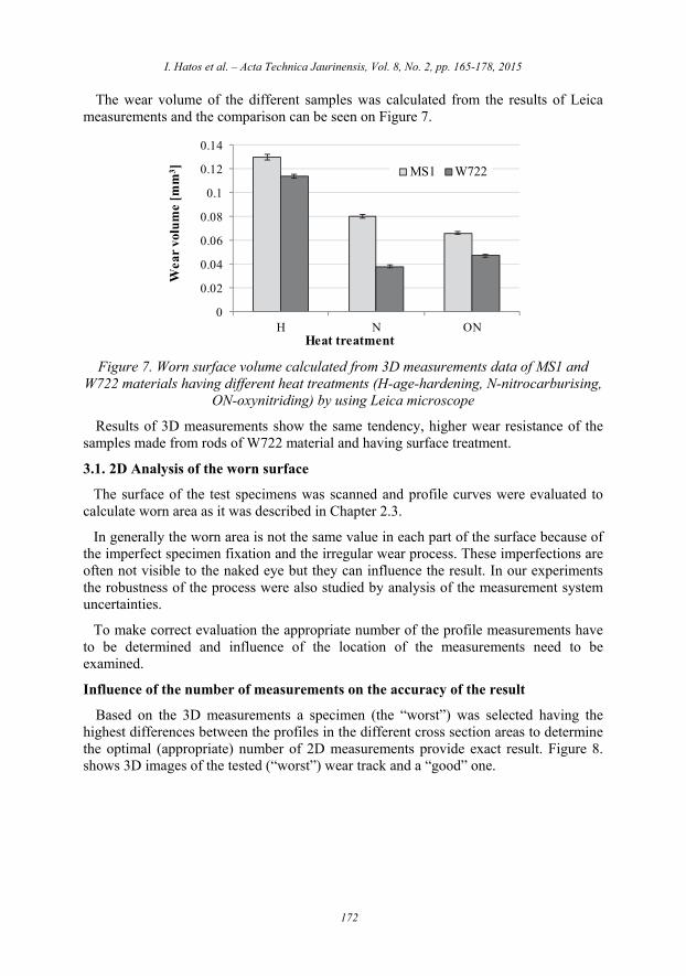
Figure 5. Worn surface topography of W722 materials by using Alicona microscope: after nitrocarburising
The resulted images of the surface analysis made by Leica microscope using combined mode of WLL interferometry with confocal microscopy can be seen in Figure 6.
Figure 6. Worn surface topography of W722 materials by using Leica microscope: (top) after age hardening, (bottom) after nitrocarburising
I. Hatos et al. – Acta Technica Jaurinensis, Vol. 8, No. 2, pp. 165-178, 2015
172
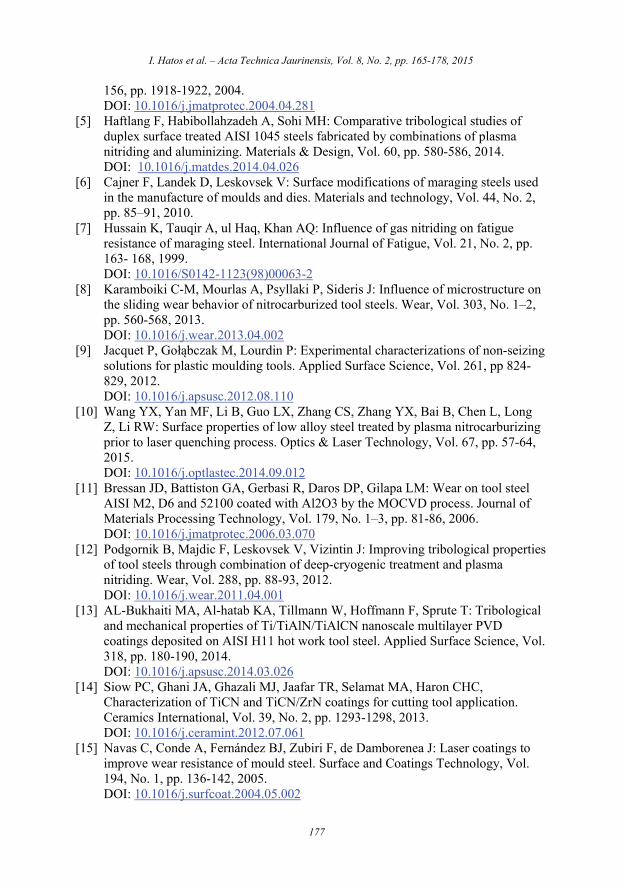
The wear volume of the different samples was calculated from the results of Leica measurements and the comparison can be seen on Figure 7.
Figure 7. Worn surface volume calculated from 3D measurements data of MS1 and W722 materials having different heat treatments (H-age-hardening, N-nitrocarburising,
ON-oxynitriding) by using Leica microscope
Results of 3D measurements show the same tendency, higher wear resistance of the samples made from rods of W722 material and having surface treatment.
3.1. 2D Analysis of the worn surface
The surface of the test specimens was scanned and profile curves were evaluated to calculate worn area as it was described in Chapter 2.3.
In generally the worn area is not the same value in each part of the surface because of the imperfect specimen fixation and the irregular wear process. These imperfections are often not visible to the naked eye but they can influence the result. In our experiments the robustness of the process were also studied by analysis of the measurement system uncertainties.
To make correct evaluation the appropriate number of the profile measurements have to be determined and influence of the location of the measurements need to be examined.
Influence of the number of measurements on the accuracy of the result
Based on the 3D measurements a specimen (the “worst”) was selected having the highest differences between the profiles in the different cross section areas to determine the optimal (appropriate) number of 2D measurements provide exact result. Figure 8. shows 3D images of the tested (“worst”) wear track and a “good” one.
0
0.02
0.04
0.06
0.08
0.1
0.12
0.14
H N ON
Wea
r vo
lum
e [m
m3]
Heat treatment
MS1 W722

I. Hatos et al. – Acta Technica Jaurinensis, Vol. 8, No. 2, pp. 165-178, 2015
173
Figure 8. 3D topography of the “worst” wear track used for the test series to determine the optimal cross section profile number for correct evaluation (left: MS1 after age hardening) and a “good” sample having only slight differences between the profiles
measured in different cross sections (right: W722 after age hardening)
On the wear track showed big differences in the different cross sections and obviously visible to the naked eye (see Figure 10) profile measurements were carried out along 4 diameter of the track (45° between the two neighbouring diameters), thus altogether 8 cross sections were scanned (No.1.-No.8.) (see Figure 9).
Figure 9. The locations of the profile measurements along the worn trace
Four type of measuring process was defined including different number of single results to determine the worn area and the standard deviation (accuracy the process) to characterize test specimen, as the followings:
8 data to compare: measurements in eight independent cross sections (No.1,2..8), characterizing the fault of choosing only one location to measure,
4 data to compare: average of measurements 2 cross sections along a diameter (No.1-2, No.3-4, No.5-6, No.7-8), characterizing the fault if taking measurement along one diameter.
2 data to compare: average of measurements 4 cross sections along 2 perpendicular diameters (No.1-4, No.5-6),
1 data: average of measurements 8 cross sections along 4 diameters 45° between the two neighbouring diameters (No.1-8)
The results of the measurements are presented in Figure 10.

I. Hatos et al. – Acta Technica Jaurinensis, Vol. 8, No. 2, pp. 165-178, 2015
174
Figure 10. Influence of the number of profile measurements on the accuracy of the resulted worn area (material: MS1 after age hardening). Worn area values calculated
as 8 single measurements or as an average of 2, 4 or 8 data.
In the first case having 8 independent data (white points) big differences can be seen between the resulted values. As expected one measurement is not enough for the precise characterization. If the measurement is carried out along one diameter and the worn area is calculated as an average of two data, more precise evaluation can be made (light grey). The four results (dark grey) are very close and having lower standard deviation. Doing profile measurements along two perpendicular diameters of the worn trace seems to be optimal for the precise characterization and more measurements (black point) cannot enhance the accuracy of the evaluation.
Results of worn surface analysis of DMLS and W722 materials
Worn traces of samples made by DMLS and from W722 were measured, and average worn areas were determined as average of measurements in four cross sections along two perpendicular diameters. The results are summarised in Figure 11.
Figure 11.Worn surface area calculated from 2D measurements data of MS1 and W722 materials having different heat treatments
As it is clearly seen the results are in good agreement with data of 3D measurements: W722 material has better wear resistance in each case and surface treatments have positive effect, by reducing significantly the worn area.
0.0040
0.0050
0.0060
0.0070
0.0080
0.0090
0.0100
0.0110
0.0120
0 1 2 3 4 5 6 7 8 9
Ave
rage
wor
n a
rea
[mm
2]
Number of measurements for calculation
single profiles
average of 2 profiles
average of 4 profiles
average of 8 profiles
0
0.002
0.004
0.006
0.008
0.01
0.012
H N ON
Wor
n a
rea
[mm
2]
Heat treatment
MS1 W722

I. Hatos et al. – Acta Technica Jaurinensis, Vol. 8, No. 2, pp. 165-178, 2015
175
Comparison the results of 2D and 3D analysis
When 2D measurements are carried out, the result is a distinct area of the worn trace or can be calculated as an average of some measurements, while in case of 3D measurements the whole volume of the worn trace can be measured. The surface and volume results can be compared if the results are related to a reference value. In our case the age hardened MS1 specimen was selected as reference value of both 2D and 3D measurements and each value was related to these values (average value), thus age hardened MS1 material has the maximal relative value of 1. Relative values of worn characteristic for both 2D and 3D measurements are shown in a common diagram (Figure 12).
Figure 12. Comparison of related values of 2D and 3D measurements (the data are related to the age hardened MS1 material in case of both test method)
It is clearly seen by the results that both 2D and 3D methods are suitable for the correct characterization of the wear resistance of the materials. Only a slight difference can be seen between the results calculated from the different test results.
The wear volume was calculated by using the 2D profile results (as average of measurements 4 cross sections along 2 perpendicular diameters) and a good correlation was found between the measured and calculated data (Figure 13).
Figure 13. Comparison of wear volume data of 3D measurements and calculated from
2D measurement results
0
0.1
0.2
0.3
0.4
0.5
0.6
0.7
0.8
0.9
1
MS1_H W722_H MS1_N W722_N MS1_ON W722_ON
2D a
nd 3
D r
esul
ts r
elat
ed t
o M
S1_
H
2D 3D
0
0.02
0.04
0.06
0.08
0.1
0.12
0.14
0.16
0.18
0.2
MS1_H MS1_N MS1_ON W722_H W722_N W722_ON
Wea
r vo
lum
e [m
m3 ]
measured (3D)
calculated (2D)

I. Hatos et al. – Acta Technica Jaurinensis, Vol. 8, No. 2, pp. 165-178, 2015
176
4. Conclusions
In our experiments one the other hand we focused on tribological characterization of maraging steels to compare the effectiveness of different heat treatments. Samples for the wear tests were produced by DMLS method from EOS MS1 material and from rod made of W722 tool steel with equivalent chemical composition. The samples were tested by ball-on-disc equipment after age-hardening, nitrocarburising and nitrocarburising with post oxidation.
The other aim of our experiments was to compare the reliability of the results derives from data of 2D and 3D measurements, and to determine the optimal number of measurements in case of the used 2D method.
Based on the results the followings can be concluded: Profile measurements along two perpendicular diameters of the wear track
ensure good accuracy in determination worn area to characterise the wear resistance of the surface.
In comparison the relative wear characteristics of 2D and 3D results of Leica measurements the same tendencies and very slight differences were found between the related values of the surface and volume measurements. Both of the evaluation methods can be used for precise characterisation and comparison of the wear resistance tested by ball-on-disc tribometer.
The wear volume determined by 3D measurements show good correlation with the results calculated from 2D measurement data.
Acknowledgement
This paper was supported by the János Bolyai Research Scholarship of the Hungarian Academy of Sciences. The research work presented in this paper was carried out as part of the TÁMOP-4.2.2.A-11/1/KONV-2012-0029 project in the framework of the New Széchenyi Plan. The realization of this project is supported by the European Union, and co-financed by the European Social Fund.
References
[1] Au KM, Yu KM, Chiu WK: Visibility-based conformal cooling channel generation for rapid tooling. Computer-Aided Design, Vol. 43, No. 4, pp. 356-373, 2011. DOI: 10.1016/j.cad.2011.01.001
[2] Nickels L: Channelling quality for moulded parts using fast manufacturing. Metal Powder Report, Vol. 64, No. 8, pp. 8-12, 2009. DOI: 10.1016/S0026-0657(09)70201-2
[3] Kumar S: Selective Laser Sintering/Melting. in Comprehensive Materials Processing, Editors: Hashmi S., Batalha G. F, Van Tyne C. J, Yilbas B, Elsevier, Oxford, pp. 93-134, 2014. DOI: 10.1016/B978-0-08-096532-1.01003-7
[4] Zeghni AE, Hashmi MSJ: The effect of coating and nitriding on the wear behaviour of tool steels. Journal of Materials Processing Technology, Vol. 155–
I. Hatos et al. – Acta Technica Jaurinensis, Vol. 8, No. 2, pp. 165-178, 2015
177
156, pp. 1918-1922, 2004. DOI: 10.1016/j.jmatprotec.2004.04.281
[5] Haftlang F, Habibollahzadeh A, Sohi MH: Comparative tribological studies of duplex surface treated AISI 1045 steels fabricated by combinations of plasma nitriding and aluminizing. Materials & Design, Vol. 60, pp. 580-586, 2014. DOI: 10.1016/j.matdes.2014.04.026
[6] Cajner F, Landek D, Leskovsek V: Surface modifications of maraging steels used in the manufacture of moulds and dies. Materials and technology, Vol. 44, No. 2, pp. 85–91, 2010.
[7] Hussain K, Tauqir A, ul Haq, Khan AQ: Influence of gas nitriding on fatigue resistance of maraging steel. International Journal of Fatigue, Vol. 21, No. 2, pp. 163- 168, 1999. DOI: 10.1016/S0142-1123(98)00063-2
[8] Karamboiki C-M, Mourlas A, Psyllaki P, Sideris J: Influence of microstructure on the sliding wear behavior of nitrocarburized tool steels. Wear, Vol. 303, No. 1–2, pp. 560-568, 2013. DOI: 10.1016/j.wear.2013.04.002
[9] Jacquet P, Gołąbczak M, Lourdin P: Experimental characterizations of non-seizing solutions for plastic moulding tools. Applied Surface Science, Vol. 261, pp 824-829, 2012. DOI: 10.1016/j.apsusc.2012.08.110
[10] Wang YX, Yan MF, Li B, Guo LX, Zhang CS, Zhang YX, Bai B, Chen L, Long Z, Li RW: Surface properties of low alloy steel treated by plasma nitrocarburizing prior to laser quenching process. Optics & Laser Technology, Vol. 67, pp. 57-64, 2015. DOI: 10.1016/j.optlastec.2014.09.012
[11] Bressan JD, Battiston GA, Gerbasi R, Daros DP, Gilapa LM: Wear on tool steel AISI M2, D6 and 52100 coated with Al2O3 by the MOCVD process. Journal of Materials Processing Technology, Vol. 179, No. 1–3, pp. 81-86, 2006. DOI: 10.1016/j.jmatprotec.2006.03.070
[12] Podgornik B, Majdic F, Leskovsek V, Vizintin J: Improving tribological properties of tool steels through combination of deep-cryogenic treatment and plasma nitriding. Wear, Vol. 288, pp. 88-93, 2012. DOI: 10.1016/j.wear.2011.04.001
[13] AL-Bukhaiti MA, Al-hatab KA, Tillmann W, Hoffmann F, Sprute T: Tribological and mechanical properties of Ti/TiAlN/TiAlCN nanoscale multilayer PVD coatings deposited on AISI H11 hot work tool steel. Applied Surface Science, Vol. 318, pp. 180-190, 2014. DOI: 10.1016/j.apsusc.2014.03.026
[14] Siow PC, Ghani JA, Ghazali MJ, Jaafar TR, Selamat MA, Haron CHC, Characterization of TiCN and TiCN/ZrN coatings for cutting tool application. Ceramics International, Vol. 39, No. 2, pp. 1293-1298, 2013. DOI: 10.1016/j.ceramint.2012.07.061
[15] Navas C, Conde A, Fernández BJ, Zubiri F, de Damborenea J: Laser coatings to improve wear resistance of mould steel. Surface and Coatings Technology, Vol. 194, No. 1, pp. 136-142, 2005. DOI: 10.1016/j.surfcoat.2004.05.002

I. Hatos et al. – Acta Technica Jaurinensis, Vol. 8, No. 2, pp. 165-178, 2015
178
[16] Fontalvo GA, Humer R, Mitterer C, Sammt K, Schemmel I: Microstructural aspects determining the adhesive wear of tool steels, Wear, Vol. 260, No. 9–10, pp. 1028-1034, 2006. DOI: 10.1016/j.wear.2005.07.001
[17] Karamboiki C-M, Mourlas A, Psyllaki P, Sideris J: Influence of microstructure on the sliding wear behavior of nitrocarburized tool steels. Wear, Vol. 303, No 1–2, pp. 560-56815, 2013. DOI: 10.1016/j.wear.2013.04.002
[18] Psyllaki PP, Jeandin M, Pantelis DI, Allouard M: Pin-on-disc testing of PE-CVD diamond-like carbon coatings on tool steel substrates. Surface and Coatings Technology, Vol. 130, No. 2–3, pp. 297-303, 2000. DOI: 10.1016/S0257-8972(00)00711-8