study of beam-beam interaction with a large piwinski … · study of beam-beam interaction with a...
TRANSCRIPT

Study of beam-beam interaction with a large Piwinski angle at LHC
K. Ohmi ∗
KEK, 1-1 Oho, Tsukuba, 305-0801, Japan
Abstract
Collision with a large Piwinski angle is one of the updatescenarios of LHC toward the luminosity 1035 cm−2s−1.The large Piwinski angle is realized by a small beta func-tion at the collision point and longer bunch length. The Pi-winski angle is increased from 0.6 to 2 in the scenario. Thebunch population is increased so as to keep the beam-beamparameter.
The beam-beam performance is degraded by crossingangle which induces additional nonlinear terms due to asymmetry breaking of the collision especially for the highbeam-beam parameter. Effect of crossing angle for thenominal LHC design and the large Piwinski angle schemeare studied.
INTRODUCTION
We discuss effects of crossing angle in LHC and its up-grade plans. Piwinski angle for horizontal crossing is de-fined by
φ =θσz
σx. (1)
where θ, σz and σx are a half crossing angle, bunch lengthand horizontal beam size, respectively. The nominal LHCis θ = 140 μrad, σz = 7 cm and σx = 17 μm, thus thePiwinski angle is φ = 0.6.
The crossing angle induces [7] various nonlinear terms,which degrade the luminosity performance. The large Pi-winski angle scheme φ = 2 expects linear luminosityincrease for the bunch population without increasing thebeam-beam parameter. We study the beam-beam perfor-mance for the crossing collision in the nominal design andupgrade options using computer simulations.
EFFECT OF CROSSING ANGLE
Lorentz transformation is used so that the two beamsmove completely opposite direction. Electro-magneticfield is formed in the perpendicular to the moving direc-tion, thus colliding beam experiences the electro-magneticfield in the perpendicular to the moving direction [1, 2, 3].This feature simplifies treatment of the beam-beam force.The schematic view is seen in Figure 1.
The Lorentz transformation from the laboratory frame tothe head-on frame (ML) is given for a half crossing angleθ by [3]
x∗ = tan θz +(
1 +p∗xp∗s
sin θ)x
Figure 1: Collision in the laboratory and head-on frame.Light blue and orange arrows display the electric field lineof the colliding bunches. Black arrow displays the travelingdirection of the bunches.
y∗ = y + sin θp∗yp∗sx
z∗ =z
cos θ− H∗
p∗ssin θx
p∗x =px − tan θH
cos θ(2)
p∗y =py
cos θp∗z = pz − tan θpx + tan2 θH,
where
H = (1 + pz) −√
(1 + pz)2 − p2x − p2
y
ps =√
(1 + pz)2 − p2x − p2
y.
A star designates a dynamical variable in the head-onframe. H∗ and p∗s are H(p∗) and ps(p∗), respectively.Note that the x∗ and y∗ axes are defined in the same di-rection for both beams, while the s∗ axis is defined in op-posite directions, since the two beams travel in oppositedirections.
The linear part of the transformation is expressed by amatrix
ML =
⎛⎜⎜⎜⎜⎜⎜⎝
1 0 0 0 tan θ 00 1/ cos θ 0 0 0 00 0 1 0 0 00 0 0 1/ cos θ 0 00 0 0 0 1/ cos θ 00 − tan θ 0 0 0 1
⎞⎟⎟⎟⎟⎟⎟⎠.
(3)These transformations, Eqs.(2) and (3), are not symplec-
tic. In fact, the determinant of the transfer matrixML is not1, but cos−3 θ. This is not a problem because the inversefactor of cos3 θ is applied by the inverse transformation.This is due to the fact that the Lorenz transformation isnot symplectic for the accelerator coordinate, because theHamiltonian is divided by a reference momentum. Need-less to say, the Lorentz transformation is symplectic for the

physical coordinate, thus the transformations, Eqs.(2) and(3), are symplectic in the physical coordinate. The adia-batic damping is the concept in the accelerator coordinate.This discussion can be applied to the nonlinear transforma-tion of Eq.(2) [4].
SIMULATION FOR NOMINAL LHC
We first evaluate luminosity for the nominal LHC us-ing weak-strong and strong-strong simulations. Crossingangle induces linear x − z coupling, with the result thatthe beam distribution diffuses and the luminosity degrades[4]. The diffusion rate strongly depends on the beam-beamparameter. For electron-positron colliders, the diffusionrate is faster than radiation damping rate > 10−4/turn forξ > 0.05. Here damping rate of LHC is the order of oneday 109 turns and the luminosity life time is expected 109
turns. Tolerable diffusion rate or luminosity decrement is10−9/turn. The simulations was carried out during ∼ 106
turns in this paper. The decrement of 10−3 should be caredto predict the luminosity life time of 109 turns.
Figure 2 shows evolution of the beam-size and luminos-ity given by the weak-strong and strong-strong simulationfor the nominal bunch population. Plot (a) depicts beamsize evolution given by the weak-strong and strong-strongsimulations. A bunch is sliced in 10 pieces along its lengthin the weak-strong simulation. Macro-particles of 104 wasused in the weak-strong simulation. The beam size of theweak beam is averaged in each 100 turns. No emittancegrowth nor luminosity degradation were seen in the weak-strong simulation.
Two dimensional model is used for the strong-strongsimulation to save the calculation time. This approxima-tion may give optimistic results. However an emittancegrowth is seen in the strong-strong simulation. The emit-tance growth is considered by numerical noise of macro-particle statistics. Macro-particles of 106 are used the sim-ulation. The statistical noise of collision offset (0.1%) canbe introduced collision by collision in the simulation [5].Needless to say, the weak-strong simulation is noise free.Plot (b) depicts luminosity evolution for the nominal, twiceand 4 times bunch populations. Luminosity degradationsare 10−9, 5× 10⁻⁹ and 3× 10⁻⁸ in one turn, respectively.If we believe this result, the bunch population is limited tothe nominal value by the beam-beam effect. Here we con-sider this degradation is due to the numerical noise again.More discussions for noises in macro-particle simulationsare seen in Ref.[6]. We use only the weak-strong simula-tion hereafter.
Figure 3 shows the luminosity degradation for 2×, 4×,6× and 8×more bunch populations than the nominal value.The red and green lines depict the evolution of the lumi-nosity zero or finite crossing angle. In the nominal bunchpopulation, there was no difference between zero and finitecrossing angle. The difference was visible for more than 6times population. Anyway, the nominal LHC is no problemfor finite crossing angle.
0.5
0.502
0.504
0.506
0.508
0 0.1 0.2 0.3 0.4 0.5 0.6 0.7 0.8 0.9 1
σ(μm
)
turn (x106)
strong-strongweak-strong
0.97
0.975
0.98
0.985
0.99
0.995
1
1.005
1.01
0 0.1 0.2 0.3 0.4 0.5 0.6 0.7 0.8
L/L 0
turn (x106)
Np2xNp4xNp
Figure 2: Beam size increment and luminosity decrementgiven by the strong-strong simulation.
0.9997
0.9998
0.9999
1
1.0001
1.0002
1.0003
0 0.2 0.4 0.6 0.8 1
L/L 0
turn (x106)
θ=0.15 mradθ=0 mard
0.9997
0.9998
0.9999
1
1.0001
1.0002
1.0003
0 0.2 0.4 0.6 0.8 1
L/L 0
turn (x106)
θ=0.15 mradθ=0 mrad
0.997
0.998
0.999
1
1.001
0 0.2 0.4 0.6 0.8 1
L/L 0
turn (x106)
θ=0.15 mradθ=0 mrad
0.993
0.994
0.995
0.996
0.997
0.998
0.999
1
1.001
0 0.2 0.4 0.6 0.8 1
L/L 0
turn (x106)
θ=0.15 mradθ=0 mrad
Figure 3: Luminosity degradation due to the crossing anglegiven by the weak-strong simulation. Plots (a)-(d) depictsfor 2×, 4×, 6× and 8× more bunch population than thenominal value, respectively.
LARGE PIWINSKI ANGLE OPTION
We study a large Piwinski angle option for LHC. Table1 [8] shows parameter list of the large Piwinski angle op-tions. The Piwinski angle φ = 2 is realized in the firstoption with long flat bunch, a half beta and 5 times bunchpopulation. The angle φ = 3 is realized in the second op-tion with a quarter low beta and 2 times bunch population.In this paper we study the first scheme (LPA1).
LHC has two collision points. Both of the two collisionpoints are designed so as horizontal-horizontal crossing inthe nominal design. Hybrid crossing, in which horizon-tal and vertical crossing[9] are adopted for the two inter-action points, can be considered for the upgrade plan. Thetune spread due to the nonlinear beam-beam interaction is

narrower for the hybrid crossing than the nominal cross-ing. The horizontal crossing induces the nonlinear termsxy2 while vertical crossing induces skew terms x2y. Thismeans the hybrid crossing induces more resonances thanthe nominal crossing. It is very difficult which is better thetwo cases, less resonance with wider tune spread, or moreresonances with narrower resonances. The answer dependson the case by case, operating point, beam-beam parameterand so on. Simulation only gives the answer.
The nominal crossing induces the same nonlinear inter-actions at the two interaction point. This means some non-linear terms can be cancelled depending on the betatronphase difference. In the hybrid crossing, some terms canbe cancelled but terms with different symmetry (parity) cannot be cancelled.
Table 1: Basic parameters of LHC nominal and large Pi-winski angle option. ∗ The bunch length is total lengthwith a flat longitudinal distribution.
variable nominal LPA-1 LPA-2circumference (m) 26,658beam energy (TeV) 7bunch population (1011) 1.15 4.9 2.5half crossing angle (mrad) 0.14 0.19 -beta function at IP (m) 0.55 0.25 0.14emittance (m) 5.07 × 10⁻¹⁰
beam-beam tune shift 0.0033bunch length (cm) 7 41∗ 7.5synchrotron tune, νs 0.0019betatron tune, νx(y) 63.31/59.32revolution frequency 109/dayPiwinski angle φ 0.4 2 3luminosity (cm−2s−1) 1 10
Simulation for the nominal and hybrid crossings
The weak-strong simulation was executed to study thelarge Piwinski angle scheme. The number of the longitu-dinal slices are increased for proportional to the Piwinskiangle. We show examples of the nominal and hybrid cross-ings. It should be emphasized that the results depend on thebetatron phase difference between two IP. Here the phasedifference is chosen to be Δψ = 0.2 × 2π for both of x-yplane. The parasitic interactions are included in the simu-lation.
Figure 4 shows the simulation results for Np = 4.9 ×10¹¹ with including 7 parasitic collisions both side of up-stream and down stream of the collision point. Plots (a),(b) and (c) depict the evolution of luminosity and beamsize, and beam particle distribution in x-y plane after 106
revolutions, respectively. Red and green lines are turn byturn beam size and its average during 100 turns. Lumi-nosity does not change, while the beam size fluctuates for
the revolutions. It is seen that some particles have a largeamplitude in the final distribution (c).
0.99
0.995
1
1.005
1.01
0 0.05 0.1 0.15 0.2 0.25 0.3 0.35 0.4
L/L 0
turn (x106)
0.98
0.99
1
1.01
1.02
1.03
1.04
1.05
0 0.05 0.1 0.15 0.2 0.25 0.3 0.35 0.4
σ/σ 0
turn (x106)
-0.5
-0.4
-0.3
-0.2
-0.1
0
0.1
0.2
0.3
-0.3 -0.2 -0.1 0 0.1 0.2
y (m
m)
x (mm)
Figure 4: Np = 4.9× 10¹¹ Evolution of (a) luminosity and(b)beam size. (c) Beam particle distribution in x-y planeafter 106 revolutions.
A higher bunch population, Np = 6 × 10¹¹ was triedto make clear the luminosity degradation and emittancegrowth. Figure 5 shows the simulation results for Np =6 × 10¹¹ with including 7 parasitic collisions each side.Again the luminosity does not degrade, but beam size in-creases faster than that of the nominal population, Np =4.9 × 10¹¹. More particles have large amplitudes in thefinal distributions.
0.99
0.995
1
1.005
1.01
0 0.05 0.1 0.15 0.2 0.25 0.3 0.35 0.4
L/L 0
turn (x106)
0.9
1
1.1
1.2
1.3
1.4
1.5
0 0.05 0.1 0.15 0.2 0.25 0.3 0.35 0.4
σ/σ 0
turn (x106)
-0.8
-0.6
-0.4
-0.2
0
0.2
0.4
0.6
0.8
-1.2 -1 -0.8 -0.6 -0.4 -0.2 0 0.2 0.4 0.6 0.8
y (m
m)
x (mm)
Figure 5: Np = 6 × 10¹¹ Evolution of (a) luminosity and(b)beam size. (c) Beam particle distribution in x-y planeafter 106 revolutions.
We next cut off the parasitic interactions to understandwhy particles have large amplitudes. Figure 6 shows thesimulation results forNp = 6× 10¹¹ without parasitic col-lisions.
The same simulation was carried out for the nominalcollision scheme, horizontal-horizontal. Emittance growthand luminosity degradation were not seen in the nominalcollision. We would like to say the tune spread is notuniversal parameter to characterize the emittance growthand/or beam-beam performance, and we do not conclude
0.99
0.995
1
1.005
1.01
0 0.05 0.1 0.15 0.2 0.25 0.3 0.35 0.4
L/L 0
turn (x106)
0.98
0.985
0.99
0.995
1
1.005
1.01
1.015
1.02
0 0.05 0.1 0.15 0.2 0.25 0.3 0.35 0.4
σ/σ 0
turn (x106)
Figure 6: Np = 6 × 10¹¹ Evolution of (a) luminosity and(b)beam size. (c) Beam particle distribution in x-y planeafter 106 revolutions.
that the nominal collision scheme is better than the hybridscheme in this example.
Taylor map analysis for the nominal and hybridcrossings
Nonlinear terms in one turn map depend on the colli-sion scheme; the nominal or hybrid crossing, or betatronphase difference between the two interaction points. Thebeam-beam interaction can be expanded by Taylor polyno-mial for the dynamic variables. The one turn map includingtwo interaction points and two linear arcs is represented byTaylor polynomial. The one turn map characterizes reso-nance behaviors of the beam particles. For example, xnym
term in the map, exp(−a : xnym :), drives resonances ofnνx ± mνy . Details of the analysis is seen in Ref. [7]We discuss nonlinear terms up to 4-th order in this paper.Higher order terms may be important for proton rings with-out radiation damping. Further studies will be done else-where.
Figure 7 shows the coefficient of x4 term of the beam-beam interaction as a function of the betatron phase differ-ence between the two interaction points. The coefficientfor the nominal crossing is small than that for hybrid cross-ing. This means the x4 term is weakened by long bunchcollision in the horizontal plane, perhaps. The coefficienthas peaks for the phase difference of 0.3 and 0.8. The to-tal tune is (νx, νy) = (0.31, 0.32). The phase difference isanother arc is 0.5 or 1 at the peaks, respectively.
0
5e+06
1e+07
1.5e+07
2e+07
2.5e+07
3e+07
0 0.1 0.2 0.3 0.4 0.5 0.6 0.7 0.8 0.9 1
C(4
00)
dφ/2π
HH,400000HV,400000
Figure 7: Coefficient of x4 term for the betatron phase dif-ference between the two interaction points. Red (HH) andgreen (HV) lines are for the horizontal-horizontal crossingadn horizontal-vertical crossing, respectively.
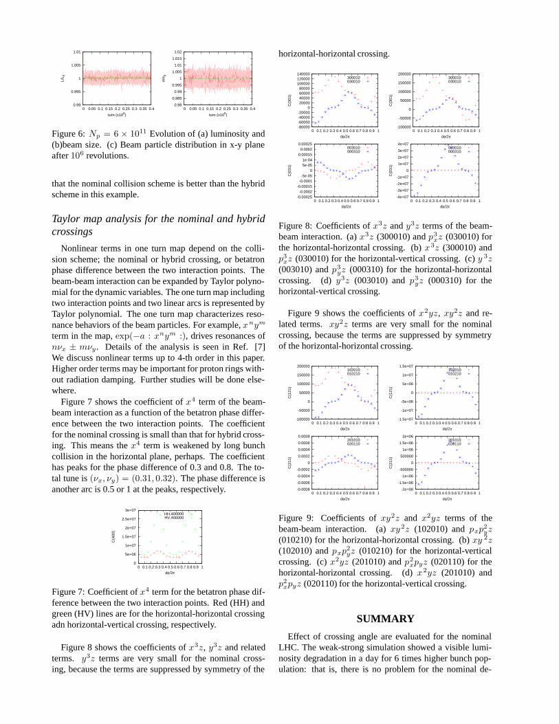
Figure 8 shows the coefficients of x3z, y3z and relatedterms. y3z terms are very small for the nominal cross-ing, because the terms are suppressed by symmetry of the
horizontal-horizontal crossing.
-80000-60000-40000-20000
0 20000 40000 60000 80000
100000 120000 140000
0 0.1 0.2 0.3 0.4 0.5 0.6 0.7 0.8 0.9 1
C(3
01)
dφ/2π
300010030010
-100000
-50000
0
50000
100000
150000
200000
0 0.1 0.2 0.3 0.4 0.5 0.6 0.7 0.8 0.9 1
C(3
01)
dφ/2π
300010030010
-0.00025-0.0002
-0.00015-0.0001-5e-05
0 5e-05 1e-04
0.00015 0.0002
0.00025
0 0.1 0.2 0.3 0.4 0.5 0.6 0.7 0.8 0.9 1
C(0
31)
dφ/2π
003010000310
-4e+07
-3e+07
-2e+07
-1e+07
0
1e+07
2e+07
3e+07
4e+07
0 0.1 0.2 0.3 0.4 0.5 0.6 0.7 0.8 0.9 1
C(0
31)
dφ/2π
003010000310
Figure 8: Coefficients of x3z and y3z terms of the beam-beam interaction. (a) x3z (300010) and p3
xz (030010) forthe horizontal-horizontal crossing. (b) x3z (300010) andp3
xz (030010) for the horizontal-vertical crossing. (c) y 3z(003010) and p3
yz (000310) for the horizontal-horizontalcrossing. (d) y3z (003010) and p3
yz (000310) for thehorizontal-vertical crossing.
Figure 9 shows the coefficients of x2yz, xy2z and re-lated terms. xy2z terms are very small for the nominalcrossing, because the terms are suppressed by symmetryof the horizontal-horizontal crossing.
-100000
-50000
0
50000
100000
150000
200000
0 0.1 0.2 0.3 0.4 0.5 0.6 0.7 0.8 0.9 1
C(1
21)
dφ/2π
102010010210
-1.5e+07
-1e+07
-5e+06
0
5e+06
1e+07
1.5e+07
0 0.1 0.2 0.3 0.4 0.5 0.6 0.7 0.8 0.9 1
C(1
21)
dφ/2π
102010010210
-0.0008
-0.0006
-0.0004
-0.0002
0
0.0002
0.0004
0.0006
0.0008
0 0.1 0.2 0.3 0.4 0.5 0.6 0.7 0.8 0.9 1
C(2
11)
dφ/2π
201010020110
-2e+06
-1.5e+06
-1e+06
-500000
0
500000
1e+06
1.5e+06
2e+06
0 0.1 0.2 0.3 0.4 0.5 0.6 0.7 0.8 0.9 1
C(2
11)
dφ/2π
201010020110
Figure 9: Coefficients of xy2z and x2yz terms of thebeam-beam interaction. (a) xy2z (102010) and pxp
2yz
(010210) for the horizontal-horizontal crossing. (b) xy 2z(102010) and pxp
2yz (010210) for the horizontal-vertical
crossing. (c) x2yz (201010) and p2xpyz (020110) for the
horizontal-horizontal crossing. (d) x2yz (201010) andp2
xpyz (020110) for the horizontal-vertical crossing.
SUMMARY
Effect of crossing angle are evaluated for the nominalLHC. The weak-strong simulation showed a visible lumi-nosity degradation in a day for 6 times higher bunch pop-ulation: that is, there is no problem for the nominal de-

sign. The strong-strong simulation gave luminosity degra-dation stronger than that of the weak-strong simulation.This degradation is considered due to numerical noise ofmacro-particle statistics at present.
High Piwinski angle scheme with a half beta and twicelonger bunch length was investigated. The simulation in-cluded 7 parasitic interactions both of upstream and down-stream of the collision point. Two type of collision schemefor two collision points, the nominal horizontal-horizontalcrossing and the hybrid horizontal-vertical crossing, wasstudied. An example for each scheme was investigated withthe weak-strong simulation. The hybrid crossing gave ahalo formation due to the parasitic interactions in this ex-ample. We should not conclude that the nominal collisionscheme is better than the hybrid scheme in this example.
Preliminary results for Taylor map analysis of the beam-beam interactions were presented. Nonlinear terms de-pending on the symmetry (parity) of the colliding systemappear in the map. The nominal crossing gives a wide tunespread but less resonance term, while the hybrid crossinggives a narrow tune spread but more resonance terms. Itis difficult to say simply which is better; depending on theoperating point, betatron phase difference between the twointeraction points.
ACKNOWLEDGMENMT
The author thanks to K. Takayama and F. Zimmermannfor fruitful discussions.
REFERENCES
[1] J. Augustin, Orsay Report, No 36-69 (1969).
[2] K. Oide and K. Yokoya, Phys. Rev. A40, 315 (1989).
[3] K. Hirata, Phys. Rev. Lett. 74, 2228 (1995).
[4] K. Ohmi et al., Phys. Rev. ST-AB 7,104401 (2004).
[5] K. Ohmi et al., Proceedings of PAC07 (2007).
[6] K. Ohmi, Proceedings of ECLOUD07, KEK proceedings2007-10, 189 (2007)
[7] K. Ohmi et al., Proceedings of PAC07 (2007).
[8] F. Zimmermann, Proceedings of PAC07 (2007).
[9] K. Takayama et al., Phys. Rev. Lett. 88, 144801 (2002).
[10] F. Ruggiero and F. Zimmermann, Phys. Rev. ST-AB 5,061001 (2002).