study of mechanical properties of … kumar.pdf · coconut coir fibre and shell particle reinforced...
TRANSCRIPT
International Journal of Advances in Engineering Research http://www.ijaer.com
(IJAER) 2012, Vol. No. 4, Issue No. II, August ISSN: 2231-5152
39
International Journal of Advances in Engineering Research
STUDY OF MECHANICAL PROPERTIES OF COCONUT SHELL
PARTICLE AND COIR FIBRE REINFORCED EPOXY
COMPOSITE
Shiv Kumar1, Dr.B.Kumar
2
1 Ph.D Research Scholar CMJ University Shillong, Meghalaya India
2Director RD Engineering College, Ghaziabad
ABSTRACT
Coconut coir fibre and shell particle reinforced epoxy based composite has proven a very promising material
for structural application where wood and plastics were used. It has well mechanical property. Following
has been concluded more specifically for this coir and particle reinforced composite. Density of this
composite developed using only shell particle is low and order of 1.171g/cm3 for 35wt% of shell particle
changes from 28% to 35%. Here it is possible to comment that density decreases with increase of wt% of
particle. Density increases with addition of shell particle in case of coir and particle composite. Here fibre
reduces density. The water absorption capacity was found to be maximum for 33 to 35 wt % of coconut shell
particle for composite of particle only. Water absorption increases with increase of coir wt% in coir and
particle composite. Density of this does not increase appreciably with increase of particle content with coir.
This does not increase up to mark for both only particle based and coir & particle Composites. Uniform
dispersion of coconut shell particle and coir is found. So, mixing and adhesion among particles and coir
fibre is proper. Disorder is negligible.
Tensile properties: Ultimate strength equal to 30 MPa and modulus of elasticity equal to 856 MPa is
achieved for 20%wt shell particle reinforced composite. Ultimate strength of 48 MPa and modulus of
elasticity of 920 MPa are achieved for 18%wt shell particle & 2%wt coir fibre and 17%wt shell particle &
3%wt coir fibre reinforced composite respectively. Elasticity decreases with increase of coir and ultimate
strength decreases with increases with particle wt%. Ultimate strength and modulus of elasticity increase
with addition of coir. Compressive Properties: Maximum ultimate strength and maximum modulus of
elasticity is 88 MPa and 698 MPa for 30%wt particle reinforcement only. Maximum ultimate strength and
maximum modulus of elasticity is 78 MPa and 658 MPa for 28%wt particle with 2%wt coir fibre
reinforcement. So, compressive reduces with coir fibre. Flexural strength of 63.45 MPa is measured for
35%wt shell particle reinforcement. This strength decreases with the addition of coir fibre. Fracture
toughness decreases with increase of wt% of particle for only shell particle reinforced composite. It
increases minutely with increase of coir wt%. Rockwell hardness number increases with increase of wt% of
coconut shell particle and reduces with increase of coir fibre content. Its value maximum on 30%wt of
reinforcement with 2%wt of coir fibre.
Keywords: Coconut Shell Particles; Mechanical Properties; Composite; Morphology; coir fibre.
INTRODUCTION
India endowed with an abundant availability of natural fiber such as Jute, Coir, Sisal,Pineapple,
Ramie, Bamboo, Banana, Bagasse etc. has focused on the development of natural fiber composites
International Journal of Advances in Engineering Research http://www.ijaer.com
(IJAER) 2012, Vol. No. 4, Issue No. II, August ISSN: 2231-5152
40
International Journal of Advances in Engineering Research
primarily to explore value-added application avenues. Such natural fiber composites are well suited
as wood substitutes in the housing and construction sector. The development of natural fiber
composites in India is based on two pronged strategy of preventing depletion of forest resources as
well as ensuring good economic returns for the cultivation of natural fibers. Natural fillers and
fibers reinforced thermoplastic composite have successfully proven their high qualities in various
fields of technical application. Over past two decades, natural fibers have received considerable
attention as a substitute for synthetic fiber reinforcements in plastics. As replacements for
conventional synthetic fibers like aramid and glass fibers are increasingly used for reinforcement in
the thermoplastic due to their
low density,
good thermal insulation and mechanical properties,
reduced tool wear,
Unlimited availability, low price, and problem free disposal.
Natural fibers offer economical and environmental advantages over traditional inorganic
reinforcements and fillers. As a result of these advantages, natural fiber reinforced thermoplastic
composite are gaining popularity in automotive components. They are used as a replacement for
glass fiber in automotive components. They are used as trim parts in dashboards, door panels, parcel
shelves, seat cushions, and backrest and cabin linings. Several types of natural fibers such as kenaf,
jute , sisal, flax, and hemp were studied as reinforcement for thermoplastic such as
polypropylene(PP) and polyethylene. Among natural fibers, the coir fiber has remarkable interest in
the automotive industry wing to its hard-wearing quality and high hardness(not fradile like glass
fiber), good acoustic distance, moth-proof, not toxic, resistant to microbial and fungi degradation,
and not easily combustible. The coir fibers are also more resistant to moisture than other natural
fibers and withstand heat and salt water. Epoxy resins (ER) are one of the most important classes of
thermosetting polymers which are widely used as matrices for fiber-reinforced composite materials
and as structural adhesives. They are amorphous, highly cross linked polymers and this structure
results in these materials possessing various desirable properties such as high tensile strength and
modulus, uncomplicated processing, good thermal and chemical resistance, and dimensional
stability. However, it leads to low toughness and poor crack resistance, which should be upgraded
before they can be considered many end-use applications. One of the most successful methods of
improving the toughness of epoxy resin is to incorporate a second phase of dispersed rubbery
particles into the cross linked polymer. Because the addition of rubbery materials to epoxy resins
has been shown to lower their glass transition temperature (Tg) and thermal and oxidative stability,
high performance thermoplastic have been employed to toughen epoxy resin in recent years.
Coconut fruit is very useful for our life. It not only gives us fruit to eat but left out of fruit is very
useful for developing natural composites. Coconut shell is one of the most important natural fillers
produced in tropical countries like Malaysia, Indonesia, Thailand, and Srilanka. Many works have
been devoted to use of other natural fillers in composite in recent past and coconut shell filler and
husk fiber are potential candidates for the development of new composites because of their high
strength and modulus properties. The objective of this work is to study the mechanical behavior of
epoxy composite based on coconut husk fiber and shell filler particles. Over the last thirty years

International Journal of Advances in Engineering Research http://www.ijaer.com
(IJAER) 2012, Vol. No. 4, Issue No. II, August ISSN: 2231-5152
41
International Journal of Advances in Engineering Research
composite materials, plastics and ceramics have been the dominant emerging materials. The volume
and number of applications of composite materials have grown steadily, penetrating and conquering
new markets relentlessly. Modern composite materials constitute a significant proportion of the
engineered materials market ranging from everyday products to sophisticated niche applications.
While composites have already proven their worth as weight-saving materials, the current challenge
is to make them cost effective. The efforts to produce economically attractive composite
components have resulted in several innovative manufacturing techniques currently being used in
the composites industry. It is obvious, especially for composites, that the improvement in
manufacturing technology alone is not enough to overcome the cost hurdle. It is essential that there
be an integrated effort in design, material, process, tooling, quality assurance, manufacturing, and
even program management for composites to become competitive with metals.
The most widely used meaning is the following one, which has been stated by Jartiz (1965)
“Composites are multifunctional material systems that provide characteristics not obtainable from
any discrete material. They are cohesive structures made by physically combining two or more
compatible materials, different in composition and characteristics and sometimes in form”. The
weakness of this definition resided in the fact that it allows one to classify among the composites
any mixture of materials without indicating either its specificity or the laws which should given it
which distinguishes it from other very banal, meaningless mixtures.
Kelly (1967) very clearly stresses that the composites should not be regarded simple as a
combination of two materials. In the broader significance; the combination has its own distinctive
properties. In terms of strength to resistance to heat or some other desirable quality, it is better than
either of the components alone or radically different from either of them.
Beghezan(1966) defines as “The composites are compound materials which differ from alloys by
the fact that the individual components retain their characteristics but are so incorporated into the
composite as to take advantage only of their attributes and not of their short comings”, in order to
obtain improved materials.
Van Suchetclan (1972) explains composite materials as heterogeneous materials consisting of two
or more solid phases, which are in intimate contact with each other on a microscopic scale. They
can be also considered as homogeneous materials on a microscopic scale in the sense that any
portion of it will have the same physical property.
OBJECTIVE OF THE PRESENT INVESTIGATION
Objective of the present investigation is to develop a natural composite material containing
different percentage of coconut powder and coconut fiber in an epoxy resin matrix.
To study the microscopic structure and dispersion of filler material by scanning electron
microscopy analysis and to established structure properties correlation, if any.
To determine the mechanical properties of composite material like hardness, tensile strength,
compressive strength, impact strength, etc.
International Journal of Advances in Engineering Research http://www.ijaer.com
(IJAER) 2012, Vol. No. 4, Issue No. II, August ISSN: 2231-5152
42
International Journal of Advances in Engineering Research
APPROACH
There are mainly three major areas used in the present investigation i.e. material science, material
testing & microscopic investigation. Material science & testing is used to developed the composite
material and determine the mechanical properties such as tensile strength, compressive strength,
hardness, impact strength, dimensional stability and water absorption etc. Microscopic
investigation is used to determine the microstructure of the developed composite material. It is also
used to see dispersion and interaction of the filler material within the matrix.
COMPOSITE PREPARATION & METHODOLOGY
Its deals with the preparation of material and preparation of samples for number of tests required for
properties. Following are the methods used for mechanical properties and others.
Material, Matrix Material, Epoxy Resin
Epoxy resin is widely used in industrial application because of their high strength and mechanical
adhesiveness characteristic. Brush Bond makes epoxy resin SY-12(319) is a liquid solvent free
epoxy resin. It has versatile applications in technical and industrial applications. Curing takes place
at room temperature and atmospheric pressure after addition of hardener. Cure shrinkage is
generally very less and may be still further reduced by the addition of fillers. The resin can be
coloured easily. Fully cured mixture has excellent mechanical, thermal properties and atmospheric
attack. The castings have good ageing characteristics. It is odourless, tasteless and completely non-
toxic. Resin can be stored for at least a year if they are stored under cool, dry conditions in the
original containers. It is also good solvent and has good chemical resistance over a wide range of
temperature. In the present investigation SY-12(319) purchased from M/s RESINOVA CHEMIE
Limited, Kanpur India has been used as matrix material. The epoxy used is colourless, odourless
and completely nontoxic.
Hardener
Hardener SY31(B) is a yellowish-green liquid. Hardener SY31(B) purchased from M/s
RESINOVA CHEMIE limited, Kanpur, India has been used as curing agent. In the present
investigation 8 % wt/wt has been used in all material developed. The weight percentage of hardener
used in the present investigation is as per recommendation of Singh V.K. (2002), figure 1.1.
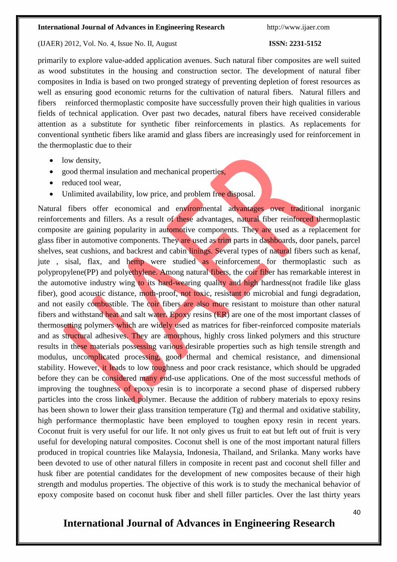
Reinforcing Element:
Coconut shell is used as reinforcing material for present investigation.
Coconut shell particle and its preparation:
Shells were collected and crushed in to small pieces by manual hammering
the shell then it was fed into crushing machine to convert it into powder form. This powder was
dried to remove moisture.
International Journal of Advances in Engineering Research http://www.ijaer.com
(IJAER) 2012, Vol. No. 4, Issue No. II, August ISSN: 2231-5152
43
International Journal of Advances in Engineering Research
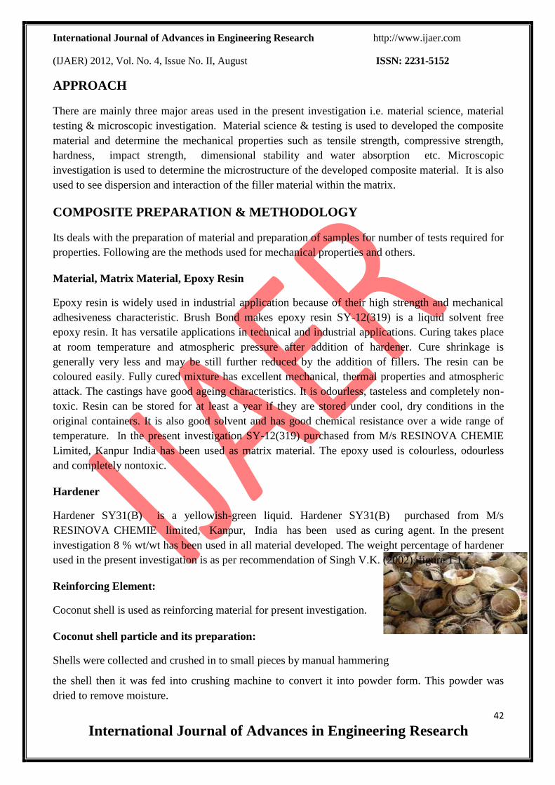
Fig.1.1 Coconut shell
Coconut fiber and its preparation:
Coconut fruit is covered inside coconut coir fiber. Fibers are very long and have good tensile
properties. It is assumed that this fiber covering gives damping strength to the coconut fruit for
protecting while falling from height.
Fig.1.2 Coconut shell particle
Fibers used were collected and milled to get fine form of coir fiber.
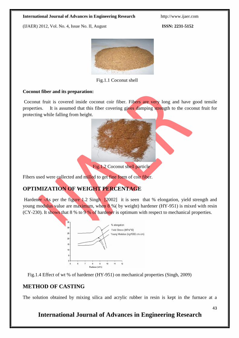
OPTIMIZATION OF WEIGHT PERCENTAGE
Hardener -As per the figure 1.2 Singh [2002] it is seen that % elongation, yield strength and
young modulus value are maximum, when 8 %( by weight) hardener (HY-951) is mixed with resin
(CY-230). It shows that 8 % to 9 % of hardener is optimum with respect to mechanical properties.
Fig.1.4 Effect of wt % of hardener (HY-951) on mechanical properties (Singh, 2009)
METHOD OF CASTING
The solution obtained by mixing silica and acrylic rubber in resin is kept in the furnace at a
International Journal of Advances in Engineering Research http://www.ijaer.com
(IJAER) 2012, Vol. No. 4, Issue No. II, August ISSN: 2231-5152
44
International Journal of Advances in Engineering Research
temperature of 90 ± 10 °C for two hours as per the recommendation of Singh V.K., 2003. The
electric furnace (Temperature Range 0-6000C) used for this purpose. At each interval of 30 minutes
the solution have been taken out from the furnace and remixed by mechanical stirrer at high speed.
After two hours the whole solution is taken out and allowed to cool to a temperature of 45°C. When
a temperature of 45°C has been attained the hardener HY-951 is mixed immediately. Due to
addition of hardener high viscous solution has been obtained which is again mixed mechanically by
high speed mechanical stirrer. The viscous solution so obtained is poured in to different moulds for
sample preparation for tensile, compression, wear and impact testing.
METHOD OF SPECIMEN PREPARATION
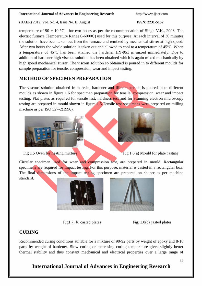
The viscous solution obtained from resin, hardener and filler materials is poured in to different
moulds as shown in figure 1.6 for specimen preparation for tensile, compression, wear and impact
testing. Flat plates as required for tensile test, hardness test and for scanning electron microscopy
testing are prepared in mould shown in figure 1.5.Tensile test specimens were prepared on milling
machine as per ISO 527-2(1996).
Fig.1.5 Oven for heating mixture Fig.1.6(a) Mould for plate casting
Circular specimen used for wear and compression test, are prepared in mould. Rectangular
specimens are required for Impact testing. For this purpose, material is casted in a rectangular box.
The final dimensions of the impact testing specimen are prepared on shaper as per machine
standard.
Fig1.7 (b) casted plates Fig. 1.8(c) casted plates
CURING
Recommended curing conditions suitable for a mixture of 90-92 parts by weight of epoxy and 8-10
parts by weight of hardener. Slow curing or increasing curing temperature gives slightly better
thermal stability and thus constant mechanical and electrical properties over a large range of
International Journal of Advances in Engineering Research http://www.ijaer.com
(IJAER) 2012, Vol. No. 4, Issue No. II, August ISSN: 2231-5152
45
International Journal of Advances in Engineering Research
temperatures.
Table 1.1: Curing temperature and time for epoxy with hardener material
TESTS PROCEDURE
Though there are number of mechanical tests, which are necessary to determine the suitability of a
metal, the following important tests have been performed in the present investigation.
1. Tensile test at different strain rate of 0.01, 0.1, 1.0, 10.0 and 100.0 mm/sec.
2. Compression test at different strain rate of 0.01, 0.1, 1.0, and 10.0 mm/min.
3. Hardness test
4. Bending strength test
5. Fracture toughness test
Different specimens for tensile, compression testing, fracture and hardness testing were made as per
ISO standard and as per directed by different testing machine.
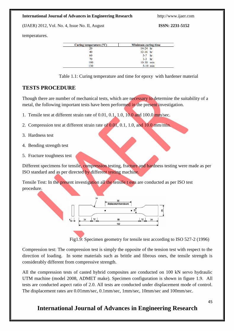
Tensile Test: In the present investigation all the tensile t ests are conducted as per ISO test
procedure.
Fig1.9: Specimen geometry for tensile test according to ISO 527-2 (1996)
Compression test: The compression test is simply the opposite of the tension test with respect to the
direction of loading. In some materials such as brittle and fibrous ones, the tensile strength is
considerably different from compressive strength.
All the compression tests of casted hybrid composites are conducted on 100 kN servo hydraulic
UTM machine (model 2008, ADMET make). Specimen configuration is shown in figure 1.9. All
tests are conducted aspect ratio of 2.0. All tests are conducted under displacement mode of control.
The displacement rates are 0.01mm/sec, 0.1mm/sec, 1mm/sec, 10mm/sec and 100mm/sec.
International Journal of Advances in Engineering Research http://www.ijaer.com
(IJAER) 2012, Vol. No. 4, Issue No. II, August ISSN: 2231-5152
46
International Journal of Advances in Engineering Research
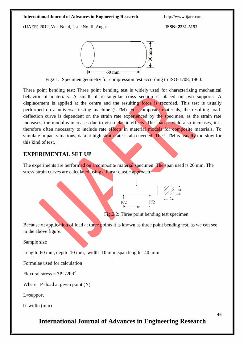
Fig2.1: Specimen geometry for compression test according to ISO-1708, 1960.
Three point bending test: Three point bending test is widely used for characterizing mechanical
behavior of materials. A small of rectangular cross section is placed on two supports. A
displacement is applied at the centre and the resulting force is recorded. This test is usually
performed on a universal testing machine (UTM). For composite materials, the resulting load-
deflection curve is dependent on the strain rate experienced by the specimen, as the strain rate
increases, the modulus increases due to visco elastic effects. The load at yield also increases, it is
therefore often necessary to include rate effects in material models for composite materials. To
simulate impact situations, data at high strain rate is also needed. The UTM is usually too slow for
this kind of test.
EXPERIMENTAL SET UP
The experiments are performed on a composite material specimen. The span used is 20 mm. The
stress-strain curves are calculated using a linear elastic approach.
Fig.2.2: Three point bending test specimen
Because of application of load at three points it is known as three point bending test, as we can see
in the above figure.
Sample size
Length=60 mm, depth=10 mm, width=10 mm ,span length= 40 mm
Formulae used for calculation
Flexural stress = 3PL/2bd2
Where P=load at given point (N)
L=support
b=width (mm)
International Journal of Advances in Engineering Research http://www.ijaer.com
(IJAER) 2012, Vol. No. 4, Issue No. II, August ISSN: 2231-5152
47
International Journal of Advances in Engineering Research
d=depth (mm)
Rockwell hardness test:
The Rockwell Hardness test also uses a machine to apply a specific load and then measure the depth
of the resulting impression. The indenter may either be a steel ball of some specified diameter or a
spherical diamond-tipped cone of 120° angle and 0.2 mm tip radius, called a brale. A minor load of
10 kgf is first applied, which causes a small initial penetration to seat the indenter and remove the
effects of any surface irregularities. T hen, the dial is set to zero and the major load is applied. Upon
removal of the major load, the depth reading is taken while the minor load is still on. The hardness
number may then be read directly from the scale. The indenter and the test load used determine the
hardness scale that is used (A, B, C, etc). For soft materials such as copper alloys, soft steel, and
aluminum alloys a 1/16" diameter steel ball is used with a 10 kgf load and the hardness is read on
the "B" scale. In testing harder materials, hard cast iron and many steel alloys, a 120 degrees
diamond cone is used with up to a 15 kgf load and the hardness is read on the "C" scale. There are
several Rockwell scales other than the "B" & "C" scales, (which are called the common scales). A
properly reported Rockwell value will have the hardness number followed by "HR" (Hardness
Rockwell) and the scale letter. For example, 50 HRB indicates that the material has a hardness
reading of 50 on the B scale.
A- Cemented carbides, thin steel and shallow case hardened steel
B -Copper alloys, soft steels, aluminium alloys, malleable iron, etc.
C -Steel, hard cast irons, paralytic malleable iron, titanium, deep case hardened steel and other
materials harder than B 100
D -Thin steel and medium case hardened steel and paralytic malleable iron
E -Cast iron, aluminium and magnesium alloys, bearing metals
F -Annealed copper alloys, thin soft sheet metals
G -Phosphor bronze, beryllium copper, malleable irons
H -Aluminum, zinc, lead K, L, M, P, R, S, V -Bearing metals and other very soft or thin
materials,including plastics.
Fracture Toughness test:
Linear-Elastic Plane-Strain Fracture Toughness KIC of Metallic Materials is most often tested
according to ASTM E 399 specifications. The KIC test or KIC, or K1C, as it is also known, is
used to determine the fracture toughness of metallic materials. Fracture toughness is an indication of
the amount of stress required to propagate a pre-existing flaw. It is a very important material
property since the occurrence of flaws is not completely avoidable in the processing, fabrication, or
service of a material/component. Flaws may appear as cracks, voids, metallurgical inclusions, weld
defects, design discontinuities, or some combination thereof. Since engineers can never be totally
International Journal of Advances in Engineering Research http://www.ijaer.com
(IJAER) 2012, Vol. No. 4, Issue No. II, August ISSN: 2231-5152
48
International Journal of Advances in Engineering Research
sure that a material is flaw free, it is common practice to assume that a flaw of some chosen size
will be present in some number of components and use the linear elastic fracture mechanics
(LEFM) approach to design critical components. This approach uses the flaw size and features,
component geometry, loading conditions and the material property called fracture toughness to
evaluate the ability of a component containing a flaw to resist fracture.A critical evaluation Plane
Strain Fracture Toughness (KIc) quantifies the resistance of a metal to brittle fracture under various
combinations of stress and critical flaw size. It is also a critical material property. A fracture
toughness test characterizes the resistance of a material to fracture in a neutral environment and in
the presence of a sharp crack.
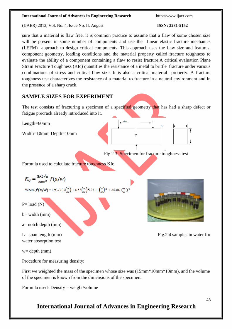
SAMPLE SIZES FOR EXPERIMENT
The test consists of fracturing a specimen of a specified geometry that has had a sharp defect or
fatigue precrack already introduced into it.
Length=60mm
Width=10mm, Depth=10mm
Fig.2.3: Specimen for fracture toughness test
Formula used to calculate fracture toughness KIc
P= load (N)
b= width (mm)
a= notch depth (mm)
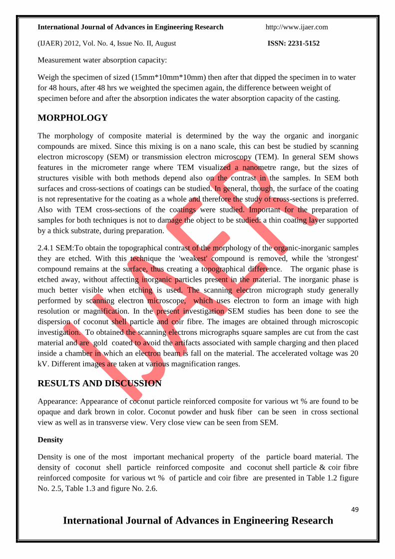
L= span length (mm) Fig.2.4 samples in water for
water absorption test
w= depth (mm)
Procedure for measuring density:
First we weighted the mass of the specimen whose size was (15mm*10mm*10mm), and the volume
of the specimen is known from the dimensions of the specimen.
Formula used- Density = weight/volume
International Journal of Advances in Engineering Research http://www.ijaer.com
(IJAER) 2012, Vol. No. 4, Issue No. II, August ISSN: 2231-5152
49
International Journal of Advances in Engineering Research
Measurement water absorption capacity:
Weigh the specimen of sized (15mm*10mm*10mm) then after that dipped the specimen in to water
for 48 hours, after 48 hrs we weighted the specimen again, the difference between weight of
specimen before and after the absorption indicates the water absorption capacity of the casting.
MORPHOLOGY
The morphology of composite material is determined by the way the organic and inorganic
compounds are mixed. Since this mixing is on a nano scale, this can best be studied by scanning
electron microscopy (SEM) or transmission electron microscopy (TEM). In general SEM shows
features in the micrometer range where TEM visualized a nanometre range, but the sizes of
structures visible with both methods depend also on the contrast in the samples. In SEM both
surfaces and cross-sections of coatings can be studied. In general, though, the surface of the coating
is not representative for the coating as a whole and therefore the study of cross-sections is preferred.
Also with TEM cross-sections of the coatings were studied. Important for the preparation of
samples for both techniques is not to damage the object to be studied: a thin coating layer supported
by a thick substrate, during preparation.
2.4.1 SEM:To obtain the topographical contrast of the morphology of the organic-inorganic samples
they are etched. With this technique the 'weakest' compound is removed, while the 'strongest'
compound remains at the surface, thus creating a topographical difference. The organic phase is
etched away, without affecting inorganic particles present in the material. The inorganic phase is
much better visible when etching is used. The scanning electron micrograph study generally
performed by scanning electron microscope, which uses electron to form an image with high
resolution or magnification. In the present investigation SEM studies has been done to see the
dispersion of coconut shell particle and coir fibre. The images are obtained through microscopic
investigation. To obtained the scanning electrons micrographs square samples are cut from the cast
material and are gold coated to avoid the artifacts associated with sample charging and then placed
inside a chamber in which an electron beam is fall on the material. The accelerated voltage was 20
kV. Different images are taken at various magnification ranges.
RESULTS AND DISCUSSION
Appearance: Appearance of coconut particle reinforced composite for various wt % are found to be
opaque and dark brown in color. Coconut powder and husk fiber can be seen in cross sectional
view as well as in transverse view. Very close view can be seen from SEM.
Density
Density is one of the most important mechanical property of the particle board material. The
density of coconut shell particle reinforced composite and coconut shell particle & coir fibre
reinforced composite for various wt % of particle and coir fibre are presented in Table 1.2 figure
No. 2.5, Table 1.3 and figure No. 2.6.
International Journal of Advances in Engineering Research http://www.ijaer.com
(IJAER) 2012, Vol. No. 4, Issue No. II, August ISSN: 2231-5152
50
International Journal of Advances in Engineering Research
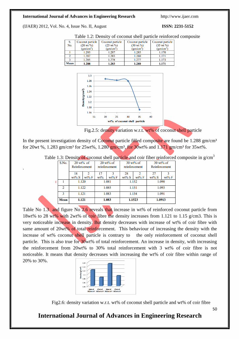
Table 1.2: Density of coconut shell particle reinforced composite
Fig.2.5: density variation w.r.t. wt% of coconut shell particle
In the present investigation density of Coconut particle filled composite are found be 1.288 gm/cm³
for 20wt %, 1.283 gm/cm³ for 25wt%, 1.280 gm/cm³, for 30wt% and 1.171 gm/cm³ for 35wt%.
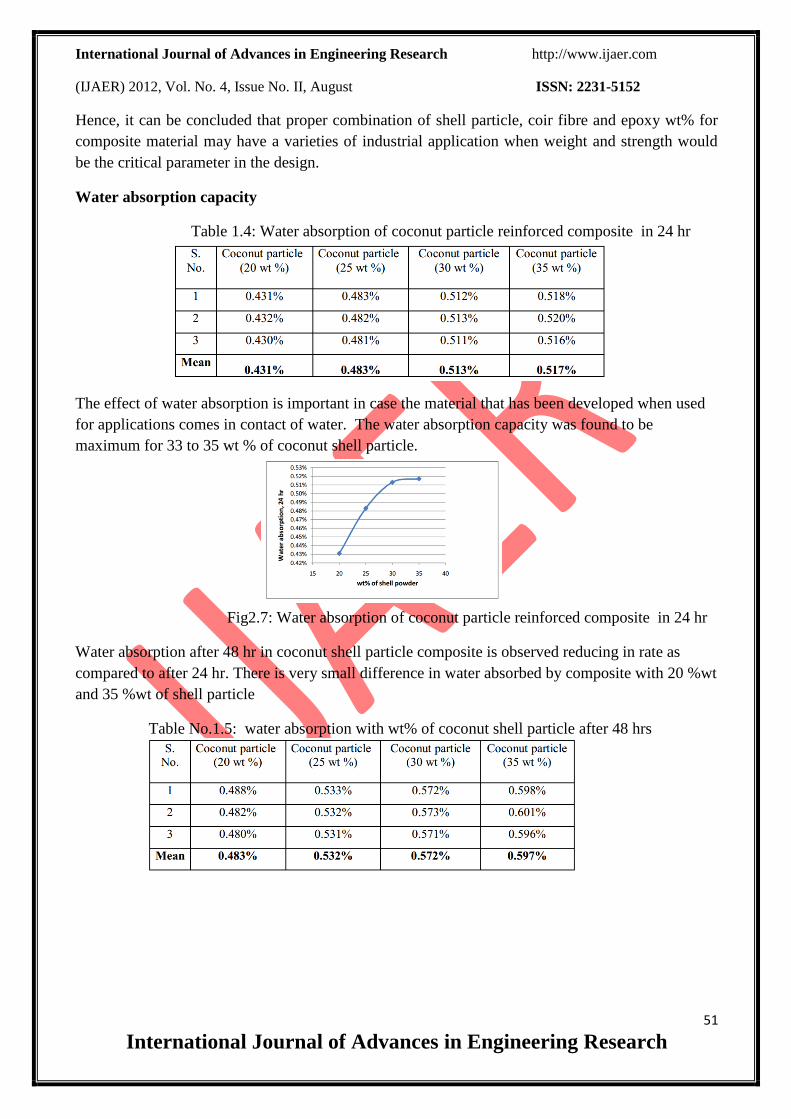
Table 1.3: Density of coconut shell particle and coir fiber reinforced composite in g/cm3
.
Table No 1.3 and figure No 2.6 reveals that increase in wt% of reinforced coconut particle from
18wt% to 28 wt% with 2wt% of coir fibre the density increases from 1.121 to 1.15 g/cm3. This is
very noticeable increase in density. But density decreases with increase of wt% of coir fibre with
same amount of 20wt% of total reinforcement. This behaviour of increasing the density with the
increase of wt% coconut shell particle is contrary to the only reinforcement of coconut shell
particle. This is also true for 30wt% of total reinforcement. An increase in density, with increasing
the reinforcement from 20wt% to 30% total reinforcement with 3 wt% of coir fibre is not
noticeable. It means that density decreases with increasing the wt% of coir fibre within range of
20% to 30%.
Fig2.6: density variation w.r.t. wt% of coconut shell particle and wt% of coir fibre
International Journal of Advances in Engineering Research http://www.ijaer.com
(IJAER) 2012, Vol. No. 4, Issue No. II, August ISSN: 2231-5152
51
International Journal of Advances in Engineering Research
Hence, it can be concluded that proper combination of shell particle, coir fibre and epoxy wt% for
composite material may have a varieties of industrial application when weight and strength would
be the critical parameter in the design.
Water absorption capacity
Table 1.4: Water absorption of coconut particle reinforced composite in 24 hr
The effect of water absorption is important in case the material that has been developed when used
for applications comes in contact of water. The water absorption capacity was found to be
maximum for 33 to 35 wt % of coconut shell particle.
Fig2.7: Water absorption of coconut particle reinforced composite in 24 hr
Water absorption after 48 hr in coconut shell particle composite is observed reducing in rate as
compared to after 24 hr. There is very small difference in water absorbed by composite with 20 %wt
and 35 %wt of shell particle
Table No.1.5: water absorption with wt% of coconut shell particle after 48 hrs
International Journal of Advances in Engineering Research http://www.ijaer.com
(IJAER) 2012, Vol. No. 4, Issue No. II, August ISSN: 2231-5152
52
International Journal of Advances in Engineering Research
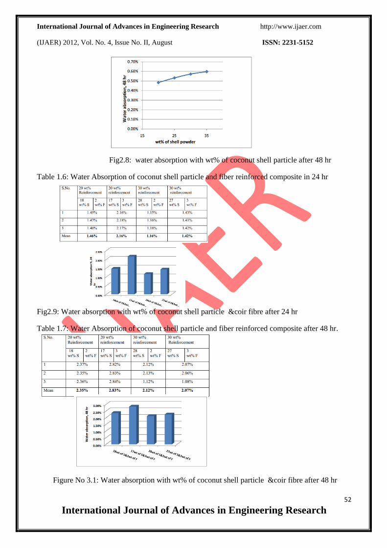
Fig2.8: water absorption with wt% of coconut shell particle after 48 hr
Table 1.6: Water Absorption of coconut shell particle and fiber reinforced composite in 24 hr
Fig2.9: Water absorption with wt% of coconut shell particle &coir fibre after 24 hr
Table 1.7: Water Absorption of coconut shell particle and fiber reinforced composite after 48 hr.
Figure No 3.1: Water absorption with wt% of coconut shell particle &coir fibre after 48 hr
International Journal of Advances in Engineering Research http://www.ijaer.com
(IJAER) 2012, Vol. No. 4, Issue No. II, August ISSN: 2231-5152
53
International Journal of Advances in Engineering Research
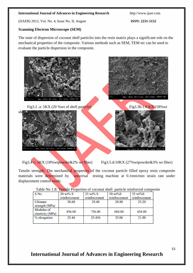
Scanning Electron Microscope (SEM)
The state of dispersion of coconut shell particles into the resin matrix plays a significant role on the
mechanical properties of the composite. Various methods such as SEM, TEM etc can be used to
evaluate the particle dispersion in the composite.
Fig3.2 .a: 5KX (20 %wt of shell particle) Fig3.3b:1.0 KX (18%wt
shell particle &2%wt coir fiber)
Fig3.4 c: 5KX (18%wtpowder&2% wt fiber) Fig3.5.d:10KX (27%wtpowder&3% wt fiber)
Tensile strength: The mechanical properties of the coconut particle filled epoxy resin composite
materials were determined by universal testing machine at 0.1mm/min strain rate under
displacement control mode.
Table No 1.8: Tensile Properties of coconut shell particle reinforced composite
International Journal of Advances in Engineering Research http://www.ijaer.com
(IJAER) 2012, Vol. No. 4, Issue No. II, August ISSN: 2231-5152
54
International Journal of Advances in Engineering Research
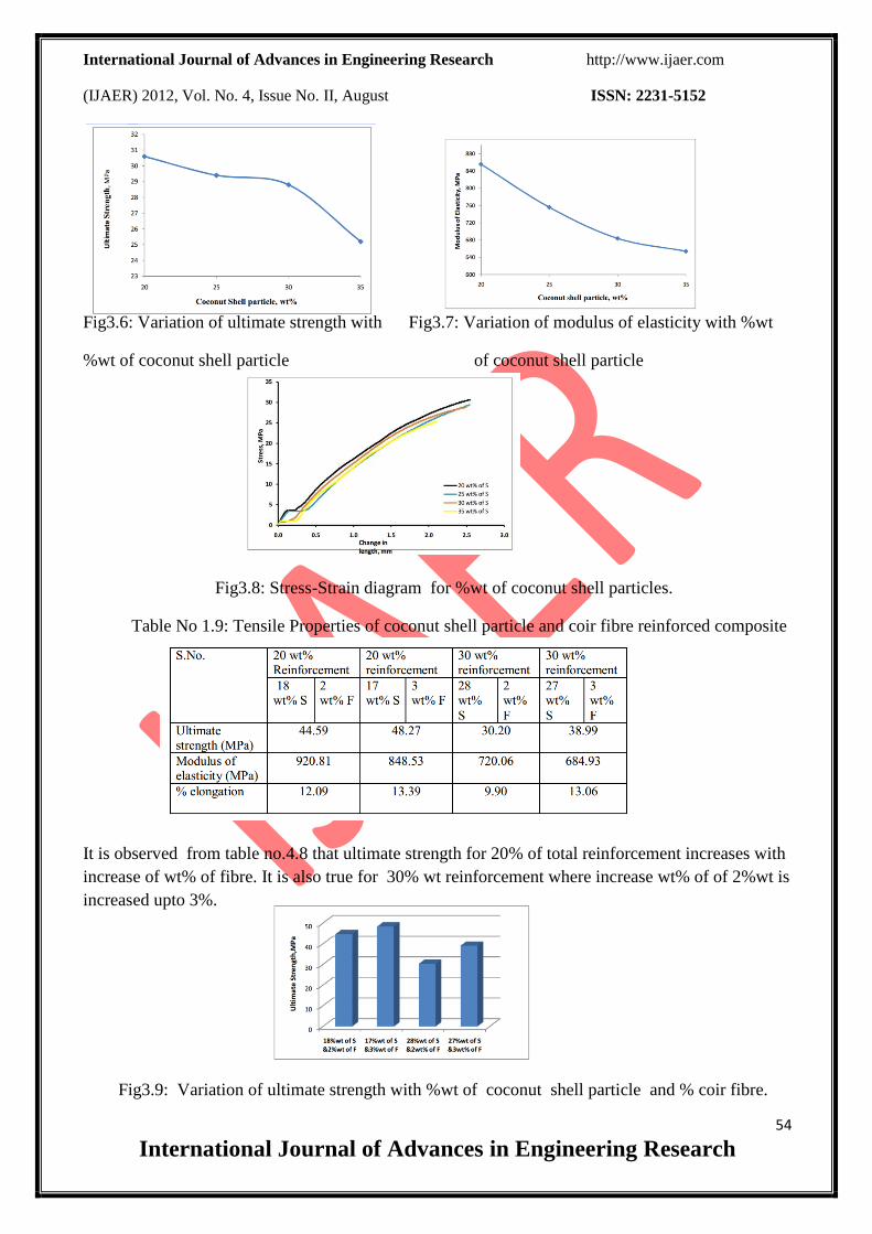
Fig3.6: Variation of ultimate strength with Fig3.7: Variation of modulus of elasticity with %wt
%wt of coconut shell particle of coconut shell particle
Fig3.8: Stress-Strain diagram for %wt of coconut shell particles.
Table No 1.9: Tensile Properties of coconut shell particle and coir fibre reinforced composite
It is observed from table no.4.8 that ultimate strength for 20% of total reinforcement increases with
increase of wt% of fibre. It is also true for 30% wt reinforcement where increase wt% of of 2%wt is
increased upto 3%.
Fig3.9: Variation of ultimate strength with %wt of coconut shell particle and % coir fibre.
International Journal of Advances in Engineering Research http://www.ijaer.com
(IJAER) 2012, Vol. No. 4, Issue No. II, August ISSN: 2231-5152
55
International Journal of Advances in Engineering Research
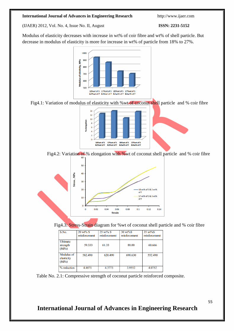
Modulus of elasticity decreases with increase in wt% of coir fibre and wt% of shell particle. But
decrease in modulus of elasticity is more for increase in wt% of particle from 18% to 27%.
Fig4.1: Variation of modulus of elasticity with %wt of coconut shell particle and % coir fibre
Fig4.2: Variation of % elongation with %wt of coconut shell particle and % coir fibre
Fig4.3: Stress-Strain diagram for %wt of coconut shell particle and % coir fibre
Table No. 2.1: Compressive strength of coconut particle reinforced composite.
International Journal of Advances in Engineering Research http://www.ijaer.com
(IJAER) 2012, Vol. No. 4, Issue No. II, August ISSN: 2231-5152
56
International Journal of Advances in Engineering Research
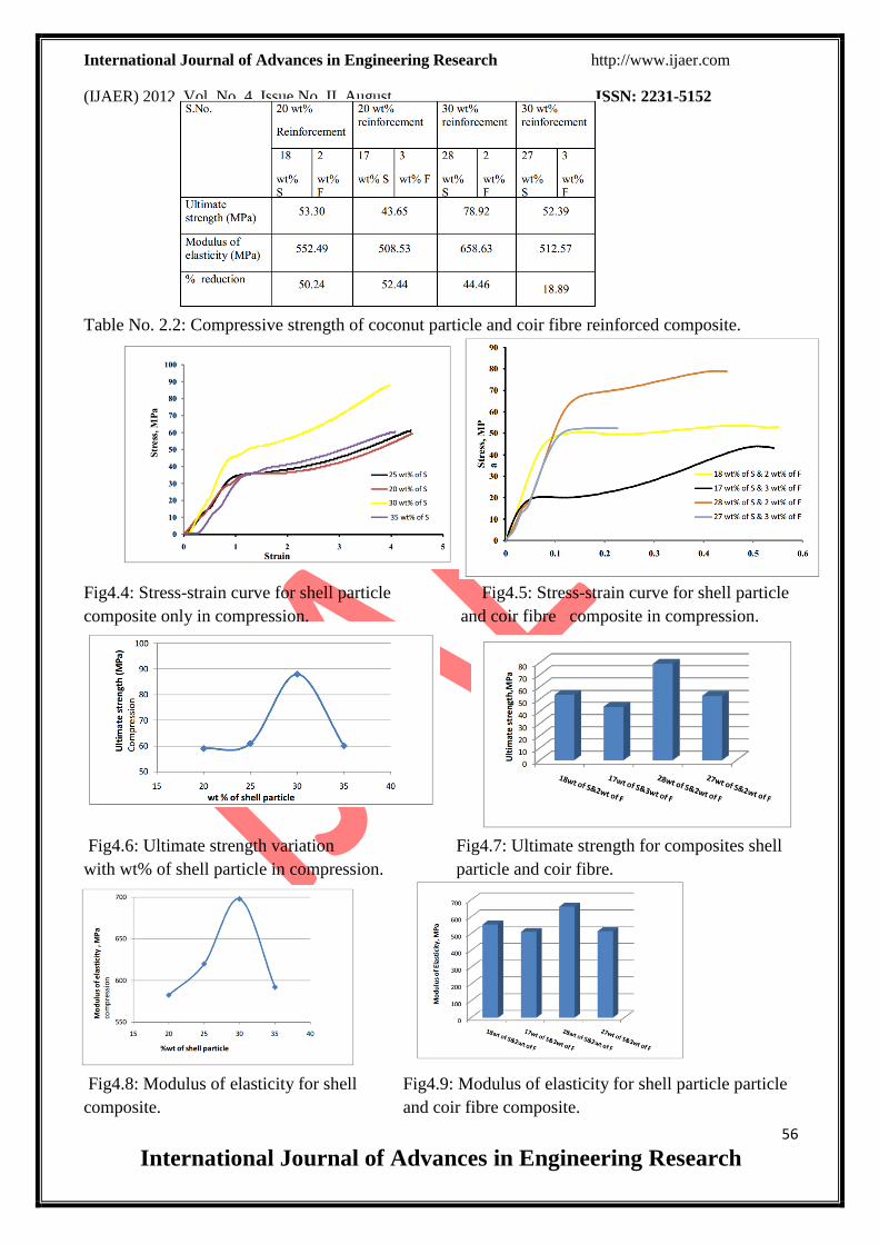
Table No. 2.2: Compressive strength of coconut particle and coir fibre reinforced composite.
Fig4.4: Stress-strain curve for shell particle Fig4.5: Stress-strain curve for shell particle
composite only in compression. and coir fibre composite in compression.
Fig4.6: Ultimate strength variation Fig4.7: Ultimate strength for composites shell
with wt% of shell particle in compression. particle and coir fibre.
Fig4.8: Modulus of elasticity for shell Fig4.9: Modulus of elasticity for shell particle particle
composite. and coir fibre composite.
International Journal of Advances in Engineering Research http://www.ijaer.com
(IJAER) 2012, Vol. No. 4, Issue No. II, August ISSN: 2231-5152
57
International Journal of Advances in Engineering Research
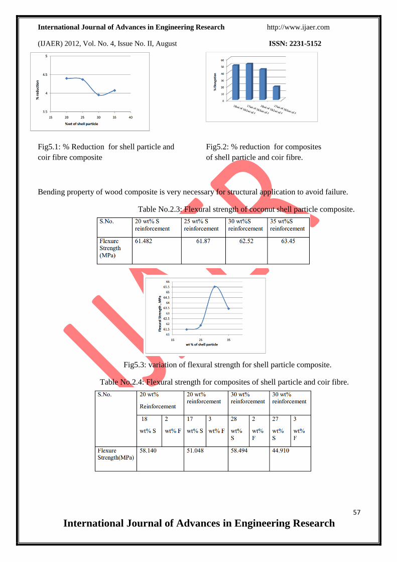
Fig5.1: % Reduction for shell particle and Fig5.2: % reduction for composites
coir fibre composite of shell particle and coir fibre.
Bending property of wood composite is very necessary for structural application to avoid failure.
Table No.2.3: Flexural strength of coconut shell particle composite.
Fig5.3: variation of flexural strength for shell particle composite.
Table No.2.4: Flexural strength for composites of shell particle and coir fibre.

International Journal of Advances in Engineering Research http://www.ijaer.com
(IJAER) 2012, Vol. No. 4, Issue No. II, August ISSN: 2231-5152
58
International Journal of Advances in Engineering Research
Fig5.4: Flexural strength of shell particle and coir fibre reinforced composite.
Table No2.5: Fracture toughness of shell particle composites.
Table No.2.5: Fracture toughness of shell particle and coir fibre reinforced composites.
Fig5.5: Fracture toughness of shell particle composites.
International Journal of Advances in Engineering Research http://www.ijaer.com
(IJAER) 2012, Vol. No. 4, Issue No. II, August ISSN: 2231-5152
59
International Journal of Advances in Engineering Research
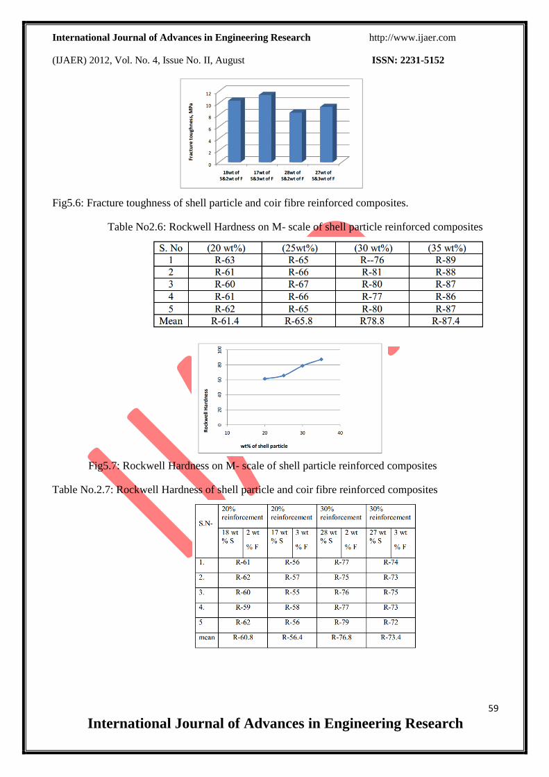
Fig5.6: Fracture toughness of shell particle and coir fibre reinforced composites.
Table No2.6: Rockwell Hardness on M- scale of shell particle reinforced composites
Fig5.7: Rockwell Hardness on M- scale of shell particle reinforced composites
Table No.2.7: Rockwell Hardness of shell particle and coir fibre reinforced composites
International Journal of Advances in Engineering Research http://www.ijaer.com
(IJAER) 2012, Vol. No. 4, Issue No. II, August ISSN: 2231-5152
60
International Journal of Advances in Engineering Research
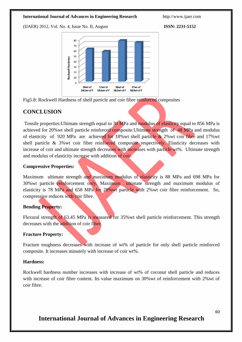
Fig5.8: Rockwell Hardness of shell particle and coir fibre reinforced composites
CONCLUSION
Tensile properties:Ultimate strength equal to 30 MPa and modulus of elasticity equal to 856 MPa is
achieved for 20%wt shell particle reinforced composite.Ultimate strength of 48 MPa and modulus
of elasticity of 920 MPa are achieved for 18%wt shell particle & 2%wt coir fibre and 17%wt
shell particle & 3%wt coir fibre reinforced composite respectively. Elasticity decreases with
increase of coir and ultimate strength decreases with increases with particle wt%. Ultimate strength
and modulus of elasticity increase with addition of coir.
Compressive Properties:
Maximum ultimate strength and maximum modulus of elasticity is 88 MPa and 698 MPa for
30%wt particle reinforcement only. Maximum ultimate strength and maximum modulus of
elasticity is 78 MPa and 658 MPa for 28%wt particle with 2%wt coir fibre reinforcement. So,
compressive reduces with coir fibre.
Bending Property:
Flexural strength of 63.45 MPa is measured for 35%wt shell particle reinforcement. This strength
decreases with the addition of coir fibre.
Fracture Property:
Fracture toughness decreases with increase of wt% of particle for only shell particle reinforced
composite. It increases minutely with increase of coir wt%.
Hardness:
Rockwell hardness number increases with increase of wt% of coconut shell particle and reduces
with increase of coir fibre content. Its value maximum on 30%wt of reinforcement with 2%wt of
coir fibre.

International Journal of Advances in Engineering Research http://www.ijaer.com
(IJAER) 2012, Vol. No. 4, Issue No. II, August ISSN: 2231-5152
61
International Journal of Advances in Engineering Research
REFERENCES
1.Devi K.A.; Nair C.P.R and Ninan K.N. (2003). Journal of Polymers and Polymer Composites.
Vol. 11.pp.551-558
2.Dultseva L.D.; Suvorov, A.L.; Ostanina N.Y.; Shtrova, Y.V.; Survorova A.I. (2003). Journal of
Int. Polymer Science and Technology. Vol. 30, pp.T/42-46.
3. Durand J. M., Vardavanlias M., Teandin M.(1995). Role of reinforcing ceramic particle in the
wear behavior based model composites. Wear, 181-183, 837-839.
4. Ellis B.(1993). Chemistry and Technology of Epoxy Resins. Blackie, London.
5. Erdogan F, Sih GC. (1963). On the crack extension in plates under plane loading and transverse
shear", Journal of Basic Engineering, Transactions of the ASME, Vol. 85D pp.519-27.
6. Fowkes, F.M. (1987). J. Adhes. Sci. Tech, Vol.1, pp.7.
7. Flowe, Harvey M. (1995). High performance materials in aerospace, pp.202-226.
8.Gracia M., Vilate G. Van, Jain S., Sahreuwen B. A.G.,Sarkissov A., Zyl W. E. Van, Boukemp B.
(2004). Polypropylene/SiO2 Nanocomposites With Improved Mechanical Properties. Rev. Adv.
Material Science 6 pp. 169-175.
9.Gould, R.F.(ed.) 1970. Epoxy resins (Advances in chemistry series No.92). American Chemical
Society, Washington.
10.Guhartz, Wolfgang and Yamamoto, Y. Stephen. (1986). Ullmann’s Encylopedia of Industrial
Chemistry,Vol.47, pp.369-410.
11.Guru M, Atar M and Yildirim R, 2008, “Production of polymer matrix composite particle board
from wallnut shell and improvement of its requirements”, Materials and Design, Volume 29, Issue
1, Pages 284-287.
12.Gupta N, Karthikeyan C S, Sankaran S and Kishore. (1999). Mater. Char. 14 271Guo, B; Fu, W,;
Jid, D.; Qui, Q. and Wang L. (2002). Journal of Polymers and Polymers composites. Vol 10.
pp.237-248.
13. Guo Q. B., Min Zhi Rong M. Z., Guo L. J., Lau K.T., Zhang M.Q.(2009). Sliding wear
International Journal of Advances in Engineering Research http://www.ijaer.com
(IJAER) 2012, Vol. No. 4, Issue No. II, August ISSN: 2231-5152
62
International Journal of Advances in Engineering Research
performance of nano-SiO2/short carbon fiber/epoxy hybrid composites. Wear. Volume 266, Pages
658-665. Hill, R. (1964a). J. of Mech. Phys. Solids, Vol.12, pp.199-212.
14. Holmberg, K. and Wickstorm, G. (1987). Wear, Vol.115, pp.95-105.
15. Hyung Jin Kim, Sung Wi Koh, Jae Dong Kim and Byung Tak Kim. (2007). Materials Science
Forum Vols. 544-545 pp 267-270.
16. Hashim Defence Science Journal”, Volume 58, No. 2,Pages. 248-263
17. Isayev, A.I.and Modic, M.J. (1986). Society of plastics Engineers 44thAnnual Technical
Conference and Exhibit, pp.373-579.
18. Jensen, R.J.; Cumming, J.P. and Vora, H. (1987). Proc. IEEE Electronic Component
Conference, pp.73.