study of power conditioning system of …
TRANSCRIPT

STUDY OF POWER CONDITIONING
SYSTEM OF SUPERCONDUCTING
MAGNETIC ENERGY STORAGE
SYSTEM
Bhagyashree Mishra
Department of Electrical Engineering
National Institute of Technology, Rourkela
May 2014

STUDY OF POWER CONDITIONING
SYSTEM OF SUPERCONDUCTING
MAGNETIC ENERGY STORAGE SYSTEM
A Thesis Submitted In the Partial Fulfillment of the
Requirements for the Degree Of
Master of Technology
In
Electrical Engineering
By
Bhagyashree Mishra (Roll No: 212ee4392)
Under the Guidance of
Prof. Anup Kumar Panda
Department of Electrical Engineering
National Institute of Technology, Rourkela
May 2014

Dedicated to my beloved parents and my brother

ACKNOWLEDGEMENT
I would like to express my sincere gratitude to my supervisor
Prof. Anup Kumar Panda for his guidance, encouragement, and
support throughout the course of this work. It was an invaluable
learning experience for me to be one of his students. From him I have
gained not only extensive knowledge, but also a sincere research
attitude.
I express my gratitude to Prof. Anup Kumar Panda, Head of the
Department, Electrical Engineering for his invaluable suggestions and
constant encouragement all through the research work. My thanks are
extended to my friends in “Power Electronics and Drives” who built
an academic and friendly research environment that made my study at
NIT, Rourkela most memorable and fruitful.
I would also like to acknowledge the entire teaching and non-teaching
staff of Electrical Department for establishing a working environment
and for constructive discussions. Finally, I am always indebted to all
my family members especially my parents, for their endless love and
blessings.
Bhagyashree Mishra
Roll No: 212ee4392

CERTIFICATE
This is to certify that the Thesis Report entitled “STUDY OF
POWER CONDITIONING SYSTEM OF
SUPERCONDUCTING MAGNETIC ENERGY STORAGE
SYSTEM”, submitted by Ms. BHAGYASHREE MISHRA bearing
roll no. 212EE4392 in partial fulfillment of the requirements for the
award of Master of Technology in Electrical Engineering with
specialization in “Power Electronics and Drives” during session 2012-
2014 at National Institute of Technology, Rourkela is an authentic
work carried out by her under my supervision and guidance.
To the best of my knowledge, the matter embodied in the thesis has
not been submitted to any other university/institute for the award of
any Degree or Diploma.
Date: Prof. Anup Kumar Panda
Place: Rourkela Department of Electrical Engineering
National Institute of Technology
Rourkela-769008
Email: [email protected]
DEPARTMENT OF ELECTRICAL ENGINEERING
NATIONAL INSTITUTE OF TECHNOLOGY ROURKELA
ODISHA, INDIA

CONTENTS
Abstract i
List of Figures ii
List of Tables iii
CHAPTER-I
1.1 Introduction 1
1.2 Literature review 2
1.3 Research Motivation 4
1.4 Objective 5
1.5 Thesis Organization 5
CHAPTER-II
2.1 Superconducting Magnetic energy System (SMES) 7
2.2 Practical Utilities of SMES 8
2.3 advantages of SMES 8
CHAPTER-III
3.1 Principle of operation 12
3.2 System topology 14
3.2.1.1 VSC based SMES 14
3.2.1.2 CSC based SMES 15
3.2.2 DC/DC Converter 18
CHAPTER-IV
4.1 Hysteresis band Controller 20
4.2 fuzzy Logic Controller 22
4.3 Control strategy 25
CHAPTER-V
5.1 Simulation and Results 28
5.2 Discussion and Conclusion 35
5.3 Future Scope 36
References 37

i
ABSTRACT
A Superconducting Magnetic Energy Storage System (SMES) can be utilized for the
compensation of nonlinear and pulsating loads. In this paper a power conditioning system
(PCS) is designed to achieve SMES to work as a shunt active power filter and power
conditioner at the same time. Two Hysteresis band controllers have been implemented to
obtain (i) a sinusoidal input source current in phase with fundamental component of line to
neutral source voltage irrespective of the load conditions (ii) Charging and discharging of
SMES under constant voltage control mode. DC link voltage is kept constant by DC/DC
Bidirectional Converter and source current is controlled by Voltage Source Converter (VSC).
The magnitude of reference source current is obtained by controlling the energy of SMES by
using Fuzzy Logic Controller (FLC). As it is a nonlinear controller it gives better
performance than previously used PI controller in parameter variations and load disturbances.
Analysis of the circuit operation under Fuzzy controller is presented in detail. Simulation has
been done in MATLAB/Simulink and results are presented demonstrating the feasibility of
the proposed power conditioning system.

ii
LIST OF FIGURES
Fig. No. Figure Description Page No.
Fig 2.1 Basic structure of SMES unit 8
Fig 3.1 Operation of PCS under Load leveling 14
Fig 3.2.1 Proposed System topology 17
Fig 3.2.1.1 PCS using Voltage Source Converter 15
Fig 3.2.1.2 PCS using Current Source Converter 16
Fig 3.2.2 Two quadrant voltage bidirectional DC/DC Converter 19
Fig 4.1 Operation of Hysteresis Controller 21
Fig 4.2.1 Block diagram of Fuzzy Logic Controller 23
Fig 4.2.2 Input membership functions of Fuzzy Logic Controller 24
(a) Membership function of error (E)
(b) Membership Function of change in error (∆E)
(c) Membership function of change in magnitude of reference
source current (∆I)
Fig 4.3.1 Proposed control strategy 26
Fig 4.3.2 Proposed Fuzzy Controller 27
Fig 4.3.3 Switching pulses generation for VSC 27
Fig 5.1.1 Variation of source voltage with time using PI controller 28
Fig 5.1.2 Variation of load current with time using PI controller 29
Fig 5.1.3 Variation of 3ph source current with time using PI controller 29
Fig 5.1.4 Variation of 1ph source current with time using PI controller 29
Fig 5.1.5 Variation of SMES coil current with time using PI controller 30
Fig 5.1.6 Variation of dc-link voltage with time using PI controller 30
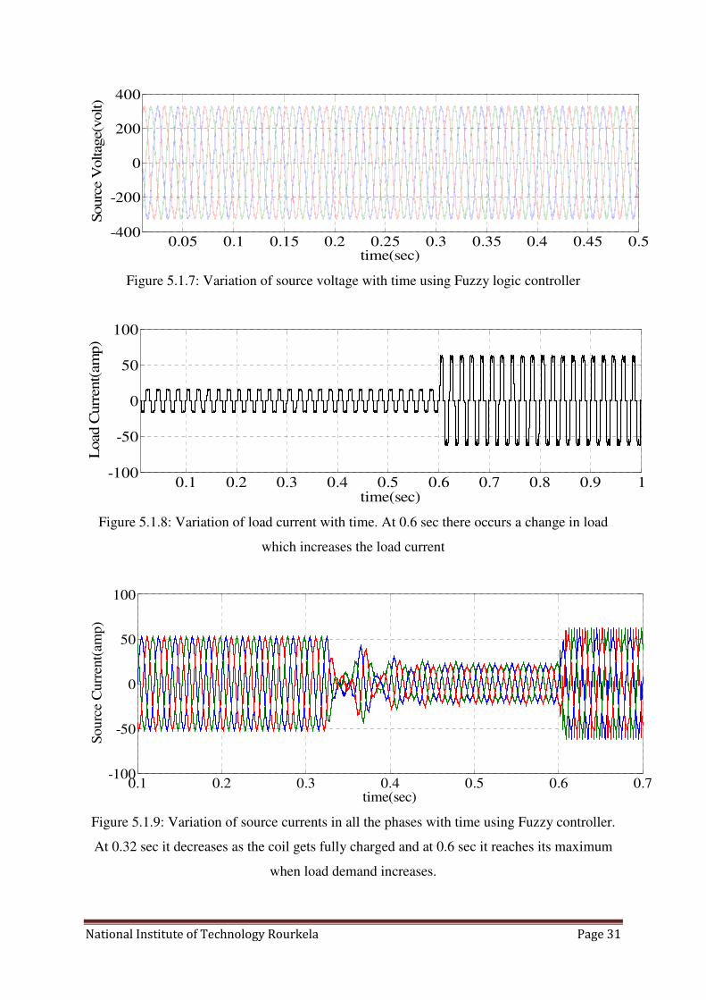
Fig 5.1.7 Variation of source voltage with time using Fuzzy controller 31
Fig 5.1.8 Variation of load current with time using Fuzzy controller 31
Fig 5.1.9 Variation of 3ph source current with time using Fuzzy controller 31
Fig 5.1.10 Variation of 1ph source current with time using Fuzzy controller 32
Fig 5.1.11 Variation of SMES coil current with time using Fuzzy controller 32
Fig 5.1.12 Variation of dc-link voltage with time using Fuzzy controller 32
Fig 5.1.13 THD in source current in charging mode of SMES using PI controller 33

iii
Fig 5.1.14 THD in source current in standby mode of SMES using PI controller 33
Fig 5.1.15 THD in source current in discharging mode of SMES using PI controller 33
Fig 5.1.16 THD in source current in charging mode of SMES using Fuzzy controller 34
Fig 5.1.17 THD in source current in standby mode of SMES using Fuzzy controller 34
Fig 5.1.18 THD in source current in discharging mode of SMES using 34
Fuzzy controller
LIST OF TABLES
Table No. Table Description Page No.
Table 3.2.1: Comparison between VSC and CSC based PCS 17
Table 4.2: Rule base of Fuzzy Logic Controller 25
Table 5.1: Comparison between PI and Fuzzy controller in terms of THD 35
contained in source current

CHAPTER I
1.Introduction
2.Literature review
3.Research motivation
4.Objective
5.Thesis Organization

National Institute of technology Rourkela Page 1
1.1 Introduction
Superconductivity is a phenomenon of exactly zero resistance occurring in some materials
when their temperature goes below a certain critical temperature. SMES (Superconducting
Magnetic Energy Storage System) is a long superconducting coil that has the ability to store
energy in the form of magnetic field generated by the direct current flowing in it up to
indefinite instant. Applications of Superconducting Magnetic Energy Storage system (SMES)
are being studied and presented in many papers in recent years. Some important applications
include energy storage, system stability enhancement, diurnal load leveling and voltage
stability (Transient and dynamic), static VAR compensation, current harmonics mitigation.
The demand of electricity from consumers and industries is constantly changing from time to
time. During peak load hour as the demand increases the voltage at the load end starts falling
leading to voltage instability and collapse of total power system if load leveling is not done
for the continuation of power supply. Load leveling plays an important role in case of
industrial load where violation of maximum power demands and power factor causes penalty
to the industry concern. Load leveling can be ensured by storing the excessive energy of
source during low-load hours and delivering the stored energy back in peak load hour. To
satisfy the above criteria, energy storage devices are usually required such as batteries or
superconducting magnetic energy storage systems [1].
For the above applications the power conditioning system of SMES consists of a voltage
source converter (VSC) and a DC/DC bidirectional converter. As SMES acts as a DC current
source, choice of current source converter (CSC) is obvious. But due to large fluctuations in
current and voltage across SMES coil a high power rated CSC is required which becomes
impractical [2]. So, VSC is the alternative choice and it requires a DC/DC converter to
connect the current controlled SMES to voltage controlled converter. Both the converters are
decoupled by dc-link. The first converter VSC interfaces dc-link with the ac supply system. It
is regulated to obtain a source current in phase with source voltage irrespective of the load
conditions. DC/DC bidirectional converter is used to control charging and discharging of
SMES coil. Making the dc-link voltage constant ensures direct exchange of power between
grid and coil.
Due to inherent simplicity and benefits Hysteresis band controller is used to control both the
two converters [5], [6]. In the voltage source converter it is used to control the source current,

National Institute of technology Rourkela Page 2
thus acting as a active power filter and in dc/dc converter it controls the charge-discharge
cycle and the dc-link capacitor voltage. Hysteresis controller creates a band to bind the
controlled variable within it. Switching pulses are generated when the controlled variable
reaches the upper and lower bounds. A Fuzzy Logic Controller (FLC) is used to control the
SMES coil energy that indirectly controls the charging and discharging of coil. Previously, PI
controller was used to control the coil energy, but in this paper a nonlinear FLC is introduced
whose performance is better than PI controller. The output of fuzzy logic controller is taken
as the magnitude of reference source current. Magnitude of source current is varied during
the whole day to control the charge-discharge cycle of SMES using FLC. Practically, the
operation of a superconductor is in form of pulsed signals that leads to ac current losses in the
coil. These losses should be taken into account during the design of the SMES refrigeration
system [3].
1.2 Literature Review
Since last forty years research and investigations in the area of Superconducting Magnetic
Energy System (SMES) has been emerged. In early 1970's vigorous investigations were
started by the University of Wisconsin and by The Department of Energy at Los Alamos
National Laboratory [11]. Again during 1980's a case study to analyze the technical and
economic advantages of a SMES for practicality was started by the Electric Power Research
Institute (EPRI). In 1983 the Department of Energy in association with the Bonneville Power
Administration did experiment on a 30 MJ SMES unit on the Western US Power System to
dampen power oscillations on the Pacific Intertie [12]. During that time the Department of
Defense showed interest in SMES technology as a viable source of power in form of pulse to
be supplied to the Ground Based Free Electron Laser (GBFEL) [13].
As a result of this, a program was sponsored by the Defense Nuclear Agency to design,
invent and test a 22 MWhr - 400 MW SMES Engineering Test Model (ETM). The ETM has
the following two objectives: (1) To assess the viability of using a SMES system to ensure
load leveling and enhance system stability for remunerative and electrical usage. (2) To
demonstrate the practicality of using the SMES system as a pulsed power source to power
ground based defense systems [2]. In this project the SMES-ETM consists of two groups of
two series connected superconducting coils each having rating of 50A 61.2H. The Power
Conditioning System (PCS) consists of four modules each of 100 MW 24-pulse Voltage

National Institute of technology Rourkela Page 3
source converters (VSC), a two quadrant chopper and dc-link capacitor to connect the
superconducting coil with the ac supply system. The 24-pulse VSC consists of four 3 phase
6-pulse 25 MW VSCs and the switching device is GTO anti-parallel with diode. To produce
actual 24-pulse waveform four star-delta transformers with appropriate phase differences are
connected in parallel. Here output real and reactive power is controlled to generate the pulse
of GTO and SMES coil currents in the two groups are dynamically balanced by a differential
real power command.
Initially to interface the SMES with the supply network current source converters (CSC) were
used [59] – [60] as SMES is a current controller device. The charging and discharging of
SMES can be controlled directly by regulating the switching pulses of CSC. In this topology
SMES is connected to CSC on one side and the ac power network on the other side. As
SMES is inherent current source the exchange of active and reactive power becomes fast and
independent by using CSC.
In the year 1998, a power conditioning system that can be used for the mitigation of nonlinear
and pulsating loads, was proposed [14]. In this thesis the VSC used is IGBT based and three
PI controllers are used to regulate the SMES energy, dc-link capacitor voltage and the source
current. The main objective was to make source current in phase with source voltage
irrespective of nonlinear loads. The control loops were analyzed to determine the gains of the
three controllers.
All the PCS developed till 2003 were controlling the SMES in voltage controlled mode. In
this mode SMES is charged under constant voltage which takes more time. An improved
controller is proposed and the main objective of the proposed improved controller is to
rapidly charge the superconducting coil with charging under constant current to ensure that it
can be used for the next discharging cycle in a minimum time [15]. The charging of SMES
coil is done under constant current mode and discharging done in constant voltage mode to
have an instantaneous response. To have this control the PCS is implemented with a
bidirectional converter with a single pole double throw (SPDT) switch. The VSC used is
IGBT based and control of source current is done using linear PI regulator.
For controlling the desired system parameters converters are required to be controlled
nonlinear controller whenever there occurs a change in operating conditions. Previously,
simple linear PI controllers were used to control the source current which does not give

National Institute of technology Rourkela Page 4
satisfactory performance during parameter variations. To have better performance nonlinear
controllers are introduced such ac Fuzzy Logic controller, Neural Networks. Since several
past years fuzzy control technique is adapted as the most accurate and viable area of
investigation in the application of fuzzy set theory [16].
The pioneering research of Mamdani and his colleagues on fuzzy control [17]-[20], [21] was
inspired by Zadeh's seminal papers on the linguistic approach and system analysis based on
the theory of fuzzy sets [22], [23],[25], [26]. Fuzzy Logic controller does not need the exact
mathematical modeling of the system and it is a trial and error procedure which can be
developed from past experiences just like human thinking. At present there no methodology
to design a fuzzy control system but C. C. Lee has summarized some fuzzy systems, which
includes fuzzification and defuzzification methods, the derivation of the database and fuzzy
control rules, the definition of a fuzzy implication and an analysis of fuzzy reasoning
mechanisms in [27].
Except of load leveling and harmonics filtration SMES can be in other purposes which are
describes in [31]-[55]. Some important applications of SMES are voltage stability, tie-line
power control and load frequency control, synchronous resonance damping, spinning reserve,
system stability, which is described in section 2.3.
1.3 Research Motivation
Except of superconducting magnetic energy storage system there are many techniques to
store energy such as battery storage (BESS) and pumped hydro electric systems. But these
systems suffers from drawbacks such as limitation in life span, injection of hazardous
materials to the environment, constraints in ratings in case of BESS and limitation in
environmental and geographical conditions along with requirement of large space for hydro
electric plant [4]. In case of SMES once dc current flows in the coil it can store energy for
indefinite periods and discharges it instantaneously as theoretically it has zero resistance,
hence zero time delay. This property makes SMES to discharge practically in milliseconds.
Load leveling is essential in modern power system to supply the increasing power
requirements and to avoid the collapse of supply network.

National Institute of technology Rourkela Page 5
Due to advancement of technologies, applications of non-linear load using static power
converter has been increased causing injection of harmonics. Various active power filter
topologies and control strategies have been developed [7]-[10], but shunt active power filters
have been emerged as the most fruitful alternative to mitigate current harmonic. Series
compensation is used to inject voltage at a specific angle with the supply voltage in case of
sag and swell. On the other hand, shunt compensation is used to inject current to optimize
source current for active power filtering. SMES has the property of controlling real and
reactive power independently. So, the power conditioning system (PCS) of SMES can be
controlled to eliminate current harmonics and to act as an active power filter as well as power
conditioner which is connected in shunt with the supply network.
1.4 Objective
The main objectives of this work are
i. To perform load leveling using SMES. Energy is stored in off-peak hours and
discharged in peak load hour to avoid instability of the system.
ii. In addition to give back-up supply SMES is regulated to obtain source current in
phase with phase-to-neutral source voltage so as to act as a shunt active filter. The real
and reactive power delivered to the load is controlled independently.
iii. The DC-link voltage is made constant to ensure direct exchange of energy between
source and SMES.
iv. To control the charge-discharge cycle of SMES so that it can be charged up to the
rated current. The SMES energy is controlled to achieve this.
1.5 Thesis Organization
The thesis organization is described below
CHAPTER-I contains the introduction to superconductivity and how it is utilized to satisfy
the desired function in power system. The cause or motivation for which the research was
done is also described. The techniques to solve the problem statement proposed in past years
were studied and presented in literature review. Finally from research motivation and

National Institute of technology Rourkela Page 6
literature review, the objectives of the research work were decided which is shown in this
chapter.
CHAPTER-II includes introduction to Superconducting Magnetic Energy Storage System
(SMES), its applications in power system to enhance stability, increase damping and many
others. Also the applications of superconducting materials in electrical machines, power
cables, transformers etc are described in this chapter.
CHAPTER-III presents the principle of operation of SMES connected with grid in which
energy balanced theorem is applied. Then the proposed topology for Power Conditioning
System (PCS) is described after comparing all the possible topologies.
CHAPTER-IV describes the control strategy of SMES to control the source current, dc-link
voltage and charge-discharge cycle of SMES. The construction and principle of operation of
controllers used, which are Fuzzy Logic controller and Hysteresis band controller, are also
included in this chapter.
CHAPTER-V is the final chapter in which results obtained by simulating the model is
presented. Along with this all the results were compared and discussed. It also contains the
conclusion and future scope of the proposed research work.

CHAPTER II
1.Superconducting Magnetic Energy
Storage System (SMES)
2.Practical Utilities of SMES
3.Applications of SMES

National Institute of Technology Rourkela Page 7
2.1 Superconducting Magnetic Energy Storage System
An SMES is a device that mainly reserve energy in the form of magnetic field. The dc current
flowing in a superconducting coil, which is wound around a long core magnet, creates the
magnetic field. Here, as the stored energy is in form of circulating current, it can be
consumed from an SMES unit with spontaneous response. Here, also energy can be reserved
or supplied over short or long periods lasting from milliseconds to many hours. An SMES
unit [fig 2.1] includes of a large superconducting coil, whose temperature is maintained
below the cryogenic temperature by a cryostat or Dewar that contains either helium or
nitrogen liquid as the coolant. During standby condition, to reduce the energy losses a bypass
switch is used. It also has certain merits that include shorting dc coil current if existing tie
line is lost, give protection to the coil if cooling is lost or disconnecting power converters
from service [28]. Several factors are considered in the design of the coil to obtain the desired
optimum possible performance of an SMES system at the economic cost [29]. Some
important factors are coil fabrication, energy reserve capability, topology and operating
temperature. A trade-off is made among each factor keeping eyes on the parameters of
energy/mass ratio, Lorentz forces, stray magnetic losses, and minimizing the losses for an
authentic, stable, and cost effective SMES system. The structure of SMES coil can be either
as a solenoid or a toroid. Due to its simplicity and economy, the solenoid type [30] has been
widely preferred. The rating of SMES unit is decided by its requirement needed. According
to the rating or energy/power capacity of SMES, the coil inductance and current rating as
well as the optimum voltage and current rating of PCS is determined. The operating
temperature of a superconducting device is a trade-off among economic and the operational
needs. Low-temperature superconductor (LTS) devices are generally utilized at present, while
high-temperature superconductor (HTS) devices are needed to be developed with high
efficiency and less cost.

National Institute of Technology Rourkela Page 8
Figure 2.1: Basic Structure of SMES Unit
2.2 Practical usage of SMES:
1. Induction heating
2. Fault current Limiter
3. Superconducting power cables
4. Superconducting Power Transformer
5. Rotating electrical machines with superconducting windings
6. Cryo-machines and electrical machines with massive superconductors
7. Super conducting magnetic energy storage system (SMES)
8. Magneto hydrodynamic generators (MHD)
9. Electrodynamic Levitation (e.g., high speed trains)
10. Particle accelerator (detector magnets, beam guidance magnets)
11. Synchrotron radiation sources
2.3 Applications of SMES:
1. Energy storage:
An SMES has the potential to become a reservoir of energy rated up to 5000 MWhr
with an exceptional exchange efficiency (up to 95%) as well as an instantaneous
response time for dynamic change of energy flow (milliseconds) [31]–[39]. For this
prospective SMES is essential for large variations in energy demands between peak-
load demand in day-hours and off-peak hours as well as huge quantity of
stored/reserved energy for the alternative of major unit failure. This can be an
alternative to the requirement of spinning reserve.

National Institute of Technology Rourkela Page 9
2. Load following:
An SMES unit has an inherent quality to follow system load changes almost with no
time delay which ensures the output power generated by conventional generating
units to be constant. [31], [34].
3. System stability:
Whenever there is a transient in power system, it results in low frequency power
oscillations. SMES unit takes care of it and damp it out so that frequency can be
stabilized. [31], [32], [40], [41], [54], [55].
4. Minimization of ACE:
An SMES unit can be the key operator in an AGC control loop to reduce the area
control error up to a minimum value (ACE) [31].
5. Spinning reserve
“Spinning reserve” is the amount of generated power that is unused or stored in order
to supplement during major energy loss or tripping of a large generating unit or major
transmission line. An SMES unit has a tremendous amount of energy storage capacity
when it is in the charging mode with its rated current. This lowers the costs for
spinning reserve requirements over comparable values. [31], [32], [34].
6. Reactive Power control and power factor Correction
An SMES unit can extend the stability limit and enhance the power carrying capacity
of a transmission system by improving the power factor [31].
7. Black start capability
An SMES unit can provide power to turn on a generating unit without taking power
from the grid. This provides for grid restoration when area failures have occurred
[31].
8. Bulk energy management
An SMES unit has the ability to store large quantities of energy, and thus can act as a
storage and transfer point for bulk quantities of energy based on the economics,
potentially lowering the cost of electricity [31].
9. Transient voltage dip improvement
Transient voltage sag occurring for many cycles can result when a large disturbance
on the power system occurs. SMES and associated converter equipment has been
demonstrated to be successful for providing voltage support which can result in
increasing the limits of power transfer in the transmission system [35].

National Institute of Technology Rourkela Page 10
10. Dynamic voltage stability
When the loading level of a transmission line goes beyond limit due to loss of
generation and dynamic voltage support is not possible, it is called dynamic voltage
instability. But, It has been shown that SMES is effective in mitigating dynamic
voltage instability by supplying reactive power almost with no time delay supplanting
loss of generation or a major transmission line [34], [35].
11. Tie line control
Area control error is generated when the actual power for each control area deviates
from the scheduled power due to ramp up of generation in one area and reduction in
other areas. SMES can reduce this area control error by injecting controlled amount of
virtual real and reactive power for satisfactory operation [35].
12. Under frequency load shedding reduction
When the power system experiences the removal of a major resource such as a
generating plant or major transmission lines the system frequency will drop down and
continue to decline until the generating resource—load balance is maintained.
Because SMES can supply real power rapidly into the system, it is an effective
method to solve, or lessen, under frequency load shedding because it reduces the
discrepancy between load and supply power of the system disturbance [35].
13. Circuit breaker reclosing
During the reclosure of circuit breaker after the clearance of fault, the power angles
on either side of circuit breaker needed to within certain limits. The protective relays
will not allow operating the breaker if the above condition is not satisfied. By
supplying certain amount of real power SMES can reduce the power angle across the
breaker to make is short circuit so that continuity of power supply can be restored
[35].
14. Power quality improvement
SMES can provide tremendous potential and erase out disturbances on power systems
rather it will negatively effects sensitive customer loads. In case of occasional
disturbances such as transmission line flashovers or lightning strikes occur, power can
be lost if the transmission line shuts down, or major voltage sag occurs. SMES has
very fast response and can inject real power in less than one power cycle preventing
important customers from losing power [35].
National Institute of Technology Rourkela Page 11
15. Backup power supply
SMES can be beneficial for industries when there occurs a loss of important
generating unit, by supplying tremendous amount of energy and acting as a reliable
back-up. It is a cost-effective solution and recovers the industries in major
disturbances. [34], [35].
16. Sub synchronous resonance damping
Generators which are synchronized with transmission lines which have large amount
of series compensation (series capacitors) can be injected to sub synchronous
resonance (SSR) due to source inductances, which may end with a severe damage to
the generator. SMES as an active device can be controlled to assure recovery from
SSR and allow upper levels of series compensation to be implemented [35], [42],
[43], [44], [45], and [47].
17. Electromagnetic launcher
An electromagnetic launcher requiring higher rated pulsed power sources has been
invented as a rail gun for military purposes. A rail gun can launch projectiles at
velocities higher than 2000 m/s, overcoming the conventional constraints. Due to its
high power density, SMES is a very comfortable energy storage device for an
electromagnetic launcher [52].
18. Wind generator stabilization
Wind generators have transient stability problems during network disturbances. An
SMES unit based on a self-commutated inverter using IGBT or gate-turn Off (GTO)
thyristor is capable of controlling both the active and reactive powers simultaneously.
Therefore, it can act as a good tool to stabilize the wind generator system
considerably [48], [50].
19. Minimization of power and voltage fluctuations of wind generator
Due to irregular fluctuations of wind speed, output power and voltage of wind
generator varies randomly. These variations pose serious problems on the system, for
example, lamp flicker and inaccuracy in the timing devices. Since an SMES unit is
capable of controlling both the active and reactive powers independently, it can act as
a good tool to decrease voltage and power variations of the wind generator system
within considerable limit [46], [49], [51], and [53].

CHAPTER III
1.Principle of Operation
2.System topology
National Institute Of Technology Rourkela Page 12
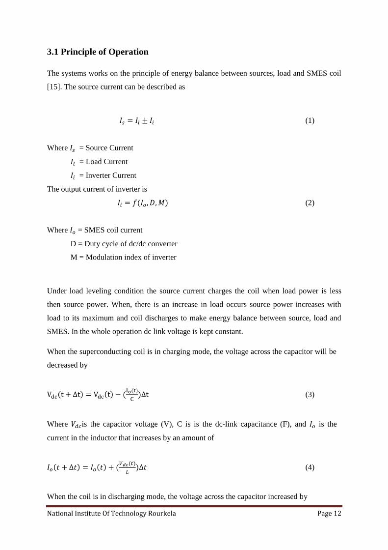
3.1 Principle of Operation
The systems works on the principle of energy balance between sources, load and SMES coil
[15]. The source current can be described as
(1)
Where = Source Current
= Load Current
= Inverter Current
The output current of inverter is
(2)
Where = SMES coil current
D = Duty cycle of dc/dc converter
M = Modulation index of inverter
Under load leveling condition the source current charges the coil when load power is less
then source power. When, there is an increase in load occurs source power increases with
load to its maximum and coil discharges to make energy balance between source, load and
SMES. In the whole operation dc link voltage is kept constant.
When the superconducting coil is in charging mode, the voltage across the capacitor will be
decreased by
(3)
Where is the capacitor voltage (V), C is is the dc-link capacitance (F), and is the
current in the inductor that increases by an amount of
(4)
When the coil is in discharging mode, the voltage across the capacitor increased by

National Institute Of Technology Rourkela Page 13
(5)
And current in the inductor reduces up to
(6)
Similarly, in the inverter side, the function of the hysteresis controller to control the value of
ac source current so as to modify the effective value of capacitor voltage in the following
fashion. When current builds up, i.e., source current increases toward the upper-limit
(7)
The capacitor voltage will be build up as
(8)
In the same manner, when the upper limit is reached, the current will now start to fall toward
the lower limit; the value of the source current then becomes
(9)
And capacitor voltage will be reduced up to
(10)
The exchange of power in load leveling condition is represented in [fig 3.1]. Under load
leveling condition the source current charges the coil when load power is less then source
power. When, there is an increase in load occurs source power increases with load to its
maximum and coil discharges to make energy balance between source, load and SMES. In
the whole operation dc link voltage is kept constant.

National Institute Of Technology Rourkela Page 14
Figure 3.1: PCS operation under Load Leveling
3.2 System Topology:
The topology of the system which is being studied is presented in [fig 3.2.1]. It consists of a
supply network with a source supplying a nonlinear load and SMES is synchronized with the
network with the help of Power Conditioning system (PCS) at the PCC. According the
configuration of PCS, SMES is broadly classified into two types viz: CSC based SMES and
VSC based SMES.
3.2.1.1 VSC Based SMES
The structural figure of the SMES unit with VSC-based PCS [47], [56], [57] is shown in the
[fig 3.2.1.1] that includes of a star-delta transformer, a basic six-pulse PWM converter with
insulated gate bipolar transistor (IGBT) as the switching device, a two quadrant bidirectional
dc-dc chopper using IGBT, and an inductor as the superconducting coil. The decoupling of
ac/dc converter and the dc-dc bidirectional converter is obtained by a large dc link capacitor.
A power electronic link between the ac supply network and the dc current controlled
superconducting coil is established by the PWM VSC. The reference currents in d-axis and
q-axis are determined by proportional integral (PI) controllers acting on the error between
the actual and reference dc link voltage and the error between the actual and reference
terminal voltage, respectively. Then the voltages in d-axis and q-axis are estimated by the
error between estimated d-q axes currents and their actual detected values and transformed
into abc-quantities to obtain the reference sinusoidal signal. The PWM signal is obtained for
the switching of IGBT by comparing the reference signal obtained from abc conversion with
the high frequency triangular carrier signal. Throughout the operation the dc voltage across
the capacitor is kept at its reference value by the six-pulse PWM converter [48], [49], [50],
and [55].

National Institute Of Technology Rourkela Page 15
Figure 3.2.1.1: Power Conditioning System using Voltage Source Converter
A voltage bidirectional dc-dc chopper is used to regulate the charge-discharge of the
superconducting coil. The dc-dc chopper is controlled to make the voltage across SMES coil
such as positive (IGBTs are switched ON) or negative (IGBTs are switched OFF) and then
the energy reserved in SMES can be supplied or consumed accordingly. Hence, the charging
and discharging of superconducting coil depends on the average voltage per cycle across the
coil that is calculated by the duty cycle of the two-quadrant chopper. In order to obtain the
PWM gate pulses for the IGBTs of the dc/dc converter, the estimated signal is compared with
the triangular/saw-toothed carrier signal [58].
3.2.1.2 CSC-Based SMES
The basic topology of the CSC-based SMES unit is shown in [fig: 3.2.1.2]. The ac side of
CSC is interfaced to the supply power lines but dc side is directly connected with the
superconducting coil. At CSC input terminal, a bank of capacitors are connected to mitigate
the reserved energy in inductances of transmission lines by commutating the direction of the
current flowing. Moreover, the capacitors can act as a buffer to eliminate the harmonics of
high-order in the ac line current. An advantage of CSC is that by modulating the triggering
pulses of the switching devices, suitable PWM currents in all the three phases can be
generated which is directly controlled by dc current flowing in SMES. Practically the SMES
system is an inherent current controlled system, which leads to very spontaneous exchange
of both real and reactive powers among the CSC and supply grid [59].

National Institute Of Technology Rourkela Page 16
Figure 3.2.1.2: Power Conditioning System using Current Source Converter
In case of SMES using twelve-pulse CSC, to decrease the total harmonics distortion (THD)
of the source currents, a more appropriate PWM switching scheme is adopted to minimize
the 5th, 7th, 11th, and 13th harmonics. By varying the modulation index between 0.2 and 1,
the 5th, 7th, 11th, and 13th harmonics can be eliminated [60]. In comparison to a six-pulse
CSC, voltage ripples on the dc side in case of the twelve-pulse CSC is smaller, which means
a further minimization of the ac losses in the SMES coil.
The comparison between VSC based SMES and CSC based SMES in various prospective is
enlisted in the [table 3.2.1] given below.

National Institute Of Technology Rourkela Page 17
Criteria VSC based CSC based
Real and
Reactive
Power
In this case, independent control of
real and reactive power flowing
between supply network and SMES
is possible. It can also supply rated
reactive power even at less or no
coil current.
Here, control of real and reactive power
flowing between supply network and
SMES is independent. It can also supply
high level of reactive power, but the
reactive power is dependent on coil
current.
Control
structure
As the VSC based PCS consists of
not only an AC/DC but also a
DC/DC converter, the control is
quite complicated than that of CSC
based PCS.
CSC based PCS consists of only one
AC/DC converter, hence easier to
control. It has an additional advantage
when used in high power circuit, of
being paralleled in multiple stages.
THD low low
Coil
voltage
ripple
There appears ripple in coil voltage
when used in VSC topology.
Ripple across coil voltage is low
especially in twelve-pulse one. This
implies a reduction in the
superconducting coil ac losses.
Table 3.2.1: Comparison between VSC and CSC based Power Conditioning System
Figure 3.2.1: Proposed System Topology

National Institute Of Technology Rourkela Page 18
Here, the PCS consists of a VSC and A DC/DC converter [fig 3.2.1] to control the source
current as well as the charge-discharge cycle of SMES. DC/DC converter is a simple voltage
bidirectional converter consists of IGBTs and diodes as shown in the [fig 3.2.2]. When the
switches are ‘ON’ SMES coil gets charged and positive voltage is applied on it; when they
are ‘OFF’ negative voltage is applied on it and it discharges through diode. In both modes
current remains unidirectional. During standby condition one of the switches is ‘ON’ and
current circulates between that switch and one diode. The switching of this is regulated to get
a constant dc-link voltage. Here, VSC is a six-pulse conventional full bridge converter.
IGBT anti-parallel with a diode is used as the switch to get bidirectional current. It is
controlled to operate in both rectifying and inverting modes which is described later in this
paper.
3.2.2 DC/DC Converter
The prime function of the DC-DC chopper is to control the energy flow through the SMES
coil; that is the charge-discharge cycle of SMES. During the charging period of SMES, the
chopper connects the DC link voltage to the SMES so that the current inside the SMES
increases making power flow from the DC link towards the SMES coil. When the SMES
needs to be discharged, the chopper connects the SMES with the DC link voltage but with
opposite polarity, so that direction of power flow can be changed. The rate of
charge/discharge is regulated by the magnitude and direction of voltage across the SMES
coil. In other words, a variable voltage is applied across the SMES coil by the DC-DC
chopper to make the desired energy flow in or out of the storage device. A detailed
configuration of the two quadrant chopper is represented in [fig 3.2.2]. The different modes
of operation of a chopper are described below.
As shown in [fig 3.2.2], when the two IGBTs are triggered simultaneously and the diodes
become reverse-biased, current flows from source to SMES coil and a positive voltage is
applied across it. So the coil gets charged. Again, when the two IGBTs are switched off and
the diodes become forward biased, current flows in the same direction through SMES coil but
a negative voltage is applied across it. Hence, the coil discharges. The applied voltage across
the SMES coil is controlled by regulating the conduction time of the IGBT over the switching

National Institute Of Technology Rourkela Page 19
cycle. While the duty cycle is 0.5, average voltage across the SMES coil and average DC
current in the VSC are both zero, and net power transferred throughout one complete
switching cycle is zero. For a duty cycle larger than 0.5, the coil gets charged; while at less
than 0.5, the coil gets discharged. Therefore, the control of charge/discharge is established by
regulating the duty cycle of the switching devices.
The amount of switching and ripples can be reduced by some modifications in the operation
of the chopper as follows. When the SMES is not connected to the grid and it stores energy
for future references, either one of the IGBTs needs to be turned on to make a short current
path with one of the diodes. When only IGBT1 is turned on, current flows through D1 and
IGBT1 and voltage across SMES coil is zero (due to short circuit). During this interval, the
dc-link capacitor and the SMES coil are disconnected by the IGBT2 and D2 and energy
stored remains almost constant as power transfer between source and SMES coil is zero.
When the SMES needs to be charged, both of the IGBTs need to be turned on. By doing this,
the capacitor voltage is applied to the SMES coil and charges it. When the SMES needs to be
discharged, both of the IGBTs need to be turned off. During this time, the current flows
through the diodes, charging the capacitor.
Figure 3.2.2: Two quadrant voltage bidirectional DC/DC converter

CHAPTER IV
1. Control Strategy
2. Hysteresis Controller
3. Fuzzy Logic Controller

National Institute of Technology Rourkela Page 20
4.1 Hysteresis Band Controller
Several linear as well as nonlinear control techniques are there to control the required
physical quantity that is mostly the current. Different PWM techniques are mostly used where
the reference is compared with a high frequency carrier wave. But Hysteresis controller has
emerged as a robust nonlinear controller which is simple and can be easily implemented.
Other advantages are
(i) Unconditional stability
(ii) Fast dynamic response
(iii) Good accuracy
(iv) Low cost
Despite of these advantages it suffers from several undesirable aspects. The prime factor is
that it produces switching pulses of changing switching frequency. This creates major
problems in designing the input filter and unwanted resonances in the input side and produces
acoustic noise. Another unsatisfactory feature of the conventional hysteresis control is that its
performance is adversely affected by the interference between phase currents, which is
common in three-phase systems with isolated neutral [65]. Several advancements to the
original control structure have been proposed for industrial applications [61]–[63]. Firstly,
phase current decoupling techniques have been developed [61]. In second, fixed switching
frequency has been obtained by a variable width of the hysteresis band as function of the
instantaneous output voltage, dc-link capacitor voltage and coupling inductances [61], [64].
[Fig 4.1] shows the conventional sinusoidal hysteresis band current control technique used
for the control of the source current. It consists of a hysteresis band around the reference
source current. The reference source current is represented as Is* and actual source current is
represented as Is. The hysteresis band current controller determines the pattern of switching
signals of VSC in PCS [67]. The switching logic is formulated as follows:
When is < (is*- HB) upper switch is OFF and lower switch is ON for leg “a”: (SA=l).
When is > (is*+ HB) upper switch is ON and lower switch is OFF for leg “a”: (SA=O).
Similarly, the switching functions for phases B and C are determined using respective
reference and actual currents and hysteresis bandwidth (HB).
The switching frequency of the hysteresis band current control technique described above
depends on how rapidly the current decays from the upper limit of the hysteresis band to the
lower limit of the hysteresis band, or vice versa [66]. The rate of change of the actual source

National Institute of Technology Rourkela Page 21
currents to be controlled determines the switching frequency, therefore the switching
frequency does not settle at a fixed value in the overall switching operation, rather changes
along with the current waveform. Furthermore, the value of line inductance of the power
conditioning system and the dc link capacitor voltage are the main parameters determining
the rate of change of source currents. Capacitor voltage and the line inductances of the whole
configuration are also responsible for the switching frequency of the system.
Figure 4.1: Operation of Hysteresis Band Controller
In this paper both the voltage source converter and DC/DC bidirectional converter are
controlled by simple Hysteresis band controller. It is a nonlinear controller and can be easily
implemented with good accuracy. [Fig: 4.1] shows the controller diagram of VSC which is
intended to control the source current. The error between actual and reference source current
is given as the input to hysteresis controller that generates switching pulses for VSC.
Whenever the error reaches the upper bound of hysteresis band the upper switch becomes
‘OFF’ and when it touches lower bound lower switch becomes ‘ON’.
DC/DC bidirectional converter is a voltage bidirectional converter. The switching is
controlled by hysteresis controller to regulate the dc link voltage. The error between reference
and instantaneous dc link voltage is given as input to hysteresis controller to generate
switching pulses of both the switch.

National Institute of Technology Rourkela Page 22
4.2 Fuzzy Logic Controller
Fuzzy logic controller is a set of linguistic control rules related by the dual concepts of fuzzy
implication and the compositional rule of inference [27]. It is based on human thinking and
decision making quality that uses natural language to define its rules. Actually, it provides an
effective means of enrolling the approximate, inexact nature of the real world. It was first
proposed by L. Zadeh, Professor at University of California in 1965 as away to process
imprecise data. Zadeh thought process behind Fuzzy Logic was “Attempt to mimic human
control logic”. He used fractions, partial membership instead of crisp set, Boolean, true/false.
Then Mamdani and his colleagues got inspired by Zadeh’s seminar paper on linguistic
approach and system analysis based on the theory of Fuzzy sets. Some basic designs of fuzzy
sets and fuzzy operations are given below in [fig: 4.2.1].
Conventional linear controller linearizes the nonlinear system to an approximate model that
does not guarantee satisfactory performance. Non-linear controllers are developed, but they
require accurate mathematical modeling of the system which is a tedious and hard to obtain
for a complex nonlinear system. Hence, fuzzy logic controller is preferred as it does not
require accurate mathematical modeling of the system.
Fuzzy logic controller incorporates four basic things: a fuzzification interface, a knowledge
base, decision making logic and a defuzzification interface [fig 4.2.1].
(i) Fuzzification Interface
It measures the input variables and conducts scale mapping to transfer the range of
input variables into corresponding universe of discourse. After that mapping of
numeric input variables is done to linguistic variables under different fuzzy so that
they appears as different labels of fuzzy sets [fig 4.2.2].
(ii) Knowledge Base
It is composed of ‘data base’ and ‘rule base’ [table 4.2] that contains linguistic
variables to define control policies and set of control rules. The control rules are
completely based on the behavior of physical system and process to be controlled.
(iii) Decision Making Logic
It is the key member that performs fuzzy implication by inferring fuzzy control
rules. It has the ability of simulating human decision making quality based on
fuzzy concept.

National Institute of Technology Rourkela Page 23
(iv) Defuzzification
It performs a scale mapping which maps the fuzzy output variables to the
corresponding universe of discourse.
Figure 4.2.1: Block Diagram of Fuzzy Logic Controller
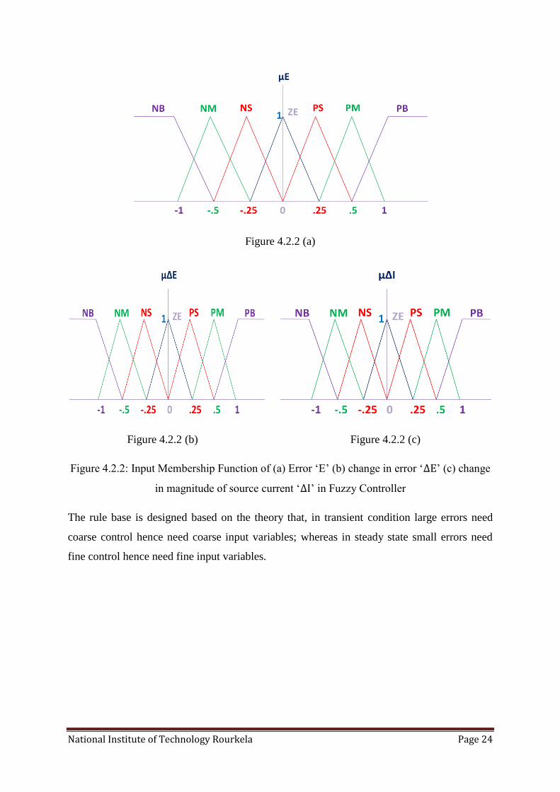
Here, a two input one output Fuzzy Logic controller with 49 rules is implemented. Error and
change in error between the actual and reference SMES energy are taken as input and change
in magnitude of reference current is taken as output. Seven fuzzy sets: Negative Large (NL),
Negative medium (NM), Negative small (NS), zero (ZE), Positive small (PS), Positive
medium (PM), Positive large (PL) are chosen to map each input variables. Triangular
membership function is used for its simplicity. Fuzzification is done in continuous universe
of discourse and defuzzification using ‘Centriod Method’. Mamdani’s ‘min’ operator is
adopted for fuzzy implication.
National Institute of Technology Rourkela Page 24
Figure 4.2.2 (a)
Figure 4.2.2 (b) Figure 4.2.2 (c)
Figure 4.2.2: Input Membership Function of (a) Error ‘E’ (b) change in error ‘ ’ (c) change
in magnitude of source current ‘ ’ in Fuzzy Controller
The rule base is designed based on the theory that, in transient condition large errors need
coarse control hence need coarse input variables; whereas in steady state small errors need
fine control hence need fine input variables.

National Institute of Technology Rourkela Page 25
E
NL NM NS ZE PS PM PL
NL NL NL NL NL NM NS ZE
NM NL NL NL NM NS ZE PS
NS NL NL NM NS ZE PS PM
ZE NL NM NS ZE PS PM PL
PS NM NS ZE PS PM PL PL
PM NS ZE PS PM PL PL PL
PL ZE PS PM PL PL PL PL
Table 4.2: Rule Base of Fuzzy Logic controller
4.3 Control Strategy
The SMES is controlled for load leveling and current-harmonics filtration operations. It is a
constant dc current source that is controlled to meet the required demand of real and reactive
power independently as well as simultaneously. The amount of energy received by SMES
depends directly on the magnitude source current and energy delivered depends on load
dynamics. When, source current increase current in SMES also increases and it gets charged;
when source current decrease SMES current decrease and it discharges. As the source current
is kept in phase with the line to neutral source voltage, the reactive power demand of the load
is always supported by SMES. But the active power delivered by SMES depends on the
capacity of source and load requirement. Under off-load period source supplies power to load
as well as the SMES so that the coil gets charged. In peak-load hour source current increases
with the increase in load up to its maximum value and the additional active power demand is
supported by SMES as it discharges. After charging the current in the coil remains constant at
its rated value, called standby period where no energy is consumed or delivered by the coil
except the loss due to circulating current.

National Institute of Technology Rourkela Page 26
Figure 4.3.1: Proposed control strategy
To control the SMES energy during charging and discharging a Fuzzy Logic Controller is
used. It maintains the SMES instantaneous energy at its reference value. Previously, PI
controller was used for this purpose. But PI controller gives poor performance in systems
having nonlinearity while tuning its gain parameters due to lack of proper understanding
about the system parameters. Hence, fuzzy logic controller has been introduced in this thesis
to get better performance. It has been proved that fuzzy Logic controller has fast response,
small overshoot and better stability in comparison to PI controller. Also design of controller
is less complex in FLC as it requires precise modeling rather exact mathematical modeling of
the system. The error in actual and reference SMES energy is fed to FLC to get change in
magnitude of reference source current as the output as represented in [fig 4.3.2].

National Institute of Technology Rourkela Page 27
Figure 4.3.2: Proposed Fuzzy Controller
This magnitude of reference source current is then multiplied with the unit vector of line to
neutral source voltage to get reference source current. Error in actual and reference source
current is then compared and fed to hysteresis controller to obtain switching pulses for IGBTs
of VSC [fig 4.3.3]. To make the dc-link voltage constant, instantaneous dc-link voltage is
compared with reference dc-link voltage and fed to hysteresis band controller of a tolerance
limit of 0.1%.
Figure 4.3.3: Switching pulses Generation for VSC

CHAPTER V
1.Simulation Results
2.Conclusion and Discussion
3.Future Scope
4.References
National Institute of Technology Rourkela Page 28
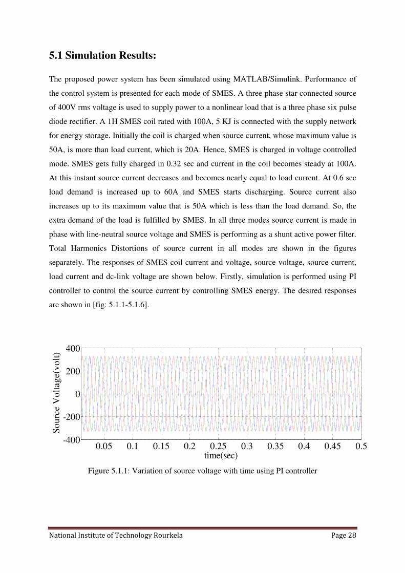
5.1 Simulation Results:
The proposed power system has been simulated using MATLAB/Simulink. Performance of
the control system is presented for each mode of SMES. A three phase star connected source
of 400V rms voltage is used to supply power to a nonlinear load that is a three phase six pulse
diode rectifier. A 1H SMES coil rated with 100A, 5 KJ is connected with the supply network
for energy storage. Initially the coil is charged when source current, whose maximum value is
50A, is more than load current, which is 20A. Hence, SMES is charged in voltage controlled
mode. SMES gets fully charged in 0.32 sec and current in the coil becomes steady at 100A.
At this instant source current decreases and becomes nearly equal to load current. At 0.6 sec
load demand is increased up to 60A and SMES starts discharging. Source current also
increases up to its maximum value that is 50A which is less than the load demand. So, the
extra demand of the load is fulfilled by SMES. In all three modes source current is made in
phase with line-neutral source voltage and SMES is performing as a shunt active power filter.
Total Harmonics Distortions of source current in all modes are shown in the figures
separately. The responses of SMES coil current and voltage, source voltage, source current,
load current and dc-link voltage are shown below. Firstly, simulation is performed using PI
controller to control the source current by controlling SMES energy. The desired responses
are shown in [fig: 5.1.1-5.1.6].
Figure 5.1.1: Variation of source voltage with time using PI controller
0.05 0.1 0.15 0.2 0.25 0.3 0.35 0.4 0.45 0.5-400
-200
0
200
400
time(sec)
So
urc
e V
olt
ag
e(v
olt
)

National Institute of Technology Rourkela Page 29
Figure 5.1.2: Variation of load current with time. At 0.6 sec there occurs a change in load
which increases the load current
Figure 5.1.3: Variation of source currents in all the phases with time using PI controller. At
0.32 sec it decreases as the coil gets fully charged and at 0.6 sec it reaches its maximum when
load demand increases
Figure 5.1.4: Variation of source current in one phase with time
0.1 0.2 0.3 0.4 0.5 0.6 0.7 0.8 0.9 1-100
-50
0
50
100
time(sec)
Lo
ad
Cu
rren
t(am
p)
0.1 0.2 0.3 0.4 0.5 0.6 0.7
-50
0
50
time(sec)
Sourc
e C
urr
ent(
amp)
0.1 0.2 0.3 0.4 0.5 0.6 0.7 0.8 0.9 1-100
-50
0
50
100
time(sec)
Sou
rce
curr
ent(
am
p)

National Institute of Technology Rourkela Page 30
Figure 5.1.5: Variation of SMES coil current with time using PI controller. At 0.32 sec SMES
coil gets fully charged with current 100A and it discharges at 0.6 sec when load current
increases
Figure 5.1.6: Variation of dc-link voltage with time using Hysteresis controller. It is
maintained constant throughout the whole operation of SMES
The results obtained using PI controller is not fully satisfactory as the THD in source current
is more than 5% in stand-by and discharging modes of operation. To reduce the THD less
than 5% Fuzzy logic controller is used in place of PI controller. The results obtained using
FLC are as follows in [fig: 5.1.7-5.1.12].
0 0.1 0.2 0.3 0.4 0.5 0.6 0.7 0.8 0.9 1
0
50
100
150
time(sec)
SM
ES
Coil
Curr
ent(
am
p)
0.1 0.2 0.3 0.4 0.5 0.6 0.7 0.8 0.9 10
500
1000
time(sec)
DC
-lin
k V
oltag
e(v
olt)
National Institute of Technology Rourkela Page 31
Figure 5.1.7: Variation of source voltage with time using Fuzzy logic controller
Figure 5.1.8: Variation of load current with time. At 0.6 sec there occurs a change in load
which increases the load current
Figure 5.1.9: Variation of source currents in all the phases with time using Fuzzy controller.
At 0.32 sec it decreases as the coil gets fully charged and at 0.6 sec it reaches its maximum
when load demand increases.
0.05 0.1 0.15 0.2 0.25 0.3 0.35 0.4 0.45 0.5-400
-200
0
200
400
time(sec)
Sourc
e V
oltag
e(v
olt)
0.1 0.2 0.3 0.4 0.5 0.6 0.7 0.8 0.9 1-100
-50
0
50
100
time(sec)
Load C
urr
ent(
am
p)
0.1 0.2 0.3 0.4 0.5 0.6 0.7-100
-50
0
50
100
time(sec)
Sourc
e C
urr
ent(
amp)

National Institute of Technology Rourkela Page 32
Figure 5.1.10: Variation of source current in one phase with time
Figure 5.1.11: Variation of SMES coil current with time using fuzzy controller. At 0.32 sec
SMES coil gets fully charged with current 100A and it discharges at 0.6 sec when load
current increases.
Figure 5.1.12: Variation of dc-link voltage with time using Hysteresis controller. It is
maintained constant throughout the whole operation of SMES and same as obtained in PI
controller.
0.1 0.2 0.3 0.4 0.5 0.6 0.7 0.8 0.9 1-100
-50
0
50
100
time(sec)
Sourc
e C
urr
ent(am
p)
0 0.1 0.2 0.3 0.4 0.5 0.6 0.7 0.8 0.9 1
0
50
100
150
time(sec)
SM
ES C
oil C
urr
ent(
am
p)
0.1 0.2 0.3 0.4 0.5 0.6 0.7 0.8 0.9 10
500
1000
time(sec)
DC
-lin
k V
olt
ag
e(v
olt
)

National Institute of Technology Rourkela Page 33
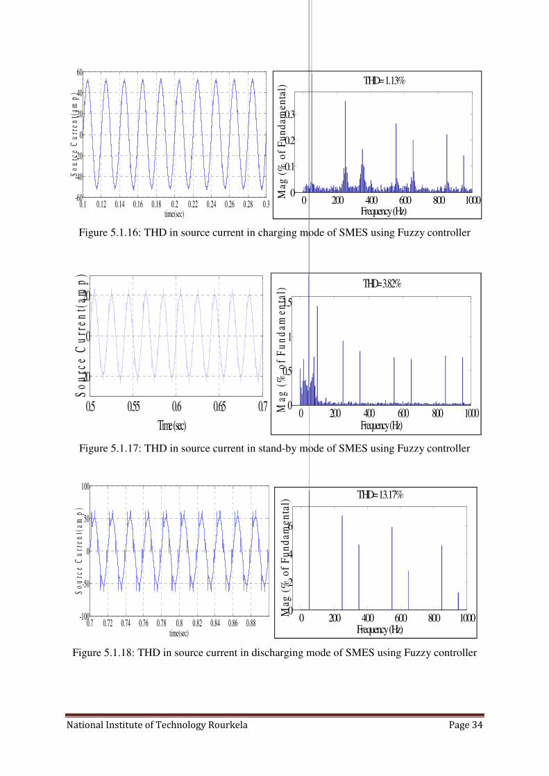
The source currents in charging, stand-by and discharging mode of SMES obtained using PI
and Fuzzy controller are analyzed and their THD were estimated. Below are the [fig: 5.1.13-
5.1.18] and their THD counts.
Figure 5.1.13: THD in source current in charging mode of SMES using PI controller
Figure 5.1.14: THD in source current in stand-by mode of SMES using PI controller
Figure 5.1.15: THD in source current in discharging mode of SMES using PI controller
0.1 0.12 0.14 0.16 0.18 0.2 0.22 0.24 0.26 0.28 0.3-60
-40
-20
0
20
40
60
time(sec)
So
urc
e C
urr
ent(
amp
)
0 200 400 600 800 10000
0.1
0.2
0.3
0.4
Frequency (Hz)
THD= 1.26%
Ma
g (
% o
f F
un
da
me
nta
l)
0.4 0.42 0.44 0.46 0.48 0.5 0.52 0.54 0.56 0.58 0.6-30
-20
-10
0
10
20
30
time(sec)
So
urc
e C
urr
en
t(am
p)
0 200 400 600 800 10000
2
4
6
Frequency (Hz)
THD= 10.58%
Ma
g (
% o
f F
un
da
me
nta
l)
0.7 0.72 0.74 0.76 0.78 0.8 0.82 0.84 0.86 0.88-100
-50
0
50
100
time(sec)
So
urc
e C
urr
en
t(a
mp
)
0 200 400 600 800 10000
2
4
6
Frequency (Hz)
THD= 13.51%
Ma
g (
% o
f F
un
da
me
nta
l)
National Institute of Technology Rourkela Page 34
Figure 5.1.16: THD in source current in charging mode of SMES using Fuzzy controller
Figure 5.1.17: THD in source current in stand-by mode of SMES using Fuzzy controller
Figure 5.1.18: THD in source current in discharging mode of SMES using Fuzzy controller
0.1 0.12 0.14 0.16 0.18 0.2 0.22 0.24 0.26 0.28 0.3-60
-40
-20
0
20
40
60
time(sec)
So
urc
e C
urr
en
t(am
p)
0 200 400 600 800 10000
0.1
0.2
0.3
Frequency (Hz)
THD= 1.13%
Ma
g (
% o
f F
un
da
me
nta
l)
0.5 0.55 0.6 0.65 0.7
-20
0
20
Time (sec)
So
urc
e C
urr
en
t(a
mp
)
0 200 400 600 800 10000
0.5
1
1.5
Frequency (Hz)
THD= 3.82%M
ag
(%
of
Fu
nd
amen
tal)
0.7 0.72 0.74 0.76 0.78 0.8 0.82 0.84 0.86 0.88-100
-50
0
50
100
time(sec)
So
urc
e C
urr
en
t(a
mp
)
0 200 400 600 800 10000
2
4
6
Frequency (Hz)
THD= 13.17%
Mag
(%
of
Fu
nd
ame
nta
l)

National Institute of Technology Rourkela Page 35
The performance in terms of THD count of both PI and Fuzzy controllers are compared and
enlisted in the following [table: 5.1].
MODE OF operation of
SMES
THD obtained in source
current using PI controller
THD obtained in source
current using Fuzzy controller
Charging 1.26 % 1.13 %
Standby 10.58 % 3.82 %
Discharging 13.51 % 13.17 %
Table 5.1: Comparison of THD between PI and Fuzzy controller in different modes of
operation of SMES
5.2 Conclusion and Discussion
In the above results and analysis it has shown that the complete cycle of SMES that is
charging, stand by and discharging can be controlled along with the sinusoidal nature of
source current irrespective of load conditions by using both PI and Fuzzy logic controller.
Then the results were compared from which it can be shown that the THD obtained in case of
Fuzzy controller is less. In case of charging mode of SMES using both PI and Fuzzy
controllers THD are below IEEE standard, which is 5%. But during standby mode THD using
PI controller is much more than Fuzzy controller and THD in Fuzzy controller is within 5%.
It is because of steady state error in SMES energy response introduced by PI controller. The
response of SMES energy in PI controller settles quickly, within one cycle and hence the
source current changes its magnitude from 50A to 20A, without any undershoot. The
dynamic response of PI controller is better but due to steady state error its THD count is
more. In case of Fuzzy controller, response of SMES energy takes 2-3 cycles to settles at its
reference value. Therefore source current changes its magnitude from 50A to 20A after
completion of charging cycle after undergoing overshoot and undershoot but the %age of
overshoot and undershoot are within 5% (IEEE standard). During discharging operation of
SMES, THD in source current is nearly same in both the controllers which is more than 5%
and highly undesirable.
The discussion above finally concludes that, overall performance of Fuzzy Logic controller is
satisfactory and better than that of PI controller. Though the harmonics elimination operation

National Institute of Technology Rourkela Page 36
of SMES using Fuzzy controller is unsatisfactory in discharging mode, but load leveling, the
primary function of SMES is obtained quite satisfactorily.
5.3 Future Scope
The THD in discharging mode can be lowered by a better design of fuzzy controller using
optimization techniques to make an adaptive Fuzzy system. The range of membership
function of input variables in Fuzzy controller can also be optimized to get more accuracy.
Due to Hysteresis controller the switching frequency of IGBT is not constant and varies at
each instant. This problem can be avoided by the use of Adaptive hysteresis controller in
which the switching frequency is kept constant and the hysteresis band is varied accordingly.
Further improvements can be done by increasing the level of DC/DC converter and
controlling its switching using PWM controller so that harmonics can be minimized.

National Institute of Technology Rourkela Page 37
Reference
[1] W. V. Torre and S. Eckroad, “Improving power delivery through the application of superconducting
magnetic energy storage (SMES),” in Proc. IEEE Power Eng. Soc. Winter Meeting, vol. 1, 2001, pp. 81–87.
[2] I. D. Hassan, R. M. Bucci, and K. T. Swe, “400 MW SMES power conditioning system part-1 performance
requirement and configuration,” IEEE Conference on Power Electronics Specialists Jun 1991 page no: 338-344.
[3] D. Casadei, G. Grandi, U. Reggiani, and G. Serra, “Analysis of a power conditioning system for
superconducting magnetic energy storage (SMES),” in Proc. IEEE Int. Symp. Industrial Electronics (ISIE’98),
vol. 2, 1998, pp. 546–551.
[4] Mohd. Hasan Ali, Bin Wu and Roger A. Dougal, “An Overview of SMES Applications in Power and
Energy Systems,” IEEE Transactions on Sustainable Energy, vol. 1, no. 1, April 2010
[5] Q. Yao and D. G. Holmes, “A simple, novel method for variable-hysteresis- band current control of a three
phase inverter with constant switching frequency,” in Proc. Industry Applications Soc. Annu. Meeting, vol. 2,
1993, pp. 1122–1129.
[6] M. Lafoz, I. J. Iglesias, C. Veganzones, and M. Visiers, “A novel double hysteresis band control for a three
level voltage source inverter,” in Proc. IEEE 31st Ann. Power Electronics Specialists Conf. (PESC). , vol. 1,
2000, pp. 21–26.
[7] O. L. Gyugyi, E.C.Strycula, “Active AC Power Filter,” Proc. IEEE-IAS
[8] H.Akagi, Y.Kanazawa, A.Nabae, “Instantaneous Reactive Power Annual Meeting, pp. 529, 1976.
Compensators Comprising Switching Devices without Energy Storage Components,” IEEE Trans. on IA, Vol.
20, pp. 625, 1984.
[9] L.Malesani, L.Rossetto, P.Tenti, “Active Filters for Reactive Power and Harmonic Compensation,” Proc.
IEEE-PESC, pp. 321-330, June 1986.
[10] 0. Simon, H. Spaeth, K.P. Juengst, P. Komarek, “Experimental Setup of a Shunt Active Filter Using a
Superconducting Magnetic Energy Storage Device,” Proc. EPE97, Vol.1, pp. 447-452, September 1997.
[11] R W Boom and H A Peterson, “Superconductive Energy Storage for Power Systems”. IEEE Trans.
Magnetics, MAG-8, No. 3, pp 701 -703, 1972
[12] J D Rogers etal. “30-MJ Superconducting Magnetic Energy Storage System for Electric Utility
Transmission Stabilization”, Proc. IEEE, Vol. 71, NO. 9,pp 1099-1107.1983
[13] SMSchoenung, W. V. Hassenzahl and P. G. Filios, “US Program to Develop Superconducting Magnetic
Energy Storage.” Proc. of 23rd Inter Society Energy Conversion Engineering Conference Vol. 2, pp
537440,1988.
[14] D. Casadei, G. Grandi, U. Reggiani, and G. Serra, “Analysis of a power conditioning system for
superconducting magnetic energy storage (SMES),” in Proc. IEEE Int. Symp. Industrial Electronics (ISIE’98),
vol. 2, 1998, pp. 546–551.
[15] Mohan V. Aware and Danny Sutanto, “Improved Controller for Power Conditioner Using High-
Temperature Superconducting Magnetic Energy Storage (HTS-SMES), ” Proc. IEEE transactions on Applied
Superconductivity, vol. 13, no. 1, march 2003
[16] L. A. Zadeh, “Fuzzy sets,” Informat. Control, vol. 8. pp. 338-353. 1965.
[17] E. H. Mamdani, “Applications of fuzzy algorithms for simple dynamic plant.” Proc. IEE, vol. 121. no. 12.
pp. 1585-1588. 1974.
[18]E. H. Mamdani and S. Assilian. ”An experiment in linguistic synthesis with a fuzzy logic controller,” Int. J .
Mun Much. Stutlies. vol. 7, no I , pp. 1-13. 1975.
[19] E. H. Mamdani, “Advances in the linguistic synthesis of fuzzy controllers,” Int. J . Man Mach. Studies. vol.
8, no. 6, pp. 669-678, 1976.
[20] E. H. Mamdani, “Application of fuzzy logic to approximate reasoning using linguistic synthesis,” IEEE
Trans. Computer, vol. C-26, no. 12, pp. 1182-1 191. 1977
[21] P. J. King and E. H. Mamdani, “The application of fuzzy control systems to industrial processes,”
Automat., vol. 13, no. 3, pp. 235-242, 1977.
[22] L. A. Zadeh, “Fuzzy algorithm,” Informat. Control, vol. 12, pp. 94-102, 1968
[23] R. E. Kalman and N. DeClaris. Ed. New York: Holt, Rinehart and Winston, “towards a theory of Fuzzy
Systems,” in Aspect of Network and System Theory, 1971, pp. 469-490.

National Institute of Technology Rourkela Page 38
[24] L. A. Zadeh, “Similarity relations and fuzzy orderings,” Infomat. Sci, vol. 3. Issue 2. pp. 177-200
[25] L. A. Zadeh, “A rationale for fuzzy control,” Trans. ASME, J. Dynam. Syst. Measur. Control, vol. 94. pp. 3-
4, 1972.
[26] L. A. Zadeh, “Outline of a new approach to the analysis complex systems and decision processes,” IEEE
Trans. Syst. Man Cybem., vol. SMC-3, pp. 28-44, 1973
[27] C. C. Lee’ “Fuzzy Logic in Control Systems: Fuzzy Logic Controller-Part I,” lEEE transactions on system,
man and cybernetics. vol. 20. no. 2. makc'kl/apkii. 1990
[28]“IEEE task force on benchmark models for digital simulation of FACTS and custom—Power controllers,
T&D committee, detailed modeling of superconducting magnetic energy storage (SMES) system,” IEEE Trans.
Power Del., vol. 21, no. 2, pp. 699–710, Apr. 2006.
[29] C. A. Luongo, “Superconducting storage systems: An overview,” IEEE Trans. Magn., vol. 32, no. 4, pp.
2214–2223, Jul. 1996.
[30] V. Karasik, K. Dixon, C.Weber, B. Batchelder, G. Campbell, and P. F. Ribeiro, “SMES for power utility
applications: A review of technical and cost considerations,” IEEE Trans. Appl. Supercond., vol. 9, no. 2, pp.
541–546, Jun. 1999.
[31] P. D. Baumann, “Energy conservation and environmental benefits that may be realized from
superconducting magnetic energy storage,” IEEE Trans. Energy Convers., vol. 7, no. 2, pp. 253–259, Jun. 1992.
[32] C.-H. Hsu and W. J. Lee, “Superconducting magnetic energy storage for power system applications,” IEEE
Trans. Industry Applicat., vol. 29, no. 5, pp. 990–996, Sep./Oct. 1992.
[33] W. E. Buckles, M. A. Daugherty, B. R.Weber, and E. L.Kostecki, “The SSD: A commercial application of
magnetic energy storage,” IEEE Trans. Appl. Supercond., vol. 3, no. 1, pp. 328–331, Mar. 1993.
[34] X. D. Xue, K. W. E. Cheng, and D. Sutanto, “Power system applications of superconducting magnetic
energy storage systems,” in IEEE Ind. Applications Conf. 2005, Oct. 2005, vol. 2, pp. 1524–1529.
[35] W. V. Torre and S. Eckroad, “Improving power delivery through the application of superconducting
magnetic energy storage (SMES),” in Proc. IEEE Power Engineering Society Winter Meeting, 2001, pp. 81–87.
[36] I. Ngamroo, C. Taeratanachai, S. Dechanupaprittha, and Y. Mitani, “Enhancement of load frequency
stabilization effect of superconducting magnetic energy storage by static synchronous series compensator based
on control,” Energy Convers. Manage., vol. 48, no. 4, pp. 1302–1312, Apr. 2007.
[37] P. F. Ribiero, B. K. Johnson, M. L. Crow, A. Arsoy, and Y. Liu, “Energy storage systems for advanced
power applications,” Proc. IEEE, vol. 89, no. 12, pp. 1744–1756, Dec. 2001.
[38] X. D. Xue, K. W. E. Cheng, and D. Sutanto, “A study of the status and future of superconducting magnetic
energy storage in power systems,” Supercond. Sci. Technol., vol. 19, pp. R31–R39, 2006.
[39] S. Suzuki, J. Baba, K. Shutoh, and E. Masada, “Effective application of superconducting magnetic energy
storage (SMES) to load leveling for high speed transportation system,” IEEE Trans. Appl. Supercond., vol. 14,
no. 2, pp. 713–716, Jun. 2004.
[40] M. G. Rabbani, J. B. X. Devotta, and S. Elangovan, “Application of simultaneous active and reactive power
modulation of SMES unit under unequal �-mode for power system stabilization,” IEEE Trans. Power Syst., vol.
14, no. 2, pp. 547–552, May 1999.
[41] Y. Mitani and K. Tsuji, “Power system stabilization by superconducting magnetic energy storage connected
to rotating exciter,” IEEE Trans. Appl. Supercond., vol. 3, no. 1, pp. 219–222, Mar. 1993.
[42] C. J. Wu and C.-F. Lu, “Damping torsional oscillations by a superconducting magnetic energy storage
unit,” Elect. Mach. Power Syst., vol. 22, no. 1, pp. 1–15, Jan./Feb. 1994.
[43] L. Wang, S. M. Lee, and C. L. Huang, “Damping sub synchronous resonance using superconducting
magnetic energy storage unit,” IEEE Trans. Energy Convers., vol. 9, no. 4, pp. 770–777, Dec. 1994.
[44] O. Wasynczuk, “Damping sub synchronous resonance using energy storage,” IEEE Trans. Power App.
Syst., vol. PAS-101, no. 4, pp. 905–913, Apr. 1982.
[45] A. H. M. A. Rahim, A. M. Mohammad, and M. R. Khan, “Control of sub synchronous resonant modes in a
series compensated system through superconducting magnetic energy storage units,” IEEE Trans. Energy
Convers., vol. 11, no. 1, pp. 175–180, Mar. 1996.
[46] F. Zhou, G. Joos, C. Abbey, L. Jiao, and B. T. Ooi, “Use of large capacity SMES to improve the power
quality and stability of wind farms,” in Proc. IEEE Power Engineering Society General Meeting, 2004, Jun.
2004, vol. 2, pp. 2025–2030.

National Institute of Technology Rourkela Page 39
[47] M. H. Ali, T. Murata, and J. Tamura, “A fuzzy logic-controlled SMES for damping shaft torsional
oscillations of synchronous generator,” IEEJ Trans. Elect. Electron. Eng., vol. 1, pp. 116–120, May 2006,
Wiley.
[48] T. Kinjo, T. Senjyu, N. Urasaki, and H. Fujita, “Terminal-voltage and output-power regulation of wind-
turbine generator by series and parallel compensation using SMES,” IEE Proc. Gener. Trans. Distrib., vol. 153,
no. 3, pp. 276–282, May 2006.
[49] M. H. Ali, T. Murata, and J. Tamura, “Minimization of fluctuations of line power and terminal voltage of
wind generator by fuzzy logic-controlled SMES,” Int. Rev. Elect. Eng. (IREE), vol. 1, no. 4, pp. 559–566, Oct.
2006.
[50] M. H. Ali, M. Park, I.-K. Yu, T. Murata, and J. Tamura, “Improvement of wind generator stability by fuzzy
logic-controlled SMES,” in Proc. Int. Conf. Electrical Machines and Systems 2007 (ICEMS 2007), Oct. 08–11,
2007, pp. 1753–1758.
[51] T. Asao, R. Takahashi, T. Murata, J. Tamura, M. Kubo, A. Kuwayama, and T. Matsumoto, “Smoothing
control of wind power generator output by superconducting magnetic energy storage system,” in Proc. Int. Conf.
Electrical Machines and Systems 2007 (ICEMS 2007), Oct. 08–11, 2007, pp. 302–307.
[52] P. Tixador, “Superconducting magnetic energy storage: Status and perspective,” IEEE/CSC & ESAS Eur.
Supercond. News Forum, no. 3, Jan. 2008.
[53] I. Ngamroo, A. N. C. Supriyadi, S. Dechanupaprittha, and Y. Mitani, “Power oscillation suppression by
robust SMES in power system with large wind power penetration,” J. Physica C, Supercond., vol. 469, no. 1,
pp. 44–51, Jan. 2009.
[54] M. H. Ali, T. Murata, and J. Tamura, “A fuzzy logic-controlled superconducting magnetic energy storage
(SMES) for transient stability augmentation,” IEEE Trans. Control Syst. Technol., vol. 15, no. 1, pp. 144–150,
Jan. 2007.
[55] M. H. Ali, T. Murata, and J. Tamura, “Transient stability enhancement by fuzzy logic-controlled SMES
considering coordination with optimal reclosing of circuit breakers,” IEEE Trans. Power Syst., vol. 23, no. 2,
pp. 631–640, May 2008.
[56] F. Zhou, G. Joos, C. Abbey, L. Jiao, and B. T. Ooi, “Use of large capacity SMES to improve the power
quality and stability of wind farms,” in Proc. IEEE Power Engineering Society General Meeting, 2004, Jun.
2004, vol. 2, pp. 2025–2030.
[57] M. V. Aware and D. Sutanto, “SMES for protection of distributed critical loads,” IEEE Trans. Power Del.,
vol. 19, no. 3, pp. 1267–1275, Jul. 2004.
[58] A. Tomoki, R. Takahashi, T. Murata, J. Tamura, K. Masahiro, M. Yoshiharu, K. Akira, and M. Takatoshi,
“Evaluation method of power rating and energy capacity of superconducting magnetic energy storage system for
output smoothing control of wind farm,” in 18th
Int. Conf. Electrical Machines (ICEM2008), Portugal, 2008,
Paper ID 1411.
[59] K. Imaie, O. Tsukamoto, and S. Washida, “Control strategies of multiple current-source PWM converters
for a 20 MW SMES system,” IEEJ Trans. Ind. Applicat., vol. 120-D, no. 3, pp. 390–396, Mar. 2000.
[60] X. Jiang, X. Chu, X.Wu,W. Liu, Y. Lai, Z.Wang, Y. Dai, and H. Lan, “SMES system for study on utility
and customer power applications,” IEEE Trans. Appl. Supercond., vol. 11, no. 1, pp. 1765–1768, Mar. 2001.
[61] A. Kawamura and R. G. Hoft, “Instantaneous feedback controlled PWM inverters with adaptive
hysteresis,” IEEE Trans. Ind. Applicat., vol. IA-20, pp. 769–775, July/Aug. 1984.
[62] C. Chiarelli, L. Malesani, S. Pirondini, and P. Tomasin, “Single phase, three-level, constant frequency
current hysteresis control for UPS applications,” in Proc. European Conf. Power Electronics and Applications,
Brighton, U.K., Sept. 1993, pp. 180–185.
[63] L. Malesani and P. Tenti, “A novel hysteresis control method for current controlled VSI PWM inverters
with constant modulation frequency,” IEEE Trans. Ind. Applicat., vol. 26, pp. 88–92, Jan./Feb. 1990.
[64] Q. Yao and D. G. Holmes, “A simple, novel method for variable hysteresis- band current control of a three
phase inverter with constant switching frequency,” in Conf. Rec. IEEE-IAS Annu. Meeting, Toronto, Ont.,
Canada, Oct. 1993, pp. 1122–1129.
[65] Simone Buso, Luigi Malesani and Paolo Mattavelli, “Comparison of Current Control Techniques for
Active Filter Applications,” IEEE Transactions On Industrial Electronics, Vol. 45, No. 5, October 1998
[66] Murat Kale, Engin Ozdemir, ” A Novel Adaptive Hysteresis Band Current Controller for Shunt Active
Power Filter,” in Conf. IEEE on Control Applications, vol.2, pp. 1118-1123, June 2003
[67] B. Singh, K. Haddad, A. Chandra “A new Control Approach to Three-Phase Active Filter for Harmonics
and Reactive Power Compensation,.’ IEEE Transactions on Power System, vo1.n1o3, pp. 133-138, 1998.