study of process parameters towards improving efficiency of...
TRANSCRIPT

I
STUDY OF PROCESS PARAMETERS TOWARDS IMPROVING EFFICIENCY OF CLOSED DIE HOT FORGING PROCESS
A THESIS SUBMITTED IN PARTIAL FULFILMENT OF
THE REQUIREMENT FOR THE AWARD OF THE DEGREE
OF
MASTER OF TECHNOLOGY IN
MECHANICAL ENGINEERING
(SPECIALIZATION IN PRODUCTION ENGINEERING)
BY
CHANDAN SAMAL (ROLL NO. 212ME2474)
NATIONAL INSTITUTE OF TECHNOLOGY ROURKELA
ROURKELA-769008, INDIA
II
National Institute of Technology, Rourkela
C E R T I F I C A T E This is to certify that the dissertation entitled, “Study of Process Parameters
towards Improving Efficiency of Closed Die Hot Forging Process” being submitted
by Chandan Samal to the National Institute of Technology, Rourkela, as a partial
fulfilment of the requirements for the award of the degree of Master of Technology in
Mechanical Engineering (Production Engineering), is a record of bonafide research
work carried out by him during the period July 2013 to May 2014 under our guidance
and supervision.
To the best of our knowledge, this work has not been published/reported or
submitted to any other university or institution for the award of any degree.
------------------------------------ -----------------------------------
Dr. Saurav Datta (Principal Supervisor) Asst. Professor Dept. of Mechanical Engineering National Institute of Technology Rourkela
Dr.- Ing. O.N. Mohanty (Co-Supervisor at Industry) Director, RSB (T & AI Division) Bhubaneswar

III
A C K N O W L E D G E M E N T
This thesis is the outcome of a project work jointly carried out at the National Institute of
Technology (NIT), Rourkela along with Forging Division of RSB Transmissions (I) Ltd. In the
execution of the project, a number of people have contributed in various ways and they deserve
special thanks. It is a pleasure to record my gratitude to all of them.
In the first place, I would like to express my deep sense of indebtedness to both of my
supervisors Prof. S. Datta and Prof. O.N. Mohanty, for their invaluable guidance, motivation,
and above all for their ever co-operating attitude that enabled me in bringing up this report to
the present form.
I am grateful to the Director, Prof. S.K. Sarangi, and Prof. K.P. Maity, Head of Mechanical
Engineering Department, National Institute of Technology, Rourkela, for their kind support and
encouragement from time to time.
A special note of thanks to the Plant Head of RSB Forging Division, Mr. V. Anbarasan and
the development team led by Mr. Sibananda Sahoo, for all the support and help extended
during the experimental part of the project.
Last but not the least, I am thankful to all the staff members of the NIT-Rourkela, to all my
well-wishers and friends for their inspiration and help.
Chandan Samal

IV
A B S T R A C T
Closed die hot forging process is one of the most adopted methods for forming complex
shaped parts with satisfactory geometrical accuracy. Over sixty percent of the forgings are
processed through this route. Forged parts, though required in many engineering sectors, play a
vital role in the automotive sector. The majority of the crucial load bearing structural components
as well as safety critical items are processed via the forging route. This is mainly due to the inherent
strength to weight ratio and dimensional accuracy that can be combined into the components.
Faster production of complex shapes with least wastage of material are some of the other benefits.
The metal flow analysis of the process is complex due to the involvement of a large number
of parameters. A number of experimental testings and production-trials are being done in the
industry in order to develop a robust manufacturing process. Such practices however involve huge
investments in tooling and raw materials, including a great deal of development time and effort. In
recent years, finite element method has emerged as a suitable tool for virtual process trials and
simulation based design. This would lead to an improvement in overall efficiency of the process at
a lower cost.
Through the present study, an attempt has been made to gain an insight into the process
parameters influencing the closed die hot forging and their interaction. As a sample case, a real life
automotive driveline component, a flange yoke, is taken for investigation. A simulation-driven
approach using a commercial package (DEFORM), based on finite element method, was adopted.
Trials were conducted using an industrial press, data generated were validated against those
predicted. The correlation was found to be satisfactory.
-----------------------------------------------------------------------------------------------------------------------------------
Key words: Automotive, Closed die forging, Finite Element Method, Hot forging, Process Parameter

V
CONTENTS
Title Sheet I
Certificate II
Acknowledgement III
Abstract IV
Contents V-VII
List of Tables VIII
List of Figures IX
1. Chapter 1: Introduction 1-9
1.1. Forged Components in Automotive 1
1.2. Closed-die Forging process : An Introduction 3
1.3. Process Variables in Closed-die Hot Forging (CDHF) 3
1.4. Major Factors influencing the Metal Flow 5
1.4.1. Forging Temperature 5
1.4.2. Flow Stress 5
1.4.3. Friction and Lubrication 5
1.4.4. Forgeability of the Material 6
1.4.5. Shape factor of Component and Die 6
1.4.6. Die Temperature 6
1.5. Typical Forged Components in Automotive: A Note 7
1.6. Analysis of Parameters Affecting a Closed Die Forging Process- An Overview 8
1.7. Present Work: Aim and Scope 8
1.8. Outline of the Report 9
2. Chapter 2: Literature Survey 10-17
2.1. Closed Die Forging Process and Process Parameters 10
2.2. Approaches for Analysis of the Closed Die Forging Process 13
2.2.1. Analytical methods 13
2.2.2. Numerical Methods 15
2.3. Finite Element Analysis for CDHF Process 15
2.4. Summary Observations and Directions for Present Work 17
VI
3. Chapter 3: Analysis of Closed Die Hot Forging Process: Use of Relevant Techniques 18-27
3.1. FEM for Analysis of Closed Die Hot Forging Process: A Summary 18
3.2. Description of FE Process for Closed Die Forging 19
3.3. FE Formulation for Metal Flow in Hot Forging 21
3.4. Design by Simulation 23
3.4.1. Purpose of Design by Simulation 23
3.4.2. Precautions in Design by Simulation 23
3.5. Commercial FE-Packages Suitable for Closed Die Forging: Introduction to DEFORM 24
3.5.1. Features of DEFORM Suitable for Closed Die Hot Forging Process 25
3.5.2. Simulation Steps for CDHF process in DEFORM 25
4. Chapter 4: Design Consideration for the Process 28-36
4.1. Product Design Stage 28
4.2. Die Design Stage 30
4.2.1. Determination of Parting line and Axis of Product for Manufacturing 30
4.2.2. Designing the Forging Part 31
4.2.3. Incorporating the Draft Angle in Design 32
4.2.4. Flash and Gutter Design 33
4.2.5. Design consideration for Fillet and Corner radii 33
4.2.6. Deciding the Number of Stages for Forging 34
5. Chapter 5: Experimental Work 37-49
5.1. Determination of Stock/Billet Size for the Experiment 37
5.2. Determination of Flash Land Dimensions 38
5.3. Actual Experimental Setup 39
5.4. Verification and validation of experimental procedure 40
5.5. Stage wise simulation result 44
5.6. Determination of Die Filling during Analysis 46
5.7. Experimental Details Aiming Design of Experiment 47
5.8. Experimental Results 49

VII
6. Chapter 6: Analysis of Experimental Work 50-56
6.1. Data Analysis on Effect of Parameters 50
6.2. Design of Experiment Trial 53
7. Chapter 7: Conclusion and Scope for Future Work 57-58
7.1. Conclusion 57
7.2. Scope for Future Work 58
References 59-60

VIII
List of Tables
Table No. Table Caption Page Number
1.1 Application areas of forged parts in automotive 2
2.1 List of commercial FE software, suitable for analysis of CDHF process 24
5.1 Summarised result of flash thickness calculation 38
5.2 Dimensional validation table for flash width/pattern (Actual/Predicted) 42
5.3 Various input parameters and their levels for the experimentation 48
5.4 Experimental finding of the forging load at different levels of input parameter 49
6.1 L9 Orthogonal array with parameters, response and calculated S/N Ratio 54
6.2 Response table for S/N Ratio 56

IX
List of Figures
Figure No. Figure Caption Page Number
1.1 Images of typical forged components used in automotive applications 2
1.2 Schematic arrangement of closed die hot forging process 3
1.3 List of variables for closed die hot forging process 4
1.4 Schematic layout of the propeller shaft assembly in the vehicle 7
1.5 Typical arrangement of components in propeller shaft assembly 7
2.1 Effect of temperature and strain rate on flow stress 12
3.1 Discretised model of die and billet assembly 20
4.1 Machine drawing of the component considered in the project- (Flange Yoke) 29
4.2 3D Model of the final machined component 30
4.3 3D Model of the generated forged component 32
4.4 Sectional view of Finisher die set assembly with ejection holes 35
4.5 Sectional view of Blocker die set assembly with ejection holes 36
5.1 Machine used for experimental trial 40
5.2 Comparison between Actual Vs. Predicted Flash Pattern; Different Views 41
5.3 Comparison of Metal flow Pattern 42
5.4 Step wise simulation result of upsetting stage; Effective stress plot 44
5.5 Step wise simulation result of blocker stage; Effective stress plot 45
5.6 Step wise simulation result of finisher stage; Cut sectional view 45
5.7 Simulation predicted results for load and temperature 46
5.8 Contact element display showing complete die filling 46
5.9 Actual set up showing billet and die used for experimental trial 47
5.10 Different views of the actual component without flash 47
6.1 Effect of variation of billet temperature 50
6.2 Effect of variation of flash thickness 51
6.3 Effect of variation of friction factor 52
6.4 Main effect plots for S/N ratio for different parameters 55

1 | P a g e
CHAPTER 1
INTRODUCTION
Among all manufacturing processes, forging can be considered as one of the most adopted
metal forming process. The properties generated in the product by the process, such as
acceptable dimensional accuracy, higher strength to weight ratio, superior micro structure
etc., make the forging process attractive. Other attributes such as faster processing and low
material wastage, push down the cost of production of complex shaped parts.
1.1: Forged Components in Automotive
The application of forged parts, include most of the engineering sectors including automotive.
The automotive sector is a major user of mass produced precision forging components. Their
primary aims, is to manufacture reliable vehicles that can support load carrying at relatively
higher speed; simultaneously should be lighter in construction to support fuel economy. Some
of the advantages of forging that find favour with auto manufacturers are given below:
- The forged parts, if designed correctly, can take higher loads and greater stresses than
same manufacture in another route.
- Due to the close tolerances achieved in the basic shape, further processing such as
machining is reduced. So, productivity is improved with a reduction in overall cost.
- Saving in weight of parts can be achieved due to less material wastage and the inherent
characteristic of higher strength to weight ratio.
- The deformation due to compressive load ensures reliability in internal structure.
- The grain flow characteristics give improved properties of strength, ductility and
resistance to impact and fatigue.
- Lesser processing time supports productivity of the overall manufacturing process.
Typical vehicles contain over 200 separate forging parts, as shown in Fig.1.1. The area of
application of such forging parts in automotive is summarised in Table 1.1.

2 | P a g e
Fig.1.1: Images of typical forged components used in automotive applications
(Image source: www.metalform.de)
Table 1.1: Application areas of forged parts in automotive
Sl Area of Application Part Description
1 Engine assembly Crankshafts, Cam shafts, Connecting rods, Rocker arms
2 Driveline assembly Gear blanks, Drive shafts, Main shafts, Gear shifting levers, Propeller shaft components, Flanges, Yokes
3 Front axle assembly Main beam, Stub axle, Spindle, Saddles, Anchor plate
4 Rear axle assembly Drive shafts, Differential case, Crown wheel, Pinions, Gear blanks
5 Steering assembly Steering shafts, Steering levers, Pitman arms
6 Suspension assembly Shackles, Retainer
7 Brake/Clutch assembly S-cam shaft, Callipers, Operating levers

3 | P a g e
1.2: Closed-die Forging Process: An Introduction
The forging process is deployed aiming at transforming the simple part geometry, into the
desired final shape by controlling plastic deformation. In closed die forging (also known as
impression die forging), the die imparts pressure on the material through the interface which
results in the generation of cavity shaped component. The hot forging criteria together with
closed die condition, can produce a higher degree of deformation with reasonable geometrical
accuracy, making it a preferred process for mass production of parts with complex shape. A
typical arrangement of closed die forging is shown in Fig.1.2.
Fig. 1.2: Schematic arrangement of closed die hot forging process
1.3: Process Variables in Closed-die Hot forging (CDHF)
The physical phenomena defining a complex closed die hot forging operation are generally
difficult to express in terms of quantitative relationships. A typical closed die hot forging
process comprises many input variables that may be clubbed into the following groups. [1]
i. Product variables
ii. Material variables
iii. Tooling parameters
iv. Machine parameters
v. Deformation zone characterisation
vi. Tool and work interface behaviour
4 | P a g e
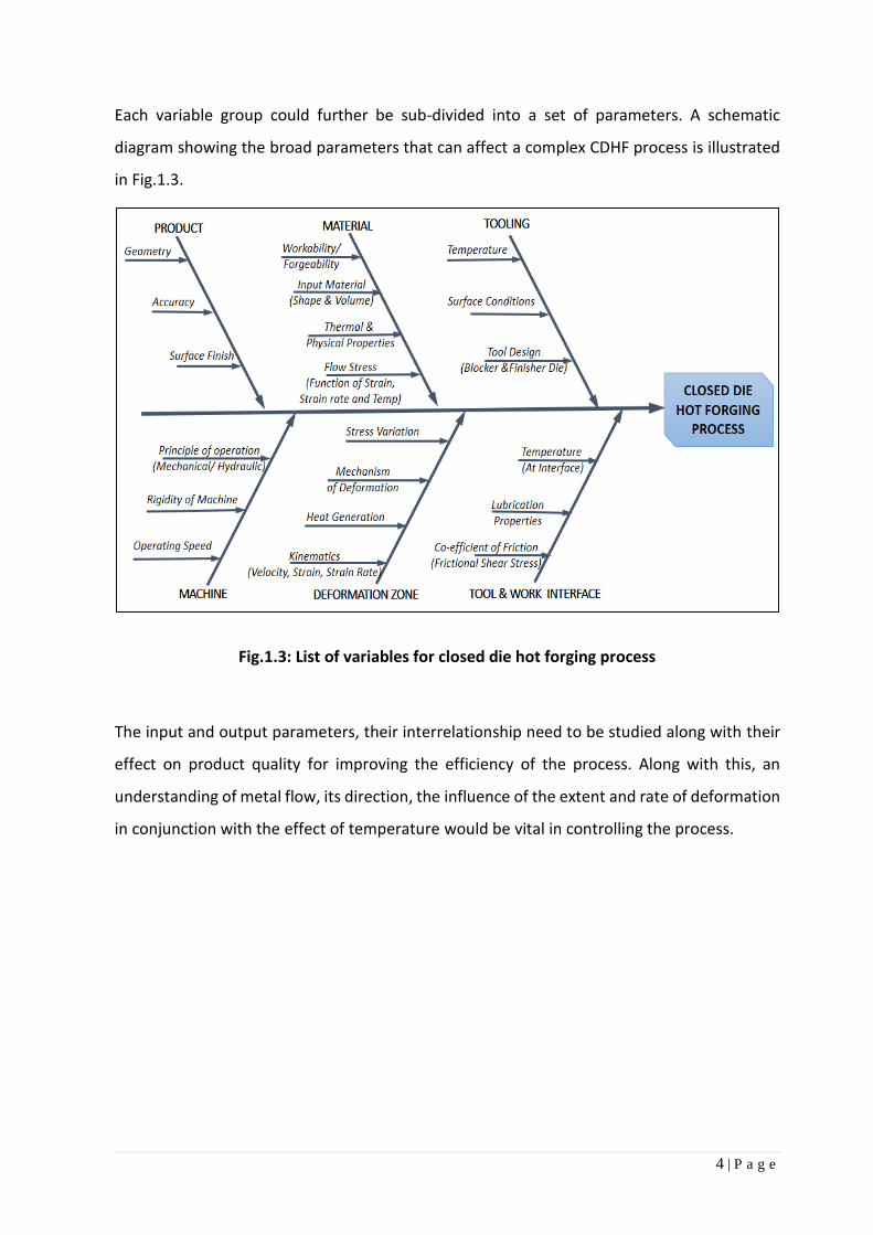
Each variable group could further be sub-divided into a set of parameters. A schematic
diagram showing the broad parameters that can affect a complex CDHF process is illustrated
in Fig.1.3.
Fig.1.3: List of variables for closed die hot forging process
The input and output parameters, their interrelationship need to be studied along with their
effect on product quality for improving the efficiency of the process. Along with this, an
understanding of metal flow, its direction, the influence of the extent and rate of deformation
in conjunction with the effect of temperature would be vital in controlling the process.

5 | P a g e
1.4: Major Factors influencing the Metal Flow
There are several factors that can directly influence the metal flow behaviour. They are as
follows:
1.4.1: Forging Temperature
In general, increasing the hot forging temperature (which is far above the recrystallization
temperature of the material) reduces the flow stress, the strain hardening coefficient and
hence the resistance of the material to deform. It is expected that, the forging load
requirement would go down.
It should also be noted that, additional heat is generated during the process due to the plastic
deformation and friction. Indeed, an appreciable fraction of the mechanical energy involved
during the process is converted to heat. This can contribute to an increase in temperature if
the strain rate is reasonably high.
1.4.2: Flow Stress
The flow stress refers to the instantaneous value of stress, under the given condition of
temperature which is required for continuous deformation or flow of material. This is the most
vital material variable in the metal forming analysis. For a given material, the flow stress ( 𝜎)
is a function of degree of deformation or strain (𝜖), rate of deformation or strain rate (𝜖̅̇) and
temperature of deformation (𝑇). [5]
𝜎 = 𝑓(휀, 𝜖 ̅̇, 𝑇) …… (Eq.1.1)
As has been mentioned, at the temperature of forging the strain hardening is low; hence the
rate of deformation or strain rate has a far greater effect on flow stress. The increase in strain
rate, increase the values of flow stress, in most cases.
1.4.3: Friction and Lubrication
The forging load applied to the die is transmitted to the workpiece through the die interface.
So, frictional conditions at the interface is vital to the metal flow. It can influence the metal
flow, die stress and increase the requirement of forging load. Appropriate lubricants are used
during metal forming operation to reduce friction, forging load and die wear, so as to improve
the metal flow in the lateral direction.

6 | P a g e
The interface shear friction law is used in metal forming analysis. Mathematically, [1]
𝜏 = 𝑓. �̅� =𝑚
√3�̅� …… (Eq.1.2)
Where,
𝜏 = Frictional shear stress
𝑓 = Friction factor
𝑚 = Shear factor
𝜎 = Flow stress of the material
The value of shear factor, 𝑚 lies between 0 to 1. The recommended value for steel forging
with graphite based lubricant is 0.3. [1, 28]
1.4.4: Forgeability of the Material
The forgeability of a metal refers to the ability to undergo deformation without causing
defects such as discontinuities or crack. The common tests for forgeability include upsetting
and hot-twist. The test is recommended to be performed at similar operating condition as
experienced in forging, such as temperature, strain rate. The forgeability also depends on
material characteristics such as tendency for grain growth, oxidation and so on.
1.4.5: Shape factor of Component and Die
The metal flow in the die cavity is greatly influenced by the geometry of component and die.
The simple shaped parts are easier to forge, compared to the complex shapes. The
components having higher surface area per unit volume can be termed as a complex shape
for forging. These parts with increased surface area are more critically affected by friction and
temperature variation. As a result, forging load tends to increase for complete filling of the die
cavity.
1.4.6: Die Temperature
Preheated dies are generally used in the hot forging process to avoid chilling effect at die and
workpiece interface which hinders the metal flow at surfaces. The heated dies also facilitate
die filling and reduce forging pressures. Typically, the die is heated in the range of 250-400 oC,
based on complexity of workpiece.

7 | P a g e
1.5: Typical Forged Components in Automotive: A Note
A typical flange yoke, used in the propeller shaft of heavy commercial vehicles may be
considered as a sample component. The propeller shaft is an important unit in the drive-line
system of the vehicle. The primary role of this unit, is to effectively transmit engine power to
rear axle. In cases of multiple rear axles, it is termed as inter-axle and transfers the power to
the next axle. A schematic representation of these units in vehicle assembly is shown in Fig.1.4.
Fig.1.4: a) Schematic layout of the propeller shaft assembly in the vehicle
b) Image of a typical propeller shaft assembly
The propeller shaft and inter-axle shaft may contain several flange yokes at the universal joint.
A typical arrangement of the assembly and its components are shown in Fig.1.5.
Fig.1.5: Typical arrangement of components in propeller shaft assembly
a b
8 | P a g e
As the unit primarily transmits torque, all the components are continuously subjected to cycles
of torsional fatigue. In actual service due to forward and reverse motion of the vehicle; the
power transmission cycle works in both directions. Thus, practically the component is
subjected to a reversible torsional fatigue cycle.
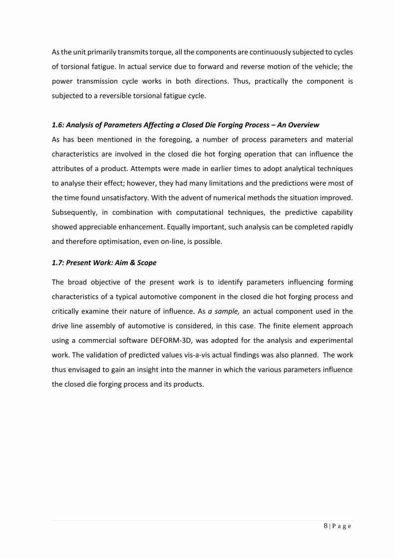
1.6: Analysis of Parameters Affecting a Closed Die Forging Process – An Overview
As has been mentioned in the foregoing, a number of process parameters and material
characteristics are involved in the closed die hot forging operation that can influence the
attributes of a product. Attempts were made in earlier times to adopt analytical techniques
to analyse their effect; however, they had many limitations and the predictions were most of
the time found unsatisfactory. With the advent of numerical methods the situation improved.
Subsequently, in combination with computational techniques, the predictive capability
showed appreciable enhancement. Equally important, such analysis can be completed rapidly
and therefore optimisation, even on-line, is possible.
1.7: Present Work: Aim & Scope
The broad objective of the present work is to identify parameters influencing forming
characteristics of a typical automotive component in the closed die hot forging process and
critically examine their nature of influence. As a sample, an actual component used in the
drive line assembly of automotive is considered, in this case. The finite element approach
using a commercial software DEFORM-3D, was adopted for the analysis and experimental
work. The validation of predicted values vis-a-vis actual findings was also planned. The work
thus envisaged to gain an insight into the manner in which the various parameters influence
the closed die forging process and its products.

9 | P a g e
1.8: Outline of the Report In the foregoing pages, an overview of the background against which the present work was
undertaken was given; one also got a glimpse of the broad aim of the study. Details about the
relevant literature, modalities of experimentation, analysis of results, discussion etc. are dealt
with, in a number of sections that follow. These are described below:
Chapter 2: Literature Survey
The current status of the field of closed die forging in general and methods of analysis
of the process has been examined here.
Chapter 3: Analysis of Closed die Hot Forging Process: Use of Relevant Techniques
Here, critical aspects of finite element (FE) method and its suitability for complex metal
forming analysis, such as that encountered in closed die hot forging process have been
dealt with. The approaches of design by simulation for process analysis is also discussed.
Chapter 4: Design considerations for the process
Contains the method adopted for generating the pre-requisite steps required for the
experimentation such as forging and die design specific to the component.
Chapter 5: Experimental work
Contains the details of experimental work done, including method of experimentation
and validation for the same.
Chapter 6: Analysis of experimental data
Contains analysis performed on the experimental data and the findings there upon. It
also contains discussion on the general observations.
Chapter 7: Conclusion and scope for future work
Includes the summary and concluding remarks. The scope for future work in this field
is also included.
10 | P a g e
CHAPTER 2
LITERATURE SURVEY
The broad objective of this chapter is to provide requisite background information relating to
the proposed study from literature. The identified areas of the survey include:
- Closed die hot forging (CDHF) process and the process parameters
- Approaches for Analysis of the closed die forging process
- Finite Element (FE) Analysis for CDHF process.
2.1: Closed Die Forging Process and Process Parameters
The closed die hot forging process is most suitable for generating complex shaped work parts
with reasonable profile accuracy. The process is quite complex from the analysis point of view
as there exist several parameters, that can influence the process. These parameters in broader
terms can be classified into two categories: design and process parameters.
The design parameters include the preform shape design and die design. The preform shape
design is primarily dependent upon the number of stages involved. The die design includes
parameters such as flash thickness, flash width, draft angle, corner and fillet radius, input billet
geometry etc.
The process parameters include input temperature of billet and die, interface friction, speed
of deformation etc. These have been studied in a number of publications; some of the major
ones would be dealt with.
The hot forging process under closed die condition were studied in terms of flash formation
by Tomov et al. [13]. A number of expressions proposed by earlier researchers for flash land
calculation were compared using both analytical and numerical approaches. The best
expression among the comparative work was identified so that it can be used as a first step
for die design.
A novel approach for preform shape design, which is considered as an important design aspect
in forging process planning was proposed by Sedighi and Tokmechi [14]. Here one starts with
a primary preform selection and improves the geometry at a second stage. The shape

11 | P a g e
improvement phase is driven by simulation, using a finite volume method in association with
parametric CAD tool. By defining the design variables as parameters, different sections of the
part are mapped to an algorithm. At a next step, the defined criterion refines the dimensional
values and the proposed model is generated.
Saniee and Hosseini [15] in their study showed that, input billet size and the flash dimension
exercise a significant effect on both forging load and metal flow in the die. In a comparative
experiment between two parts, it was observed that the die filling characteristic is more
sensitive to size of billet, in case of component shapes having a horizontal axis of symmetry.
The importance of corner radius and friction in the closed die forging process were highlighted
by Ab-Kadir [16] based on an exhaustive FE study. By conducting an iterative study on a bolt
head forging, the effect of corner radius on die filling was compared. It was found that
increased die radius in forging is favourable. Similar comparative study on friction showed
that, the forging load and consequently die wear increases with increase in frictional value.
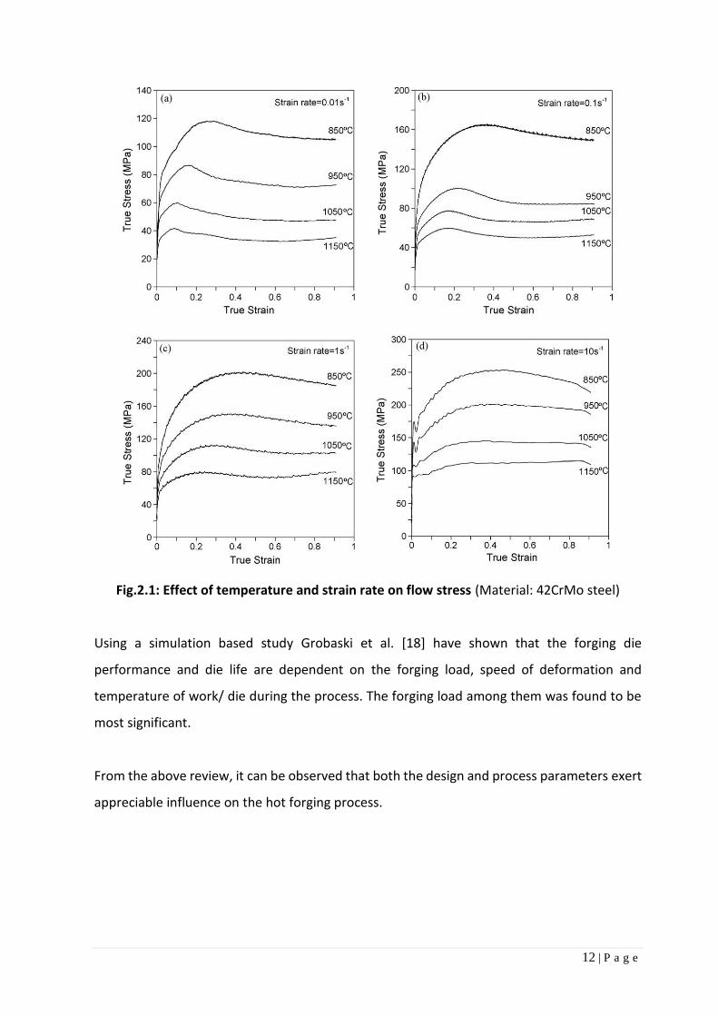
Using a thermo-mechanical simulator (i.e. Gleeble), the stress-strain behaviour of steel was
determined under compressive load at varying temperature and strain rate by Lin et al. [17].
The temperature range is kept as 850-1150 oC and strain rates varied between 0.01-50 s−1. It
was observed that the flow stress reduced with increase in temperature and it increased with
increased strain rate. The observed behaviour is shown in Fig.2.1 for a 42CrMo steel.
12 | P a g e
Fig.2.1: Effect of temperature and strain rate on flow stress (Material: 42CrMo steel)
Using a simulation based study Grobaski et al. [18] have shown that the forging die
performance and die life are dependent on the forging load, speed of deformation and
temperature of work/ die during the process. The forging load among them was found to be
most significant.
From the above review, it can be observed that both the design and process parameters exert
appreciable influence on the hot forging process.
13 | P a g e
2.2: Approaches for Analysis of the Closed Die Forging Process
Several methods, developed over time, exist for analysing the metal forming processes. The
historical development, is summarised in the work by Osakada [19]. The methods can be
broadly divided into Analytical Methods and Numerical methods.
The main objective of such analysis [1] is to:
Establish a kinematic relationship between the undeformed part and formed part, so
that the metal flow during the process can be predicted.
Predict the process output parameters such as load, stress, strain, temperature etc.
2.2.1: Analytical Methods
The analytical methods known are mostly based on certain assumptions, which help simplify
the formulation and an approximate solution is derived. Some of the common analytical
methods and their approaches are as follows:
(a) Uniform Deformation Energy Method
This method is based on energy balance or ideal work concept. In this method, a
homogeneous deformation is assumed without considering the effect of friction. An
average value for the forming load and stresses can be estimated by using this method.
(b) Slab Method
In this method, the work-piece is assumed to be comprised of several small sections
termed as slabs. Simplified assumptions are attributed for stress distribution in such
slabs. The method of solving involves formulation of equilibrium equations and solving
the same between the stress compatibility and boundary condition. The variation of
temperature and flow stress are not included in the formulation. So, this method gives
an approximate value for stress distribution and forming load prediction.
(c) Slip line Field Method
This method is mostly suitable for plane strain situations. Work material is assumed as
rigid and ideal plastic in nature. The velocity fields are calculated using plasticity
equations from the stress distribution. The effect of phenomenon such as strain

14 | P a g e
hardening is not included in the formulation. The variation is flow stress and its effects
are also not considered. So, this method is not suitable for finding out the exact nature
of distribution of stress throughout the work piece; as it occurs in the real life.
(d) Visio-plasticity Method
This method combines the experimental findings to the calculation. The work piece is
practically deformed and velocity vectors are found out by comparing the flow pattern
at different stages of deformation. The actual flow pattern is generated by imprinting
grids on the surface of the workpiece. The load and strain rates are calculated based on
velocity vector and the stress distribution is obtained by using appropriate plasticity
equation.
(e) Upper Bound Method
In this method, a suitable kinematically admissible velocity field is assumed, so that it
satisfies the velocity boundary condition. The calculation is based on limit theorem
concept and can predict approximate load and velocity distribution.
A review of the above mentioned analytical methods revels that, some of the idealised
assumptions in calculation, limit their capabilities for handling complex metal forming cases
such as closed die hot forging process. Moreover, none of the methods consider the effect of
temperature gradient in work material and its effects during the processing, which is
predominant with CDHF process.

15 | P a g e
2.2.2: Numerical Methods
Among the known numerical methods, the following methods have been mostly used:
(a) Finite Difference Method (FDM)
In finite difference method, the governing partial differential equations are formulated
as difference equations. The temperature gradient can be modelled using this method.
But the applicability of this method is limited to cases with simple boundary conditions
only.
(b) Finite Element Method (FEM) [6]
In this method, the workpiece is split into a finite number of discretised elements over
which the behaviour is described by differential equations. The elements are connected
at common points termed as nodes. The discretization technique enable this method to
handle complex geometrical shaped components in the analysis. The complex real life
interaction effects can be coupled to the main analysis. So FE modelling technique can
be concluded as the best method for analysis of complex forming situations such as
CDHF process.
2.3: Finite Element Analysis for CDHF Process Among the numerical methods, the finite element modelling technique is found to be adopted
by many researchers for analysis of closed die forging process, in order that complex shapes
could be handled. The development of hardware to support the high speed computing along
with availability of reliable commercial software codes can be considered as a prime reasons
for the adoptability of FE Method. The method of calculation is automated, in the available
commercial simulation codes (e.g. DEFORM). The FE modelling software is normally used in
conjunction with a CAD (Computer Aided Design) software, for accurate modelling of
component and die. These models are imported into the FEM software for further processing
such as discretization, application of boundary condition and computational analysis work.
The solver used for analysis of CDHF process should be able to model both deformation and
thermal analysis, as the actual processing is done at elevated temperature.
16 | P a g e
Oh et al. [20] dealt with different formulations used in FE codes for analysis of metal forming.
The capabilities and application are discussed in details showing its suitability for process
simulation and optimisation. The method of coupled formulation for heat transfer, including
heat generation due to plastic deformation are also explained along with guiding equations.
The major features of a commercially available software (DEFORM) and its approach to
perform complex analysis is demonstrated. The significance of FE solution in steps for large
deformation analysis and the role of an automatic mesh generator is highlighted. The post
processing and use of predicted output in different real life application is presented as case
studies.
The superiority of FE method compared to analytical methods such as slip line method in
dealing with die forging analysis was shown by Tomov et al. [21]. This work also covers some
of the critical design considerations, including pre-form and flash design analysis. The
validation of results generated from numerical method using simulation is encouraging.
Santos et al. [22] emphasised on simulation techniques for complex metal forming analysis
and tool design in case of forging and sheet metal forming. Real life components are
considered as a sample case for the study, to explain the advantages of simulation driven
approach over traditional practices. Park et al. [23] worked out a detailed process analysis
methodology for multistage forgings of complex shaped components. As a sample, the CV
joint housing used in automotive transmission line was taken up, where both geometry and
tolerance in manufacturing are crucial. Suitability and accuracy of the FE method for such
complex component manufacturing is validated with actual trial. Gangopadhyay et al. [24]
used three dimensional finite element analysis method to simulate the multistage forging
process, adopted in manufacturing of railway wheel. A coupled thermo-mechanical analysis
along with basic FE formulations for metal forming was used. The analysis was performed
using DEFORM-3D software and the scope was extended to the final product production,
including trimming operation. It was also observed that this method can be deployed for
analysis of forging defects such as lap formation and under-filling of the die cavity, so as to
improve product quality and productivity. The relevant mathematical formulations are also
discussed. Satish et al. [25] used the simulation based approach to multi-stage hot forging
process analysis of automotive front axle manufacturing. The approach was to optimise the
preform design at the pad section of the axle using DEFORM software.

17 | P a g e
The simulation based approach in comparison to conventional approach was found more
suitable for complex geometries.
2.5: Summary Observations and Directions for the Present Work
The detailed investigations of works done by different research groups in the area of metal
forming reveal that both design and process parameters contribute to the forging process. It
is also concluded that a generic solution cannot be worked out, for all shapes of components.
Finite element method is found to be the best suited approach for analysis of complex shaped
real life components.
In order to gain a deeper understanding of the closed die hot forging process for specific cases,
it was considered appropriate to take up a typical automotive component. Thus, a flange yoke
used in driveline for transmitting power was chosen for studying the influence of various
parameters in its manufacture through closed die forging, based on FEM.
The details of the FEM approach used in this study, selection of variables, experiments
conducted, results and analysis etc. are given in the next chapters.

18 | P a g e
CHAPTER 3
ANALYSIS OF CLOSED-DIE HOT FORGING PROCESS: USE OF RELEVANT TECHNIQUES
As has been mentioned earlier, the numerical techniques are superior to other methods in
analysing the influence of various parameters involved in a closed die hot forging process. The
present approach has therefore been to make use of Finite Element method (FEM); which can
handle more complex geometry of the work-piece. Further, complex interaction of factors can
be coupled to the main analysis in FEM. Descriptions of the methodology to adopt FEM to
closed hot forging would be made. Simulating the forging process would be an effective way
of looking at various parameters and their influence in a virtual manner even without
experiments; the process would be described in this section. There are commercial packages
available today based on the FE-method, they would be looked into. One such, i.e. DEFORM,
has been chosen for the current study; some details of the same would be provided.
3.1: FEM for Analysis of Closed Die Hot Forging Process: A Summary The general advantages of FEM for dealing with deformation of metals have been noted in
the earlier chapter. Specific aspects of the FEM in handling the complex analysis of closed die
hot forging may be summed up as follows:
i. Practically all shapes, including complex three dimensional, unsymmetrical geometries
along with die geometry can be considered for analysis.
ii. Localized phenomenon causing variations in parameter such as stress can be included
in the analysis.
iii. Variation in the flow stress occurring at different region, due to variation in
temperature can be included in the analysis.
iv. The phenomena of adiabatic heat (heat generated due to work done in forming) can
be coupled to the analysis.
v. Some of the redundant work done during the overall forming process can also
accounted in the process. Such phenomenon is quite common in the mechanism of
flash generation, bend formation etc.
19 | P a g e
vi. The effect of varying strain rate can be included in the analysis.
vii. Effect of tool and workpiece temperature and localized chilling at the interface can be
included in the analysis.
viii. Environmental effect such as heat transfer with the surroundings and its effect on
forming can be considered.
ix. Interpolation of result in different forms such as directional stress, strain, strain rate
can be interpolated and the stored data can be reused for advanced analysis such as
fatigue and die failure.
x. With the availability of reliable commercial codes, analysis is continuously getting
refined to generate more accurate and faster results.
3.2: Description of FE Process for Closed Die Forging
The basic approach here is to split the basic problem into small units (discretisation), so that
suitable formulations for each can be made. The final solution is achieved by assembling the
units and solving it.
The finite number of small units, which in combination represents the whole problem is
termed as elements and the connecting points are known as nodes. The behaviour of the
material along with operating boundary conditions are carefully embedded to the formulation
by using different relational constraints to the elements and nodes. Basic finite element
formulations and solving method are well documented in various textbooks. [9, 10]
The modified process for deformation analysis can be described as follows:
- The total solution is achieved in a set defined steps, so that the actual nature of
deformation can be captured.
- At each step a smaller increment of the die travel is considered, and the relevant
calculation is performed. This is repeated until the specified distance or stopping
criteria is not achieved. The general stopping criterion is die distance, limiting value for
load or minimum values for velocity or strain etc.
- In case of complex shapes, there is a drastic change while moving from the initial shape
to the final geometry. This is addressed by frequent re-initiation of meshing cycle, as
and when the element shape integrity is lost beyond the defined value. This is known
as re-meshing cycle, which can be manual or automatic.

20 | P a g e
The global stiffness equation for the workpiece is generated by assembling the
individual elemental equation. The governing equation defining the relation is [24]:
𝐾∆𝑣 = 𝑓 …… (Eq.3.1)
Where,
𝐾 represents the global stiffness matrix
∆𝑣 = incremental velocity
𝑓 = global force vector
The discretised model generated during the project work is shown in Fig. 3.1.
Fig. 3.1: Discretised model of die and billet assembly
(Initial contact between die and billet shown)

21 | P a g e
3.3: FE Formulation for Metal flow in Hot Forging:
In case of closed die hot forging, the primary interest is to track the material flow, through the
die cavity. For deciding metal flow and its direction, minimum work rate principle is followed.
Consequently, the velocity distribution which predicts lowest work rate is chosen for deciding
the flow direction. This principle is based on the practical phenomenon that the material will
always flow in the path of least resistance.
The method of formulating and solving metal forming problem is performed by using the
variational approach where the proper function is dependent on specific constitutive
relations. The velocities are solved, keeping the variation of the function as stationary. [6, 20,
24, 28]
The functional (function of function) considering rigid-viscoplastic FE formulation is as follows:
𝜋 = ∭ 𝐸 (𝜖�̇�𝑗)𝑑𝑉 − ∬ 𝐹𝑖𝑢𝑖𝑑𝑆 …… (Eq.3.2)
Where,
𝐸(𝜖�̇�𝑗) is work function
𝐹𝑖 is the surface traction.
The constraint for material incompressibility on the admissible velocity fields is removed using
the large positive penalty constant K:
𝜎𝜋 = ∭ 𝜎 𝛿휀̅̇ 𝑑𝑉 + 𝐾 ∭ 𝜖�̇� 𝛿 𝜖�̇�𝑑𝑉 − ∬ 𝐹𝑖 𝛿𝑢𝑖𝑑𝑆 = 0 …… (Eq.3.3)
Where,
𝜖�̇� is volumetric strain rate
The first integral defines the plastic work due to deformation
The second term maintains volume constancy by multiplying the change in volume with a
large penalty constant
The third integral defines the work due to surface traction

22 | P a g e
The metal flow criterion is governed by J2 flow theory; as the yielding of the material is
assumed to begin, when the second deviatoric stress invariant reaches the critical value. The
formulation neglects the effect of first set of stress variant as hydrostatic component of the
stress tensor do not contribute to the deformation of metal. This is also alternatively known
as von Mises yield criterion.
For Von Mises yield criterion,
Effective stress, 𝜎 =1
√2. √(δ1 - δ2)2 + (δ2 - δ3)2 + (δ3-δ1)2 …… (Eq.3.4)
Effective Strain, 𝜖̅ =√2
3. √(ε1 -ε2)2 + (ε2 -ε3)2 + (ε3-ε1)2 …… (Eq.3.5)
In case of hot forging, heat energy and thermal effects are embedded to the formulation as
coupled analysis as their effects are significant. The major portion of the heat is generated due
to the plastic work and the friction at the interface. Some amount of the heat is lost at a
varying rate due to the contact with the die at lower temperature in physical phenomenon
such as convection and radiation by the exposed surfaces.
The adiabatic heat generation rate in the workpiece can be determined by
�̇� = 𝜅𝜎𝑖𝑗𝜖�̇�𝑗 …… (Eq.3.6)
Where,
𝜅 = fraction of mechanical work converted to heat (0.9 to 0.95 is considered for forging)
𝜎𝑖𝑗 is component of stress tensor
𝜖�̇�𝑗 is component of strain rate tensor
The inclusion of the thermal consideration such as heat transfer and heat generation as
coupled analysis to the main formulation makes the mode as non-isothermal in approach.

23 | P a g e
3.4: Design by Simulation
Simulation is the process of conducting virtual computer based experiments, founded on
mathematical and logical modelling techniques. The finite element based modelling is the
most adopted simulation technique for engineering analysis. Design by simulation is a
systematic approach where the objective is to perform virtual iterative trials to understand
the effect of parameters on the output and the overall behaviour of the system as a whole. In
case of a bulk forming process such as forging, the simulation technique can be used both for
process analysis and die design.
3.4.1: Purposes of Design by Simulation:
The purpose of process modelling through simulation aims at the followings:
- To gain a comprehensive insight into the process to understand different mechanism
and phenomena involved.
- The study can be performed in isolation, so that actual setup is not disturbed.
- Reduces effort on expensive trials, thus reduce overall development time.
- Testing the effectiveness of new concepts before actual implementation.
- Reduced effort on analytic requirements.
- To find out the results in easily demonstrable models, which can be further scaled to
advanced analysis, such as die wear, die life estimation etc.
3.4.2: Precautions in Design by Simulation:
There is a set of cautions which should be borne in the mind during performing simulation
driven process analysis. They are as follows:
i. Simulation is majorly based on finite element analysis, which is an approximate method by
itself.
ii. The method of formulation decides the accuracy of the output, such as element size.
iii. The exactness of the input parameter to the formulation decides the accuracy of the output
result. So, process input parameters should be correct and reliable.
iv. It is always recommended to verify the initial study with actual trial to find out the
correlation.
v. For new development the results can be benchmarked with a similar known case.

24 | P a g e
vi. Simulation by itself cannot solve engineering problems. Based on the output results,
suitable inference for problem solving can be initiated. However a confirmatory test on the
decided solution can be verified before actual implementation.
3.5: Commercial FE-Packages Suitable for Closed Die Forging: Introduction to DEFORM
Rapid development in high speed computing and processing hardware, has enabled FEM
codes be used in many engineering analysis. There are a number of reliable general purpose
FE modelling packages available such as ANSYS, NASTRAN, DYTRAN, MARC, LSDYNA that can
predict stresses in both tool and work piece.
Customised FEA packages are also available which are tailored, specifically to address the
requirements of metal forming analysis. A list of such specialised FE modelling software,
capable of simulating closed die hot forging process is shown in Table 2.1.
Table 2.1: List of commercial FE software, suitable for analysis of CDHF process
DEFORM (Design Environment for Forming) is one of such customised FEM- codes, tailored to
address analysis requirements of the entire deformation and allied processes. In this project
DEFORM-3D module is extensively used for the FE modelling and analysis work.
Sl Commercial Name of Software Company/ Team Developed the Code
1
DEFORM (Design Environment for Forming)
Scientific Forming Technologies Corporation (SFTC)
2 FORGE Transvalor S.A.
3 SIMUFACT Simufact Engineering GmbH
4 QForm (Quantor Form)
Quantor Form Ltd

25 | P a g e
3.5.1: Features of DEFORM Suitable for Closed Die Hot Forging Process
Some of the main characteristics of DEFORM that make the package appropriate for CDHF
are:
- Coupled modelling of deformation and heat transfer can be performed
- Extensive material property database at high temperature are pre-built with the
system along with provision to include user defined input.
- Rigid, elastic and plastic models are included, which can be directly applied to the die
and work-piece based on type of analysis.
- Integrated equipment models of various types are pre-built into the system, which can
be easily reconfigured. (Such as Hydraulic press, Mechanical cranked press etc.)
- Point tracking system to track the exact flow is available.
- The flow net technique can assist to predict grain flow behaviour.
- Contact element pattern can ensure die filing characteristic.
- Information on metal flow, resulting flow velocity, strain rate, strain, stress, load,
temperature and die stress can be found out.
- Contoured plot of the output parameter in post processing along with animation can
help to understand, complex behaviour during actual processing.
3.5.2: Simulation Steps for CDHF process in DEFORMTM:
DEFORM-3D module possesses specifically designed templates for process simulation of bulk
forming analysis. This can handle complex 3-dimensional geometries of both work piece and
die by incorporating solid elements. The Automatic Mesh Generator (AMG) produces
optimized mesh based on user input. The auto remeshing feature keeps on modifying the
mesh when the acceptable criteria are violated due to deformation. The rules for such criteria
can be defined by the used, prior to starting the simulation study. Most of the settings can be
manually overridden, in case need arises. The three functional segments in the module are
[28]:
(a) Pre-Processor
(b) Simulation Engine/Solver
(c) Post Processor

26 | P a g e
(a) Pre-Processor:
The pre-processor assists and compile the input data for the simulation. In some of the
cases, it helps the user to visualise and analyse the input data using the graphical user
interface. The type of input includes:
Object Description: The data associated with geometry, object type, mesh definition,
temperature, die movement, boundary condition etc.
Material Data: Material property data for both work piece and die. The data should be
sufficiently describing the behaviour of the material, which it will reasonably experience
during the entire deformation cycle.
Inter-object Conditions: Data describing the interaction between the workpiece and die
including contact, friction and heat transfer criteria.
Simulation Controls: Data related to control the numerical behaviour of the solution
including solving algorithm type, formulation type, remeshing criteria, stopping criteria,
sub stepping method, data storing steps etc.
(b) Simulation Engine/ Solver:
The actual FEM based calculation is performed by the simulation engine or solver. Based
on the input data, necessary formulations are initiated by the solver and the required
calculations are performed sequentially. The total deformation is calculated in a series
of steps and the results are stored for such steps. Several remeshing cycle may be
initiated during the solving cycle based on the defined criteria. The stored simulation
results can accessed by the user through the post -processor. The type of formulation
available for forging include heat transfer, isothermal and non-isothermal simulation.
(c) Post Processor:
The Post Processor is generally deployed to visualise and analysis the result. The stored
result by the solver can be plotted graphically or in alphanumeric form by the post-
processor. The graphic interface is extensively used for such interpolation of result. The
graphic representation includes mesh, contour plots of distribution of strain, stress,

27 | P a g e
strain rate, temperature and velocity vectors in various forms. The load / stroke curves
can also be interpolated from the stored data. The other useful capabilities in the post
processor include generation of point-tracking and flow net. This helps in visualisation
of metal flow pattern and predict grain flow orientation.
28 | P a g e
CHAPTER 4
DESIGN CONSIDERATIONS FOR THE PROCESS
The broad objective of this chapter is to deal with some of the design guidelines, appropriate
to the intended component, including die design, so that the prerequisite steps can be
performed for the analysis of the process. The manufacturing route for the component is
finalised as closed die hot forging based on the complexity of the geometry, tolerance
requirement for the component, the extent of deformation required to form the shape, and
mass production requirement of the component.
The involved design phase can be broadly divided into two stages: Product Design Stage and
Die Design Stage
4.1: Product Design Stage:
The engineering design team finalise the geometry, dimension, tolerance and material
requirement for the final component. This is based on intended application in service,
including the desired performance characteristic for the particular part. The typical output is
a machine drawing of the final required part; which include post forging operations such as
machining, tolerance and surface finish requirements. The machine drawing of the considered
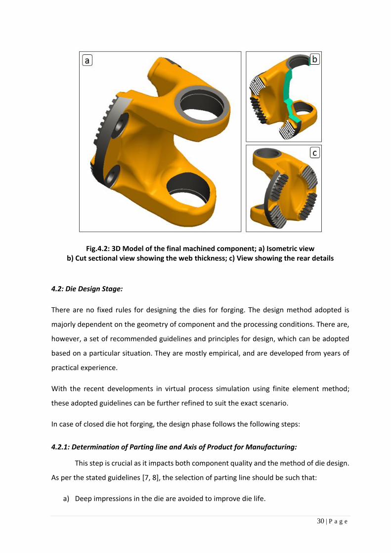
component is shown in Fig.4.1. A 3D model displaying different views is shown in Fig.4.2.
The first step for a production engineer to convert the machine drawing into forging part
drawing. Understanding of the function of actual part in service can be considered as a
prerequisite to efficiently handle this conversion phase. This understanding also improves the
decision making ability for the subsequent design stages. The selected component is a part of
the universal joint used in propeller shaft for heavy commercial vehicle application. The
component is known as “Flanged Yoke” in automotive terminology. It is mostly subjected to
torsional loadings; as the whole propeller shaft is designed to efficiently transmit the engine
torque to the rear axle.

29 | P a g e
Fig. 4.1: Machine drawing of the component considered in the project- Flange Yoke
Ø0.03E Ø0.03D
T S
ER
RA
TIO
N A
S P
ER
IS
O 1
2667
30 | P a g e
Fig.4.2: 3D Model of the final machined component; a) Isometric view b) Cut sectional view showing the web thickness; c) View showing the rear details
4.2: Die Design Stage:
There are no fixed rules for designing the dies for forging. The design method adopted is
majorly dependent on the geometry of component and the processing conditions. There are,
however, a set of recommended guidelines and principles for design, which can be adopted
based on a particular situation. They are mostly empirical, and are developed from years of
practical experience.
With the recent developments in virtual process simulation using finite element method;
these adopted guidelines can be further refined to suit the exact scenario.
In case of closed die hot forging, the design phase follows the following steps:
4.2.1: Determination of Parting line and Axis of Product for Manufacturing:
This step is crucial as it impacts both component quality and the method of die design.
As per the stated guidelines [7, 8], the selection of parting line should be such that:
a) Deep impressions in the die are avoided to improve die life.

31 | P a g e
b) Die side thrust is minimised, to avoid die shift during the forging cycle.
c) Largest periphery is preferred to be placed around the parting line; so that it is easier
to force metal laterally to spread into the cavity. Putting the largest flat surface on the
parting line is the other variation of this criterion.
d) Desired grain orientation is achieved for the part to be manufactured.
Reviewing the application of the component reveals that, the component is continuously
subjected to torsional fatigue cycle. The torque is transmitted to the body, as a coupling force
acting through the holes present in the yoke. The net effect can be summed up as constant
bending forces acting on the sections of the yoke.
In order to improve the mechanical properties of the component, it is desirable that the grain
flow orientation is perpendicular to the loading direction. This will improve the fatigue
resistance of the component.
Thus, reviewing the actual application of the component, one could select the parting line.
4.2.2: Designing the Forging Part The first step here is to initiate necessary design changes in the forging part design so that the
component can be formed with the decided parting line. Consequently some of the geometry
needs to be simplified or modified. In case of the considered component, the holes in the yoke
lie in the perpendicular axis of forming; so the yoke is to be formed as solid in forging and the
hole will have to be generated afterwards by machining.
The next step is to add up the required allowances to the forging part design. The considered
tolerances are:
i. Machining allowances
ii. Straightness or uneven allowances
iii. Contraction allowances
The standard charts and formulae, recommended in IS 3469-1974 (Indian Standard) is referred
to finalise the allowances to the forging part design.

32 | P a g e
The images of forging part model is shown in Fig.4.3.
Fig. 4.3: 3D Model of the generated forged component; a) Isometric view b) View showing the rear details; c) Cut sectional view showing the web thickness
4.2.3: Incorporating the Draft Angle in Design
Draft refers to the taper generated in the internal and external sides of a closed die forging to
facilitate easy removal of components from the die cavity. In the actual practice, the draft is
generally modelled in the forging component design and the replica is generated in the die by
machining. The selection of draft angle should be optimal, as excess draft angle increases
allowances in component; thus increasing the final weight of component.
The draft angle is included in the vertical walls with respect to the axis of forming. Normally
draft provided on the inner surface is larger than the outer surface drafts, as upon cooling the
forging shrinks both radially and longitudinally.
Draft angle value also is greatly dependent on the type of equipment used and complexity of
forging. The draft angle value is decided as 3o for external 5o for internal surface based on
recommendation table, considering mechanical crank press and steel as forging material. [7]
33 | P a g e
4.2.4: Flash and Gutter Design
Flash refers to the excess metal normally attached at the periphery of the workpiece that is
subsequently trimmed in a separate die. It is formed in the flash land, normally adjacent to
the die impression cavity. The flash design is crucial, as it performs two contradictory, yet
important roles during the actual shaping of metal.
(a) Acts as a restriction to the outward flow of the metal during the first phase of
forming, so that remote corners and deeper cavities can be filled up.
(b) Pushes out the excess metal from the cavity in the second phase, after complete
filling of the cavity so that the excess pressure is relieved.
Apart from this it also acts as a cushion from impact blow generated at high strain rate
forming.
Most of the finisher forging dies are designed to accommodate flash. However, in industries,
flash provision is given to the blocker dies also, if:
- Less numbers of stages of forming is desired
- Complex shaped workpiece with large multi-directional deformation is to be achieved
The optimum value of flash thickness has been always desirable; as smaller value will
necessitate greater energy for bringing forging to size, while bigger value may cause
inadequate die filling.
Flash Gutter is the cavity designed to accept the excess metal extruded out through the flash
land. Mostly the gutter cavity is placed adjacent to the flash land.
4.3.5: Design Considerations for Fillet and Corner Radii
Design of fillet and corner radii affect grain flow, forging load, die wear, grain flow and the
amount of metal to be removed during machining. So, proper selection of the fillet and corner
radii is a vital aspect in the forging die design. As a rule, all possible sharp corners must be
avoided in forging design as they tend to weaken both the dies and finished forgings. It also
hinder the smooth flow of metal causing under-fill, excess load and die wear. In the present
design of the blocker die, the radius and fillets are maintained in the range of 5- 12 mm.
34 | P a g e
4.3.6: Deciding the Number of Stages for Forging:
Practical industrial forging is generally consists of multiple stages. The number of stages is
dictated by the complexity in geometry, nature of metal flow and the expected accuracy of
the component. Considering the geometry of flange yoke a three stage forming is felt both
adequate and economical. The planned stages are as follows:
a) Upsetting : Primarily to remove the oxide layer and prepare the initial billet for
subsequent processing.
b) Blocker stage : To give the primary shape to the component along with attaining
maximum critical metal flow.
c) Finisher stage : To achieve the final dimensional requirements of the component.
The next subsequent step is trimming, to remove the generated flash is not included in the
scope of this project.
Considering the component design, the preferred practical way to approach stages of die
design, is to design in the reverse order. This means the first finalise the design of finisher
stage and then blocker.
a) Finisher Die Design
As discussed, the finisher stage gives the final desired geometry and dimension to the
component. The steps followed for design, are as follows:
i. Die block shape is considered as round and the overall dimensions are considered to
suit existing die holding block.
ii. As per parting line the top and bottom die design is finalised.
iii. The die cavity is in both halves, by taking forged part design as reference.
iv. Shrinkage allowances is added to the die cavity considering steel as the work material.
v. Flash land and gutter design are included.
vi. The round circumferential die lock is introduced to encounter side thrust to the die.
vii. Pin ejection mechanism is added at suitable locations for assisting removal of the
component after forming.
A typical arrangement of the finisher die designed for this project is shown in Fig.4.4.

35 | P a g e
Fig.4.4: a) Sectional view of Finisher die set assembly with ejection holes a) Top die model, c) Bottom die model
b) Blocker Die Design
The major role of the blocker stage is to achieve desired metal distribution from the simple
shaped billet, so as to supplement complete die filling at finisher stage. This is the crucial stage,
where maximum metal flow is expected; so as to achieve production of component in less
number of stages. It is consciously decided to add flash at this stage also, as otherwise
controlling the metal flow in such complex shaped cavity will be difficult to be achieved in one
stage only.
The step followed for the design is as follows:
i. As like finisher, the die block shape is inherited to suit the existing die holding block.
ii. As there is no fixed rule, a conscious target of achieving around 70% of the forming at
the blocker is decided. The primary objective is set as to avoid major forming in finisher
stage, so that the sharp radius and stringent dimensional requirement of the final
component can be met.
iii. A shape for the blocker stage is worked out, considering it resembling to H-section.
iv. Overall forming height at yoke is reduced by 20% and fillet radius values are made
larger (2 to 3 times) aiming reduction in the forging load in blocker stage.
36 | P a g e
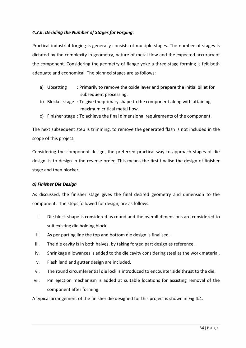
v. Based on the shape, the die cavity is in both halves are generated.
vi. Shrinkage allowances is added to the die cavity considering steel as the work material.
vii. Flash land and gutter design are included.
viii. Cavity for the initial location of billet in the die is incorporated in the design.
ix. The round circumferential die lock is introduced to encounter side thrust to the die.
x. Pin ejection mechanism is added for assisting removal of the component after forming.
A typical arrangement of the finisher die designed for this project is shown in Fig.4.5.
Fig. 4.5: a) Sectional view of Blocker die set assembly with ejection holes b) Top die model, c) Bottom die model
c) Upsetter Die Design:
As the main objective at this stage is to remove the scale or oxide layer resent in the surface
and prepare the billet material for subsequent operation; the upsetting die is decided to be
kept as flat for simplicity. This stage is not well documented in texts, but still is an essential
step for dealing hot rolled billet materials as input. The oxide layer is detrimental to the die
life and tends to produce defects in the component such as scale pit. Its presence at the die-
workpiece interface also adversely affect the metal flow. A vertical upsetting of 4 mm is
decided for the considered component.

37 | P a g e
CHAPTER 5
EXPERMENTAL WORK
This chapter includes the experimental work done on the chosen component, data generation
from simulation driven process design and validation with real forgings.
5.1: Determination of Stock/Billet Size for the Experiment
As the first step, the machine drawing of the component was studied and model for the same
was generated using the PTC Creo solid modelling software. It is then converted to into the
forging model by introducing simplification of features and adding up allowances; as discussed
in Chapter-4. The next step is to decide the input billet size for the processing. Referring to the
data generated from model, we can find the followings:
1. Net weight of the finished component
= volume of the finished component (from model) x density (steel)
Volume of forging = 465391 mm3
Density of material = 7.86×10⁻⁶ kg/mm3
Therefore, the net weight of the component is 3.66 kg
2. Net weight of the forging component
= volume of the forged component (from model) x density (steel)
Volume of forging = 613641 mm3
So the net weight of the component is 4.82 kg
3. Estimated flash loss
= (15 to 20) % of the net forging weight based on complexity of geometry
= 0.96 kg (considering the upper limit)
4. Required input billet weight
= Net weight of the forging + Flash loss
= 5.78 kg

38 | P a g e
5. Approximate yield of production
= (Net weight of the forging/ Billet input weight) x 100
= 83.4 %
In general, square, rectangular shaped billets are preferred over round; for forging such
complex shapes. The flat side of such billets ensures proper seating in the cavity, and less
attention on operating required.
Considering square billet with rounded corner of 65mm dimension: (Corner radius = 4mm)
Cross-sectional area = 4211.27 mm2
Length of billet required = (Required weight/density of material) /Cross sectional area
= 174 mm (Approx.)
So, the derived input billet dimensions are (SQ 65 x L 174) mm.
5.2: Determination Flash Land Dimensions
The primary role of flash land is to generate desired restriction to undesired metal flow. It is
characterised by the width to thickness ratio (w/t). The calculation for the flash land are mostly
empirical, developed by different researchers. As flash design is an important input to the
process, calculation is done using different method [7]. The result of the same is summarised
in Table.5.1.
Table 5.1: Summarised result of flash thickness calculation
(*) – Calculated values are rounded off to the closest suitable values
Reference Work (Author) Method of Calculation
(Flash thickness)
Calculated Value
(*)
1. Vieregge 𝑡 = 0.017𝐷 +1
√𝐷+5 ...(Eq.5.1) 2.8 mm
2. Neuberger & Mockel 𝑡 = 0.89√𝑊 − 0.017𝑊 + 1.13 ...(Eq.5.2) 3 mm
3. Teterin & Tarnovski 𝑡 = 2√𝑊 3
− 0.01W − 0.09 …(Eq.5.3) 3.2 mm

39 | P a g e
As per the design, D= Equivalent diameter = 160 mm
W= Forging weight = 4.82 kg
Considering different method and calculation, the average recommended flash thickness for
the considered component is found out as 3 mm
Similarly, for calculation of the flash width, the following empirical equation is used [1]
𝑤
𝑡=
30
√𝐷+[1+2𝐷2
ℎ(2𝑟+𝐷)]
3 …… (Eq. 5.4)
As per the design, D= Equivalent diameter = 160 mm
h= Height of rib = 100 mm
r= Radial distance from centre to rib = 60 mm
t= Flash thickness (Calculated) = 3 mm
The calculated flash width is found out to 16 mm (Approx.)
The calculated flash dimensions are used for the initial die design.
5.3: Actual Experimental Setup:
The actual trial was taken at the forging division of M/s RSB Transmission (I) Ltd., located at
Mania, Cuttack. The following facilities of the plant were used for the experimental work:
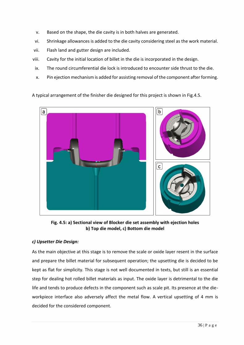
I. Mechanical cranked press of capacity 2500T was used for the forging operation. In
Image of the setup is shown in Fig.5.1. The inline induction heating arrangement was
used for heating the billet to required temperature.
II. CNC Vertical Milling machine was used for manufacturing of dies.
The other specification/ trial condition are as follows:
I. H13 grade material was used for manufacturing of the dies.
II. As per design specification, 37 C15 material was used as the billet material.
III. Colloidal graphite solution along with water, (In a ratio 1:20) was used during the
process as lubricant.
40 | P a g e
Fig.5.1: Machine used for experimental trial; a) Mechanical cranked press with automated
induction heating arrangement b) Front view of the press machine
5.4: Verification and Validation of Experimental Procedure:
The selected method for metal forming analysis is simulation driven. A simulation predicts the
desired behaviour, based on mathematical and computational models. In this particular
experimental model extensive finite element formulations are used.
Verification in general terms, refers to checking the correctness of the formulated model.
Whereas validation refers to checking the exactness of the model to predict the real life
situation. So, the validation of the initial set results is found essential to:
- Ensure that the input values and assumptions made are correct or justified.
- The model is adequate to predict actual behaviour.
- Correlation between the predicted value and the actual findings.
To validate the adequacy of the model, an actual trial was conducted on the machine.
The input parameters were measured during the process. These input values were fed to the
simulation model, along with some suitable assumptions.
The validation criteria were set as:
- Mapping the generated flash pattern and its dimensions at the last forging stage.
(i.e. finisher stage)
- Grain flow pattern mapping, to ensure that the metal flow direction is identical.

41 | P a g e
In the absence of direct load measurement device on mechanical cranked press used, it is
believed that the above two criteria should be acceptable to check the model adequacy.
In the actual trail the billet material is processed through all the three stages of forging.
(i.e. - upsetting, blocker and finisher stage). Similarly a three stage trial is performed using
DEFORM-3D software. The generated flash pattern in both the actual and the simulation result
was found identical. The metal flow pattern is also found similar. The comparison between
actual and predicted flash pattern is shown in Fig.5.2. The comparison of the metal flow
pattern at central cross section is shown in Fig.5.3.
Fig.5.2: Comparison between Actual Vs. Predicted Flash Pattern; Different Views ( a,c- Actual Component; c,d- Simulation Prediction )

42 | P a g e
Fig.5.3: Comparison of Metal flow Pattern; a) Cross section of Actual component
b) Predicted pattern by Simulation along with flash
The dimensional comparison of actual finding vs. predicted value of flash width is compared
in Table 5.2.
Table 5.2: Dimensional validation table for flash width/pattern (Actual/Predicted)
Sl Region of
Observation
Actual trial findings Prediction by
simulation Variation in %
w.r.t actual trail findings
Observed values (mm)
Mean Observed value (mm)
Mean
1 Region-A
(Flash generated at yoke area)
32.44 32.62 32.94 32.78 32.68
32.692
32.82 34.86 34.78 34.84 34.84
34.828 6.53%
2 Region-B
(Flash generated at flange area)
11.62 11.92 11.46 11.22 10.96
11.436
12.22 12.12 12.18 12.08 12.12
12.144 6.19%
It can be observed from the table that, there exists a variation of 6% between the actual
findings and predicted value. Considering the complexity of the geometry, multistage forging
and the amount of metal flow involved, this correction can be considered good enough to
proceed further experimentation.

43 | P a g e
So as a first step, the all the inputs and assumptions are needed to be recorded, for further
experiment aiming to adopt design by simulation route. They are as follows:
(A) Material definition:
1. Material designation : AISI 1043
(Alternate equivalent grade to 37C 15, from the available material database)
2. Size of billet : 65 RCS (Length 172 mm)
3. Input billet temperature : 1250 oC
(B) Tooling definition:
1. Material designation : AISI H-13
2. Die preheating temperature : 300 oC
3. Flash thickness : 4 mm
(C) Machine specification:
1. Type of machine : Mechanical cranked press
2. Maximum capacity : 2500 T
3. Maximum stroke length : 350 mm
4. Operating stroke length : 250 mm
5. Stroke per second : 1 cycle
6. Connecting rod length : 2350 mm
(D) FE Modelling strategy:
1. FE Model construction : Symmetric boundary condition in half section
: Half cut section billet on the longitudinal axis
: Half cut section of top and bottom die
(To suit billet cut orientation)
(E) Meshing definition:
1. No of element (billet) : 50,000 (With fine internal mesh)
: 78,000 (Approx. generated element)
(Based on convergence test with respect to effective stress in workpiece)
2. No of element (for die) : 65,000 ( Without fine internal mesh)

44 | P a g e
(F) Boundary condition:
1. Environmental temperature : 35 oC
2. Coefficient of friction : 0.3
3. Operating step increment : 0.5 mm (For step simulation)
4. Heat transfer co-efficient [28] : 11 N/Sec/mm/C
(Between die and billet interface: Forming)
5. Convection co-efficient : 0.02 N/Sec/mm/C
(Free convection of still air 2 W/m2/oC)
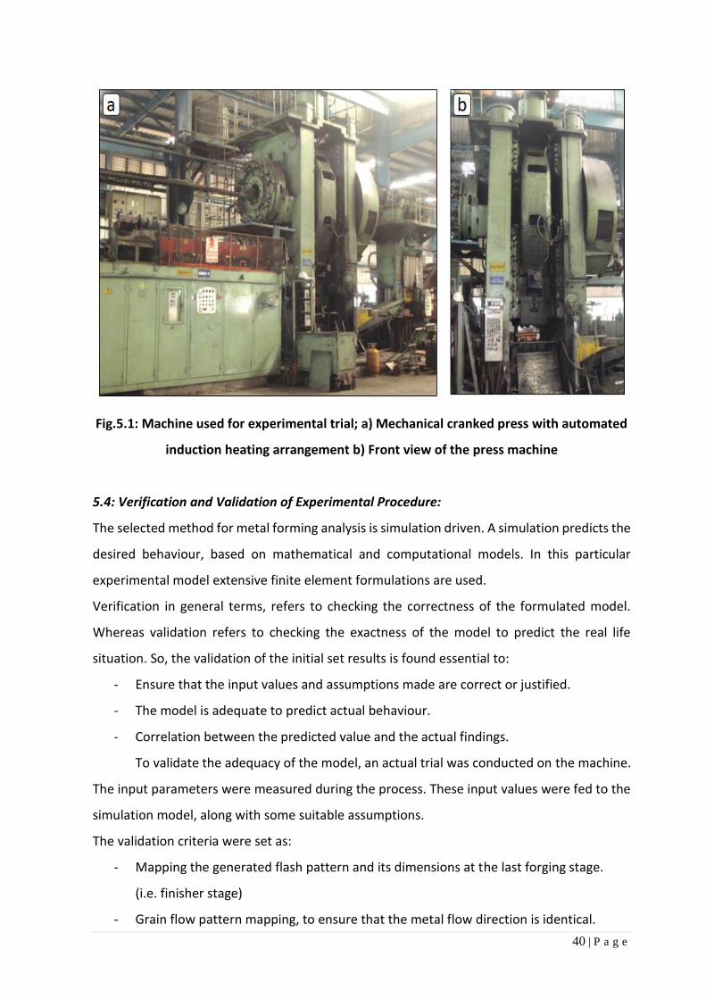
5.5: Stage-wise Simulation Results:
The simulation results are interpreted by using post-processor. The output parameters
can be customised to suit the problem definition and to improve the overall understanding of
the process. The stage wise deformation and the resulting metal flow behaviour are shown in
Fig.5.4-5.6. It captures the transformation of simple billet geometry; into the complex shaped
component along with the effective stress distribution during the process.
Fig.5.4: (a-c) Step wise simulation result of upsetting stage; Effective stress plot

45 | P a g e
Fig.5.5: (a-f) Step- wise simulation result of blocker stage; Effective stress plot
Fig.5.6: (a-c) Step wise simulation result of finisher stage; Cut sectional view
The result shows that, the metal flow at the finisher stage is limited; whereas it is maximum
at the blocker stage. This is desirable and in line with the criteria for die design adopted.
The predicted load stroke curve and temperature distribution for the blocker stage is shown
as a sample Fig.5.7. An upsurge in temperature (to 1280oC) is observed, at the end of
deformation process from initial input value (to 1250oC). This can be attributed to the
conversion of mechanical work into heat energy, during the process of deformation.

46 | P a g e
Fig.5.7: Simulation predicted results for load and temperature. (a – Load stroke graph for the process; b - Temperature distribution plot)
The result obtained from the solver, can also be transformed into different forms of output
such as effective stress, effective strain, velocity distribution etc. For this study, we will be
focusing our attention to the forming load.
5.6: Determination of Die Filling during Analysis
In closed die forging process, the component shape and dimensions are derived from the die
cavity. Therefore, as an essential requirement, the die cavity should be completely filled.
In FE analysis, interaction at the face of die and workpiece is modelled using contact elements.
The load transfer and interaction behaviour at the interface is taken care by such elements.
So, the behaviour of the contact elements at final step ensures the filling of the die. A typical
contact pattern of such elements is shown in Fig.5.8. For all the experimental trials, the die
filling is ensured at the final step.
Fig.5.8: Contact element display showing the complete die filling. (a - Contact pattern of top die shown in green coloured dots; b - Contact pattern
of the bottom die is shown in blue coloured dots)
a b

47 | P a g e
The material and the die set used for the actual experiment is shown in Fig.5.9.
Fig.5.9: Actual set up showing billet and die used for experimental trial a) Input billet material, b) Blocker bottom die, c) Blocker top die
The image of actual component is shown in Fig.5.10.
Fig.5.10: a-c Different views of the actual component without flash
5.7: Experimental Details Aiming Design of Experiments:
As discussed earlier, the closed die hot forging process has many process variables. As
an outcome of the process, the forging load can be considered as a vital response
characteristic. The forging load as an output parameter:
- Decides the selection of equipment for the process.
- Affects equipment and die wear characteristic, including die life.
- Influences the economy of manufacturing
It is evident that the lower forging load is desired in the processing cycle.
Considering the component selected and with defined set of workpiece material, machine
specification, die design; the following factors are expected to mostly influence process
characteristic:
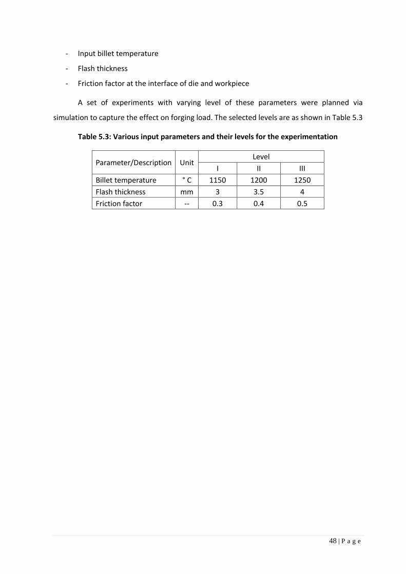
48 | P a g e
- Input billet temperature
- Flash thickness
- Friction factor at the interface of die and workpiece
A set of experiments with varying level of these parameters were planned via
simulation to capture the effect on forging load. The selected levels are as shown in Table 5.3
Table 5.3: Various input parameters and their levels for the experimentation
Parameter/Description Unit Level
I II III
Billet temperature ° C 1150 1200 1250
Flash thickness mm 3 3.5 4
Friction factor -- 0.3 0.4 0.5

49 | P a g e
5.8: Experimental Results:
Experimental run were performed considering different combination of levels and the
corresponding predicted forging load value for both blocker and finisher stage were recorded.
The summary of the simulation trial is shown in Table.5.4.
Table 5.4: Experimental finding of the forging load at different levels of input parameter
RUN
A
B
C A B C
Upsetting Stage Forging Load
Blocker Stage Forging Load
Finisher Stage Forging Load
Temp
(°C) Flash Thk
(mm) Friction
(in N) (in N) (in N)
1 1 1 1 1150 3 0.3 3.29E+05 9.21E+06 7.88E+06
2 1 1 2 1150 3 0.4 3.30E+05 9.35E+06 8.07E+06
3 1 1 3 1150 3 0.5 3.31E+05 1.03E+07 8.62E+06
4 1 2 1 1150 3.5 0.3 -- 7.04E+06 6.01E+06
5 1 2 2 1150 3.5 0.4 -- 8.22E+06 6.88E+06
6 1 2 3 1150 3.5 0.5 -- 8.58E+06 7.18E+06
7 1 3 1 1150 4 0.3 -- 6.17E+06 5.01E+06
8 1 3 2 1150 4 0.4 -- 6.95E+06 5.58E+06
9 1 3 3 1150 4 0.5 -- 8.03E+06 6.49E+06
10 2 1 1 1200 3 0.3 2.87E+05 8.00E+06 6.69E+06
11 2 1 2 1200 3 0.4 2.89E+05 8.57E+06 7.12E+06
12 2 1 3 1200 3 0.5 2.92E+05 9.38E+06 7.85E+06
13 2 2 1 1200 3.5 0.3 -- 6.52E+06 5.52E+06
14 2 2 2 1200 3.5 0.4 -- 7.27E+06 6.10E+06
15 2 2 3 1200 3.5 0.5 -- 8.27E+06 6.89E+06
16 2 3 1 1200 4 0.3 -- 5.63E+06 4.82E+06
17 2 3 2 1200 4 0.4 -- 5.89E+06 5.01E+06
18 2 3 3 1200 4 0.5 -- 6.87E+06 5.79E+06
19 3 1 1 1250 3 0.3 2.46E+05 6.53E+06 5.64E+06
20 3 1 2 1250 3 0.4 2.47E+05 7.16E+06 6.12E+06
21 3 1 3 1250 3 0.5 2.48E+05 7.48E+06 6.44E+06
22 3 2 1 1250 3.5 0.3 -- 5.89E+06 5.08E+06
23 3 2 2 1250 3.5 0.4 -- 6.13E+06 5.31E+06
24 3 2 3 1250 3.5 0.5 -- 6.89E+06 5.94E+06
25 3 3 1 1250 4 0.3 -- 4.85E+06 4.32E+06
26 3 3 2 1250 4 0.4 -- 5.21E+06 4.62E+06
27 3 3 3 1250 4 0.5 -- 5.88E+06 5.20E+06

50 | P a g e
CHAPTER 6
ANALYSIS OF EXPERMENTAL WORK
This chapter includes the analysis of data generated from the experimental work performed.
After validating the process, the experimental trials are done in FE method based simulation
software DEFORM-3D. The major focus was to:
- Understand the metal flow behaviour.
- Find out the effect of selected parameter and their significance.
- Identify combination of parameters to achieve lowered forging load.
6.1: Data Analysis on Effect of Parameters:
It has been observed that the blocker stage is most crucial in the multi stage forging
process; as the maximum metal flow take place at this stage. Hence, this stage can be
identified as the ideal stage for optimization. The forging load at the blocker stage with various
combinations of input parameters are plotted graphically to note the effect of parameters.
The effect of variation of temperate in the input billet, at constant flash thickness and friction
factor is shown in Fig.6.1.
Fig.6.1: Effect of variation of billet temperature

51 | P a g e
It is observed that, forging load at blocker stage is reduced drastically with the increase in
input billet temperature. This behaviour can be explained from the following facts:
- The value of flow stress, which accounts for the metal flow; reduces with increase in
temperature.
- The reduction in flow stress values, causes better metal flow due to lesser resistance.
This in in turn, reduces the forging load requirement at higher temperature.
The effect of variation of flash thickness, at constant billet temperature and friction factor is
shown in Fig.6.2
Fig.6.2: Effect of variation of flash thickness
It is noticed that the forging load in the blocker stage is also reduced with increase in flash
thickness. This behaviour can be explained from the following facts:
- A lesser value in flash thickness adds up the extra squeezing load at the flash land area.
- A higher load is required in the transverse direction; when the excess material tries to
escape from the die cavity, after the complete filling stage is reached. The lesser
available cross section will create a restriction to flow and in terms increase the
demand of additional load.
Hence, it is desirable to have a flash thickness in positive side to reduce the forging load. It
should also be noted that, a very high value of flash thickness is also not desired, as it can

52 | P a g e
restrict the complete filling of the die. Higher flash thickness can also cause difficulties in
trimming stage and leaves a deep trim mark on the finished component; apart from adding to
the cost due to consumption of a greater amount of input material (billet) for the same size
of the finished product.
The effect of variation of friction factor, at constant billet temperature and flash
thickness is shown in Fig.6.3.
Fig.6.3: Effect of variation of friction factor
It is observed that the forging load at blocker stage is increasing with the increase in
frictional value. This behaviour can be explained from the following facts:
- The interface friction between the die and the workpiece restricts the metal flow,
causing the requirement for additional force to overcome, in comparison to an ideal
frictionless situation.
- It also causes variation in the distribution of applied load to the workpiece.
So, the overall forging load requirement increases, at higher values of friction factor.

53 | P a g e
6.2: Design of Experiment Trial
In order to determine the most desirable combination of parameters along with the
significance of each, Taguchi method is adopted. Unlike other design of experiment tools,
Taguchi method adopts the orthogonal array (OA) approach [11, 12]. This method is effective
and more popular in industries, as the OA approach considers the entire parameters with
lesser number of trials or experiments, as compared to other methods. The method considers
both controlled and noise factors in the design.
Additionally, the Taguchi method uses the loss function approach for the measurement of the
performance characteristics deviating from the desired value. These values of loss functions
are converted to S/N (Signal to noise) ratio.
Broadly, three methods are available for of calculating the S/N ratio, and the appropriate
method is decided based on end objective or outcome desired. Considering the forging load
as response, minimisation criteria (Smaller is better) is selected.
The formula for calculating the S/N ratio in decibel is as follows: (Smaller is better)
S/N Ratio = −10log (1
𝑛∑ 𝑦𝑖
2𝑛𝑖=1 ) …… (Eq.6.1)
Where,
�̅� = average of observed data
𝑦 = is observed data
𝑠𝑦2 =Variance of y
n = no. of observations
It should be noted that, the larger value of S/N ratio indicates better performance
characteristics. So the desired level of the process parameters is identified by the highest value
of S/N ratio.
For the data analysis, considering three factors with three levels, a L9 orthogonal array was
constructed and the S/N ratios were calculated considering the “Lower is better criteria”. The
L9 orthogonal array is shown in Table 6.1.

54 | P a g e
Table 6.1: L9 Orthogonal array with parameters, response and calculated S/N Ratio
The main effect plot for S/N ratio, for billet temperature, flash thickness and friction
factor are plotted graphically as shown in Fig.6.4.
Run Reference Combination of factors Blocker load
(N)
S/N Ratio
No A B C Temp.
Flash Thk
Friction
1 1 1 1 1150 3 0.3 9.21E+06 -139.285
2 1 2 2 1150 3.5 0.4 8.22E+06 -138.297
3 1 3 3 1150 4 0.5 8.03E+06 -138.094
4 2 1 2 1200 3 0.4 8.57E+06 -138.660
5 2 2 3 1200 3.5 0.5 8.27E+06 -138.350
6 2 3 1 1200 4 0.3 5.63E+06 -135.010
7 3 1 3 1250 3 0.5 7.48E+06 -137.478
8 3 2 1 1250 3.5 0.3 5.89E+06 -135.402
9 3 3 2 1250 4 0.4 5.21E+06 -134.337

55 | P a g e
Fig.6.4: Main effect plots for S/N ratio for different parameters
The graphical representation reveals that the combination (3, 3, 1) is the best combination for
getting lowest forging load. This corresponds to forging at 1250 degree billet temperature, 4
mm die gap with 0.3 operating friction factor. The prediction is matching with the
experimental trial.
For establishing the significance of each parameter, a response table for S/N ratio is
constructed. The mean S/N ratio at each level is calculated. The difference between the
maximum and minimum is termed as Delta. The calculated value of delta for the different

56 | P a g e
parameters are compared to find out the significance of each parameter. The response table
for S/N ratio along with rank is shown in Table.6.2.
Table 6.2: Response table for S/N Ratio
Level Temperature Flash Thickness Friction Factor
1 -138.6 -138.5 -136.6
2 -137.3 -137.3 -137.1
3 -135.7 -135.8 -138.0
Delta 2.8 2.7 1.4
Rank 1 2 3
It was earlier observed that the temperature, flash thickness and friction are crucial
parameters for the process and its variation has a major impact on the forging load. From the
response table, it can be concluded that, the temperature of the input billet is the most
significant parameter followed by flash thickness.

57 | P a g e
CHAPTER 7
CONCLUSION AND SCOPE FOR FUTURE WORK
7.1: Conclusion:
In this work, an automotive driveline component (Flange Yoke) is taken as a reference sample,
to study the metal forming behaviour during closed die forging. The effect of selected input
(forging) parameters on forging load is determined. The Taguchi method is used to find out
the best possible combination for the desired response. The conclusion drawn from the work
is as follows:
I. Finite element method is quite suitable for analysing complex metal forming
characteristics in a closed die hot forging process.
II. Using the FE method, other phenomena associated with metal forming, such as heat
generation due to deformation, heat transfer etc. can be coupled with the basic
deformation analysis, so that the solution is close to the real life.
III. A good amount of agreement is observed during validation of the FE output with actual
manufacturing data, in terms of flash pattern and dimension prediction.
IV. The metal flow prediction agrees well with the grain flow in actual component.
V. The die filling prediction in terms of contact element behaviour is found useful in real
life situation.
VI. The billet temperature, flash thickness and friction are found to have a significant effect
on the forging load. Among the three, the temperature of the input billet is found to be
the most significant parameter followed by flash thickness and friction factor, in that
order.

58 | P a g e
7.2: Scope for Future Work:
The primary aim of the present work was to develop a methodology for the analysis of real
life components processed via closed die hot forging process. With level of understanding
developed in this work, the future scope of work can be envisaged as follows:
I. The aspects associated with design parameters for forging can be studied for effects on
response.
II. Develop prediction for prediction of the time and die-gap at which filling of cavity takes
place so that over-squeezing (hence avoidable extra work) is minimized.
III. Predict temperature rise in work-piece (through adiabatic heat) so that energy of
heating can be reduced.
IV. Optimum blocker stage design based on FE analysis.
V. Die life prediction and improvement, based on die stress analysis.
VI. Other complex component shapes can be undertaken for metal flow analysis.
VII. Forging stage reduction in complex components processed in multiple stages.

59 | P a g e
REFERENCES [1] T. Altan, G.Ngaile and G.Shen (2004) Cold and Hot Forging: Fundamental and
Application, 1st ed., ASM International.
[2] ASM Metals Hand Book, Metal working: Bulk Forming (2005) Vol.14A, ASM
International.
[3] W.H. Hosford, (2011) Metal Forming: Mechanics and Metallurgy, 4th ed., Cambridge
University Press.
[4] G.E. Dieter (1988), Mechanical Metallurgy, SI Edition, McGraw Hill Book Company.
[5] G.E. Dieter, H.A. Kuhn and S.L. Semiatin (2003) Handbook of Workability and Process
Design, ASM International.
[6] S. Kobayashi, S.I. Oh and T. Altan (1989) Metal Forming and the Finite-Element Method,
Oxford University Press.
[7] A. Thomas, Forging Handbook: Die Design (1995) Drop Forging Research Association Ltd
[8] S. N. Prasad, R. Sharan and N.P. Saksena (1982) Forging Die Design and Practices, S.
Chand and Co. Ltd.
[9] R. L. Taylor, O.C. Zienkiewicz and J.Z. Zhu (2005), The Finite Element Method: Its Basic
and Fundamental, 6th ed.,Elsevier Butterworth-Heinemann.
[10] R.D. Cook, D.S. Malkus, M.E. Plesha and R.J. Witt (2012) Concept and Applications of
Finite Element Analysis, 4th ed., Wiley India Pvt. Ltd.
[11] M. S. Phadke (2008) Quality engineering using robust design, Pearson Education Ltd
[12] K. K. Krishnaaiah and P. Shahabudeen (2012) Applied Design of Experiments and Taguchi
Methods, Prentice Hall India.
[13] B. Tomov, R. Radev and V. Gagov (2004) Influence of flash design upon process
parameters of hot die forging, Journal of Materials Processing Technology, Vol. 157–158,
pp. 620-623
[14] M. Sedighi and S. Tokmechi (2008) A new approach to preform design in forging process
of complex parts, Journal of Materials Processing Technology, Vol. 197, pp. 314-324.
[15] F. Fereshteh-Saniee and A.H. Hosseini (2006) The effects of flash allowance and bar size
on forming load and metal flow in closed die forging, Journal of Materials Processing
Technology, Vol. 177, pp. 261-265.
[16] A. R. Ab-Kadir et. al (2009) Effect of corner radius and friction parameters on the
optimization of cold forging die design, Modern Applied Science, Vol.3, pp. 177-189.

60 | P a g e
[17] Y.C. Lin, M.S. Chen and J. Zhong (2008) Effect of temperature and strain rate on the
compressive deformation behaviour of 42CrMo steel, Journal of Materials Processing
Technology, Vol. 205, pp. 308-315.
[18] T.C. Grobaski, B. Mehta and J. Gunasekera, Preliminary investigation into the effects of
friction, work-piece temperature, and stroke speed in hot forging die life, Dept. of
mechanical Engineering, Ohio University.
[19] K. Osakada (2010) History of plasticity and metal forming analysis, Journal of Materials
Processing Technology, Vol. 210, pp. 1436-1454.
[20] S.I. Oh, W.T. Wu, J.P. Tang, and A. Vedharayagam (1991) Capabilities and applications of
FEM code DEFORM. The perspective of the developer, Journal of Material processing
Technology, Vol.27, pp. 25-42.
[21] B.I. Tomov, V.I. Gagov and R.H. Radev (2004), Numerical simulations of hot die forging
processes using finite element method, Journal of Materials Processing Technology, Vol.
153–154, pp. 352-358.
[22] A.D. Santos, J.F. Duarte, A. Reis, B. da Rocha, R. Neto and R. Paiva (2001) The use of finite
element simulation for optimization of metal forming and tool design, Journal of
Materials Processing Technology, Vol. 119, pp. 152-157.
[23] K.S. Park, Chester J. VanTyne and Y.H. Moon (2007) Process analysis of multistage
forging by using finite element method, Journal of Materials Processing Technology, Vol.
187–188, pp. 586-590
[24] T. Gangopadhaya, R.K. Ohdar, D.K. Pratihar and I. Basak (2010) Three dimensional finite
element analysis of multi-stage hot forming of railway wheel, International Journal of
Advanced Manufacturing Technology, Vol.53, pp. 301-312.
[25] G.D. Satish, N.K. Singh and R.K. Ohdar (2008) Preform optimization of pad section of
front axle beam using DEFORM, Journal of Materials Processing Technology, Vol. 203,
pp. 102-106.
[26] M. Hirscvogel and H.V. Dommelen (1992) Some applications of cold and warm forging,
Journal of Materials Processing Technology, Vol. 35, pp. 343-356.
[27] H. Kim, K. Sweeney and T. Altan (1994) Application of computer aided simulation to
investigate metal flow in selected forging operations, Journal of Materials Processing
Technology, Vol. 46, pp. 127-154.
[28] Deform Software User Manual (2011) Scientific Forming Technologies Corporation.