study of the tool path generation method of an ultra
TRANSCRIPT

Study of The Tool Path Generation Method of anUltra-Precision Spherical Complex Surface Basedon a Five-Axis Machine ToolTianji Xing
Harbin Institute of TechnologyXuesen Zhao ( [email protected] )
Harbin Institute of Technology https://orcid.org/0000-0001-5460-0683Zhipeng Cui
Harbin Institute of TechnologyRongkai Tan
East China Jiaotong UniversityTao Sun
Harbin Institute of Technology
Research Article
Keywords: Tool path generation method, Five-axis machining, Spherical complex surface, Ultra-precision,Milling
Posted Date: February 10th, 2021
DOI: https://doi.org/10.21203/rs.3.rs-167042/v1
License: This work is licensed under a Creative Commons Attribution 4.0 International License. Read Full License

1
Study of the Tool Path Generation Method of an Ultra-Precision Spherical
Complex Surface Based on a Five-Axis Machine Tool
Tianji Xing a, Xuesen Zhao a, *, Zhipeng Cui a, Rongkai Tan b, Tao Sun a
a Center for Precision Engineering, Harbin Institute of Technology, Harbin, China
b School of Mechatronics & Vehicle Engineering, East China Jiaotong University, Nanchang, China
Keywords:
Tool path generation method; Five-axis machining; Spherical complex surface; Ultra-precision; Milling
Abstract
The improvement of ultra-precision machining technology has significantly boosted the demand for the
surface quality and surface accuracy of the workpieces to be machined. However, the geometric shapes of
workpiece surfaces cannot be adequately manufactured with simple plane, cylindrical, or spherical
surfaces because of their different applications in various fields. In this research, a method was proposed
to generate tool paths for the machining of complex spherical surfaces based on an ultra-precise five-axis
turning and milling machine with a C-Y-Z-X-B structure. Through the proposed tool path generation
method, ultra-precise complex spherical surface machining was achieved. First, the complex spherical
surface model was modeled and calculated, and then it was combined with the designed model to
generate the tool path. Then the tool paths were generated with a numerically controlled (NC) program.
Based on an ultra-precision three-coordinate measuring instrument and a white light interferometer, the
machining accuracy of a workpiece surface was characterized, and t1he effectiveness of the provided tool
path generation method was verified. The surface roughness of the machined workpiece was less than 90
* Corresponding Author.
Email Address: [email protected]

2
nm. Furthermore, the surface roughness within the spherical region appeared to be less than 30 nm. The
presented tool path generation method in this research produced ultra-precision spherical complex
surfaces. The method could be applied to complex spherical surfaces with other characteristics.
1 Introduction
Ultra-precision machining technology has been widely used in the biomedicine, aerospace, defense,
and electronic communication technology industries [1]. Because of their different applications in various
fields, the geometric shapes and surface morphologies of machined surfaces have become more
complicated. Improving the surface shape accuracy and roughness of a machined workpiece is significant,
because these factors have a great influence on the performance of a workpiece. A complex surface
requires the use of high precision calculations and encompasses both functional and aesthetic effects; it is
a combination of a curved surface formed by multiple curvatures [2-3]. Typical complex surfaces include
aspheric surfaces, free-form surfaces, and special-shaped surfaces [4].
The machining of complex surfaces can be achieved by using three-axis turning machining.
Representative turning machining methods include single point diamond turning (SPDT), fast tool servo
(FTS) turning, and slow tool servo (STS) turning [5]. At present, SPDT is commonly used in the
manufacturing of ultra-precision spherical and aspherical surfaces [6]. However, traditional SPDT cannot
meet machining requirements because the curvature of the spherical surface is larger than the common
optical curved surface [7-8]. FTS turning has the characteristics of a high motion frequency response,
easy resonance, and a short stroke [9-11]. However, it is not suitable for machining spherical workpieces
with a certain degree of rotation. STS turning is significantly affected by the inertia of a machine tool
slide and the response speed of a motor, and the dynamic response speed of a machine tool is low, which
3
would not be suitable for the machining of a complex spherical surface [12,13]. Compared with turning,
multi-axis milling is more suitable for the machining of spherical complex surfaces with millimeter-scale
characteristics, such as pits and round chamfers [14,15]. Multi-axis milling requires more than three axes
to work together. Each axis generally includes a linear axis and a rotary axis. The linear axis and the
rotary axis work together to satisfy the requirements of machining spherical complex surfaces in different
orientations [16,17]. However, due to the increase in the motion of the axes, the sources of error also
increase. Therefore, it is necessary to ensure the accuracy of the important performance indicators of the
machine tool and provide a stable processing environment [18,19]. Due to the above-mentioned reasons,
the machining method employed in this research was based on ultra-precision turning combined with
multi-axis milling. Multi-axis milling can be used to machine complex and high steepness surfaces
[20,21].
Furthermore, the generation of tool paths plays an important part in complex surface machining. For
workpieces with complex shapes, the key to tool path generation is determining how to solve interference
processing. The generation of tool paths determines the actual movement paths and pose states in the
computer numerical controlled (CNC) machining process. Additionally, for the same workpiece, using
different tool path generation methods could thus cause obvious differences in the machining efficiency
and accuracy.
Numerous research studies have been conducted to solve the tool path generation problems. Yuan et
al. [22] proposed a tool vibration path generation strategy based on the working principle of the double
frequency vibration cutting method. Kong et al. [23] proposed the processing of composite free-form
surfaces by combining the hybrid processing technology of a slow sliding servo and a fast tool servo. The

4
machining process for this hybrid tool servo was explained, and the tool path generation was presented.
Koyama et al. [24] developed a computer aided manufacturing (CAM) system in ultra-precision
micromachining to assist operators with settings. From the simulation result, it was found that the CAM
system was effective in producing micro parts easily and accurately. Chen et al. [25,26] proposed a new
method to model complex surfaces based on the recursive subdivision theory. This method could deal
with a complex surface with an arbitrary topological structure that had initial mesh controls. It had a high
calculation efficiency, the modeling results were ideal, the numerical control interpolation accuracy of the
complex surface was very high, and its error was controllable. Huang et al. [27] and Chen et al. [28]
generated tool paths from geometrical calculations considering lens designs, tool geometries, and roller
parameters. Gao et al. [29] discussed the methodology for the development of the tool path generator for a
progressive lens. Using the model of the freeform surface, which represents a double cubic B-spline
surface, the method of changing parameters was used to calculate the numerically controlled (NC)
machining tool path. Brecher et al. [30] presented the layout of a tool path calculation based on the
Non-Uniform Rational B-Splines (NURBS) data format. In addition, the interfaces, the hardware, and the
software for the realization of a NURBS based control unit for Fast Tool Servo turning and local
corrective polishing operations were described.
Software for generating complex curved tool paths is widely used, and popular programs include
UG [31-33], PRO/E [34], and PowerMILL [35]. The main advantage of commercial software is that it can
automatically generate tool paths flexibly according to the shape of a rough workpiece and a machining
target. However, ultra-precision machining requires tool paths with step lengths, spacing, and feed rates
with small sizes. When these commercial software programs are employed, they can be time-consuming

5
and difficult to use. Therefore, in this research, the use of programming software to design a complex
spherical surface that needed to be processed was considered, and a small spacing was set for the tool
path.
In summary, it is necessary to study a method for generating the tool paths of spherical complex
surfaces. In this research, a method was proposed for the generation of tool paths for the machining of
complex spherical surfaces, and a golf-ball-like spherical surface served as a research model for the
five-axis machining of complex curved surfaces. The reasons for this are as follows. First, such a method
would be useful in fluid mechanics applications [36,37]. Second, it can generate representative spherical
complex surfaces. In this research, the golf-like spherical surface machining was based on an
ultra-precision five-axis turning and milling machine.
2 Machining objects and equipment
2.1 Machining objects
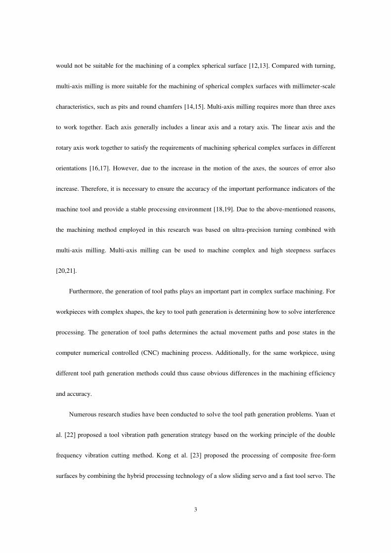
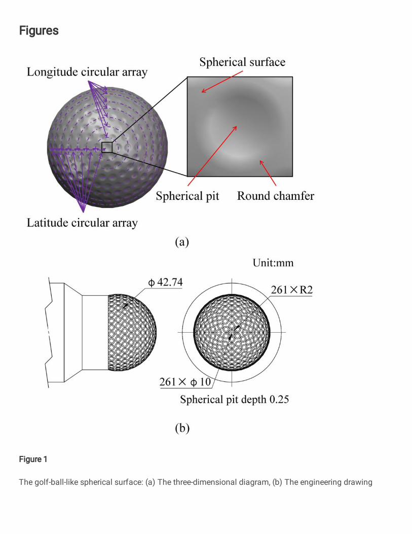
We used a golf-ball-like spherical surface as the machining object. The main body of the
golf-ball-like spherical surface was a sphere, and the spherical pits were arranged regularly on its surface.
As shown in Fig. 1(a), the size, depth, the number of pits, different complex shapes, and different area
types were all important geometric parameters that significantly influenced the golf-ball-like spherical
surface. We found that there were round chamfers at the junction of the pit and the sphere.
6
Fig. 1. The golf-ball-like spherical surface: (a) The three-dimensional diagram, (b) The engineering
drawing
In this research, the spherical diameter of the machined workpiece was set to 42.74 mm. The pits
were distributed at a distance of 10° along the latitude line of the sphere, and the longitude circular array
quantity of each latitude line was set. The depth of each pit was 0.25 mm, the diameter of the pit surface
was 10 mm, and the pit and the spherical surface had round chamfers with a radius of 2 mm, as shown in
Fig. 1(b).
The main characteristics of the studied golf-ball-like spherical surface were small sizes, high surface
7
shape accuracy, and high surface machining quality requirements. According to the machining
requirements of the workpiece, the manufacturing process was a typical precision or ultra-precision
machining process. Therefore, machining this workpiece required ultra-precision precision machine tools,
as well as strict control of the machining technology and the environment. Additionally, high precision
tool path generation methods were strongly needed. The key technology of tool path generation included
the step length selection, step distance selection, and interference avoidance.
2.2 Experimental set-up
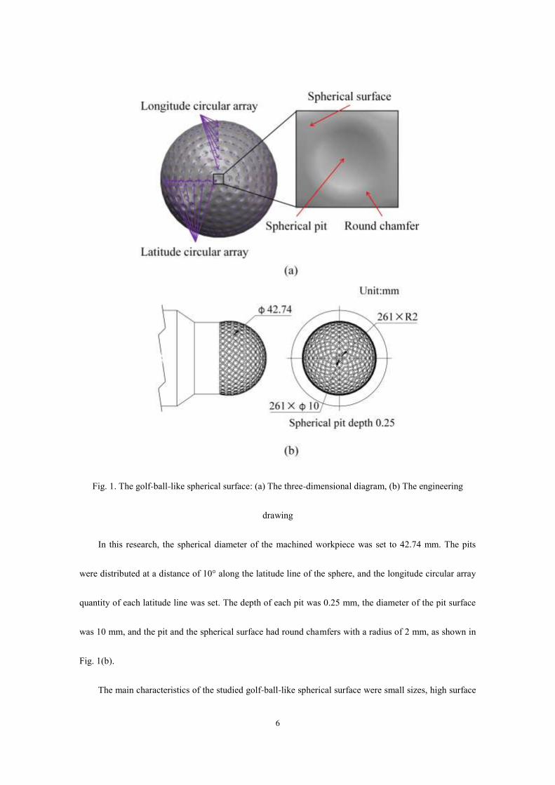
This research was based on a five-axis ultra-precision turning and milling compound machine tool
developed by the Center for Precision Engineering of the Harbin Institute of Technology. The
ultra-precision five-axis machine tool had a C-Y-Z-X-B structure, as shown in Fig. 2. The machine tool
consisted of three linear axes, including an X axis, Y axis, and Z axis, and two rotary axes, including a B
axis and a C axis. The X axis and the Z axis were located on the base of the machine tool. The X axis and
the B axis constituted the tool branch of the machine tool. The Z axis, Y axis, and C axis constituted the
workpiece branch of the machine tool.

8
Fig. 2 Ultra-precision five-axis CNC machine tool
The machine tool adopted the open loop CNC system of a UMac platform with independent and
controllable features. It could independently add functions according to the actual processing
requirements and achieve the RTCP (Rotational Tool Center Point) function through five-axis
collaborative work [38,39]. It was able to operate in conjunction with an optical microscope and a contact
probe. The main parameters of the machine tool are shown in Table 1.
Table 1
Main parameters of ultra-precision five-axis turning and milling machine tool
The main parameters Error range
X/Y/Z guide rail travel range 300 mm/100 mm/200 mm
X/Y/Z guide rail straightness <0.2 μm total travel
X/Y/Z guide rail positioning accuracy <±0.5 μm total travel
X/Y/Z guide rail repeated positioning accuracy <±0.3 μm total travel
Verticality error between B-axis and X-axis <2″
Verticality error between B axis and Z axis <2″
Angle between the C axis and Z axis <2″
Y-axis and Z-axis pitch angle <1″
B-axis angular positioning accuracy <±1″
3 Methodology
The process of machining a golf-ball-like spherical surface was divided into turning and milling. In
the machining process, the spherical surface was turned first, and then the pits on the golf-ball-like
9
spherical surface were milled.
3.1 Spherical surface turning
The geometry of the cutting part of the diamond tool affected the machining quality of the workpiece
surface. A suitable tool arc radius and center envelope angle ensured that the tool arc could cut every
point on the ideal curved surface. Proper rake and back angles prevented the diamond tool from
over-cutting the machined surface during the machining process. When the required cutting angle of the
curved surface was larger than the center envelope angle of the tool, the swing of the B axis needed to
satisfy the machining. Therefore, when editing the tool path, it was necessary to consider the motion path
of the X, Z, and B three-axes linkage, and the Y axis was used for the centering adjustment and height
adjustment.
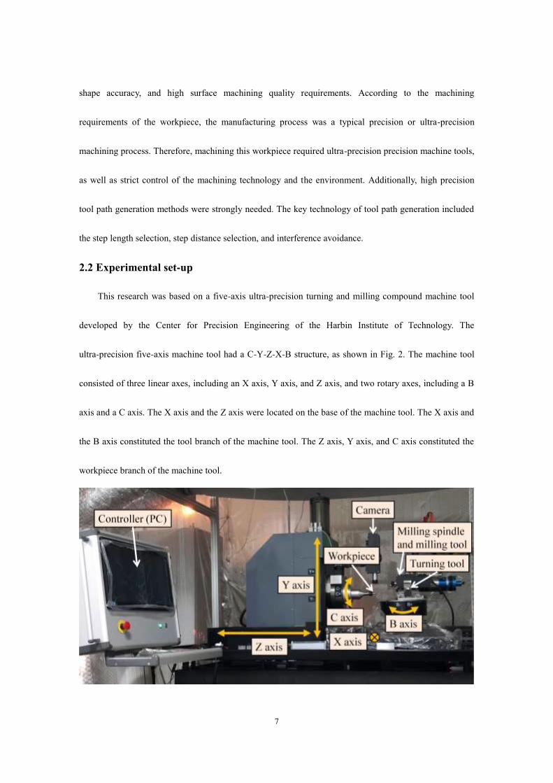
Programming software was used to generate the cutting path. According to the surface shape, the X,
Z, and B coordinates corresponding to the cutting points were obtained. For spherical surfaces with the
nature of a cyclotron, Archimedes spirals were suitable for generating the tool paths. Common point
definition methods were divided into an equidistance method and an equiangular method, as shown in Fig.
3.
Fig. 3 Definition method between spiral points: (a) Equidistance method; (b) Equiangular method

10
Fig. 3(a) shows that the number of points on each spiral in the equiangular method was the same.
The density of the points on the spiral was inversely proportional to the radius. This meant that the
distribution of the points near the edge of the surface was relatively sparse, while the distribution of
points near the center of the surface was relatively dense. Fig. 3(b) shows that in the equidistance method,
the arc length between two adjacent points on each spiral was equal. The distribution of points near the
edge of the surface was relatively dense, and the distribution of points near the center of the surface was
relatively sparse. Considering the characteristics of these two methods, we selected the equiangular
method for processing the spherical surface because the central part needed more points. The calculation
of the equiangular spiral method is shown in Eq. (1). 𝑥𝑖 = cos(𝜔𝑡𝑖) ∗ sin(𝜌𝑡𝑖) ∗ 𝑅𝑦𝑖 = sin(𝜔𝑡𝑖) ∗ sin(𝜌𝑡𝑖) ∗ 𝑅𝑧𝑖 = cos(𝜔𝑡𝑖) ∗ 𝑅 (1)
In Eq. (1), (𝑥𝑖 , 𝑦𝑖 , 𝑧𝑖) are the coordinates of the cutting point numbered 𝑖, ω is the total radians of
the X-Y plane, ρ is the total radian of the Z direction, and 𝑡𝑖 is between 0 and 1. The distance was
determined by the distance ∆𝑡 between 𝑡𝑖−1 and 𝑡𝑖. Since the workpiece was a spherical surface, the B
axis and the spindle were required to rotate with the position of the machined surface. The tool axis was
aligned with the center of the sphere to define the B axis and the spindle, which required the calculation
of the normal vector of the cutting point. The spherical formula is shown in Eq. (2). The derivatives of x,
y, and z in Eq. (2) were calculated as shown in Eq. (3).
𝐹(𝑥, 𝑦, 𝑧) = 1 − 𝑥2𝑅2 − 𝑦2𝑅2 − 𝑧2𝑅2 (2)
�⃑�= (2 ∗ 𝑥𝑖)/𝑅2 �⃑�= (2 ∗ 𝑦𝑖)/𝑅2𝑧= (2 ∗ 𝑧𝑖)/𝑅2 (3)
First, the corresponding homogeneous transformation of Eq. (4) into Eq. (5) was organized, and then
11
�⃑�,�⃑�,𝑧 were substituted into Eq. (5) to solve the corresponding B and C axis coordinates.
[cos 𝐶 − sin 𝐶 0 0sin 𝐶 cos 𝐶 0 00 0 1 00 0 0 1] [− sin𝐵0cos 𝐵0 ]=[�⃑��⃑�𝑧0] (4)
�⃑� = −cos 𝐶 sin 𝐵�⃑� = −sin 𝐶 sin 𝐵 𝑧 = cos 𝐵 (5)
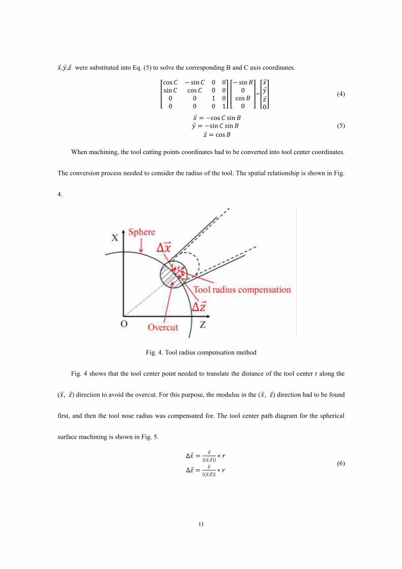
When machining, the tool cutting points coordinates had to be converted into tool center coordinates.
The conversion process needed to consider the radius of the tool. The spatial relationship is shown in Fig.
4.
Fig. 4. Tool radius compensation method
Fig. 4 shows that the tool center point needed to translate the distance of the tool center r along the
(�⃑�, 𝑧) direction to avoid the overcut. For this purpose, the modulus in the (�⃑�, 𝑧) direction had to be found
first, and then the tool nose radius was compensated for. The tool center path diagram for the spherical
surface machining is shown in Fig. 5.
∆�⃑� = 𝑥|(𝑥,𝑧)| ∗ 𝑟∆𝑧 = 𝑧|(𝑥,𝑧)| ∗ 𝑟 (6)
12
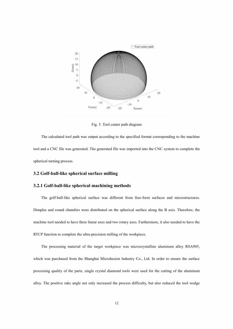
Fig. 5. Tool center path diagram
The calculated tool path was output according to the specified format corresponding to the machine
tool and a CNC file was generated. The generated file was imported into the CNC system to complete the
spherical turning process.
3.2 Golf-ball-like spherical surface milling
3.2.1 Golf-ball-like spherical machining methods
The golf-ball-like spherical surface was different from free-form surfaces and microstructures.
Dimples and round chamfers were distributed on the spherical surface along the B axis. Therefore, the
machine tool needed to have three linear axes and two rotary axes. Furthermore, it also needed to have the
RTCP function to complete the ultra-precision milling of the workpiece.
The processing material of the target workpiece was microcrystalline aluminum alloy RSA905,
which was purchased from the Shanghai Microhesion Industry Co., Ltd. In order to ensure the surface
processing quality of the parts, single crystal diamond tools were used for the cutting of the aluminum
alloy. The positive rake angle not only increased the process difficulty, but also reduced the tool wedge
13
angle. All these factors could lead to a shortened tool life. Considering the above reasons, it was more
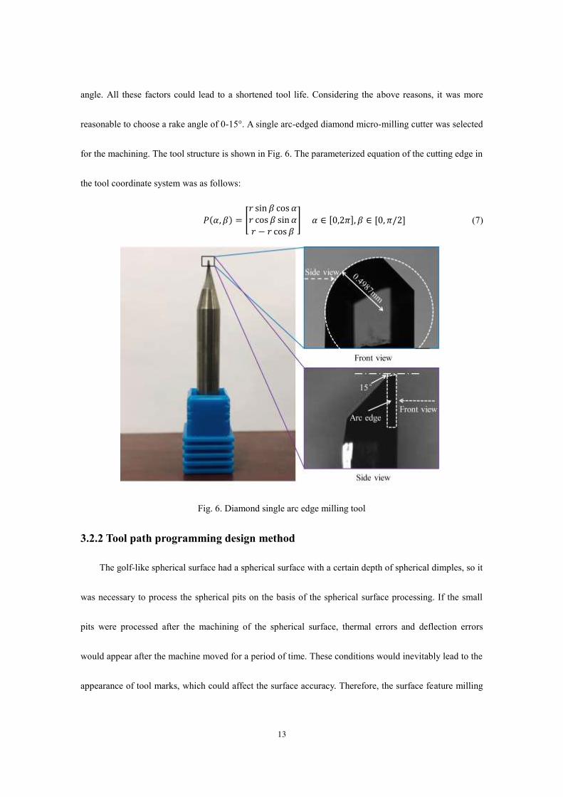
reasonable to choose a rake angle of 0-15°. A single arc-edged diamond micro-milling cutter was selected
for the machining. The tool structure is shown in Fig. 6. The parameterized equation of the cutting edge in
the tool coordinate system was as follows:
𝑃(𝛼, 𝛽) = [𝑟 sin 𝛽 cos 𝛼𝑟 cos 𝛽 sin 𝛼𝑟 − 𝑟 cos 𝛽 ] 𝛼 ∈ [0,2𝜋], 𝛽 ∈ [0, 𝜋/2] (7)
Fig. 6. Diamond single arc edge milling tool
3.2.2 Tool path programming design method
The golf-like spherical surface had a spherical surface with a certain depth of spherical dimples, so it
was necessary to process the spherical pits on the basis of the spherical surface processing. If the small
pits were processed after the machining of the spherical surface, thermal errors and deflection errors
would appear after the machine moved for a period of time. These conditions would inevitably lead to the
appearance of tool marks, which could affect the surface accuracy. Therefore, the surface feature milling
14
of the spherical surface, the small ball pits, and the round chamfers had to be completed during the same
process.
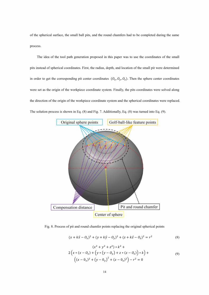
The idea of the tool path generation proposed in this paper was to use the coordinates of the small
pits instead of spherical coordinates. First, the radius, depth, and location of the small pit were determined
in order to get the corresponding pit center coordinates (𝑂𝑥 , 𝑂𝑦 , 𝑂𝑧). Then the sphere center coordinates
were set as the origin of the workpiece coordinate system. Finally, the pits coordinates were solved along
the direction of the origin of the workpiece coordinate system and the spherical coordinates were replaced.
The solution process is shown in Eq. (8) and Fig. 7. Additionally, Eq. (8) was turned into Eq. (9).
Fig. 8. Process of pit and round chamfer points replacing the original spherical points
(𝑥 + 𝑘�⃑� − 𝑂𝑥)2 + (𝑦 + 𝑘�⃑� − 𝑂𝑦)2 + (𝑧 + 𝑘𝑧 − 𝑂𝑧)2 = 𝑟2 (8) (𝑥2 + 𝑦2 + 𝑧2) ∗ 𝑘2 +2(𝑥 ∗ (𝑥 − 𝑂𝑥) + (𝑦 ∗ (𝑦 − 𝑂𝑦) + 𝑧 ∗ (𝑧 − 𝑂𝑧)) ∗ 𝑘) +((𝑥 − 0𝑥)2 + (𝑦 − 0𝑦)2 + (𝑧 − 0𝑧)2) − 𝑟2 = 0 (9)
15
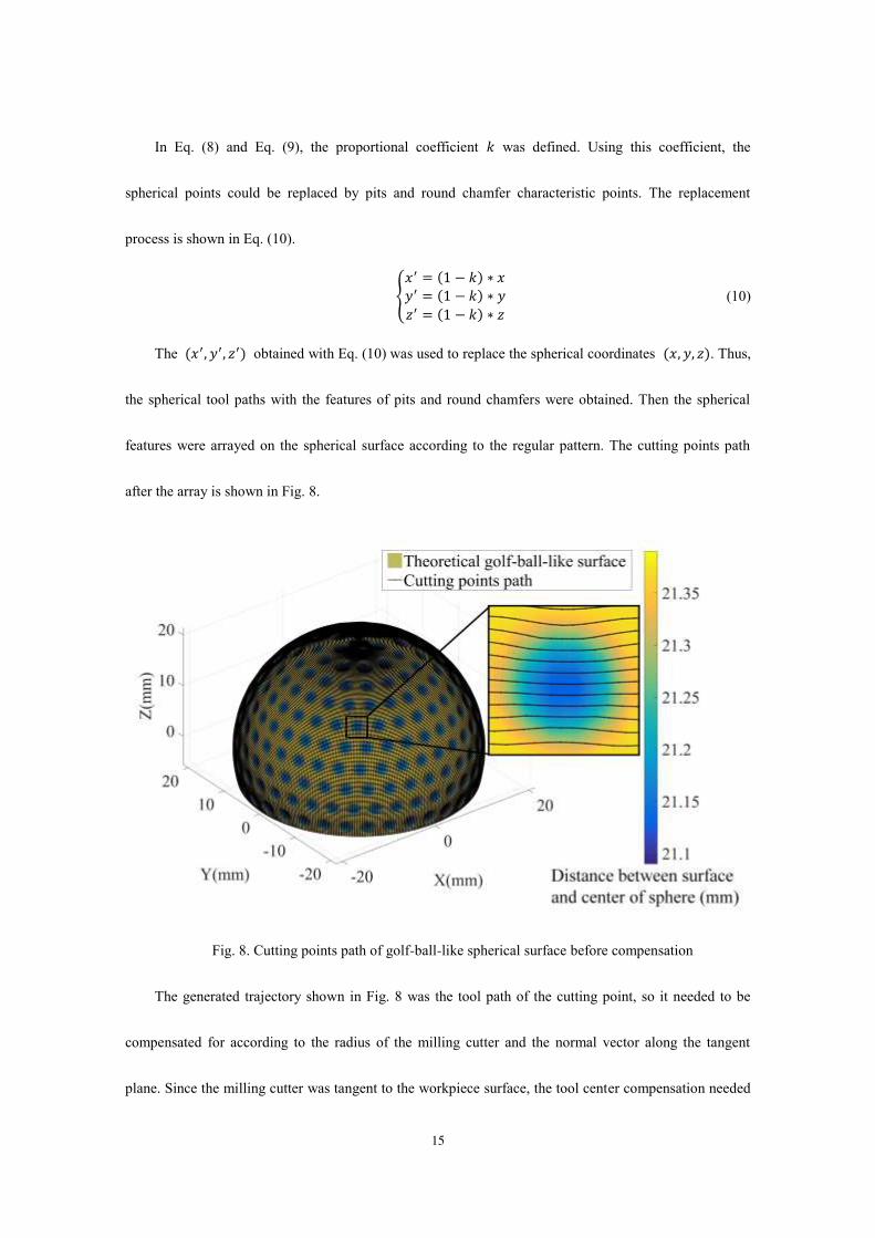
In Eq. (8) and Eq. (9), the proportional coefficient 𝑘 was defined. Using this coefficient, the
spherical points could be replaced by pits and round chamfer characteristic points. The replacement
process is shown in Eq. (10).
{𝑥′ = (1 − 𝑘) ∗ 𝑥𝑦′ = (1 − 𝑘) ∗ 𝑦𝑧′ = (1 − 𝑘) ∗ 𝑧 (10)
The (𝑥′, 𝑦′, 𝑧′) obtained with Eq. (10) was used to replace the spherical coordinates (𝑥, 𝑦, 𝑧). Thus,
the spherical tool paths with the features of pits and round chamfers were obtained. Then the spherical
features were arrayed on the spherical surface according to the regular pattern. The cutting points path
after the array is shown in Fig. 8.
Fig. 8. Cutting points path of golf-ball-like spherical surface before compensation
The generated trajectory shown in Fig. 8 was the tool path of the cutting point, so it needed to be
compensated for according to the radius of the milling cutter and the normal vector along the tangent
plane. Since the milling cutter was tangent to the workpiece surface, the tool center compensation needed

16
to be compensated for in three parts, as shown in Fig. 9.
Fig. 9. Milling cutter radius compensation
According to Eq. (11), the radius of the milling cutter was compensated for:
{ 𝑥′′ = 𝑥′ ± 𝑑𝑟(x'-O𝑥)/√(x'-O𝑥)2 + (𝑦′-O𝑦)2 + (𝑧′-O𝑧)2𝑦′′ = 𝑦′ ± 𝑑𝑟(y'-O𝑦)/√(x'-O𝑥)2 + (𝑦′-O𝑦)2 + (𝑧′-O𝑧)2𝑧′′ = 𝑧′ ± 𝑑𝑟(z'-O𝑥)/√(x'-O𝑥)2 + (𝑦′-O𝑦)2 + (𝑧′-O𝑧)2
(11)
In Eq. (11), 𝑥′, 𝑦′, 𝑧′ are the coordinates of the contact point between the milling cutter and the
workpiece surface. 𝑥′′, 𝑦′′, 𝑧′′ are the milling cutter center coordinates after the compensation. 𝑑𝑟 is the
milling cutter radius. 𝑂𝑥 , 𝑂𝑦 , 𝑂𝑧 are the sphere center coordinates of the workpiece. After the
golf-ball-like spherical tool path compensated for the radius of the milling cutter, the center of the milling
cutter path was as shown in Fig. 10.

17
Fig. 10. Tool center path of golf-ball-like spherical surface after compensation
{ 𝐵 = 𝑎𝑟𝑐𝑐𝑜𝑠 ( 𝑧′′√𝑥′′2+𝑦′′2) + 𝐵′𝐶 = 𝑎𝑟𝑐𝑡𝑎𝑛 (𝑥′′/𝑦′′) (12)
In Eq. (12), 𝑥′′, 𝑦′′, 𝑧′′ are the central coordinates of the milling cutter after the compensation, 𝐵′ is the rake angle of the B direction, and 𝐵, 𝐶 represents the coordinates of the B axis and the C axis.
Through the RTCP function of the machine tool, the tool center path was converted from the
machine coordinate system to the workpiece coordinate system. Fig. 11 shows the change of the tool axis
swing form before and after the compensation.
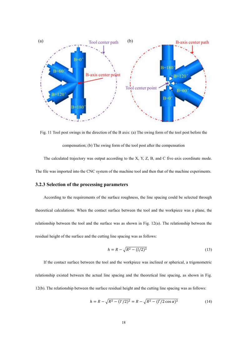
18
Fig. 11 Tool post swings in the direction of the B axis: (a) The swing form of the tool post before the
compensation; (b) The swing form of the tool post after the compensation
The calculated trajectory was output according to the X, Y, Z, B, and C five-axis coordinate mode.
The file was imported into the CNC system of the machine tool and then that of the machine experiments.
3.2.3 Selection of the processing parameters
According to the requirements of the surface roughness, the line spacing could be selected through
theoretical calculations. When the contact surface between the tool and the workpiece was a plane, the
relationship between the tool and the surface was as shown in Fig. 12(a). The relationship between the
residual height of the surface and the cutting line spacing was as follows:
ℎ = 𝑅 − √𝑅2 − (𝑙/2)2 (13)
If the contact surface between the tool and the workpiece was inclined or spherical, a trigonometric
relationship existed between the actual line spacing and the theoretical line spacing, as shown in Fig.
12(b). The relationship between the surface residual height and the cutting line spacing was as follows:
ℎ = 𝑅 − √𝑅2 − (𝑙′/2)2 = 𝑅 − √𝑅2 − (𝑙′/2 cos 𝛼)2 (14)

19
Because the cutting line spacing was quite small, Fig. 12(b) could be approximately equivalent to the
calculation of Fig. 12(a). The requirement of the surface roughness was 100 nm. This meant that the root
mean square of all of the z parameters in a sampling area was less than 0.1 μm. Considering the
influences of the cutting heat, cutting force, material properties, cutting environment, and other conditions
during the machining process, the theoretical ascending distance had to be less than 30 μm to satisfy the
surface quality requirements.
Fig. 12. The relationship between the contact method and the residual height: (a) The arc blade in contact
with the plane; (b) The arc blade in contact with the spherical surface
4 Experimental
4.1 Machining results
The process parameters were set according to the above requirements and the conduct verification
experiments on the edited tool path. First, the blank workpiece was processed by rough turning, and the
machining allowance that was reserved for turning the spherical surface was 200 μm. After turning the
spherical surface, the surface milling of the golf-ball-like spherical surface was performed. The milling
process and the corresponding parameters are shown in Table 2.
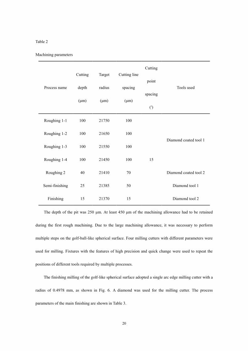
20
Table 2
Machining parameters
Process name
Cutting
depth
(μm)
Target
radius
(μm)
Cutting line
spacing
(μm)
Cutting
point
spacing
(′)
Tools used
Roughing 1-1 100 21750 100
15
Diamond coated tool 1
Roughing 1-2 100 21650 100
Roughing 1-3 100 21550 100
Roughing 1-4 100 21450 100
Roughing 2 40 21410 70 Diamond coated tool 2
Semi-finishing 25 21385 50 Diamond tool 1
Finishing 15 21370 15 Diamond tool 2
The depth of the pit was 250 μm. At least 450 μm of the machining allowance had to be retained
during the first rough machining. Due to the large machining allowance, it was necessary to perform
multiple steps on the golf-ball-like spherical surface. Four milling cutters with different parameters were
used for milling. Fixtures with the features of high precision and quick change were used to repeat the
positions of different tools required by multiple processes.
The finishing milling of the golf-like spherical surface adopted a single arc edge milling cutter with a
radius of 0.4978 mm, as shown in Fig. 6. A diamond was used for the milling cutter. The process
parameters of the main finishing are shown in Table 3.

21
Table 3
Finishing process parameters
Process
parameters
Spindle speed
(r/min)
Cutting line
spacing (μm)
Cutting depth
(μm)
Feed rate
(r/min)
Tool
inclination (°)
Parameter 10295 15 15 2 15
The finished part of the machining experiment is shown in Fig. 13. It can be seen from the figure that
the processed sample had the characteristics of a golf-like spherical surface, spherical pits, and round
chamfers. The features on the sphere were distributed according to the specified laws in the program.
Thus, the workpiece shown in Fig. 13 could satisfy the expected requirements and it could prove the
feasibility of the tool path method.
Fig 13. Ultra-precision five-axis milling golf-like spherical workpiece
4.2 Analysis and discussion
In order to study the surface condition of the processed sample, a Leitz PMM-Ultra three-coordinate
measuring machine was used to scan the spherical surface. The maximum allowable error of the machine
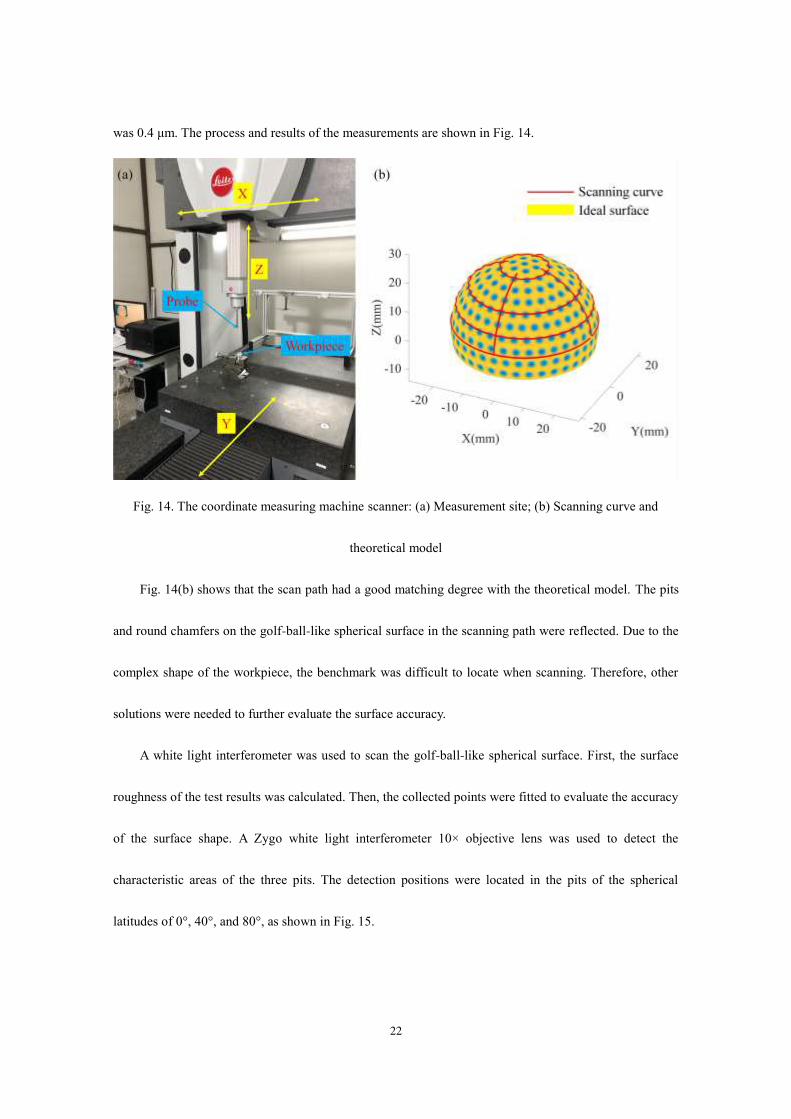
22
was 0.4 μm. The process and results of the measurements are shown in Fig. 14.
Fig. 14. The coordinate measuring machine scanner: (a) Measurement site; (b) Scanning curve and
theoretical model
Fig. 14(b) shows that the scan path had a good matching degree with the theoretical model. The pits
and round chamfers on the golf-ball-like spherical surface in the scanning path were reflected. Due to the
complex shape of the workpiece, the benchmark was difficult to locate when scanning. Therefore, other
solutions were needed to further evaluate the surface accuracy.
A white light interferometer was used to scan the golf-ball-like spherical surface. First, the surface
roughness of the test results was calculated. Then, the collected points were fitted to evaluate the accuracy
of the surface shape. A Zygo white light interferometer 10× objective lens was used to detect the
characteristic areas of the three pits. The detection positions were located in the pits of the spherical
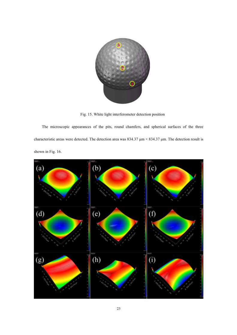
latitudes of 0°, 40°, and 80°, as shown in Fig. 15.
23
Fig. 15. White light interferometer detection position
The microscopic appearances of the pits, round chamfers, and spherical surfaces of the three
characteristic areas were detected. The detection area was 834.37 μm × 834.37 μm. The detection result is
shown in Fig. 16.
24
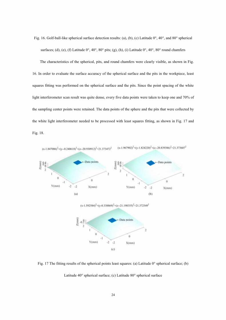
Fig. 16. Golf-ball-like spherical surface detection results: (a), (b), (c) Latitude 0°, 40°, and 80° spherical
surfaces; (d), (e), (f) Latitude 0°, 40°, 80° pits; (g), (h), (i) Latitude 0°, 40°, 80° round chamfers
The characteristics of the spherical, pits, and round chamfers were clearly visible, as shown in Fig.
16. In order to evaluate the surface accuracy of the spherical surface and the pits in the workpiece, least
squares fitting was performed on the spherical surface and the pits. Since the point spacing of the white
light interferometer scan result was quite dense, every five data points were taken to keep one and 70% of
the sampling center points were retained. The data points of the sphere and the pits that were collected by
the white light interferometer needed to be processed with least squares fitting, as shown in Fig. 17 and
Fig. 18.
Fig. 17 The fitting results of the spherical points least squares: (a) Latitude 0° spherical surface; (b)
Latitude 40° spherical surface; (c) Latitude 80° spherical surface

25
Fig. 18. The fitting results of the pit points least squares (mm): (a) Latitude 0° pits; (b) Latitude 40° pits;
(c) Latitude 80° pits
The surface fitting formula is shown on the front of each figure. The number on the right side of the
equal sign in each figure is the fitted radius. According to the fitting results of the spherical surface and
the pits, the fitting radius was within 5 μm of the ideal radius. Combined with the machine parameters in
Table 1, the fitted results met the expected requirements.
Furthermore, it was necessary to evaluate the micro morphology of the workpiece. The cross-section
needed to be analyzed in order to prove the relationship between the surface residual height and the
cutting line spacing shown in Fig. 12. The results shown in Fig. 16 (a) were examples to be analyzed. The
comparison between the cross-section height and the theoretical value is shown in Fig. 19.
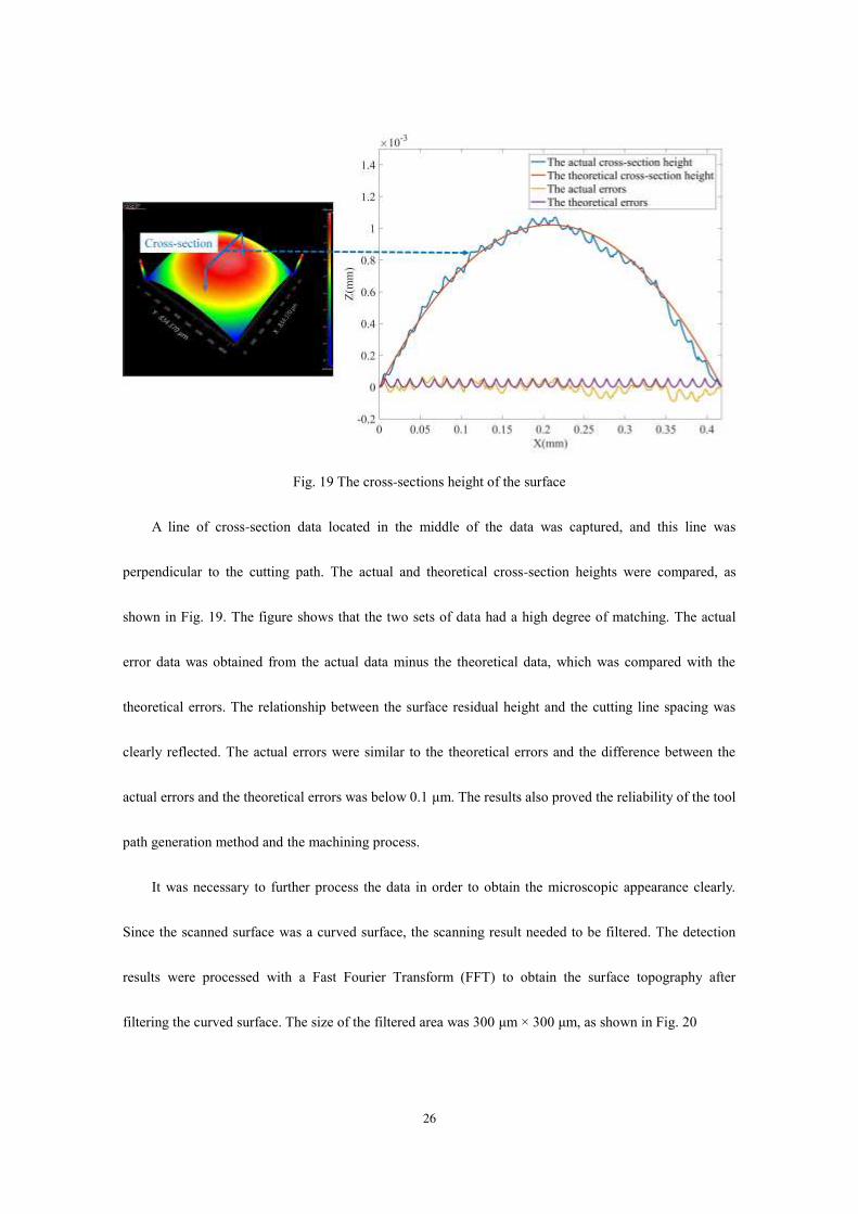
26
Fig. 19 The cross-sections height of the surface
A line of cross-section data located in the middle of the data was captured, and this line was
perpendicular to the cutting path. The actual and theoretical cross-section heights were compared, as
shown in Fig. 19. The figure shows that the two sets of data had a high degree of matching. The actual
error data was obtained from the actual data minus the theoretical data, which was compared with the
theoretical errors. The relationship between the surface residual height and the cutting line spacing was
clearly reflected. The actual errors were similar to the theoretical errors and the difference between the
actual errors and the theoretical errors was below 0.1 μm. The results also proved the reliability of the tool
path generation method and the machining process.
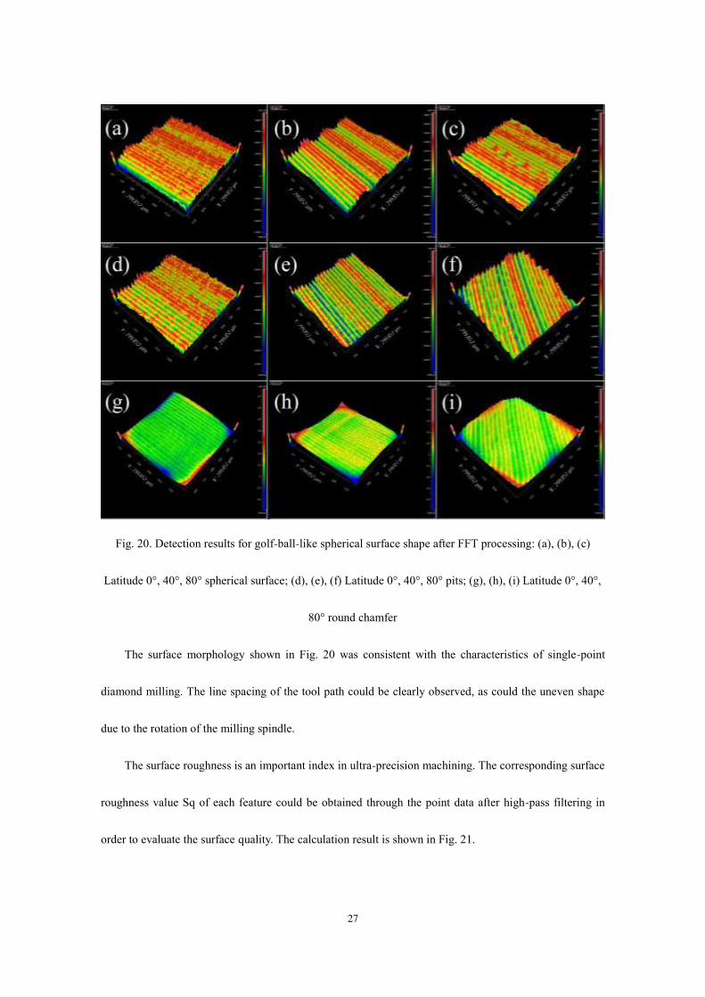
It was necessary to further process the data in order to obtain the microscopic appearance clearly.
Since the scanned surface was a curved surface, the scanning result needed to be filtered. The detection
results were processed with a Fast Fourier Transform (FFT) to obtain the surface topography after
filtering the curved surface. The size of the filtered area was 300 μm × 300 μm, as shown in Fig. 20
27
Fig. 20. Detection results for golf-ball-like spherical surface shape after FFT processing: (a), (b), (c)
Latitude 0°, 40°, 80° spherical surface; (d), (e), (f) Latitude 0°, 40°, 80° pits; (g), (h), (i) Latitude 0°, 40°,
80° round chamfer
The surface morphology shown in Fig. 20 was consistent with the characteristics of single-point
diamond milling. The line spacing of the tool path could be clearly observed, as could the uneven shape
due to the rotation of the milling spindle.
The surface roughness is an important index in ultra-precision machining. The corresponding surface
roughness value Sq of each feature could be obtained through the point data after high-pass filtering in
order to evaluate the surface quality. The calculation result is shown in Fig. 21.
28
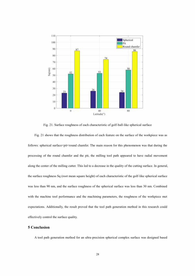
Fig. 21. Surface roughness of each characteristic of golf-ball-like spherical surface
Fig. 21 shows that the roughness distribution of each feature on the surface of the workpiece was as
follows: spherical surface<pit<round chamfer. The main reason for this phenomenon was that during the
processing of the round chamfer and the pit, the milling tool path appeared to have radial movement
along the center of the milling cutter. This led to a decrease in the quality of the cutting surface. In general,
the surface roughness Sq (root mean square height) of each characteristic of the golf-like spherical surface
was less than 90 nm, and the surface roughness of the spherical surface was less than 30 nm. Combined
with the machine tool performance and the machining parameters, the roughness of the workpiece met
expectations. Additionally, the result proved that the tool path generation method in this research could
effectively control the surface quality.
5 Conclusion
A tool path generation method for an ultra-precision spherical complex surface was designed based

29
on the ultra-precision five-axis machine tool, and a representative golf-ball-like spherical workpiece was
employed as the machining object for the verification of the proposed method. Through the
ultra-precision five-axis turning and milling, a golf-ball-like spherical surface was achieved. Finally, the
surface accuracy and the surface quality of the workpiece were inspected and analyzed. The conclusions
were drawn as follows:
(1) An effective method for generating tool paths for ultra-precision spherical complex surface machining
was proposed. The tool path generating method could effectively achieve the processing of pits and round
chamfers of spherical complex surfaces. Furthermore, this method could also solve the problem of tool
radius compensation.
(2) Based on the ultra-precision five-axis machine tool and the generated tool paths, a complete set of
golf-ball-like spherical machining plans was formulated. After the machining, the workpiece was
characterized with a three-coordinate measuring machine and a white light interferometer. The
measurement results showed that the machining results had a high matching accuracy with the theoretical
model. The error between the least square fitting and the theoretical value was less than 5 μm. The
reliability of the tool path generation method was verified.
(3) The feasibility of the tool path generating method was verified through processing experiments and
the inspection of the processed parts. Compared with conventional commercial software, the designed
toolpath generation method could effectively meet the requirements of ultra-precision machining when
calculating tool paths.
Funding This work was supported by the Science Challenge Project of China (Grant No.
TZ2018006-0202-01)

30
Compliance with ethical standards
Conflict of interest The authors declare that they have no conflicts of interest.
References
[1] Yuan JL, Lyu BH, Hang W, Deng QF (2017) Review on the progress of ultra-precision machining
technologies. Front Mech Eng 12 (2):158-180. doi:10.1007/s11465-017-0455-9
[2] Kong LB, Cheung CF (2012) Prediction of surface generation in ultra-precision raster milling of
optical freeform surfaces using an Integrated Kinematics Error Model. Adv Eng Softw 45 (1):124-136.
doi:10.1016/j.advengsoft.2011.09.011
[3] Cheung CF, Li HF, Lee WB, To S, Kong LB (2007) An integrated form characterization method for
measuring ultra-precision freeform surfaces. Int J Mach Tools Manuf 47 (1):81-91.
doi:10.1016/j.ijmachtools.2006.02.013
[4] Takino H, Kawai T, Takeuchi Y (2007) 5-axis control ultra-precision machining of complex-shaped
mirrors for extreme ultraviolet lithography system. CIRP Ann-Manuf Technol 56 (1):123-126.
doi:10.1016/j.cirp.2007.05.031
[5] Tauhiduzzaman M, Veldhuis SC (2014) Effect of material microstructure and tool geometry on surface
generation in single point diamond turning. Precis Eng-J Int Soc Precis Eng Nanotechnol 38 (3):481-491.
doi:10.1016/j.precisioneng.2014.01.002
[6] Zhang SJ, Zhou YP, Zhang HJ, Xiong ZW, To S (2019) Advances in ultra-precision machining of
micro-structured functional surfaces and their typical applications. Int J Mach Tools Manuf 142:16-41.
doi:10.1016/j.ijmachtools.2019.04.009
[7] Tie GP, Dai YF, Guan CL, Zhu DC, Song B (2013) Research on full-aperture ductile cutting of KDP

31
crystals using spiral turning technique. J Mater Process Technol 213 (12):2137-2144.
doi:10.1016/j.jmatprotec.2013.06.006
[8] Li CJ, Li Y, Gao X, Duong CV (2015) Ultra-precision machining of Fresnel lens mould by
single-point diamond turning based on axis B rotation. Int J Adv Manuf Technol 77 (5-8):907-913.
doi:10.1007/s00170-014-6522-z
[9] Sze-Wei G, Han-Seok L, Rahman M, Watt F (2007) A fine tool servo system for global position error
compensation for a miniature ultra-precision lathe. Int J Mach Tools Manuf 47 (7-8):1302-1310.
doi:10.1016/j.ijmachtools.2006.08.023
[10] Yu DP, Gan SW, Wong YS, Hong GS, Rahman M, Yao J (2012) Optimized tool path generation for
fast tool servo diamond turning of micro-structured surfaces. Int J Adv Manuf Technol 63
(9-12):1137-1152. doi:10.1007/s00170-012-3964-z
[11] Yuan YJ, Zhang DW, Jing XB, Zhu HY, Zhou WL, Cao J, Ehmann KF (2019) Fabrication of
hierarchical freeform surfaces by 2D compliant vibration-assisted cutting. Int J Mech Sci 152:454-464.
doi:10.1016/j.ijmecsci.2018.12.051
[12] Mishra V, Burada DR, Pant KK, Karar V, Jha S, Khan GS (2019) Form error compensation in the
slow tool servo machining of freeform optics. Int J Adv Manuf Technol 105 (1-4):1623-1635.
doi:10.1007/s00170-019-04359-w
[13] Kong LB, Cheung CF, Lee WB (2016) A theoretical and experimental investigation of orthogonal
slow tool servo machining of wavy microstructured patterns on precision rollers. Precis Eng-J Int Soc
Precis Eng Nanotechnol 43:315-327. doi:10.1016/j.precisioneng.2015.08.012
[14] Deng WJ, Yin XL, Tang W, Xue DL, Zhang XJ (2019) Research on Ion Beam Figuring System with

32
Five-Axis Hybrid Mechanism for Complex Optical Surface. In: Li X, Plummer WT, Fan B, Pu M, Wan Y,
Luo X (eds) 9th International Symposium on Advanced Optical Manufacturing and Testing Technologies:
Advanced Optical Manufacturing Technologies, vol 10838. Proceedings of SPIE. Spie-Int Soc Optical
Engineering, Bellingham. doi:10.1117/12.2504957
[15] Butt MA, Yang YQ, Pei XZ, Liu Q (2018) Five-axis milling vibration attenuation of freeform
thin-walled part by eddy current damping. Precis Eng-J Int Soc Precis Eng Nanotechnol 51:682-690.
doi:10.1016/j.precisioneng.2017.11.010
[16] Luo M, Luo H, Zhang DH, Tang K (2018) Improving tool life in multi-axis milling of Ni-based
superalloy with ball-end cutter based on the active cutting edge shift strategy. J Mater Process Technol
252:105-115. doi:10.1016/j.jmatprotec.2017.09.010
[17] Xu JT, Zhang DY, Sun YW (2019) Kinematics performance oriented smoothing method to plan tool
orientations for 5-axis ball-end CNC machining. Int J Mech Sci 157:293-303.
doi:10.1016/j.ijmecsci.2019.04.038
[18] Cheng Q, Feng QA, Liu ZF, Gu PH, Cai LG (2015) Fluctuation prediction of machining accuracy for
multi-axis machine tool based on stochastic process theory. Proc Inst Mech Eng Part C-J Eng Mech Eng
Sci 229 (14):2534-2550. doi:10.1177/0954406214562633
[19] Wang HW, Ran Y, Zhang SY, Li YL (2020) Coupling and Decoupling Measurement Method of
Complete Geometric Errors for Multi-Axis Machine Tools. Appl Sci-Basel 10 (6):19.
doi:10.3390/app10062164
[20] McCall B, Tkaczyk TS (2013) Rapid fabrication of miniature lens arrays by four-axis single point
diamond machining. Opt Express 21 (3):3557-3572. doi:10.1364/oe.21.003557

33
[21] Dutterer BS, Lineberger JL, Smilie PJ, Hildebrand DS, Harriman TA, Davies MA, Suleski TJ, Lucca
DA (2014) Diamond milling of an Alvarez lens in germanium. Precis Eng-J Int Soc Precis Eng
Nanotechnol 38 (2):398-408. doi:10.1016/j.precisioneng.2013.12.006
[22] Yuan YJ, Zhang DW, Jing XB, Ehmann KF (2020) Freeform surface fabrication on hardened steel by
double frequency vibration cutting. J Mater Process Technol 275:9. doi:10.1016/j.jmatprotec.2019.116369
[23] Kong LB, Ma YG, Ren MJ, Xu M, Cheung CA (2020) Generation and characterization of
ultra-precision compound freeform surfaces. Sci Prog 103 (1):21. doi:10.1177/0036850419880112
[24] Koyama Y, Nakamoto K, Takeuchi Y (2012) Development of CAPP/CAM System for Ultraprecision
Micromachining -Process Planning Considering Setting Error. In: Lee WB, Cheung CF, To S (eds)
Proceedings of Precision Engineering and Nanotechnology, vol 516. Key Engineering Materials. Trans
Tech Publications Ltd, Stafa-Zurich, pp 66-72. doi:10.4028/www.scientific.net/KEM.516.66
[25] Chen MJ, Guo WX, Li D (2004) Research of the complex surface algorithm based on recursive
subdivision numeric control interpolation. In: Ai X, Li J, Huang C (eds) Advances in Materials
Manufacturing Science and Technology, vol 471-472. Materials Science Forum. Trans Tech Publications
Ltd, Durnten-Zurich, pp 155-161. doi:10.4028/www.scientific.net/MSF.471-472.155
[26] Chen MJ, Xiao Y, Tian WL, Wu CY, Chu X (2014) Theoretical and Experimental Research on Error
Analysis and Optimization of Tool Path in Fabricating Aspheric Compound Eyes by Precision Micro
Milling. Chin J Mech Eng 27 (3):558-566. doi:10.3901/cjme.2014.03.558
[27] Huang R, Zhang XQ, Rahman M, Kumar AS, Liu K (2015) Ultra-precision machining of radial
Fresnel lens on roller moulds. CIRP Ann-Manuf Technol 64 (1):121-124. doi:10.1016/j.cirp.2015.04.062
[28] Chen CCA, Chen CM, Chen JR (2007) Toolpath generation for diamond shaping of aspheric lens

34
array. J Mater Process Technol 192:194-199. doi:10.1016/j.jmatprotec.2007.04.024
[29] Gao D, To S, Lee WB (2006) Tool path generation for machining of optical freeform surfaces by an
ultra-precision multiaxis machine tool. Proc Inst Mech Eng Part B-J Eng Manuf 220 (12):2021-2026.
doi:10.1243/09544054jem614
[30] Brecher C, Lange S, Merz M, Niehaus F, Wenzel C, Winterschladen M (2006) NURBS based
ultra-precision free-form machining. CIRP Ann-Manuf Technol 55 (1):547-550.
doi:10.1016/s0007-8506(07)60479-x
[31] Arivazhagan A (2020) Toolpath algorithm for free form irregular contoured walls / surfaces with
internal deflecting connections. Mater Today-Proc 22:3037-3047
[32] Wu BH, Liang MC, Zhang Y, Luo M, Tang K (2018) Optimization of machining strip width using
effective cutting shape of flat-end cutter for five-axis free-form surface machining. Int J Adv Manuf
Technol 94 (5-8):2623-2633. doi:10.1007/s00170-017-0953-2
[33] Moodleah S, Bohez EJ, Makhanov SS (2016) Five-axis machining of STL surfaces by adaptive
curvilinear toolpaths. Int J Prod Res 54 (24):7296-7329. doi:10.1080/00207543.2016.1176265
[34] Ding S, Mannan MA, Poo AN, Yang DCH, Han Z (2005) The implementation of adaptive isoplanar
tool path generation for the machining of free-form surfaces. Int J Adv Manuf Technol 26 (7-8):852-860.
doi:10.1007/s00170-004-2058-y
[35] Lin ZW, Fu JZ, Shen HY, Gan WF (2014) An accurate surface error optimization for five-axis
machining of freeform surfaces. Int J Adv Manuf Technol 71 (5-8):1175-1185.
doi:10.1007/s00170-013-5549-x
[36] Lock GD, Edwards S, Almond DP (2010) Flow visualization experiments demonstrating the reverse

35
swing of a cricket ball. Proc Inst Mech Eng Part P-J Sport Eng Technol 224 (P3):191-199.
doi:10.1243/17543371jset73
[37] Scobie JA, Sangan CM, Lock GD (2014) Flow visualisation experiments on sports balls. In: James D,
Choppin S, Allen T, Wheat J, Fleming P (eds) Engineering of Sport 10, vol 72. Procedia Engineering.
Elsevier Science Bv, Amsterdam, pp 738-743. doi:10.1016/j.proeng.2014.06.125
[38] Cripps RJ, Cross B, Hunt M, Mullineux G (2017) Singularities in five-axis machining: Cause, effect
and avoidance. Int J Mach Tools Manuf 116:40-51. doi:10.1016/j.ijmachtools.2016.12.002
[39] Jiang Z, Ding JX, Zhang J, Ding QC, Li QZ, Du L, Wang W (2019) Research on detection of the
linkage performance for five-axis CNC machine tools based on RTCP trajectories combination. Int J Adv
Manuf Technol 100 (1-4):941-962. doi:10.1007/s00170-018-2715-1
Figures
Figure 1
The golf-ball-like spherical surface: (a) The three-dimensional diagram, (b) The engineering drawing
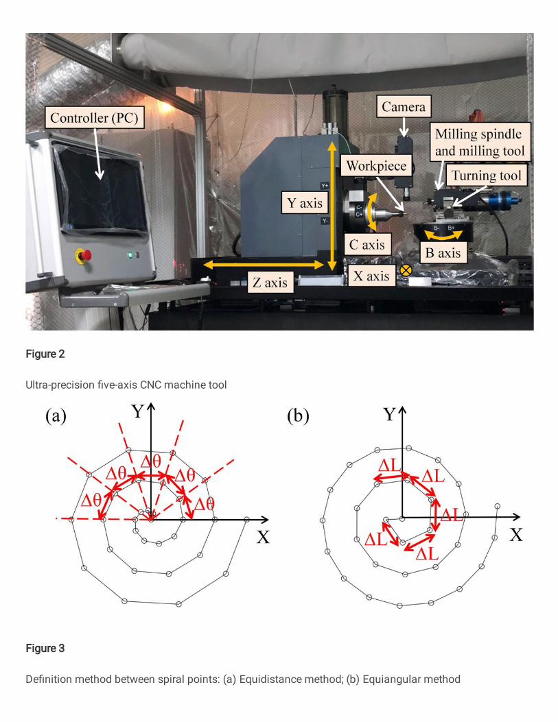
Figure 2
Ultra-precision �ve-axis CNC machine tool
Figure 3
De�nition method between spiral points: (a) Equidistance method; (b) Equiangular method

Figure 4
Tool radius compensation method

Figure 5
Tool center path diagram
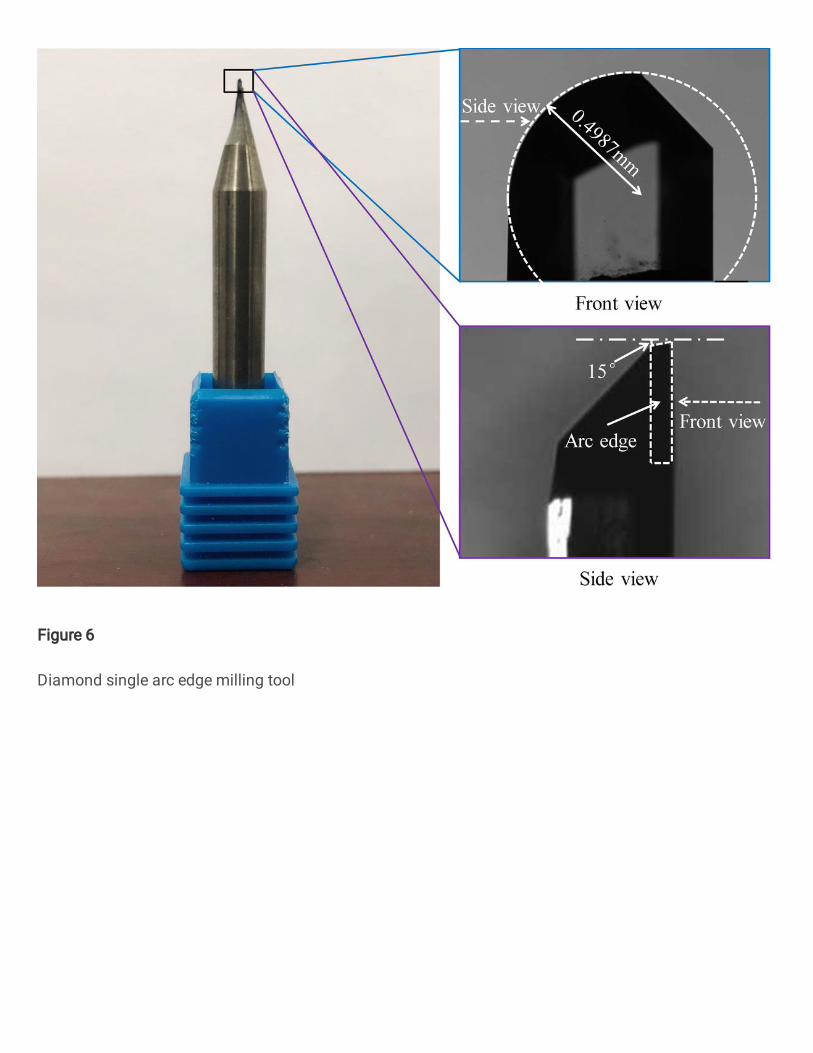
Figure 6
Diamond single arc edge milling tool
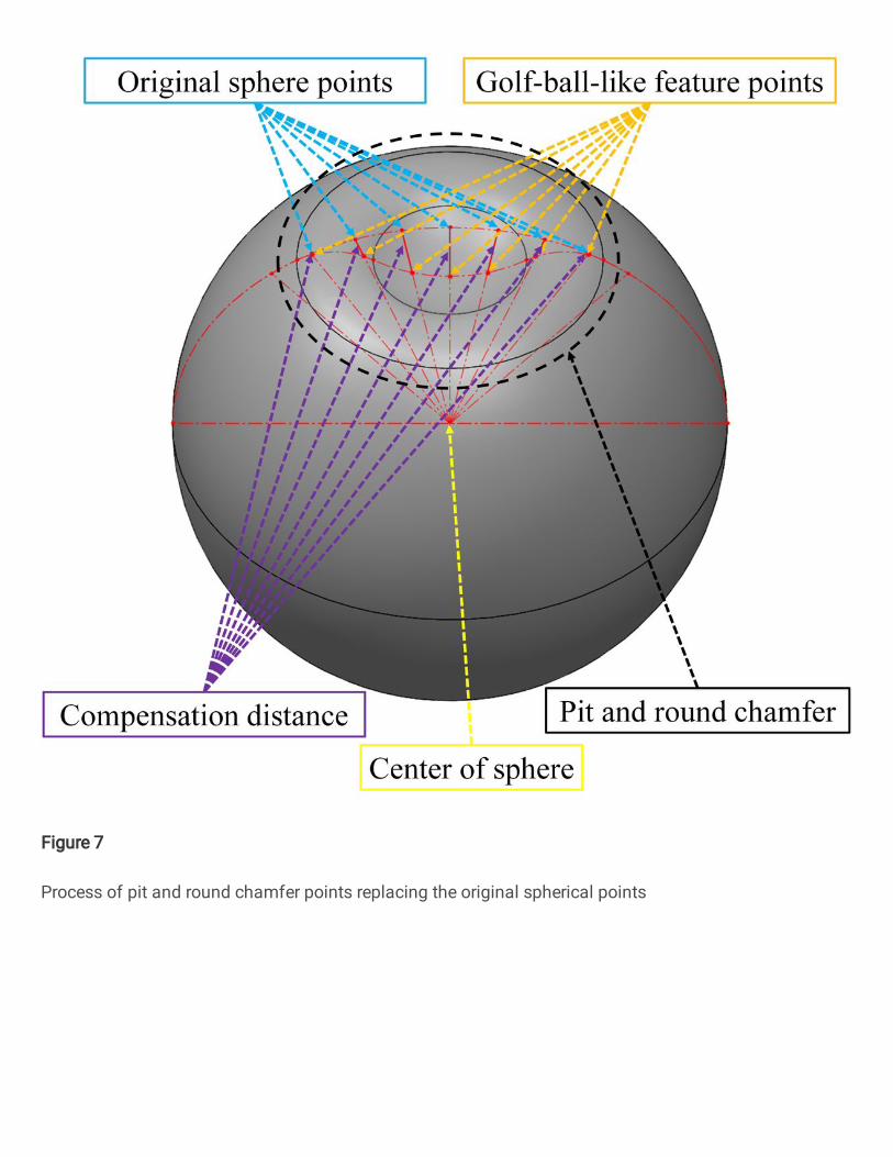
Figure 7
Process of pit and round chamfer points replacing the original spherical points
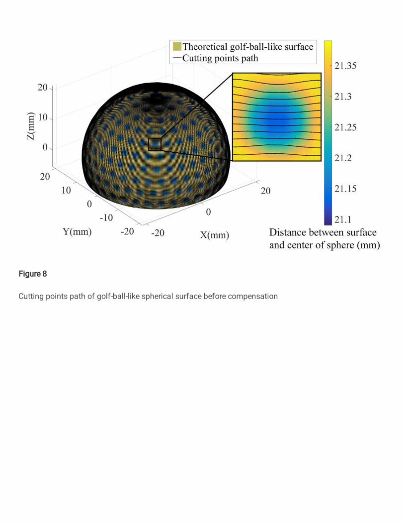
Figure 8
Cutting points path of golf-ball-like spherical surface before compensation

Figure 9
Milling cutter radius compensation

Figure 10
Tool center path of golf-ball-like spherical surface after compensation

Figure 11
Tool post swings in the direction of the B axis: (a) The swing form of the tool post before thecompensation; (b) The swing form of the tool post after the compensation
Figure 12
The relationship between the contact method and the residual height: (a) The arc blade in contact withthe plane; (b) The arc blade in contact with the spherical surface

Figure 13
Ultra-precision �ve-axis milling golf-like spherical workpiece

Figure 14
The coordinate measuring machine scanner: (a) Measurement site; (b) Scanning curve and theoreticalmodel

Figure 15
White light interferometer detection position

Figure 16
Golf-ball-like spherical surface detection results: (a), (b), (c) Latitude 0°, 40°, and 80° spherical surfaces;(d), (e), (f) Latitude 0°, 40°, 80° pits; (g), (h), (i) Latitude 0°, 40°, 80° round chamfers

Figure 17
The �tting results of the spherical points least squares: (a) Latitude 0° spherical surface; (b) Latitude 40°spherical surface; (c) Latitude 80° spherical surface

Figure 18
The �tting results of the pit points least squares (mm): (a) Latitude 0° pits; (b) Latitude 40° pits; (c)Latitude 80° pits
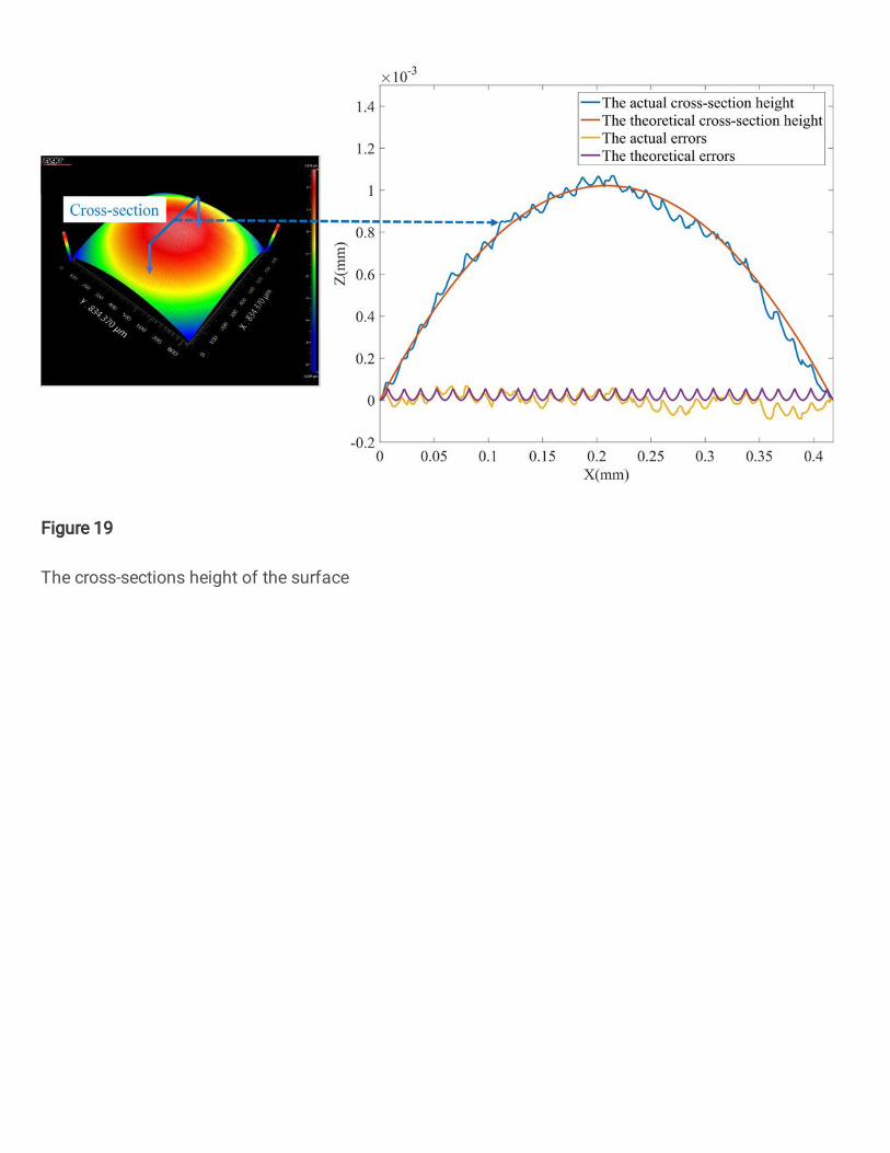
Figure 19
The cross-sections height of the surface
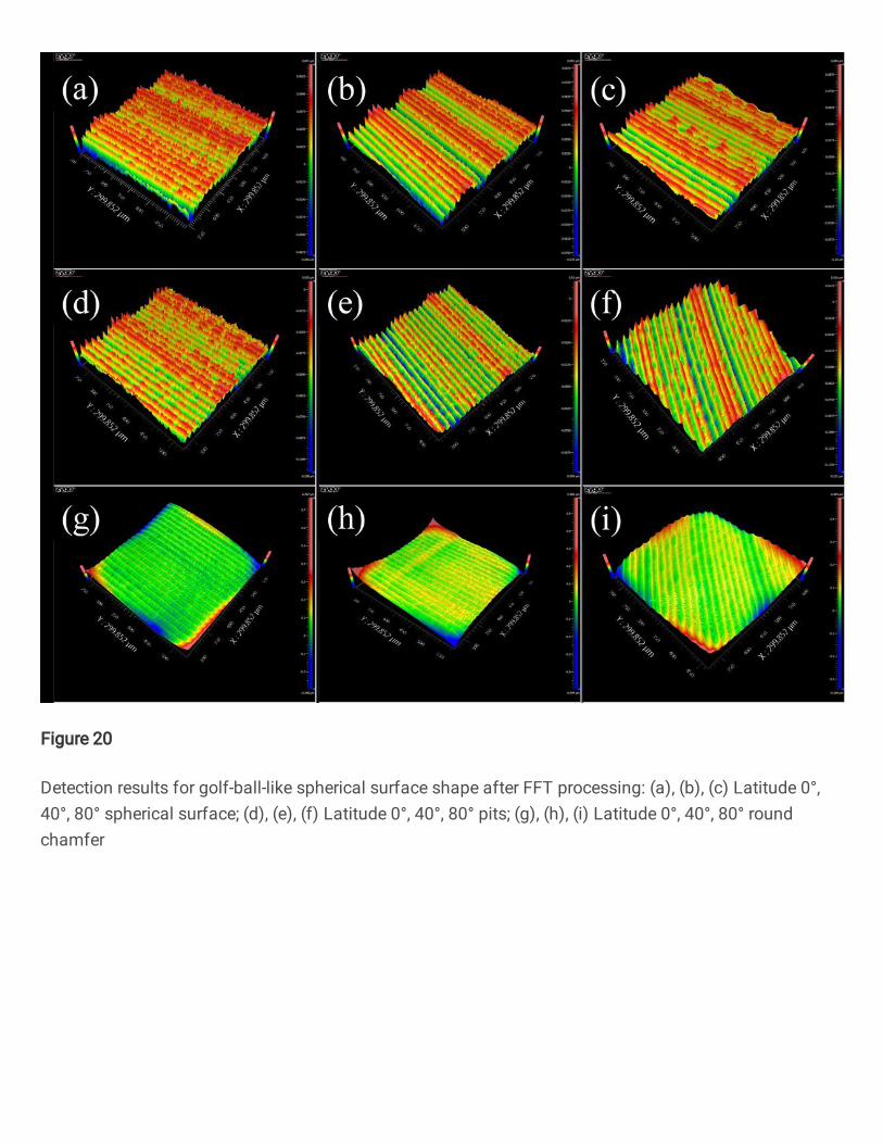
Figure 20
Detection results for golf-ball-like spherical surface shape after FFT processing: (a), (b), (c) Latitude 0°,40°, 80° spherical surface; (d), (e), (f) Latitude 0°, 40°, 80° pits; (g), (h), (i) Latitude 0°, 40°, 80° roundchamfer
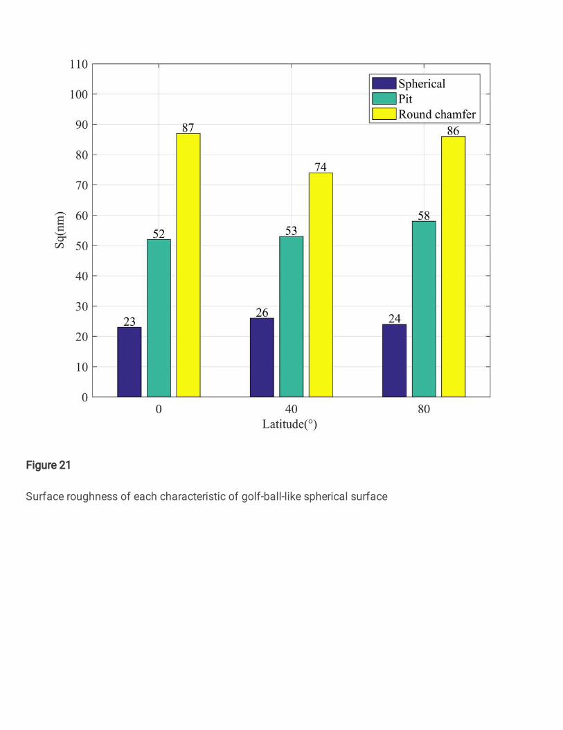
Figure 21
Surface roughness of each characteristic of golf-ball-like spherical surface