study of the underfill effect on the thermal fatigue life
TRANSCRIPT
Copyright © 2009 Tech Science Press CMES, vol.40, no.1, pp.83-103, 2009
Study of the Underfill Effect on the Thermal Fatigue Lifeof WLCSP-Experiments and Finite Element Simulations
Shaw-Jyh Shin1, Chen-Hung Huang2 and Y.C. Shiah3
Abstract: Owing to the CTE (Coefficient of Thermal Expansion) mismatch amongsolder joints, IC (Integrated Circuit) chip, and PCB (Printed Circuit Board), elec-tronic packages shall experience fatigue failure after going though a period of ther-mal cycling. As a major means to enhance the reliability of the solder joints, un-derfill is often dispensed to fill the gap between the die and the substrate. Thisstudy aims at investigating how the underfill may affect the thermal fatigue lifeof WLCSP (Wafer Level Chip Scale Package) by means of FEA (finite elementanalysis). In this study, the thermal fatigue life of the WLCSP was simulated us-ing full-model. For comparison with the FEA simulations, experiments were alsoconducted for a few WLCSP with/without underfill.
Keywords: Thermal fatigue life of WLCSP, underfill, finite element analysis.
1 Introduction
Recently, 3C (computer, communication, and consumer electronics) products onthe market tend to be portable and light-weight, yet has increased functionalityto cater for consumers’ fashion. These demands have driven the IC packagingmove from Pin Through Hole to Surface Mount Technology. Instead of assem-bling the package of each individual unit after wafer dicing, recent technology hasprogressed to Wafer Level Chip Scale Packaging (WLCSP), producing packagespractically of the same size as the die. Indeed, the WLCSP technology has laid thefoundation for true integration of wafer fab, packaging, test, and burn-in at waferlevel, for the ultimate streamlining of the manufacturing process.
The CTE (Coefficient of Thermal Expansion) is a temperature-dependent materialproperty of metals and has been analyzed by Chiang, Chou, Wu, Huang and Yew
1 Dept. of Communications Eng., Feng Chia University, R.O.C.2 Dept. of Aerospace and Systems Eng., Feng Chia University, R.O.C.3 Corresponding Author. Dept. of Aerospace and Systems Eng., Feng Chia University, R.O.C.,
Email: [email protected]
84 Copyright © 2009 Tech Science Press CMES, vol.40, no.1, pp.83-103, 2009
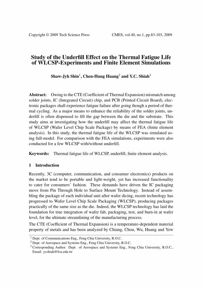
(2008), its mismatch among the solder joint, IC chip, and PCB is the main causeof the package’s failure, and significant thermal stresses shall occur on the joinedinterfaces owing to the CTE . The low melting point of solder balls makes its creepstrain behavior more likely to cause the fatigue failure than other packaging mate-rials do. Given this, the signal transmission of electronic packaging will becomeless effective, even failing at times. This problem is even more serious for WLCSP,whose solder balls are comparably small. Due to this, the reliability analysis of sol-der joints of WLCSP subjected to thermal cycling has been an important researchtopic in the electronic packaging community. As schematically shown in Fig. 1, amajor means to enhance the reliability of solder joints is to fill the gap between thedie and the substrate with underfill; however this process will increase the manu-facturing cost. Therefore, a concern may arise regarding how effective the underfillmay enhance the reliability when one is facing the cost tradeoff.
PCB
Underfill dispensing
Solder reflow
Alignment
Figure 1: No-flow underfill of WLCSP
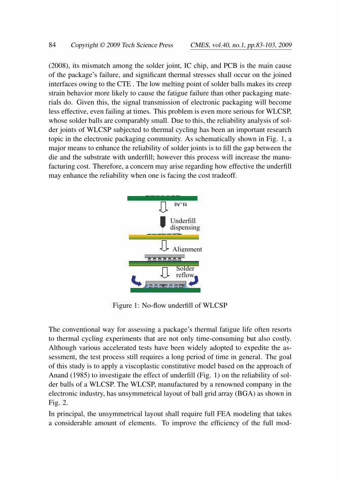
The conventional way for assessing a package’s thermal fatigue life often resortsto thermal cycling experiments that are not only time-consuming but also costly.Although various accelerated tests have been widely adopted to expedite the as-sessment, the test process still requires a long period of time in general. The goalof this study is to apply a viscoplastic constitutive model based on the approach ofAnand (1985) to investigate the effect of underfill (Fig. 1) on the reliability of sol-der balls of a WLCSP. The WLCSP, manufactured by a renowned company in theelectronic industry, has unsymmetrical layout of ball grid array (BGA) as shown inFig. 2.
In principal, the unsymmetrical layout shall require full FEA modeling that takesa considerable amount of elements. To improve the efficiency of the full mod-
Study of the Underfill Effect on the Thermal Fatigue Life 85
Figure 2: Layout of the WLCSP ball grid array
eling, we propose a sub-modeling technique that performs global analysis with acoarsely meshing scheme, subsequently following with local analysis employingrefined meshes around solder balls. This differs from the solution procedure of thecommonly used Global-Local FEA modeling. Since the BGA layout of the presentWLCSP is nearly symmetrical, we also applies the slice model and the quartermodel to analyze its thermal fatigue life as comparison of the analysis using thefull modeling.
So far, to the authors’ knowledge, pertinent studies for investigating the under-fill effect of WLCSP still remain comparably scarce in the open literature. Sun,Hochstenbach, Van Driel and Zhang (2008) experimentally analyzed the brittlefracture of intermetallic compound under high-speed pull condition. Tsai, Lai,Yeh and Chen (2008) applied the Taguchi optimization method to obtain the opti-mal design in enhancing board-level drop reliability of a WLCSP. For Chip Scalepackages, Lee, Nguyen and Selvaduray (2000) gave a review of fourteen solderjoint fatigue models with an emphasis on summarizing the features and applica-tions of each fatigue model. In recent years, a number of solder fatigue life modelshave been developed to predict the thermal fatigue life of solder joint [e.g. Man-son (1996); John, Wang, John and Wataru (1998); Amagai (1999); Cheng, Yu andChen (2005)]. These models, being categorized into stress-based, plastic-strain-based, creep-strain-based, energy-based, and damage-based methods, utilize non-elastic strain range and viscoplastic strain energy density to estimate the fatigue lifeof solder joints. For the present work, an integrated constitutive model with vis-coelastic, plastic, and creep behaviors is adopted for the solder joints to ensure theaccuracy. The analysis employs Darveaux’s approach [Darveaux (1995)], based onviscoplastic strain energy density, to predict the thermal fatigue life of solder balls.Additionally, to take into account the effects of cyclic frequency and temperatureprofile, the Engelmaier fatigue life model [Engelmaier (1983)], a modified Coffin-Manson formula based on shear strain increment, is also adopted for computation
86 Copyright © 2009 Tech Science Press CMES, vol.40, no.1, pp.83-103, 2009
of the thermal fatigue life. Sequentially, the reliability of the package is evaluatedby a two-parameter Weibull failure distribution.
To verify our predictions, WLCSP samples with daisy chain connection were exper-imented with a programmable temperature chamber, providing cyclic temperaturevariation of 00C ∼1000C until failure occurred. To monitor the failure in real-time,the electric resistance of the samples that were connected to Agilent 34970A out-side the temperature chamber was recorded by BenchLink DataLogger. The exper-iment was conducted for the both WLCSP types as comparison- one with underfilland the other without underfill.
2 Theoretical fundamentals
The fundamentals of the thermal fatigue analysis in this study include Two Param-eter Weibull Distribution [Lai, Wang, Tsai and Jen (2007)], Anand’s model [Anand(1985)], and a few methodologies for predicting the thermal fatigue life of solderballs. Before our Finite Element analysis for the WLCSP is presented, the funda-mentals are reviewed as a start.
The Weibull distribution [Weibull (1951)], a continuous probability distributionnamed after Waloddi Weibull, is often used to describe the statistical distributionof fracture in engineering reliability assessment. The Weibull distribution takes theform,
f (T ) =β
η
(T − γ
η
)β−1
e−(T−γ
η )β
= λ (T )R(T ), (1)
where T is the cyclic number, β is the shape parameter (or Weibull slope), γ isposition function, and η is scale parameter (or characteristic life). In Equation
(1), λ (T ) = β
η
(T−γ
η
)β−1is defined as the Weibull failure function and R(T ) =
e−(T−γ
η )β
is the Weibull reliability function. When γ=0, Equation (1) becomes
f2 (T ) =β
η
(Tη
)β−1
e−(Tη )β
= λ2 (T )R2 (T ) , (2)
which is referred to as the Two Parameter Weibull Distribution. More detailsregarding the Two Parameter Weibull Distribution can be referred to PrabhakarMurthy, Bulmer and Eccleston (2004).
The stress or strain-rate of viscoplastic materials exhibits a time-dependent behav-ior. For most materials, the typical plastic theory is accurate enough to describetheir material behaviors; however, some metals exhibit both creep and plastic be-haviors, especially under high temperature. The solder balls of the WLCSP, made
Study of the Underfill Effect on the Thermal Fatigue Life 87
of 63Sn/37Pb alloy, has the melting point 456◦K. For the thermal cycles with peaktemperature at 100◦C, the solder balls will undergo significant creep. According toKnecht and Fox (1991), the total strain rate includes the elastic strain rate γe, theplastic strain rate γpl , and the creep strain rate γcr, i.e.
γtot = γe + γpl + γcr, (3)
which leads to the total stress
τtot =
[1G
+Amτm
pτ
m−1
]τ +Bτ
n. (4)
In Equation (4), A, B, m are material constants. According to Anand’s model,the viscoplastic behavior should be taken into consideration when the operationaltemperature is greater than half of the melting point of the material. This kind ofbehavior appears to be similar to the creep behavior, but it is a bit more complicatedthan that. For the approach, Anand used the constitutive law for creep and an anti-deformation factor s to formulate the rate of equivalent plastic strain dεeq/dt as
dεeq
dt= A
[sinh
(ζ
σ
s
)]1/me(−
QKT ), (5)
where Q is the activation energy, m is the strain-rate sensitivity, K is the Boltzmannconstant, ζ is multiplier of stress, A is the pre-exponential factor, s is the anti-deformation factor, T is the absolute temperature, and σ is effective Cauchy stress.The time derivative of the anti-deformation factor in Eq. (5) is defined by
s = h0 [(|B|)a · (B/ |B|)] (dεeq/dt) , (6)
B = 1− s/s∗, (7)
s∗ = s[εeqe(Q/KT )/A
]n, (8)
where a is the sensitivity of strain rate, h0 is the material’s hardening constant, s∗ isthe initial value of deformation resistance, s is the coefficient for saturated s∗, and nis the strain rate sensitivity of saturation. All these constants for the Anand’s modelare tabulated in Tab. 1.
To predict the fatigue life of the solder joint, the present study adopts Darveaux’sstrain-energy based method [Darveaux (1995)], using visco-plastic strain energydensity for determination of the fatigue failure of solder balls subjected to thermalcycling. However, several studies revealed that the viscoplastic strain energy wassensitive to mesh density of FEA model. The strategy to make the strain-energy

88 Copyright © 2009 Tech Science Press CMES, vol.40, no.1, pp.83-103, 2009
based approach more robust is to apply the volumetric averaging technique, reduc-ing the sensitivity of the viscoplastic strain energy density to mesh density. Fur-ther, Darveaux suggested picking the viscoplastic strain energy density after threecomplete thermal cycles to obtain stabilized values and reduce the effect of stresssingularity.
Table 1: Constants used for the Anand’s modelParameter Value Unit Definition
S∗ 1800 Psi initial value of deformation resistanceQ/k 9400 1/K activation energy / Boltzmann’s
A 4.0E6 1/sec pre-exponential factorζ 1.5 * multiplier of stressm 0.303 * strain rate sensitivityh0 2.0E5 Psi hardening constants 2.0E3 Psi coefficient for deformation resistance sat-
uration valuen 0.07 * strain rate sensitivity of saturationa 1.3 * strain rate sensitivity of hardening
Note: * is dimensionless
The average viscoplastic strain-energy density accumulated per cycle is expressedas
∆Wave = ∑∆W ·V∑V
(9)
where ∆W represents the viscoplastic strain energy density accumulated per cyclefor each interface element; V is the volume for each interface element of solderjoint. Still, the approach is strongly dependable on element volume. Thus, severalsets of empirical constants were recommended by Darveaux (1995) to calculate theviscoplastic strain density of the interface element with different thicknesses. Oncethe strain-energy density is obtained, the number of cycles for crack initiation canthus be calculated using
N0 = K1 ·∆W K2ave, (10)
and the crack growth rate per thermal cycle is obtained via
da/dN = K3 ·∆W K4ave, (11)
Study of the Underfill Effect on the Thermal Fatigue Life 89
where crack growth constants K1 ∼ K4 given by Darveaux (1995); a is the cracklength (i.e. the diameter of the solder joint at interface). Consequently, the char-acteristic fatigue life of solder joint (i.e. number of cycles to yield 63.2% of thepopulation failed), denoted by α , can be acquired through
α = N0 +a
da/dN(12)
To take the effects of cyclic frequency and temperature range into account, theEngelmaier fatigue life model [Engelmaier (1983)], a modified Coffin-Manson for-mula based on shear strain increment is adopted to compute the fatigue life of solderjoint. The total number of cycles to failure, N f , is given by
N f = 0.5(∆γ/2ε
′f) 1
c , (13)
where ∆γ is the shear strain increment (range), and ε ′f is the fatigue ductility coef-ficient. In Eq. (9), the value of 2ε ′f is approximately 0.65 for 63Sn/37Pb alloy; C,referring to the fatigue ductility exponent, is given (for 1≤ f ≤1,000 cycles/day)by
C =−0.442−6×10⁻⁴Tm +1.74×10⁻² ln(1+ f ), (14)
where Tm is the average temperature in Celsius, and f is the cyclic frequency.
According to von Mises yield criterion, the relationship between shear strain andvon Mises strain can be expressed [Weibull (1951); Murthy, Bulmer and Eccleston(2004)] as
γ =√
3ε, (15)
where γ is the shear strain; εvon is the von Mises strain defined as
εvon =√
23
[(εx− εy)
2 +(εy - εz)2 +(εx− εz)
2 +32(γ
2xy + γ
2yz + γ
2zx)] 1
2
. (16)
From Eq. (13), the equivalent shear strain increment can be expressed as
∆γ =√
3∆εvon (17)
where ∆εvon refers to the von Mises strain increment given by the difference be-tween the largest and the smallest von Mises strain in each thermal cycle. Bysubstituting Eq. (15) into Eq. (11), the total number of cycles to failure can berewritten as follows:
N f =12
(√3∆εvon
2ε ′f
) 1c
. (18)
90 Copyright © 2009 Tech Science Press CMES, vol.40, no.1, pp.83-103, 2009
As a result, with ∆εvon obtained through finite element analysis, the fatigue life ofthe solder joint (i.e. the average number of cycles to failure) can be estimated byEq. (16). In what follows, description of our FEA simulation for real WLCSPspecimens provided by the industry will be addressed next. Additionally, for veri-fying the fidelity of our simulation, experiment to test the fatigue life of the WLCSPspecimens was conducted. The aforementioned method is employed to predict thethermal fatigue life of the solder joint.
For assessment of the overall reliability, Weibull-distribution, working ideally forfatigue fracture, is the most commonly used statistical distribution to describe thewear out and fatigue failures in solder joints. Further, the reliability of the package,R, can be evaluated by a two-parameter Weibull distribution as follows :
R = e−(N/Nα )β
, (19)
where N is the number of thermal cycles for R. The parameters Nα and β (2.6 ≤β ≤ 4.0) represent the characteristic life of the package and the slop of Weibull dis-tribution, respectively. Using Equation (17), the number of cycles for the packagefailure can be readily calculated from the characteristic fatigue life of the solderjoints along with a given β .
3 Experiments & Computer Simulations
To reduce the experimental period, more rigorous loading conditions than the ac-tual, including the cyclic frequency and the range of temperature variations, areusually designed to accelerate the package’s failure for rapidly predicting the fa-tigue life of solder balls. The fatigue life under actual field-use conditions can beobtained through the use of an acceleration factor AF defined as follows [Pang andChong (2001)]:
AF = N f (F)/N f (L) =[
∆TL
∆TF
][fF
fL
] 1m
e[
0.123K
(1
(Tmax)F− 1
(Tmax)L
)], (20)
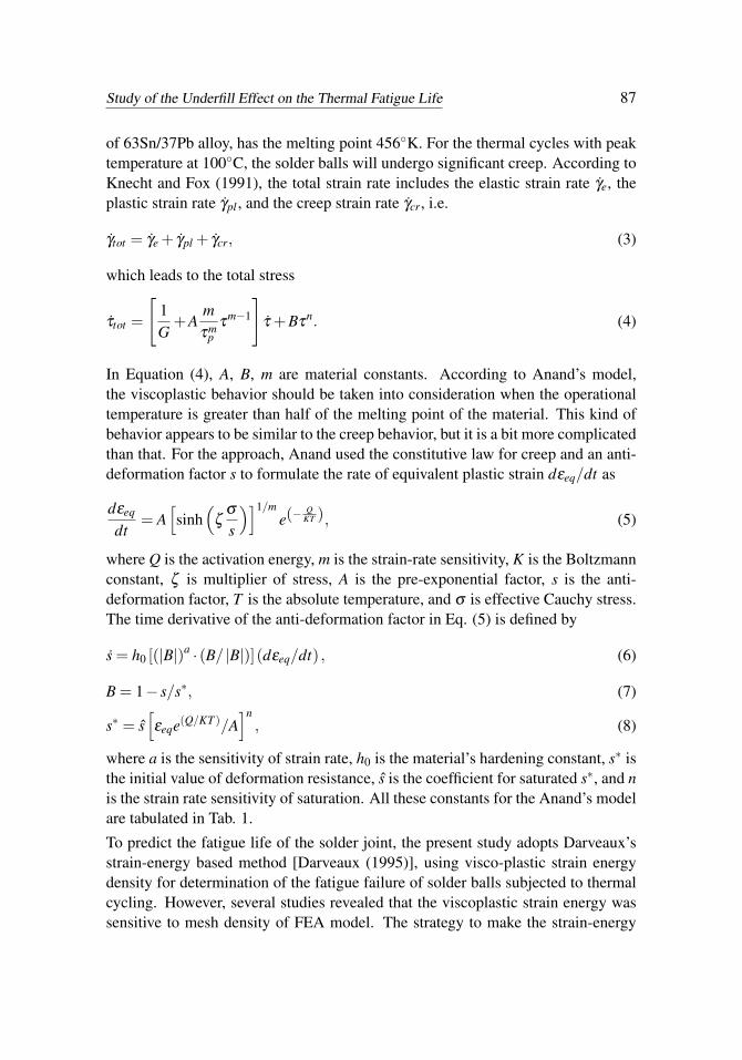
where the subscripts L and F refer to the laboratory conditions and field-use con-ditions respectively, N f (F) and N f (L) represent the fatigue life of package underfield-use and laboratory conditions respectively, ∆T is the difference between themaximum and minimum temperature in each thermal cycle, K is the Boltzamannconstant, f is the cyclic frequency within the range from 1 to 1000 cycles/day, val-ues of n and m are equal to 1.9 and 3 respectively, and Tmax is the peak temperature.Owing to the very limited power of the cooling compressor of our programmabletemperature chamber (Fig. 3 (a)), cooling the chamber temperature from 100◦C to0◦C may take up to 40 minutes for each thermal cycle.
Study of the Underfill Effect on the Thermal Fatigue Life 91
(a) (b)
Figure 3: (a) Programmable temperature chamber; (b) temperature profile
The long duration of this cooling process will significantly delay the failure of sol-der balls. For this, an extra circulating liquid cooling system, filled with industrialalcohol, is connected to the programmable temperature chamber to speed up thecooling process. Further, the cyclic temperature profile is divided into four stages:(1) temperature rising up to 100◦C, (2) constant temperature sustained at 100◦C,and (3) temperature dropping to 0◦C, and (4) constant temperature sustained at0◦C, each of which lasts approximately 14 minutes. With the added cooling sys-tem, the programmable temperature chamber is boosted to have the temperatureprofile for the four temperature stages as shown in Fig. 3(b).
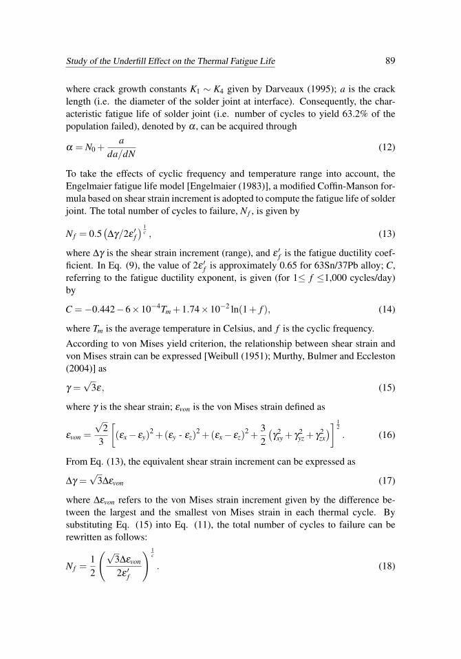
Shown in Fig. 4 is the front view of three different groups of WLCSP mountedon a printed circuit board. Each group of the same packaging type contains eightWLCSP specimens to be tested.
Figure 4: WLCSP specimens for the thermal fatigue test
92 Copyright © 2009 Tech Science Press CMES, vol.40, no.1, pp.83-103, 2009
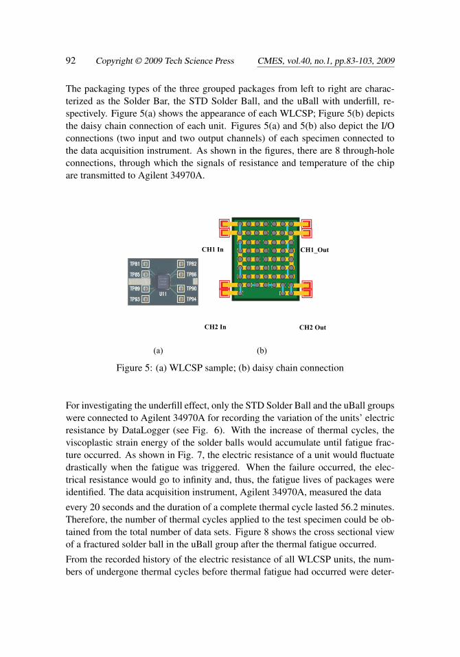
The packaging types of the three grouped packages from left to right are charac-terized as the Solder Bar, the STD Solder Ball, and the uBall with underfill, re-spectively. Figure 5(a) shows the appearance of each WLCSP; Figure 5(b) depictsthe daisy chain connection of each unit. Figures 5(a) and 5(b) also depict the I/Oconnections (two input and two output channels) of each specimen connected tothe data acquisition instrument. As shown in the figures, there are 8 through-holeconnections, through which the signals of resistance and temperature of the chipare transmitted to Agilent 34970A.
(a) (b)
CH1 In CH1_Out
CH2 In CH2 Out
Figure 5: (a) WLCSP sample; (b) daisy chain connection
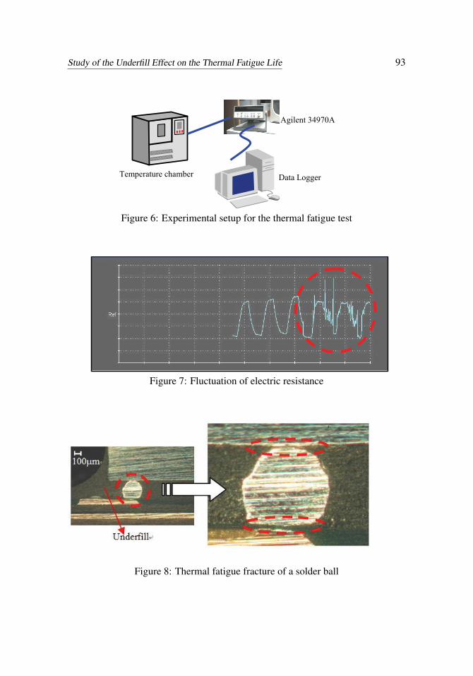
For investigating the underfill effect, only the STD Solder Ball and the uBall groupswere connected to Agilent 34970A for recording the variation of the units’ electricresistance by DataLogger (see Fig. 6). With the increase of thermal cycles, theviscoplastic strain energy of the solder balls would accumulate until fatigue frac-ture occurred. As shown in Fig. 7, the electric resistance of a unit would fluctuatedrastically when the fatigue was triggered. When the failure occurred, the elec-trical resistance would go to infinity and, thus, the fatigue lives of packages wereidentified. The data acquisition instrument, Agilent 34970A, measured the data
every 20 seconds and the duration of a complete thermal cycle lasted 56.2 minutes.Therefore, the number of thermal cycles applied to the test specimen could be ob-tained from the total number of data sets. Figure 8 shows the cross sectional viewof a fractured solder ball in the uBall group after the thermal fatigue occurred.
From the recorded history of the electric resistance of all WLCSP units, the num-bers of undergone thermal cycles before thermal fatigue had occurred were deter-
Study of the Underfill Effect on the Thermal Fatigue Life 93
Agilent 34970A
Temperature chamber Data Logger
Figure 6: Experimental setup for the thermal fatigue test
Figure 7: Fluctuation of electric resistance
Figure 8: Thermal fatigue fracture of a solder ball
94 Copyright © 2009 Tech Science Press CMES, vol.40, no.1, pp.83-103, 2009
mined for all units. Under the same experimental environment, this experiment wasconducted continuously twice for two identical PCBs, taking about six months tocomplete. The average thermal fatigue lives of the packages were found to be 1315(cycles) and 2181 (cycles) for the STD group and the uBall group, respectively.From the experimental result, it was found that the use of underfill might increasethe WLCSP’s thermal fatigue life by 65.9% or so.
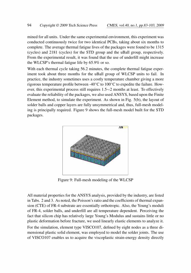
With each thermal cycle taking 56.2 minutes, the complete thermal fatigue exper-iment took about three months for the uBall group of WLCSP units to fail. Inpractice, the industry sometimes uses a costly temperature chamber giving a morerigorous temperature profile between -40◦C to 100◦C to expedite the failure. How-ever, this experimental process still requires 1.5∼2 months at least. To effectivelyevaluate the reliability of the packages, we also used ANSYS, based upon the FiniteElement method, to simulate the experiment. As shown in Fig. 5(b), the layout ofsolder balls and copper layers are fully unsymmetrical and, thus, full-mesh model-ing is principally required. Figure 9 shows the full-mesh model built for the STDpackages.
Figure 9: Full-mesh modeling of the WLCSP
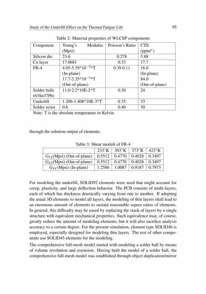
All material properties for the ANSYS analysis, provided by the industry, are listedin Tabs. 2 and 3. As noted, the Poisson’s ratio and the coefficients of thermal expan-sion (CTE) of FR-4 substrate are essentially orthotropic. Also, the Young’s moduliof FR-4, solder balls, and underfill are all temperature dependent. Perceiving thefact that silicon chip has relatively large Young’s Modulus and sustains little or noplastic deformation before fracture, we used linearly elastic elements to analyze it.
For the simulation, element type VISCO107, defined by eight nodes as a three di-mensional plastic solid element, was employed to model the solder joints. The useof VISCO107 enables us to acquire the viscoplastic strain-energy density directly
Study of the Underfill Effect on the Thermal Fatigue Life 95
Table 2: Material properties of WLCSP components
Component Young’s Modulus(Mpsi)
Poisson’s Ratio CTE(ppm/◦)
Silicon die 23.6 0.278 5.88Cu layer 17.0681 0.33 17.7FR-4 4.05-5.39*10−3*T
(In-plane)17.7-2.35*10−3*T(Out-of-plane)
0.39 0.11 16.0(In-plane)84.0(Out-of-plane)
Solder balls(63Sn37Pb)
11.0-2.2*10E-2*T 0.30 24
Underfill 1.206-1.408*10E-3*T 0.35 33Solder resist 0.6 0.40 30Note: T is the absolute temperature in Kelvin
through the solution output of elements.
Table 3: Shear moduli of FR-4233◦K 303◦K 373◦K 423◦K
GY Z(Mpsi) (Out-of-plane) 0.5512 0.4770 0.4028 0.3497GXZ(Mpsi) (Out-of-plane) 0.5512 0.4770 0.4028 0.3497
GXY (Mpsi) (In-plane) 1.2586 1.0087 0.9187 0.7973
For modeling the underfill, SOLID92 elements were used that might account forcreep, plasticity, and large deflection behavior. The PCB consists of multi-layers,each of which has thickness drastically varying from one to another. If adoptingthe usual 3D elements to model all layers, the modeling of thin layers shall lead toan enormous amount of elements to sustain reasonable aspect ratios of elements.In general, this difficulty may be eased by replacing the stack of layers by a singlestructure with equivalent mechanical properties. Such equivalence may, of course,greatly reduce the amount of modeling elements, but it will also sacrifice analysisaccuracy to a certain degree. For the present simulation, element type SOLID46 isemployed, especially designed for modeling thin layers. The rest of other compo-nents use SOLID45 elements for the modeling.
The comprehensive full-mesh model started with modeling a solder ball by meansof volume revolution and extrusion. Having built the model of a solder ball, thecomprehensive full-mesh model was established through object duplication/mirror
96 Copyright © 2009 Tech Science Press CMES, vol.40, no.1, pp.83-103, 2009
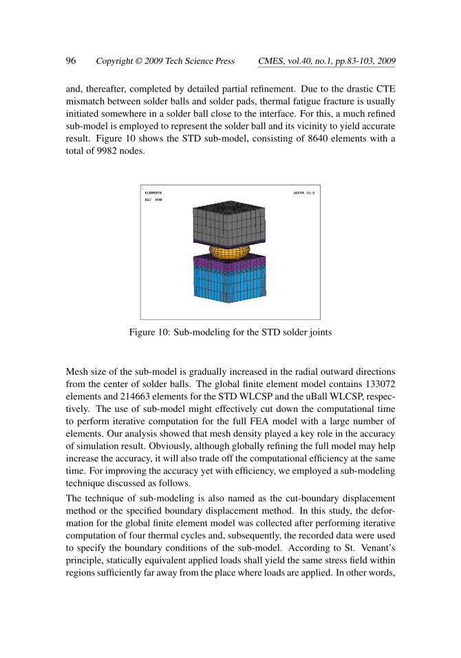
and, thereafter, completed by detailed partial refinement. Due to the drastic CTEmismatch between solder balls and solder pads, thermal fatigue fracture is usuallyinitiated somewhere in a solder ball close to the interface. For this, a much refinedsub-model is employed to represent the solder ball and its vicinity to yield accurateresult. Figure 10 shows the STD sub-model, consisting of 8640 elements with atotal of 9982 nodes.
Figure 10: Sub-modeling for the STD solder joints
Mesh size of the sub-model is gradually increased in the radial outward directionsfrom the center of solder balls. The global finite element model contains 133072elements and 214663 elements for the STD WLCSP and the uBall WLCSP, respec-tively. The use of sub-model might effectively cut down the computational timeto perform iterative computation for the full FEA model with a large number ofelements. Our analysis showed that mesh density played a key role in the accuracyof simulation result. Obviously, although globally refining the full model may helpincrease the accuracy, it will also trade off the computational efficiency at the sametime. For improving the accuracy yet with efficiency, we employed a sub-modelingtechnique discussed as follows.
The technique of sub-modeling is also named as the cut-boundary displacementmethod or the specified boundary displacement method. In this study, the defor-mation for the global finite element model was collected after performing iterativecomputation of four thermal cycles and, subsequently, the recorded data were usedto specify the boundary conditions of the sub-model. According to St. Venant’sprinciple, statically equivalent applied loads shall yield the same stress field withinregions sufficiently far away from the place where loads are applied. In other words,
Study of the Underfill Effect on the Thermal Fatigue Life 97
the stress field only varies in the loading vicinity for statically equivalent loadingsystems. Accordingly, the sub-model should still yield accurate results as long asthe boundary of the sub-model is sufficiently far away from areas of stress con-centration. The main advantage of the sub-modeling is to analyze the complicatedproblem without starting the simulation from a fine global model. For our sim-ulation, a coarse-mesh model suitable for fast computation was firstly employedto compute preliminary results; sequentially, a sub-model with fine meshes wasused to refine the results afterwards. Our numerical experiments showed that thesub-modeling would satisfactorily yield accurate results as compared with thoseobtained from a global fine model.
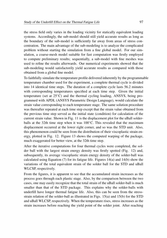
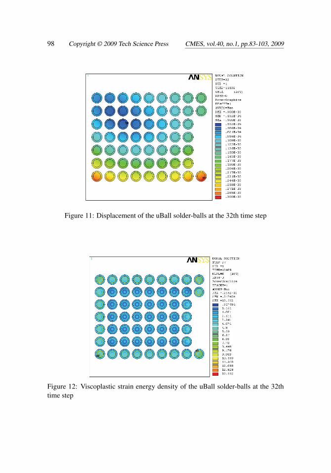
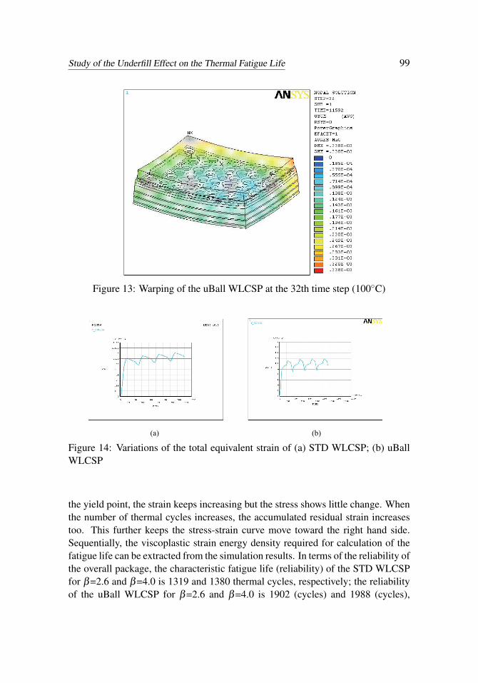
To faithfully simulate the temperature profile delivered inherently by the programmabletemperature chamber used for the experiment, a complete thermal cycle is dividedinto 14 identical time steps. The duration of a complete cycle lasts 56.2 minuteswith corresponding temperatures specified at each time step. Given the initialtemperature (set at 25◦C) and the thermal cycling loading, ANSYS, being pro-grammed with APDL (ANSYS Parametric Design Language), would calculate thestrain value corresponding to each temperature stage. The same solution procedurewas thereafter repeated at each time step except that the strain value obtained fromthe previous time step served as the initial state (condition) for calculation of thecurrent strain value. Shown in Fig. 11 is the displacement plot for the uBall solder-balls at the 32th time step when it was 100◦C. This revealed that the maximumdisplacement occurred at the lower right corner, and so was the STD unit. Also,this phenomenon could be seen from the distribution of their viscoplastic strain en-ergy, plotted in Fig. 12. Figure 13 shows the computed warping of the package,much exaggerated for better view, at the 32th time step.
After the iterative computations for four thermal cycles were completed, the sol-der ball with the largest strain energy density was firstly spotted (Fig. 12) and,subsequently, its average viscoplastic strain energy density of the solder-ball wascalculated using Equation (7) for its fatigue life. Figures 14(a) and 14(b) show thevariations of the total equivalent strain of the solder ball for the STD and uBallWLCSP, respectively.
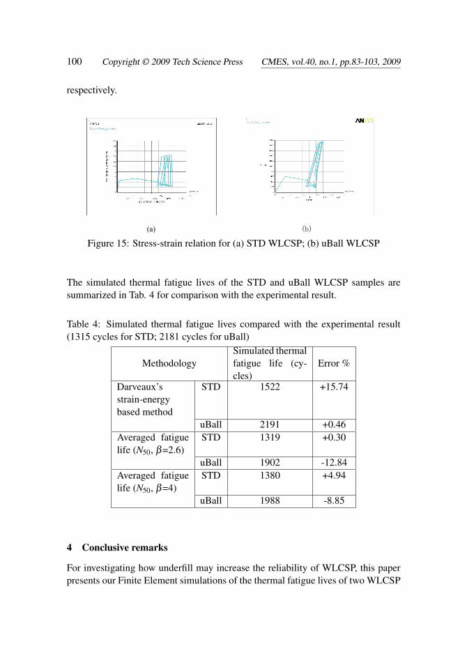
From the figures, it is apparent to see that the accumulated strain increases as theprocess goes through each plastic stage. Also, by the comparison between the twocases, one may easily recognize that the total strain of the uBall solder-ball is muchsmaller than that of the STD package. This explains why the solder-balls withunderfill have longer thermal fatigue life. Also, this can be seen from the stress-strain relation of the solder-ball as illustrated in Figs. 15(a) and 15(b) for the STDand uBall WLCSP, respectively. When the temperature rises, stress increases as thestrain increases before reaching the yield point of the solder joint. After reaching
98 Copyright © 2009 Tech Science Press CMES, vol.40, no.1, pp.83-103, 2009
Figure 11: Displacement of the uBall solder-balls at the 32th time step
Figure 12: Viscoplastic strain energy density of the uBall solder-balls at the 32thtime step
Study of the Underfill Effect on the Thermal Fatigue Life 99
Figure 13: Warping of the uBall WLCSP at the 32th time step (100◦C)
(a) (b)
Figure 14: Variations of the total equivalent strain of (a) STD WLCSP; (b) uBallWLCSP
the yield point, the strain keeps increasing but the stress shows little change. Whenthe number of thermal cycles increases, the accumulated residual strain increasestoo. This further keeps the stress-strain curve move toward the right hand side.Sequentially, the viscoplastic strain energy density required for calculation of thefatigue life can be extracted from the simulation results. In terms of the reliability ofthe overall package, the characteristic fatigue life (reliability) of the STD WLCSPfor β=2.6 and β=4.0 is 1319 and 1380 thermal cycles, respectively; the reliabilityof the uBall WLCSP for β=2.6 and β=4.0 is 1902 (cycles) and 1988 (cycles),
100 Copyright © 2009 Tech Science Press CMES, vol.40, no.1, pp.83-103, 2009
respectively.
(a) (b)
Figure 15: Stress-strain relation for (a) STD WLCSP; (b) uBall WLCSP
The simulated thermal fatigue lives of the STD and uBall WLCSP samples aresummarized in Tab. 4 for comparison with the experimental result.
Table 4: Simulated thermal fatigue lives compared with the experimental result(1315 cycles for STD; 2181 cycles for uBall)
MethodologySimulated thermalfatigue life (cy-cles)
Error %
Darveaux’sstrain-energybased method
STD 1522 +15.74
uBall 2191 +0.46Averaged fatiguelife (N50, β=2.6)
STD 1319 +0.30
uBall 1902 -12.84Averaged fatiguelife (N50, β=4)
STD 1380 +4.94
uBall 1988 -8.85
4 Conclusive remarks
For investigating how underfill may increase the reliability of WLCSP, this paperpresents our Finite Element simulations of the thermal fatigue lives of two WLCSP
Study of the Underfill Effect on the Thermal Fatigue Life 101
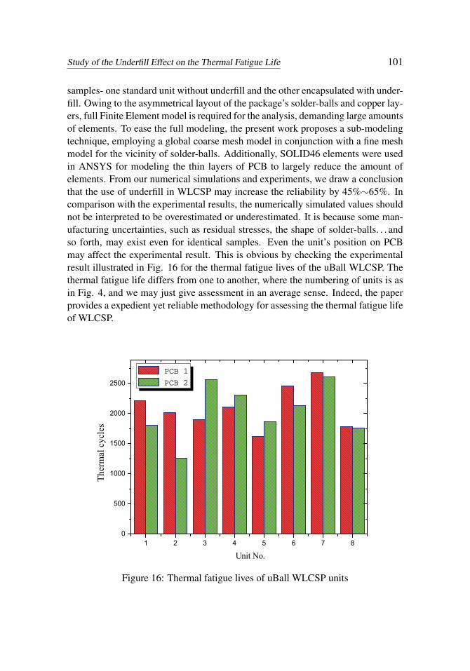
samples- one standard unit without underfill and the other encapsulated with under-fill. Owing to the asymmetrical layout of the package’s solder-balls and copper lay-ers, full Finite Element model is required for the analysis, demanding large amountsof elements. To ease the full modeling, the present work proposes a sub-modelingtechnique, employing a global coarse mesh model in conjunction with a fine meshmodel for the vicinity of solder-balls. Additionally, SOLID46 elements were usedin ANSYS for modeling the thin layers of PCB to largely reduce the amount ofelements. From our numerical simulations and experiments, we draw a conclusionthat the use of underfill in WLCSP may increase the reliability by 45%∼65%. Incomparison with the experimental results, the numerically simulated values shouldnot be interpreted to be overestimated or underestimated. It is because some man-ufacturing uncertainties, such as residual stresses, the shape of solder-balls. . . andso forth, may exist even for identical samples. Even the unit’s position on PCBmay affect the experimental result. This is obvious by checking the experimentalresult illustrated in Fig. 16 for the thermal fatigue lives of the uBall WLCSP. Thethermal fatigue life differs from one to another, where the numbering of units is asin Fig. 4, and we may just give assessment in an average sense. Indeed, the paperprovides a expedient yet reliable methodology for assessing the thermal fatigue lifeof WLCSP.
1 2 3 4 5 6 7 80
500
1000
1500
2000
2500
Ther
mal
cyc
les
Unit No.
PCB 1 PCB 2
Figure 16: Thermal fatigue lives of uBall WLCSP units
102 Copyright © 2009 Tech Science Press CMES, vol.40, no.1, pp.83-103, 2009
Acknowledgement: The authors would like to express gratitude to National Sci-ence Council of Taiwan for the financial support (NSC-96-2221-E-035-011-MY3).
References
Amagai, M. (1999): Chip scale package (CSP) solder joint reliability and model-ing, Microelectronics Reliability, Vol. 39, Issue 4, pp.463-477.
Anand, L. (1985): Constitutive equations for hot-working of metals. InternationalJournal of Plasticity, Vol. 1, pp.213-231.
Cheng, H. C.; Yu, C. Y.; Chen, W. H. (2005): An Effective Thermal-mechanicalModeling Methodology for Large-scale Area Array Typed Packages, CMES: Com-puter Modeling in Engineering & Sciences, Vol. 7, No. 1, pp.1-17.
Chiang, Kuo-Ning; Chou, Chan-Yen; Wu, Chung-Jung; Huang, Chao-Jen;Yew, Ming-Chih (2008): Analytical Solution for Estimation of Temperature-DependentMaterial Properties of Metals Using Modified Morse Potential, CMES: ComputerModeling in Engineering & Sciences, Vol. 37, No. 1, pp.85-96.
Darveaux, R. (1995): Optimizing the reliability of thin small outline package(TSOP) solder joints, Advances in Electronic Packaging, ASME, Vol. 10, No.2,pp.675-685.
Engelmaier, W. W. (1983), Fatigue life of leadless chip carrier solder joints duringpower cycling, IEEE Transactions on Components, Hybrids, and ManufacturingTechnology, Vol. 6, pp.232-237.
Knecht, S.; L.R. Fox (1991): Integrated matrix Creep£ºApplication to acceleratedtesting and lifetime prediction, In Solder Joint Reliability£ºTheory and Applica-tions, New York, 1991.
John, L.; Wang, C.P.; John, L.P.; Wataru, N. (1998), Electronic Packaging:Design, Materials, Process, and Reliability, McGraw-Hill Companies, Inc.
Lai, Yi-Shao; Wang, Tong Hong; Tsai, Han-Hui; Jen, Ming-Hwa R. (2007):Cyclic bending reliability of wafer-level chip-scale packages, Microelectronics Re-liability, Vol. 47, Issue 1, pp.111-117.
Lee, W.W.; Nguyen, L.T.; Selvaduray, G.S. (2000): Solder Joint Fatigue Mod-els: Review and Applicability to Chip Scale Packages, Microelectronics Reliability,Vol. 40, No. 2, pp.231-244.
Manson, S. S. (1996): Interfaces between Fatigue Creep and fracture, InternationalJournal of Fracture, Vol. 2, No.1, pp.327-363.
Pang, J. H. L.; Chong, D. Y. R. (2001): Flip chip on board solder joint reliabilityanalysis using 2-D and 3-D FEA models, Advanced packaging, Vol. 24, pp.499-506.
Study of the Underfill Effect on the Thermal Fatigue Life 103
Prabhakar Murthy, D. N.; Bulmer, Michael; Eccleston, John A. (2004): Weibullmodel selection for reliability modelling, Reliability Engineering & System Safety,Vol. 86, Issue 3, pp.257-267.
Sun, F.; Hochstenbach, P.; Van Driel, W.D.; Zhang, G.Q. (2008): Fracturemorphology and mechanism of IMC in Low-Ag SAC Solder/UBM (Ni(P)-Au) forWLCSP. Microelectronics Reliability, Vol. 48, Issue 8, pp.1167-1170.
Tsai,Tsung-Yueh; Lai, Yi-Shao; Yeh, Chang-Lin, Chen, Rong-Sheng (2008):Structural design optimization for board-level drop reliability of wafer-level chip-scale packages, Microelectronics Reliability, Vol. 48, Issue 5, pp757-762.
Weibull, W. (1951): A statistical distribution function of wide applicability, J.Appl. Mech.-Trans. ASME, Vol. 18(3), pp.293-297.
