study of vapour absorption system using various working fluids
TRANSCRIPT

International Journal of Science and Research (IJSR) ISSN (Online): 2319-7064
Index Copernicus Value (2013): 6.14 | Impact Factor (2015): 6.391
Volume 5 Issue 4, April 2016
www.ijsr.net Licensed Under Creative Commons Attribution CC BY
Study of Vapour Absorption System Using Various
Working Fluids
Nisha Sen1, Dr. O. K. Singh
2
1Indira Gandhi Delhi Technical University for Women, Kashmere gate, Delhi, India
2Assistant Professor, Dept. of MAE, IGDTUW, Kashmere gate New Delhi, India
Abstract: Due to ever increasing global temperature the need of refrigeration system is increasing. Now a day’s refrigeration
consumes quit a large amount of energy. Our dependency on non renewable energy resources for electricity production there is need to
develop a refrigeration system which is either independent of non renewable energy or requires a very little amount of the same. So this
problem attracted the researcher towards development of the vapour absorption system, because it is environment and eco friendly and
can use low grade energy such as solar energy, waste energy etc. besides of many advantages the absorption system has coefficient of
performance less then unity. To be served by its advantages efficiently, in recent years, research has been devoted to improvement of the
performance of vapour absorption system. In this paper a number of researches on working fluid are discussed.
Keywords: Ammonia-lithium nitrate (NH3-LiNO3), Ammonia-sodium thiocyanate (NH3-NaSCN), COP.
Notations:
COP= coefficient of performance
Q= thermal energy
m= mass flow rate
ɛ= ammonia mass fraction in solution
T= temperature
h= enthalpy
P= pressure
Subscript:
e= evaporator
a= absorber
c= condenser
g= generator
1. Introduction
The market is dominated by vapour compression system due
to its high performance. Compression system requires
mechanical energy and this is provided by electrical energy
which is produced by burning of fossil fuels. So the
consumption of conventional energy resources is very high
and its limited availability reflected in rising price of
electricity. In contrast vapour absorption system can use
renewable energy resources which are available in
abundance. Another major difference between compression
and absorption system is the working fluid used. Mostly
chlorofluorocarbons (CFC) are used by compression system
and we know that halogens are the reason for depletion of
ozone layers. The refrigerant used for the absorption system
like ammonia, water etc. are very cheap and easily available.
The restriction of the refrigerant in compression system again
makes absorption system more superior.
Above reasons make vapour absorption system an economic
option [1-4].
1.1 Principle of Vapour Absorption System
Vapour absorption system also known as heat operated
system because it uses low grade thermal energy. Binary
solution is used as a working fluid consists of refrigerant and
absorbent. Refrigeration effect is produced by connecting
two evacuated vessel fig.1 (a), left vessel containing
refrigerant and right is containing solution (refrigerant +
absorbent). Pressure is to reduce in left vessel when
refrigerant vapour is absorbed by the solution in right vessel.
The refrigeration accurse inside the left vessel due to
vaporization of refrigerant its temperature reduces. At the
same time inside the right vessel solution becomes more
dilute because of increased amount of refrigerant by
absorption. An absorption process is an exothermic process,
so to maintain the absorption capability heat must be rejected
to the surrounding.
Due to the saturation of the refrigerant the solution cannot
continue with the absorption process, and then it becomes
necessary to take out the refrigerant from the diluted solution.
For this process heat is supplied to the right vessel Fig1 (b).
The refrigerant vapour condenses by rejecting heat to the
surrounding. By these processes, heat energy is used to
produce refrigeration effect. This system is intermittent
system as it produces refrigeration effect in one step during
the entire process.
Paper ID: NOV163098 2150
International Journal of Science and Research (IJSR) ISSN (Online): 2319-7064
Index Copernicus Value (2013): 6.14 | Impact Factor (2015): 6.391
Volume 5 Issue 4, April 2016
www.ijsr.net Licensed Under Creative Commons Attribution CC BY
(a)
(b)
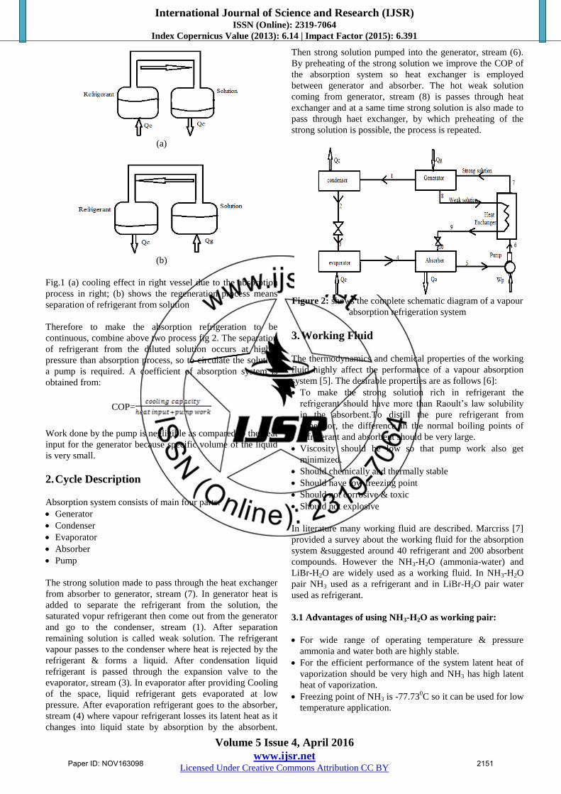
Fig.1 (a) cooling effect in right vessel due to the absorption
process in right; (b) shows the regeneration process means
separation of refrigerant from solution
Therefore to make the absorption refrigeration to be
continuous, combine above two process fig 2. The separation
of refrigerant from the diluted solution occurs at higher
pressure than absorption process, so to circulate the solution
a pump is required. A coefficient of absorption system is
obtained from:
COP=
Work done by the pump is negligible as compared to the heat
input for the generator because specific volume of the liquid
is very small.
2. Cycle Description
Absorption system consists of main four parts:
Generator
Condenser
Evaporator
Absorber
Pump
The strong solution made to pass through the heat exchanger
from absorber to generator, stream (7). In generator heat is
added to separate the refrigerant from the solution, the
saturated vopur refrigerant then come out from the generator
and go to the condenser, stream (1). After separation
remaining solution is called weak solution. The refrigerant
vapour passes to the condenser where heat is rejected by the
refrigerant & forms a liquid. After condensation liquid
refrigerant is passed through the expansion valve to the
evaporator, stream (3). In evaporator after providing Cooling
of the space, liquid refrigerant gets evaporated at low
pressure. After evaporation refrigerant goes to the absorber,
stream (4) where vapour refrigerant losses its latent heat as it
changes into liquid state by absorption by the absorbent.
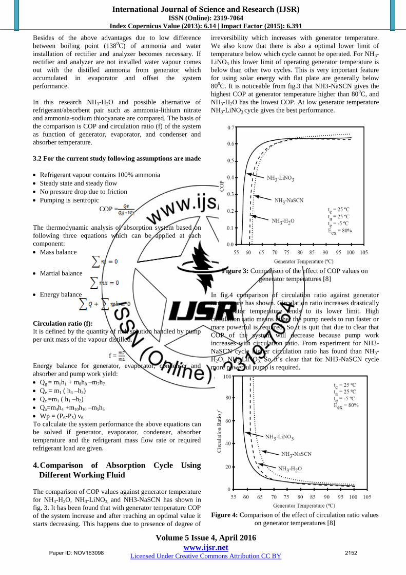
Then strong solution pumped into the generator, stream (6).
By preheating of the strong solution we improve the COP of
the absorption system so heat exchanger is employed
between generator and absorber. The hot weak solution
coming from generator, stream (8) is passes through heat
exchanger and at a same time strong solution is also made to
pass through haet exchanger, by which preheating of the
strong solution is possible, the process is repeated.
Figure 2: shows the complete schematic diagram of a vapour
absorption refrigeration system
3. Working Fluid
The thermodynamics and chemical properties of the working
fluid highly affect the performance of a vapour absorption
system [5]. The desirable properties are as follows [6]:
To make the strong solution rich in refrigerant the
refrigerant should have more than Raoult’s law solubility
in the absorbent.To distill the pure refrigerant from
generator, the difference in the normal boiling points of
refrigerant and absorbent should be very large.
Viscosity should be low so that pump work also get
minimized.
Should chemically and thermally stable
Should have low freezing point
Should not corrosive & toxic
Should not explosive
In literature many working fluid are described. Marcriss [7]
provided a survey about the working fluid for the absorption
system &suggested around 40 refrigerant and 200 absorbent
compounds. However the NH3-H2O (ammonia-water) and
LiBr-H2O are widely used as a working fluid. In NH3-H2O
pair NH3 used as a refrigerant and in LiBr-H2O pair water
used as refrigerant.
3.1 Advantages of using NH3-H2O as working pair:
For wide range of operating temperature & pressure
ammonia and water both are highly stable.
For the efficient performance of the system latent heat of
vaporization should be very high and NH3 has high latent
heat of vaporization.
Freezing point of NH3 is -77.730C so it can be used for low
temperature application.
Paper ID: NOV163098 2151
International Journal of Science and Research (IJSR) ISSN (Online): 2319-7064
Index Copernicus Value (2013): 6.14 | Impact Factor (2015): 6.391
Volume 5 Issue 4, April 2016
www.ijsr.net Licensed Under Creative Commons Attribution CC BY
Besides of the above advantages due to low difference
between boiling point (1380C) of ammonia and water
installation of rectifier and analyzer becomes necessary. If
rectifier and analyzer are not installed water vapour comes
out with the distilled ammonia from generator which
accumulated in evaporator and offset the system
performance.
In this research NH3-H2O and possible alternative of
refrigerant/absorbent pair such as ammonia-lithium nitrate
and ammonia-sodium thiocyanate are compared. The basis of
the comparison is COP and circulation ratio (f) of the system
as function of generator, evaporator, and condenser and
absorber temperature.
3.2 For the current study following assumptions are made
Refrigerant vapour contains 100% ammonia
Steady state and steady flow
No pressure drop due to friction
Pumping is isentropic
COP =
The thermodynamic analysis of absorption system based on
following three equations which can be applied at each
component:
Mass balance
Martial balance
Energy balance
Circulation ratio (f):
It is defined by the quantity of rich solution handled by pump
per unit mass of the vapour distilled.
f =
Energy balance for generator, evaporator, condenser and
absorber and pump work yield:
Qg = m1h1 + m8h8 –m7h7
Qe = m1 ( h4 –h3)
Qc =m1 ( h1 –h2)
Qa=m4h4 +m10h10 –m5h5
Wp = (P6-P5) v6
To calculate the system performance the above equations can
be solved if generator, evaporator, condenser, absorber
temperature and the refrigerant mass flow rate or required
refrigerant load are given.
4. Comparison of Absorption Cycle Using
Different Working Fluid
The comparison of COP values against generator temperature
for NH3-H2O, NH3-LiNO3, and NH3-NaSCN has shown in
fig. 3. It has been found that with generator temperature COP
of the system increase and after reaching an optimal value it
starts decreasing. This happens due to presence of degree of
irreversibility which increases with generator temperature.
We also know that there is also a optimal lower limit of
temperature below which cycle cannot be operated. For NH3-
LiNO3 this lower limit of operating generator temperature is
below than other two cycles. This is very important feature
for using solar energy with flat plate are generally below
800C. It is noticeable from fig.3 that NH3-NaSCN gives the
highest COP at generator temperature higher than 800C, and
NH3-H2O has the lowest COP. At low generator temperature
NH3-LiNO3 cycle gives the best performance.
Figure 3: Comparison of the effect of COP values on
generator temperatures [8]
In fig.4 comparison of circulation ratio against generator
temperature has shown. Circulation ratio increases drastically
if generator temperature tends to its lower limit. High
circulation ratio means either the pump needs to run faster or
mare powerful is required. So it is quit that due to clear that
COP of the system will decrease because pump work
increases with circulation ratio. From experiment for NH3-
NaSCN cycle higher circulation ratio has found than NH3-
H2O, NH3-LiNO3. So it’s clear that for NH3-NaSCN cycle
more powerful pump is required.
Figure 4: Comparison of the effect of circulation ratio values
on generator temperatures [8]
Paper ID: NOV163098 2152

International Journal of Science and Research (IJSR) ISSN (Online): 2319-7064
Index Copernicus Value (2013): 6.14 | Impact Factor (2015): 6.391
Volume 5 Issue 4, April 2016
www.ijsr.net Licensed Under Creative Commons Attribution CC BY
The comparison of the COP of the system varies with the
evaporator temperature has shown in fig. 5. The COP of the
system increases with evaporator temperature. Below the
zero evaporator temperature NH3-H2O has lowest system
performance but it has better performance than NH3-LiNO3 at
higher evaporator temperature. From fig.5 it is clear that
NH3-NaSCN has better performance at below zero
evaporator temperature.
Figure 5: Comparison of the effect of COP values on
evaporator temperatures [8]
The circulation ratio plotted against evaporator temperature
in fig.6. From the fig it is very clear that NH3-NaSCN system
has higher circulation ratio.
Figure 6: Comparison of the effect of circulation ratio values
on evaporator temperatures [8]
We already know that with increasing temperature of
condenser refrigeration effect decreases. From fig.7 it is
clearly visible that COP of the three system decreases with
increasing temperature of condenser. But for the same
temperature range NH3-NaSCN andNH3-LiNO3 has better
performance than NH3-H2O. At low condenser temperature
NH3-NaSCN has better performance while at high condenser
temperature NH3-LiNO3 has the better performance. In fig.8
circulation ratio v/s condenser temperature has been plotted
and again NH3-NaSCN has higher circulation ratio. From
fig.9 it is clear that the effect of condenser temperature and
absorber temperature are similar. Generally the temperature
level remains same for both the condenser and absorber. The
comparison between the NH3-H2O, NH3-LiNO3 and NH3-
NaSCN cycle on the basis of circulation ratio v/s absorber
temperature has been shown in fig.9.
Figure 7: Comparison of the effect of COP values on
condenser temperatures [8]
Figure 8: Comparison of the effect of circulation ratio values
on condenser temperatures [8]
Figure 9: Comparison of the effect of COP values on
absorber temperatures [8]
Paper ID: NOV163098 2153
International Journal of Science and Research (IJSR) ISSN (Online): 2319-7064
Index Copernicus Value (2013): 6.14 | Impact Factor (2015): 6.391
Volume 5 Issue 4, April 2016
www.ijsr.net Licensed Under Creative Commons Attribution CC BY
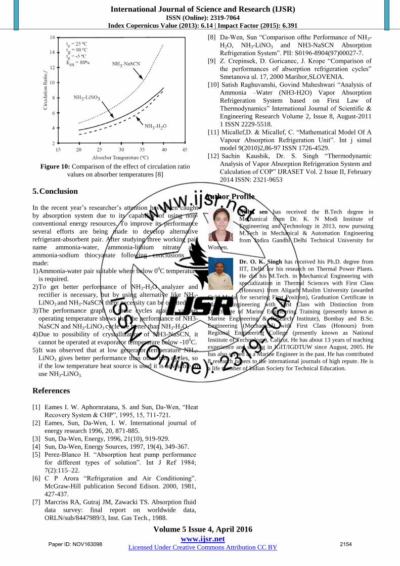
Figure 10: Comparison of the effect of circulation ratio
values on absorber temperatures [8]
5. Conclusion
In the recent year’s researcher’s attention have been caught
by absorption system due to its capability of using non-
conventional energy resources. To improve its performance
several efforts are being made to develop alternative
refrigerant-absorbent pair. After studying three working pair
name ammonia-water, ammonia-lithium nitrate and
ammonia-sodium thiocyanate following conclusions are
made:
1) Ammonia-water pair suitable where below 00C temperature
is required.
2) To get better performance of NH3-H2O analyzer and
rectifier is necessary, but by using alternative like NH3-
LiNO3 and NH3-NaSCN there necessity can be omitted.
3) The performance graph of these cycles against various
operating temperature shows that the performance of NH3-
NaSCN and NH3-LiNO3 cycle are better than NH3-H2O.
4) Due to possibility of crystallization of NH3-NaSCN, it
cannot be operated at evaporator temperature below -100C.
5) It was observed that at low generator temperature NH3-
LiNO3 gives better performance than other two cycles, so
if the low temperature heat source is used it is advisable to
use NH3-LiNO3.
References
[1] Eames I. W. Aphornratana, S. and Sun, Da-Wen, “Heat
Recovery System & CHP”, 1995, 15, 711-721.
[2] Eames, Sun, Da-Wen, I. W. International journal of
energy research 1996, 20, 871-885.
[3] Sun, Da-Wen, Energy, 1996, 21(10), 919-929.
[4] Sun, Da-Wen, Energy Sources, 1997, 19(4), 349-367.
[5] Perez-Blanco H. “Absorption heat pump performance
for different types of solution”. Int J Ref 1984;
7(2):115–22.
[6] C P Arora “Refrigeration and Air Conditioning”.
McGraw-Hill publication Second Edison. 2000, 1981,
427-437.
[7] Marcriss RA, Gutraj JM, Zawacki TS. Absorption fluid
data survey: final report on worldwide data,
ORLN/sub/8447989/3, Inst. Gas Tech., 1988.
[8] Da-Wen, Sun “Comparison ofthe Performance of NH3-
H2O, NH3-LiNO3 and NH3-NaSCN Absorption
Refrigeration System”. PII: S0196-8904(97)00027-7.
[9] Z. Crepinsek, D. Goricanec, J. Krope “Comparison of
the performances of absorption refrigeration cycles”
Smetanova ul. 17, 2000 Maribor,SLOVENIA.
[10] Satish Raghuvanshi, Govind Maheshwari “Analysis of
Ammonia –Water (NH3-H2O) Vapor Absorption
Refrigeration System based on First Law of
Thermodynamics” International Journal of Scientific &
Engineering Research Volume 2, Issue 8, August-2011
1 ISSN 2229-5518.
[11] Micallef,D. & Micallef, C. “Mathematical Model Of A
Vapour Absorption Refrigeration Unit”. Int j simul
model 9(2010)2,86-97 ISSN 1726-4529.
[12] Sachin Kaushik, Dr. S. Singh “Thermodynamic
Analysis of Vapor Absorption Refrigeration System and
Calculation of COP” IJRASET Vol. 2 Issue II, February
2014 ISSN: 2321-9653
Author Profile
Nisha sen has received the B.Tech degree in
Mechanical from Dr. K. N Modi Institute of
Engineering and Technology in 2013, now pursuing
M.Tech in Mechanical & Automation Engineering
from Indira Gandhi Delhi Technical University for
Women.
Dr. O. K. Singh has received his Ph.D. degree from
IIT, Delhi for his research on Thermal Power Plants.
He did his M.Tech. in Mechanical Engineering with
specialization in Thermal Sciences with First Class
(Honours) from Aligarh Muslim University (awarded
Gold Medal for securing First Position), Graduation Certificate in
Marine Engineering with First Class with Distinction from
Directorate of Marine Engineering Training (presently known as
Marine Engineering & Research Institute), Bombay and B.Sc.
Engineering (Mechanical) with First Class (Honours) from
Regional Engineering College (presently known as National
Institute of Technology), Calicut. He has about 13 years of teaching
experience and serving in IGIT/IGDTUW since August, 2005. He
has also served as a Marine Engineer in the past. He has contributed
8 research papers to the international journals of high repute. He is
a life member of Indian Society for Technical Education.
Paper ID: NOV163098 2154