study on effects of supply voltage asymmetry and
TRANSCRIPT

Louisiana State UniversityLSU Digital Commons
LSU Master's Theses Graduate School
2013
Study on effects of supply voltage asymmetry anddistortion on induction machinePrashanna Dev BhattaraiLouisiana State University and Agricultural and Mechanical College, [email protected]
Follow this and additional works at: https://digitalcommons.lsu.edu/gradschool_theses
Part of the Electrical and Computer Engineering Commons
This Thesis is brought to you for free and open access by the Graduate School at LSU Digital Commons. It has been accepted for inclusion in LSUMaster's Theses by an authorized graduate school editor of LSU Digital Commons. For more information, please contact [email protected].
Recommended CitationBhattarai, Prashanna Dev, "Study on effects of supply voltage asymmetry and distortion on induction machine" (2013). LSU Master'sTheses. 1955.https://digitalcommons.lsu.edu/gradschool_theses/1955

STUDY ON EFFECTS OF SUPPLY VOLTAGE ASYMMETRY AND DISTORTION ON
INDUCTION MACHINE
A Thesis
Submitted to the Graduate Faculty of the
Louisiana State University and
Agricultural and Mechanical College
in partial fulfillment of the
requirements for the degree of
Master of Science in Electrical Engineering
In
The Department of Electrical and Computer Engineering
by
Prashanna Dev Bhattarai
Bachelor of Electrical Engineering, Tribhuvan University, Nepal, 2008
May 2013

ii
ACKNOWLEDGEMENTS
I would like to thank all my friends and colleagues for supporting me in my academic and
social undertakings. I would especially like to thank my colleagues at Louisiana State University
for their endless support and guidance during the pursuit of this thesis. I would like to mention
Mr Tracy Toups, Mr Paul Haley and Mr. Kashi Ram Kafle. My special thanks go to Jyotsaana,
who has been by my side throughout my endeavors.
I would also like to convey my thanks to the Department of Electrical Engineering of
Louisiana State University for providing me with an opportunity to pursue my higher studies. I
am committed to repaying back with my academic achievements.
I am grateful to Dr. Ernest Mendrela, Dr. Shahab Mehraeen and Mr Mike McAnelly for
agreeing to be a part of my committee and for all the help and guidance they have provided.
My utmost respect and appreciation goes to my major professor Dr Leszek Czarnecki, for
whom I have high regards, both academic and personal. I feel privileged to work under his
guidance and for all the support I have received from him and his wife Mrs Maria Czarnecka.
I thank God for providing me with all the intellect, health and opportunities to this day.
Above all, I would like to express my love and gratefulness towards my parents, Manju
and Kalyan, to whom I owe everything. Thank you for providing me with wonderful
opportunities, righteous values and everlasting support. I feel honored to have you as my parents.
Thanks a lot!

iii
TABLE OF CONTENTS
ACKNOWLEDGEMENTS ............................................................................................................ ii
LIST OF TABLES ....................................................................................................................... vii
LIST OF FIGURES ...................................................................................................................... ix
ABSTRACT .................................................................................................................................. xi
CHAPTER 1: INTRODUCTION ....................................................................................................1
1.1 Background on induction machines .......................................................................................1
1.2 Thesis subject .........................................................................................................................3
1.3 Thesis objective and approach ..............................................................................................3
CHAPTER 2: OPERATION OF INDUCTION MACHINE UNDER IDEAL VOLTAGE
SUPPLY ...........................................................................................................................................4
2.1 Introduction ............................................................................................................................4
2.2 Generation of circular rotating magnetic field in the air gap ................................................4
2.3 Rotor slip ...............................................................................................................................7
2.4 Single phase equivalent circuit of induction machines .........................................................8
2.5 Power relations in induction machines ................................................................................12
2.6 Torque .................................................................................................................................13
2.7 Efficiency ............................................................................................................................15
CHAPTER 3: OPERATION OF INDUCTION MACHINES UNDER ASYMMETRICAL
SUPPLY VOLTAGE .....................................................................................................................16
3.1 Introduction ..........................................................................................................................16
3.2 Causes of voltage asymmetry ...............................................................................................17
3.2.1 Structural asymmetry .....................................................................................................18
3.2.2 Voltage asymmetry as a response to current asymmetry .............................................18

iv
3.3 Measures of voltage asymmetry ..........................................................................................19
3.4 Limitations of the single phase equivalent circuit of induction machines ..........................20
3.5 Equivalent circuit of the machine under sinusoidal asymmetrical supply voltage .............21
3.6 Analysis of machine performance under asymmetrical supply ..........................................22
3.6.1 Torque ...........................................................................................................................24
3.6.2 Rotor Currents ..............................................................................................................27
3.6.3 Losses ...........................................................................................................................29
3.6.4 Efficiency .....................................................................................................................31
3.6.5 Life expectancy and de-rating of machines ..................................................................33
CHAPTER 4: OPERATION OF INDUCTION MACHINES UNDER DISTORTED SUPPLY
VOLTAGE .....................................................................................................................................34
4.1 Introduction ..........................................................................................................................34
4.2 Types and causes of voltage and current distortion .............................................................34
4.2.1 Distortions originating at the generation level .............................................................35
4.2.2 Interaction of voltage and current distortion ................................................................35
4.2.3 Non-linear loads ...........................................................................................................36
4.3 Mathematical representation of a distorted quantity ...........................................................36
4.4 Measures of voltage and current distortion .........................................................................41
4.5 Limitations of the single phase equivalent circuit of induction machines ..........................41
4.6 Equivalent circuit of the machine under sinusoidal asymmetrical supply voltage .............42
4.7 Analysis of machine performance under asymmetrical supply ..........................................44
4.7.1 Torque ...........................................................................................................................46
4.7.2 Rotor Currents ..............................................................................................................50
4.7.3 Losses ...........................................................................................................................52
v
4.7.4 Efficiency .....................................................................................................................54
4.7.5 Life expectancy and de-rating of machines ..................................................................55
CHAPTER 5: COMPUTER MODELLING AND RESULTS .....................................................56
5.1 Introduction ..........................................................................................................................56
5.2 Modeling of induction machine under sinusoidal symmetrical supply voltage ...................57
5.3 Modeling of induction machine under asymmetrical sinusoidal supply voltage .................58
5.3.1 Output torque ...............................................................................................................58
5.3.2 Performance of machine when connected to a load of constant torque .......................60
5.3.2.1 Speed .....................................................................................................................60
5.3.2.2 Losses ....................................................................................................................61
5.3.2.3 Efficiency and power relations ..............................................................................64
5.3.2.4 Current response of induction machine .................................................................67
5.4 Modeling of induction machine under symmetrical distorted supply voltages ...................69
5.4.1 Output torque ..............................................................................................................70
5.4.2 Performance of machine when connected to a load of constant torque ......................73
5.4.2.1 Speed ....................................................................................................................73
5.4.2.2 Machine equivalent impedance ............................................................................73
5.4.2.3 Current response of induction machine ................................................................74
5.4.2.4 Losses ...................................................................................................................76
5.4.2.5 Efficiency and power relations .............................................................................77
5.5 Modeling of induction machine under asymmetrical sinusoidal supply voltage .................81
5.6 Conclusion ............................................................................................................................82
CHAPTER 6: CONCLUSION .....................................................................................................83

vi
REFERENCES .............................................................................................................................84
APPENDIX A : NEMA MG-1 STANDARD FOR MACHINES AND GENERATORS DESIGN
PARAMETERS ............................................................................................................................85
APPENDIX B: MATLAB CODE FOR STUDYING THE RESPONSE OF THE MACHINE
UNDER SUPPLY VOLTAGE ASYMMETRY ..........................................................................86
APPENDIX C: MATLAB CODE FOR STUDYING THE RESPONSE OF THE MACHINE
UNDER SUPPLY VOLTAGE DISTORTION ............................................................................89
VITA .............................................................................................................................................94
vii
LIST OF TABLES
Table 5.1 Starting and maximum torque at varying VUF ............................................................59
Table 5.2 Operating speed and slips at varying VUF ...................................................................60
Table 5.3 Losses occurring in the machine at varying VUF .........................................................61
Table 5.4 Increment in losses at varying VUF .............................................................................62
Table 5.5 Losses due to the positive sequence at varying VUF ...................................................63
Table 5.6 Efficiency at varying VUF ............................................................................................64
Table 5.7 Machine power relations at varying VUF .....................................................................65
Table 5.8 Power relations in the air gap at varying VUF .............................................................66
Table 5.9 Currents in the stator and rotor of the machine at varying VUF ..................................67
Table 5.10 Machine output torques at varying THD levels ..........................................................72
Table 5.11 Machine speed and slips at varying THD levels .........................................................73
Table 5.12 Machine equivalent impedance for different harmonics ............................................74
Table 5.13 Machine currents at varying THD levels for fifth harmonic ......................................75
Table 5.14 Currents at varying THD levels for seventh harmonic ...............................................75
Table 5.15 Losses in the machine at varying THD levels for fifth harmonic ...............................76
Table 5.16 Increment in losses for varying THD levels for fifth harmonic .................................77
Table 5.17 Losses in the machine at varying THD levels for seventh harmonic VUF ................77
Table 5.18 Efficiency of the machine at varying THD levels ......................................................78
Table 5.19 Power relations in the machine at varying THD levels for fifth harmonic .................78

viii
Table 5.20 Power relation in the machine at varying THD level for seventh harmonic ..............79
Table 5.21 Power relations in the air gap at varying THD levels for fifth harmonic ...................79
Table 5.22 Power relations in the air gap at varying THD levels for seventh harmonic ..............80
Table 5.23 Comparison of effects of voltage asymmetry and distortion ......................................81

ix
LIST OF FIGURES
Figure 2.1: Layout of a 2 pole three phase stator winding ..............................................................5
Figure 2.2: Stator equivalent circuit of induction machine .............................................................9
Figure 2.3: Equivalent circuit of rotor of an induction machine ...................................................10
Figure 2.4: Single phase equivalent circuit of three phase induction machine .............................11
Figure 2.5: T-S curve of induction machine showing the different regions of operation .............14
Figure 3.1: Single phase equivalent circuit of induction machine ................................................20
Figure 3.2: Positive sequence equivalent circuit ...........................................................................22
Figure 3.3: Negative sequence equivalent circuit .........................................................................22
Figure 4.1: Representation of a distorted quantity as the sum of two sinusoidal quantities .........36
Figure 4.2: Single phase equivalent circuit of induction machine for sinusoidal symmetrical
supply voltages ..............................................................................................................................42
Figure 4.3: Single phase equivalent circuit of induction machine for fundament component .....43
Figure 4.4: Single phase equivalent circuit of induction machine for the fifth harmonic
component .....................................................................................................................................43
Figure 4.5: Single phase equivalent circuit of induction machine for the seventh harmonic
component .....................................................................................................................................43
Figure 5.1: Torque slip plot of induction machine at symmetrical sinusoidal voltage .................57
Figure 5.2: T-S plot of induction machine at varying levels of VUF ...........................................58
Figure 5.3: Starting torque at varying VUF ..................................................................................59
Figure 5.4: Plot of the total losses at varying VUF .......................................................................62
Figure 5.5: Plot of efficiency of machine at varying VUF ...........................................................64

x
Figure 5.6: Plot of CUF in stator current at varying VUF ............................................................68
Figure 5.7: Plot of the torques produced by the fundamental and seventh harmonic component
at varying THD .............................................................................................................................70
Figure 5.8: T-S plot at varying THD levels for the seventh harmonic .........................................71
Figure 5.9: Starting torques at various THD levels for seventh harmonic ...................................71
Figure 5.10: T-S plot for varying THD for fifth harmonic ...........................................................72
xi
ABSTRACT
Performance of induction motor supplied with asymmetrical and nonsinusoidal supply
voltages is studied in this thesis.
Theory of induction motor is first presented for sinusoidal symmetrical supply voltages.
Equations for the torque, losses, currents and efficiency are derived. Appropriate changes are
made to apply this theory to induction motors operating at nonsinusoidal and asymmetrical
supply voltages. Single phase equivalent circuit of the induction motor is presented for both
asymmetrical and nonsinusoidal supply voltages. The equations governing operating
characteristics are presented. Machine torque, losses, current and efficiency for asymmetrical and
nonsinusoidal supply voltages are compared with the same for sinusoidal symmetrical supply
voltages. Computer simulation in MATLAB is used to study the impacts of asymmetrical and
nonsinusoidal supply voltages on induction machines. Machine torque, losses, current and
efficiency are calculated for various levels of voltage asymmetry and distortion. Results of
computer simulation are presented.

1
CHAPTER 1: INTRODUCTION
1.1 Background on induction machines
With an increase in the level of harmonic distortion in distribution system, also often with the
voltage asymmetry, induction motors, the most common motors in customer loads, can be
affected. About two thirds of the total energy consumed in the United States flows through AC
induction machines. They are common in industry because of their features like simplicity of
operation, ruggedness of construction and low manufacturing costs. It is also equally important
that they operate efficiently and reliably.
A lot of studies have been done on induction machines in the last century and a thorough
understanding of their properties has already been build. However, most of the studies have been
done under the assumption that the machine operates under a symmetrical three phase supply
voltage with no distortion. They are designed to work efficiently under sinusoidal and
symmetrical supply. A substantial deviation from it can be fatal to the machine.
Presently, a lot of development has been done in power electronics and therefore, there is
a lot of power electronic equipment commonly present in the power system. This equipment is
responsible for causing current and voltage distortion. Loads like computers and fluorescent
lamps also contribute to distortion. Arc furnaces, which are huge single phase loads, also cause a
lot of voltage distortions.
Voltage asymmetry can originate from structural asymmetry and load unbalance.
Structural asymmetry means that the elements in the power system aren’t symmetrical.( e.g.
three lines of a three phase system, three legs of a transformer etc). Moreover, when the load is
unbalanced, it draws unbalanced current causing voltage asymmetry.

2
The current power system is a huge system that has thousands of generating units and an
interconnected network of transmission lines. About two thirds of the total load is induction
machine load. Such type of a big power system is stiff and is not heavily affected by distortion
and asymmetry. However, when a power system is operating in an islanded mode or operating as
an independent microgrid, the short circuit power is lower than that of the common power
system and the system impedance is relatively high. Such a system could be more susceptible to
voltage asymmetry and distortions. Also, the concentration of renewables with power electronic
interphase could be relatively higher in a microgrid. Thus the impact of asymmetry and
distortion on induction machines can potentially be higher in an isolated microgrid.
An induction machine is designed to work under sinusoidal symmetrical voltage supply.
Such a voltage will create a circular rotating magnetic flux in the air gap when supplied to the
stator of the machine. This air gap flux induces voltages in the rotor circuit. If the rotor circuit is
closed, current can flow in the rotor circuit and the interaction of magnetic fields created by the
stator and the rotor produces a rotating torque. When the supply voltage is asymmetrical, it can
be decomposed into positive and negative sequence components. Both of these components will
create a circular rotating flux in the air gap but the flux created by the negative sequence
component rotates in the opposite direction with respect to the flux created by the positive
sequence. It creates a negative torque which tries to rotate the rotor in the opposite direction.
The negative sequence component cannot convey energy to the motor mechanical load.
This energy is dissipated as losses. As a result, the machine torque is reduced and losses are
increased. Similarly, when the supply voltage is distorted, it has harmonic components in
addition to the fundamental. When supplied to the stator of the machine, the fundamental
component creates a rotating flux in the gap whose frequency is governed by the supply

3
frequency. Each harmonic creates a flux in the gap which rotates ‘n’ times faster than the rotor,
where n is the order of harmonic. Depending on the sequence of the harmonic, the rotating flux
rotates in the same direction as the rotor or in the opposite direction. The flux of the n order
harmonic tries to rotate the rotor many times faster than the fundamental. Since it is not able to
do so, most of the energy carried by harmonics goes to losses. From the point of view of the flux
produced by harmonics and the negative sequence voltage the machine is in a locked rotor state.
Neither the flux created by the negative sequence, nor the harmonics, contributes to
electromechanical energy conversion. Rather; it only contributes to losses.
1.2 Thesis subject
The subject of this thesis is induction machine operating under asymmetrical and distorted
supply voltage. This includes the impact of supply voltage asymmetry and load imbalance on the
machine torque, current response and efficiency.
1.3 Thesis objective and approach
The objective of this thesis is to find out the impact of supply voltage asymmetry and distortion
on the operation of induction machines. It includes finding out the mathematical relations that
can predict the degree of these impacts. Because of the supply voltage asymmetry and distortion
are expected to have different types of impacts on the machine, their impacts will be studied
individually. Mathematical equations that relate both supply voltage asymmetry and distortion to
the induction machine performance will be developed and their impacts will be studied using
simulation in MATLAB. Results from prior studies will be used as references.
4
CHAPTER 2: OPERATION OF INDUCTION MACHINE UNDER IDEAL VOLTAGE
SUPPLY
2.1 Introduction
This chapter presents the basics of induction machine operation. It does not introduce any new
ideas; rather it explains the theory that is fundamental for operation of induction machines as
well as this chapter introduces symbols and conventions used in this thesis for induction
machines description. It would build a bridge into the forthcoming chapters. Induction machines
theory presented in this chapter is mainly based on Refs. [2], [3] and [4].
When the stator winding of induction machine is supplied with three phase symmetrical
voltage, a circular rotating magnetic field is created in the air gap. This flux induces voltage in
the rotor windings. If the rotor winding is kept stationary, induction machine acts like a three
phase transformer, where the stator winding is the primary and the rotor winding is a secondary
winding. If the rotor circuit is closed by impedance or short circuited, current flows in the rotor
winding. The rotor currents also produce a magnetic field. The interaction of the two fields
creates a mechanical torque which acts towards aligning magnetic field of the rotor currents with
the field of the stator currents. Since, the stator field is rotating, the rotor follows it and hence a
rotatory motion of the rotor is achieved.
2.2 Generation of circular rotating magnetic field in the air gap
The stator of an induction machine has distributed windings. If the stator windings are supplied
with a voltage, it produces a magnetic field in the air gap which is distributed over the space. If a
single winding is supplied with time varying sinusoidal voltage source, the flux can be
approximated by the formula:

5
where,
m is the maximum value of the flux
is angle associated with the space distribution of windings, explained in Fig. 2.1.
is the angular frequency of the supply voltage.
Eqn. (2.1) can be rearranged to the form
Eqn. (2.2) describes the air gap flux of a single winding.
The stator of a three phase machine consists of three symmetrical windings displaced
from each other in space by 120 degrees. A simplified two pole three phase stator winding is
shown in Figure 2.1.
Figure 2.1: Layout of a 2 pole three phase stator winding

6
When a three phase stator winding, as shown in Fig. 2.1, is supplied with a symmetrical
three phase voltage, all the three windings produce air gap fluxes. The flux due to phase A is
due to phase B is
(
) (
)
and due to phase C is
(
) (
)
Equations (2.3) – (2.5) can be rearranged to the form:
(
)
and
(
)
The total air gap flux in the air gap ( is the sum of the fluxes created by individual
windings, i.e., the sum of fluxes in specified by eqns. (2.6), (2.7) and (2.8) This sum is equal to
Eqn. (2.9) gives the expression for the total air gap flux when the stator windings are supplied
with symmetrical sinusoidal voltages. Thus, the flux in the air gap of the machine is therefore a
circular rotating flux.

7
The angular rotating speed of the rotating field is
where
f is the frequency of supply voltage
p is the number of pole pairs
The RMS value of the voltage induced in the rotor winding is equal to
√
where,
k is winding factor
N is number of turns in series per phase
is air gap magnetic flux per pole
2.3 Rotor slip
At a motor start, the rotor is at standstill. As explained earlier, when the magnetic flux in the
rotor windings change with time, a voltage is generated in the rotor. This voltage is generated as
a result of induction and hence the name induction motors. At standstill the frequency of the
voltage in the rotor is equal to the frequency of the supply voltage or angular frequency .
Just like the stator, a wound rotor also has three phase symmetrical windings. Likewise, the rotor
windings are excited by induced by symmetrical three phase voltages that are shifted mutually in
time by one third of the period T. Therefore, in accordance to the principles discussed earlier in
this chapter, the rotor currents also create a circular rotating magnetic flux in the gap. At
standstill, the angular frequency of the air gap flux created by the rotor is also ωs. Since there are
two fields in the air gap, they interact with each other and this interaction results in creating a

8
torque. And as explained earlier, since the rotor is movable, this torque rotates the rotor. It should
be noted that for the rotation to occur, the electric torque produced by the machine has to
overcome the mechanical torque of the load.
Let us assume that the rotor is rotating at an angular frequency of ωr in the same direction as
the rotating field in the gap produced by the stator. If the angular frequency of the field produced
by the stator winding is ωs, then relative speed of the stator and rotor fields is described as a slip
and defined as
The relative movement of the rotor windings and the field created by stator windings creates a
voltage in the rotor windings whose angular frequency is . This produces a rotating flux in
the gap which is rotating at with respect to the rotor. However, the rotor is already
mechanically rotating at ωr from the point of view of the stator in the same direction. Thus the
angular frequency of the flux produced by rotor windings, with respect to the stator is
This means that the flux produced by the rotor windings rotates at the same speed as that
produced by the stator.
2.4 Single phase equivalent circuit of induction machines
It is assumed that the machine has structural symmetry and is supplied with sinusoidal
symmetrical voltages. Under this condition we derive the relations for one phase of the machine.
A three phase induction machine can be analyzed using an equivalent circuit of a single phase.
The rotating air gap flux not only induces voltages in the rotor circuits, but also induces
balanced counter voltage in the stator circuit.
The voltage relation can be shown as

9
where,
Vs is stator voltage (line to neutral) complex RMS (CRMS) value
is stator counter voltage (line to neutral) CRMS value
is stator current CRMS value
Rs is stator effective resistance
Xs is stator leakage resistance.
The total air gap flux is due to the summation of the flux created by the currents in the rotor
windings and the stator windings. The stator current can be separated into exciting component
and load component. The former is responsible for creating air gap flux while the latter is
responsible for producing torque. The equivalent circuit that represents the stator is similar to
that representing the primary of the transformer.
Figure 2.2: Stator equivalent circuit of induction machine
To complete the model of the machine, the rotor circuit is considered next. The rotor
circuit is represented by equivalent impedance Zr which is determined by representing the stator
and rotor voltages and currents in terms of rotor quantities referred to the stator, such that

10
In case of a transformer, the secondary of the transformer can be replaced by an equivalent
secondary winding with the same number of turns as the primary. This can be done by referring
the secondary parameters to the primary by considering the number of turns in each. Likewise in
the case of an induction machine, we can replace the rotor with an equivalent rotor with the same
number of phases and turns as the stator while it produces the same mmf as the actual rotor.
Since the rotor of an induction machine is short circuited in normal operation, the impedance
seen from voltage perspective is the short circuit impedance of rotor. Thus the relation between
the leakage reactance at slip frequency of the equivalent rotor to that of the actual rotor will be
Where Ne is the effective turns ratio between the stator winding and actual rotor winding. When
the number of turns is taken into account, we can replace by . Next, we have to consider
the relative movement between the stator and the rotor. Our goal is to find an equivalent circuit
of the rotor that is stationary but incorporates the relative movement at slip frequency.
For the rotor circuit,
Where Ess and Irs refer to the induced stator voltage and rotor current at slip frequency. The
equivalent circuit of the rotor can be shown as 2.3.
Figure 2.3: Equivalent circuit of rotor of an induction machine

11
Because the equivalent rotor current has been defined in a way to have same flux effects as the
rotor current, we can write
Also, the resultant flux induces both the voltage Ess and Es. These two are different in magnitude
because of the rotation of the machine. These can be related as
Replacing (2.18) and (2.19) in (2.17) we get,
Dividing by slip‘s’ we get
gives the impedance of the equivalent rotor in the stator equivalent circuit. In the final
equivalent circuit of the machine, all the parameters are referred to the stator and their
frequencies are at stator frequency.
Figure 2.4: Single phase equivalent circuit of three phase induction machine

12
2.5 Power relations in induction machines
Referring to the per phase equivalent circuit of induction machine shown in 2.4, the total power
that is transferred from the stator across the air gap and to the rotor, knows as air gap power is
given by:
Where the number of phases is three and the RMS value of current is considered.
The total power loss in the rotor (rotor power) can be calculated from the equivalent circuit as
The electromagnetic power developed by the machine is the net power of the machine which is
calculated by subtracting the rotor power loss from the air gap power, such that
We finally get
Comparing the air gap power, rotor loss (rotor power) and electromagnetic power, we obtain
And,
This implies that out of the total power crossing the air gap, (1 –s) portion is converted into
mechanical power, while the portion s is dissipated as heat. This also implies that the higher the
operating speed, the lower the slip, and more efficient the machine.

13
One important thing to note is that when considering the power relations in the induction
machine, the losses in the stator have been ignored. This simplifies the analysis of the machine
and makes it easier to handle the equations. On the other hand, for the purposes of simulation,
accurate results are desired. Moreover, calculations are performed by computers during
simulation and they are well capable of handling complex equations. Thus, the complete model
of the machine is used for simulation purposes. The results of simulation are presented in the
fifth chapter of this thesis.
2.6 Torque
The mechanical power is the product of the electromechanical torque and the angular mechanical
speed or rotor speed. Thus,
Substituting the expression of Pg we get,
Referring to the equivalent circuit of the machine shown in 2.4,
(
)
with
The expression for electromechanical torque is:
{ (
)
}

14
If we plot the electromechanical torque against the slip, the resulting diagram is called a torque-
slip or torque- slip characteristics curve.
Figure 2.5: Torque - slip curve of induction machine showing the different regions of operation
The maximum electromechanical torque that can be produced by the machine, also known as the
breakdown torque can be calculated by differentiating equation (2.31) w.r.t. slip and equating it
to zero, viz.
i.e.
(
{ (
)
}
)
Solving the equation we get,
15
Using (2.31) and (2.34), the maximum electromechanical torque produced by the machine can be
found to be
2.7 Efficiency
Out of the total electrical energy input to the machine, some of it is lost in the rotor and the stator
circuits. The efficiency of the induction machine is given by:
If we assume an ideal case and neglect all other losses except those occurring in the rotor circuit,
the total input power is equal to and the total power loss is the rotor power. This means
Therefore,
This means that the closer the induction machine operates to its synchronous speed, the higher is
the efficiency. In other words, the operating slip should be as low as possible for better
performance.
16
CHAPTER 3: OPERATION OF INDUCTION MACHINES UNDER ASYMMETRICAL
SUPPLY VOLTAGE
3.1 Introduction
The theory of induction machine in the previous chapter was presented under the assumption that
the machine was supplied from a three phase source of sinusoidal and symmetrical voltage. Most
of the equipment in the power system is designed to work under such voltage. The whole power
system is structured to operate under such condition. However, barring the ideal scenario,
voltages and currents in the power system are rarely sinusoidal and symmetrical and assuming
otherwise can lead to significant errors.
Induction machines are a key part of the power system and like all other equipment they are
designed to work under sinusoidal and symmetrical supply voltages. The objective of this thesis
is to study the operation of induction machines when subjected to asymmetrical and distorted
supply voltage. In this chapter, the focus is given on the effects of asymmetrical supply voltage
on induction machines. The next chapter will deal with the effects of supply voltage distortion on
induction machines.
One can observe that the terms “asymmetry” and “unbalance” are sometimes used in an
ambiguous way. The word unbalance refers to a three phase load that has different phase
impedance. On the other hand, asymmetry refers to the condition where the supply voltage or
line currents are not symmetrical. By definition, three phase quantities are symmetrical if they
are mutually identical but shifted by one third of the period. If and are three
quantities, then for them to be symmetrical they should satisfy the relations:

17
(
)
and,
(
)
where T is the time period.
If conditions given above are not satisfied then the three phase quantities are said to be
asymmetrical.
If the three phase quantities discussed in Eqns. (3.1) to (3.2) are voltages, the definitions also
hold for voltage asymmetry. Voltage asymmetry in a power system is accompanied by current
asymmetry because the presence of one causes the other and vice versa. We are studying the
effects of voltage asymmetry on induction machines and voltage asymmetry leads to current
asymmetry. Thus, current asymmetry caused by supply voltage asymmetry is an important part
of the study.
3.2 Causes of voltage asymmetry
Although voltage and current asymmetry are interrelated, their causes can be traced to different
sources. Primarily there are two causes of voltage asymmetry. The first is due to the asymmetry
present in the components of power systems and is referred to as structural asymmetry while the
second is due to the asymmetric voltage drop in the system impedance due to the asymmetric
current. Current asymmetry is primarily caused because of asymmetrical voltages. But load
unbalance and asymmetric faults also contribute to current asymmetry. Both current and voltage
asymmetry is discussed briefly in the following sections. Ref [6] presents details of current and
voltage asymmetry.

18
3.2.1 Structural asymmetry
Primary cause of voltage asymmetry is due to the physical asymmetries present in the
components of the power system. This type of asymmetry is also termed as structural
asymmetry. Some of the main contributors of structural asymmetry are generators, transmission
lines and transformers.
Asymmetry may arise in generators if the stator impedances for different phases are not
mutually equal. But asymmetry due to generators is normally negligible. Transformers contribute
to asymmetry in two ways. The first is through its geometry and it mainly occurs due to the
difference in the mutual impedance of the three phases. The second is asymmetry arising due to
the configuration of transformers. This can be because of the use of three non-identical
transformers as three phase transformers or due to the connection of three single phase
transformers in asymmetrical configurations like Open Wye – Open Delta or Open Delta – Open
Delta that puts unequal loads on the different transformers. Transmission lines contribute to
asymmetry because the geometry of individual conductors with respect to ground and each other
can never be identical. Various factors like unequal distance of the three lines from ground or
poles, unequal coupling on the central and peripheral lines etc. all contribute to asymmetry.
Transposing the lines can mitigate the problem in single circuits but the problem is more
complex in case of multi circuit lines.
3.2.2 Voltage asymmetry as a response to current asymmetry
In some cases, the supply voltages may be symmetrical but the currents asymmetric. This
happens when the load is unbalanced and draws asymmetric currents. When asymmetric current
flows in the system it causes asymmetric drops in the system impedance and causes the voltage
to become asymmetric.

19
One of major cause of current asymmetry in the power system is unbalanced loading on
the three phases. When symmetrical voltage is applied to unbalanced three phase loads, the
current response will be asymmetrical. Likewise, asymmetrical faults in the power systems also
lead to current asymmetry. Sometimes the loads may be balanced but they can be subjected to
asymmetrical voltages. Balanced loads will also lead to asymmetrical currents in such cases.
Furthermore, some of the components in the power system offer unequal impedance to positive
and negative sequences. This means that when subjected to a certain amount of voltages
asymmetry, there is increased level of current asymmetry in response. This is strongly evident
when asymmetrical voltages are supplied to induction machines.
3.3 Measures of voltage asymmetry
Any three phase periodic quantity can be asymmetrical. The three phase voltages and currents in
a power system are sinusoidal quantities. Therefore the word asymmetry in the power system is
pertinent to sinusoidal functions. From that standpoint, asymmetry can occur either due to the
difference in RMS of the three quantities or due to unequal phase separation. The former is
known as magnitude asymmetry and the latter is known as phase asymmetry.
The study on asymmetry was started around the late 1910’s or early 1920’s. The
measurement techniques of asymmetry were limited by measurement capabilities at that time.
The technology that was available only enabled measurement of the RMS value and not the
phase angles. Likewise, measures of asymmetry varied based on the requirements. For these
reasons, the early measures of asymmetry as provided by NEMA and IEEE are only based on
RMS values. The advent of digital technology enabled measurements of even the most complex
quantities like phase sequence or harmonics. Our focus in on induction machines and we are
concerned with the negative and positive sequence components of voltages and currents. The

20
VUF is adapted as a measure of asymmetry in this thesis. VUF (Voltage Unbalance Factor) is
defined as:
Since we are assuming that the supply is a sinusoidal voltage without any distortion, the VUF
definition is adequate in measuring asymmetry.
3.4 Limitations of the single phase equivalent circuit of induction machines
The single phase equivalent circuit of induction machine used in the previous chapter was built
using four main assumptions. The first was that the machine has structural symmetry such that
symmetrical voltage leads to symmetrical current. The second assumption was that the
superposition principle can be applied to it (because the machine can be considered as a linear
device). Thus a single phase equivalent circuit was capable of representing the machine
completely. The third and the fourth assumptions were regarding the supply voltage. It was
assumed that the supply voltage was sinusoidal and symmetrical. Therefore, when the supply
voltage is asymmetrical the assumptions made in the previous chapter become invalid, thereby
making the model inadequate. Referring to section 2.4 and 2.4 the single phase equivalent
circuit of induction machine looked like 3.1.
Figure 3.1: Single phase equivalent circuit of induction machine

21
When the voltage source is symmetrical, then it is entirely composed of positive sequence
component. There is only one slip in the machine and Figure 3.1 is adequate. However, when the
supply voltage is asymmetrical, it has both the positive and negative sequence components. It is
to be noted that we are considering a three wire machine and the zero sequence component do
not exist. The positive sequence components produce rotating field and torque in the same
direction as the original voltage source. The negative sequence components produce rotating
field and torque in the opposite direction. The motor rotates at a different slip with respect to the
negative sequence voltage. Thus, Figure 3.1 is not capable of representing the machine. Another
model is required that also takes the negative sequence components into account. This problem is
tackled by separating the asymmetrical voltage into symmetrical components.
3.5 Equivalent circuit of the machine under sinusoidal asymmetrical supply voltage
The concept of symmetrical components introduced by Charles Fortescue in 1918 states that a
system of ‘n’ asymmetric vectors can be expressed as the sum of ‘n’ symmetrical sets of vectors.
In case of a three phase system, it implies that a set of three asymmetric voltages can be
represented by three sets of balanced voltages. The first set is known as the positive sequence
and has the same phase sequence as the original three phase voltages. The second set is known as
negative sequence and it has phase sequence that is opposite to the original three phase voltages.
The third set is known as zero sequence and the three voltages comprising the zero sequence
components are in phase with each other. We are analyzing a three wire machine and zero
sequence components do not exist in this case.
The supply voltages are decomposed into positive and negative sequence components and
single phase equivalent circuit is built for both of them. The machine eventually rotates at a
unique angular speed and that speed is what binds the positive and negative sequence circuits

22
together. There is a unique speed and a unique equivalent torque even when the supply voltages
are decomposed into symmetrical components. This is because a machine cannot rotate at two
speeds at the same time. For the same reason, the two circuits are interrelated and the response of
the positive and negative sequence circuits can be added to find the overall response of the
machine.
Figure 3.2 represents the positive sequence equivalent circuit of the machine while Figure 3.3
represents the negative sequence equivalent circuit. The only difference in the two circuits is in
the equivalent rotor resistance. The rest of the circuit is the same. Note that the positive sequence
voltage on the stator side is shown for phase A. Since the positive and negative sequence
components are both symmetrical, the principle of superposition can be applied to them
individually. Thus, the complete response of the machine for positive and negative sequence can
be obtained by studying one phase just like a machine with symmetrical supply
Figure 3.2: Positive sequence equivalent circuit Figure 3.3: Negative sequence equivalent
circuit
3.6 Analysis of machine performance under asymmetrical supply
When induction machine is subjected to asymmetrical voltages, it draws asymmetrical currents
with positive and negative sequence components. Both produce rotating magnetic fields of their
own. Positive sequence currents produce a field that is in the same direction as the main supply
23
currents while the negative sequence currents produce field in the opposite direction. This results
in an elliptical rotating magnetic field and overall reduction in torque.
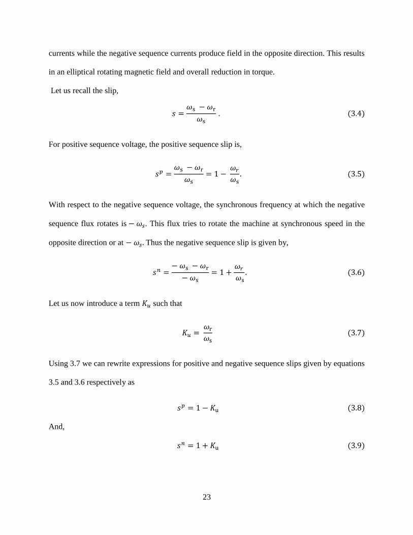
Let us recall the slip,
For positive sequence voltage, the positive sequence slip is,
With respect to the negative sequence voltage, the synchronous frequency at which the negative
sequence flux rotates is . This flux tries to rotate the machine at synchronous speed in the
opposite direction or at Thus the negative sequence slip is given by,
Let us now introduce a term such that
Using 3.7 we can rewrite expressions for positive and negative sequence slips given by equations
3.5 and 3.6 respectively as
And,

24
The advantage of using is that the response of the machine can now be studied based on one
variable instead of the two slips. The impact of asymmetry on the machine is discussed below.
3.6.1 Torque
From the equivalent circuit of the machine shown in Figure2.4 in chapter 2, the square of the
rms of rotor current can be approximated as:
(
)
The air gap power can be written as
Or,
Using 3.10 above, 3.12 can be rewritten as
{ (
)
}
All the variables we are using to represent the rotor quantities are referred to the primary side.
Thus for the simplicity of expressions
and by and respectively. 3.13 can be re
written as
{ (
)
}
Formula 3.13a is valid when machine is supplied with symmetrical voltages. In case of
asymmetrical voltages when the voltage is separated into positive and negative sequence
25
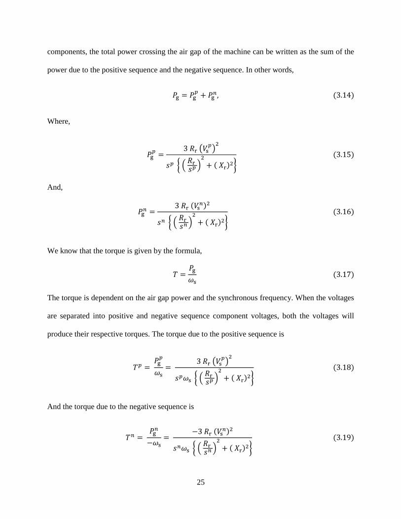
components, the total power crossing the air gap of the machine can be written as the sum of the
power due to the positive sequence and the negative sequence. In other words,
Where,
( )
{ ( )
}
And,
{ ( )
}
We know that the torque is given by the formula,
The torque is dependent on the air gap power and the synchronous frequency. When the voltages
are separated into positive and negative sequence component voltages, both the voltages will
produce their respective torques. The torque due to the positive sequence is
( )
{ ( )
}
And the torque due to the negative sequence is
{ ( )
}
26
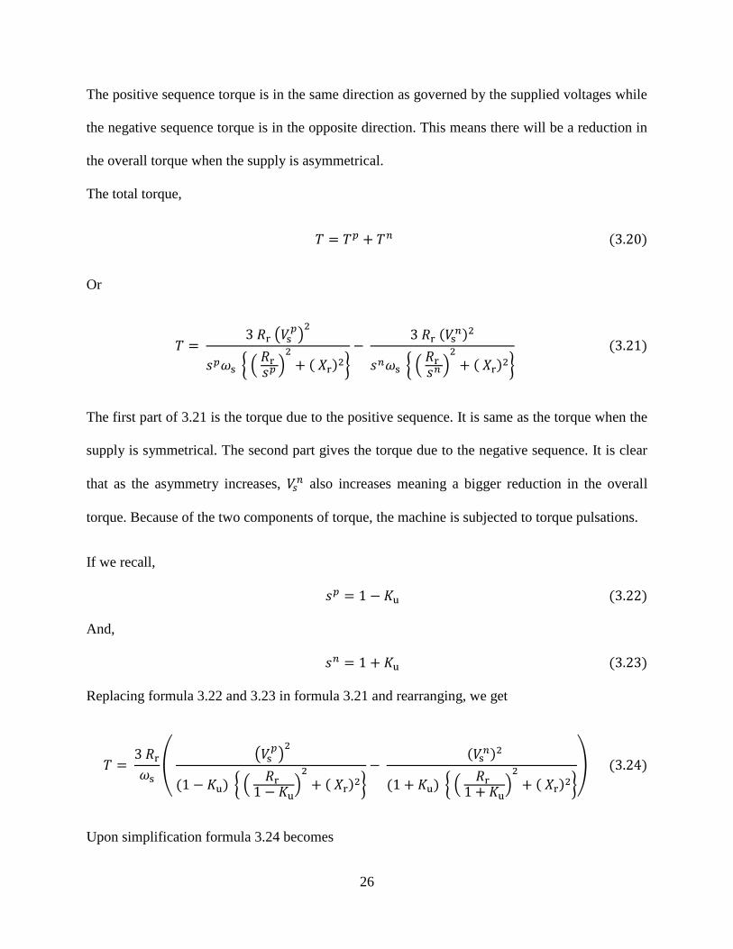
The positive sequence torque is in the same direction as governed by the supplied voltages while
the negative sequence torque is in the opposite direction. This means there will be a reduction in
the overall torque when the supply is asymmetrical.
The total torque,
Or
(
)
{ ( )
}
{ ( )
}
The first part of 3.21 is the torque due to the positive sequence. It is same as the torque when the
supply is symmetrical. The second part gives the torque due to the negative sequence. It is clear
that as the asymmetry increases, also increases meaning a bigger reduction in the overall
torque. Because of the two components of torque, the machine is subjected to torque pulsations.
If we recall,
And,
Replacing formula 3.22 and 3.23 in formula 3.21 and rearranging, we get
(
( )
{ (
)
}
{ (
)
}
)
Upon simplification formula 3.24 becomes

27
( (
)
)
If we recall at a motor start, meaning . If we replace in 3.25
( (
)
)
Recalling machine theory, the starting torque when the supply is symmetrical is given by
Comparing formula 3.26 with 3.27, it is evident that the first part of 3.26 which is the torque due
to positive sequence is similar to torque in 3.27. The second part of 3.26 is introduced due to
asymmetry. Since this part is negative; it means that there is reduction in the starting torque
produced by the machine. Also, it is evident that the negative component increases with
increases in asymmetry because it has present in the numerator. Thus, if the supply
voltage is asymmetrical, there is reduction in the starting torque that is produced by the machine.
3.6.2 Rotor Currents
The square of the rms of rotor current can be approximated as:
(
)
If we consider the positive and negative sequence currents, then we will have
( )
( )
(
)

28
And,
(
)
Referring to the rotor current for the positive sequence given by 3.29, value of is in the range
of .02 during normal operation. This makes (
) much greater than . Since and are in
the same range, the denominator can be approximated by . This high impedance limits
the rotor current. For the same reason, since the positive sequence slip is 1 at the start, the
machine draws high starting current.
Referring to 3.30, the equivalent rotor resistance is (
) . But is close to 2 during
normal operation. Thus the equivalent negative sequence rotor resistance (
) is . The
denominator is thus approximately equal to . This is much smaller compared to the
positive sequence equivalent rotor impedance. Thus even a small negative sequence voltage will
also cause a high amount of negative sequence current to flow in the rotor. We can also look at
this from the locked rotor operation of induction machines. The negative sequence current is
always high because the machine always draws starting current from the point of view of the
negative sequence voltage.
Using and in formula 3.29 and 3.30 above, we get
( )
( )
(
)
And,
(
)

29
Taking the ratio of negative and positive sequence rotor currents, we get
( )
(
)
(
)
(
)
The ratio of the two currents given by 3.33 is dependent on the degree of asymmetry given by
the ratio (
)
However; it is also dependent on which relates to positive and negative
sequence slips. The negative and positive sequence slips are dependent on torques and the
equations governing them are very complex. Thus, the exact correlation between the ratios of
rotor currents to percent unbalance can only be calculated using simulation when other
parameters are known. This is presented in the fifth chapter.
3.6.3 Losses
In the preceding sections it was shown how the overall torque is reduced when machine is
subjected to asymmetrical voltage supply. This is because the negative sequence torque is in the
opposite direction of the positive sequence torque. In order to produce the required torque to
balance the load torque, the machine has to produce extra positive sequence torque. For the same
supply voltage, this will mean an increment in the rotor current and the operating slip.
If we recall machine theory, the losses in the motor mainly occur in the rotor and the
stator circuit. Since the losses in the stator circuit are small compared to those in the rotor circuit,
they are ignored in calculations. The losses can be related to the air gap power as
For the positive sequence circuits,
( )
{ ( )
}

30
Since the positive sequence torque is responsible for producing the torque to balance the load
torque and the negative sequence torque, it has to increase when there is asymmetrical supply.
And since the torque is related to the slip, the slip also increases. Thus, more the asymmetry
more will be the losses in the positive sequence circuit.
The losses in the rotor circuit can also be related to the rotor current as
For positive sequence rotor current,
( )
So it follows that when the rotor currents are increased in order to produce a higher torque, there
is increment in the rotor current. This leads to increased losses as given by 3.37.
Losses occurring in the positive sequence circuit were discussed above. The losses
occurring in the negative sequence circuit are much higher. If we recall, the negative sequence
component cannot contribute to energy delivery in the positive direction. So the negative
sequence power crossing the air gap totally contributes to the losses. Thus the total losses
occurring in the negative sequence circuit is given by:
{ ( )
}
Combining 3.35 and 3.38, the total losses occurring in the machine is given by
(
)
{ ( )
}
{ ( )
}
It is clear from 3.39 that asymmetry increases the losses in the machine. The exact correlation of
losses and asymmetry can only be found when the positive and negative sequence slips are

31
found. According to [7], 6.35 percent asymmetry increases the losses by 50 percent. It is
mentioned that the percent increase in temperature rise is approximately two times the increment
in percent asymmetry. When there is increment in losses due to asymmetry, it tends to increase
the temperature of the machine. As a result, the resistance of the windings is also increased
because of the temperature resulting in a further increment in the losses. Eventually equilibrium
is reached at a higher temperature. Details of this can be found in Ref [8]. The correlation
between percent asymmetry and machine losses, obtained through simulation is presented in the
fifth chapter of this thesis.
3.6.4 Efficiency
When supplied with asymmetrical voltages, the losses in the machine are increased and this leads
to the reduction of efficiency. Mathematically, efficiency is given by the formula
In case of an induction machine, the total output power can be found by subtracting the
losses from the input power. The total input power is the power crossing the air gap. It is the sum
of the positive and negative sequence air gap powers, viz.
The losses occurring in the positive sequence circuit are given by:
Likewise, based on the previous section, the losses occurring in the negative sequence circuit are
given by:
Thus the total losses occurring in the machine is given by

32
If we recall machine theory, the total output power of the machine can be calculated by
subtracting the losses from the input power. Thus,
Or,
(
)
Thus, the output power produced by the machine is
The efficiency of the machine can be calculated as:
Replacing 3.15 and 3.16 in 3.48 we get,
(
( )
{ ( )
}
( (
)
{ ( )
}
) (
{ ( )
}
)
)
Or,
(
( )
{ ( )
}
( (
)
{ ( )
}
) (
{ ( )
}
)
)

33
Therefore,
((
)
{ (
)
}
{ ( )
}
)
It is clear from 3.51 that when asymmetry is zero, the efficiency reduces to , which is
the standard efficiency for induction machines supplied with symmetrical voltages. Asymmetry
reduces the efficiency in two ways. First is by reducing the numerator. When supply voltage is
asymmetrical, there is reduction in the speed of the machine to meet the load requirements. Thus
the slip increases and the term in the numerator of 3.51 reduces. Second, as the level of
asymmetry increases, the denominator of 3.51 also increases thereby causing the efficiency to
reduce. The exact correlation between asymmetry and efficiency is shown in chapter 5.
3.6.5 Life expectancy and de-rating of machines
Heat dissipation in the machine increases with the losses. A machine is designed to withstand
certain temperature and the insulation is also designed accordingly. When there is temperature
rise over the design limit, the insulation of the machine will be damaged over time and the
machine will eventually break down. Thus the life expectation of machine is also negatively
affected when supplied with asymmetrical voltages. This issue studied in reference [11].
To address this problem, higher class of insulation has to be used. Likewise, since
efficiency is related to output power, to get the same output power, a higher input power is
needed when the efficiency is low. In other words, a bigger size of machine is needed to do equal
amount of work. This means machines have to be de-rated which increases the costs. De-rating
of machines is studied more thoroughly in Ref [10].

34
CHAPTER 4: OPERATION OF INDUCTION MACHINES UNDER DISTORTED
SUPPLY VOLTAGE
4.1 Introduction
Voltages and currents in the power system are usually distorted. An ideal supply voltage is
supposed to be symmetrical and sinusoidal. If it deviates from that, then the supply quality is said
to have been degraded. In such situations, the theory of induction machines presented in chapter
2 becomes invalid. The theory of an induction machine operating under nonsinusoidal supply
voltages is presented in this chapter. It is assumed that the supply voltages are symmetrical.
Our focus is on the distortion of voltages and currents in the power system. In the ideal
case these can be represented as sinusoidal quantities. Thus the scope of our definitions will be
limited to distortion of sinusoidal quantities. For the same reason, the words distorted and
nonsinusoidal are often described for sinusoidal quantities when used in the power system. For
the rest of the thesis, distortion will refer to distortion of sinusoidal quantities.
4.2 Types and causes of voltage and current distortion
In the general sense, waveform distortion could be caused by the supply, by the load or by both
of them. When the current is distorted due to the harmonics generated in the load, it is referred to
as distortion due the deterioration of the loading quality. Likewise, when a distortion is caused
by the supply, then the supply quality is said to have been deteriorated. Just like how
asymmetrical voltages and asymmetrical currents are interrelated, voltage and current distortion
are also intertwined. Voltage distortion leads to current distortion and vice versa. Therefore when
studying the impacts of voltage distortion on induction machines, it is an imperative that the
impacts of current distortion also be included in the analysis. The causes of voltage and current
distortion are briefly described in this section.

35
4.2.1 Distortions originating at the generation level
Windings in synchronous generators are not distributed evenly. This can lead to generation of
nonsinusoidal voltage. However, generators are designed to mitigate this problem as much as
possible. As a result, voltage distortion caused by synchronous generators is well below .5% and
can be neglected. The case is different when the source of energy is wind generators. These are
normally connected to the power system via variable frequency converters and power electronic
interfaces which do not produce perfectly sinusoidal voltages. As a result, voltages provided by
wind generators are more distorted than the voltage produced by synchronous generators.
4.2.2 Interaction of voltage and current distortion
When the current is distorted, it causes nonsinusoidal voltage drop on the system impedance.
This in turn causes distortion of the system voltage. This means that even when the supply
quality is ideal, distorted current caused by the load generated harmonics causes nonsinusoidal
voltage drop in the power system, eventually leading to voltage distortion. Moreover, the supply
voltage distortion can distort the load current, which in turn increases the voltage distortion. Thus
there is a feedback that increases both current and voltage distortion.
Similarly, high amount of current distortion can result from a harmonic resonance in the
power system. The power system impedance is mostly inductive. Therefore, capacitors that are
used in the circuit for compensation can resonate with the system impedance. Even the
capacitance of lines can contribute to this phenomenon when the length of the line is comparable
to a quarter of the wavelength of the harmonic. This means that a small distortion in the supply
voltage might lead to harmonic content amplification in the voltage and current.

36
4.2.3 Nonlinear loads
Some loads in the power system are nonlinear by nature. Components of power electronics
devices, like diodes and thyristors, are nonlinear devices. They can draw highly distorted current
and cause current distortion. Fluorescent lamps also lead to current distortion. A major source of
harmonics in some areas are arc furnaces as they draw extremely high amount of distorted
currents. Any load that causes current distortion is generally known as a Harmonic Generating
Load (HGL).
4.3 Mathematical representation of a distorted quantity
Distortion of periodic quantities can be regarded as a superimposition of higher order harmonics
on the fundamental component. Figure 4.1 shows a distorted quantity, where the fundamental
component is superimposed by the 7th
order harmonic. The fundamental component is the
dominating component and has the same frequency as the resulting quantity. The 7th
order
harmonic component shown is 4.1 has angular frequency seven times higher than the
fundamental frequency. It is evident that the harmonic component does not affect the frequency
of the resultant quantity.
Figure 4.1: Representation of a distorted quantity as the sum of two sinusoidal quantities
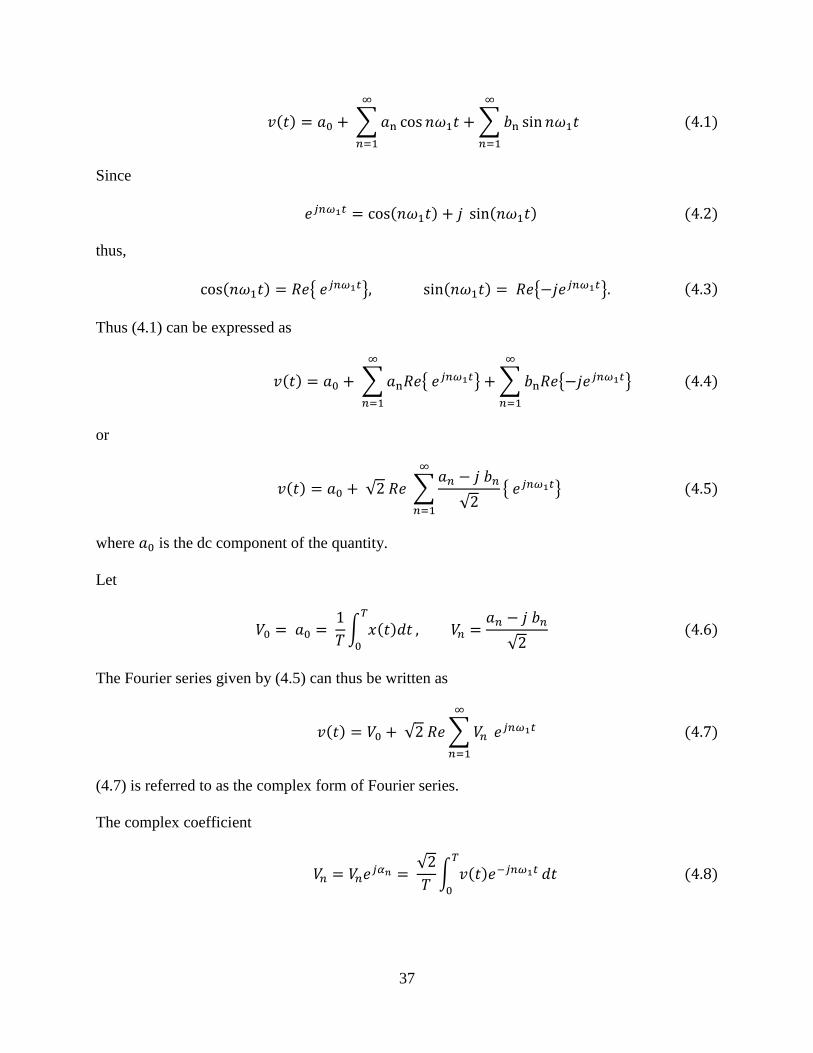
When a sinusoidal quantity is distorted, it is convenient to describe it using a Fourier
series, namely
37
∑
∑
Since
thus,
{ } { }
Thus (4.1) can be expressed as
∑ { }
∑ { }
or
√ ∑
√
{ }
where is the dc component of the quantity.
Let
∫
√
The Fourier series given by (4.5) can thus be written as
√ ∑
(4.7) is referred to as the complex form of Fourier series.
The complex coefficient
√
∫
38
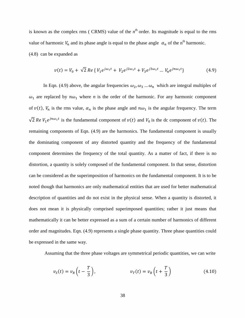
is known as the complex rms ( CRMS) value of the nth
order. Its magnitude is equal to the rms
value of harmonic and its phase angle is equal to the phase angle of the nth
harmonic.
(4.8) can be expanded as
√
In Eqn. (4.9) above, the angular frequencies which are integral multiples of
are replaced by where n is the order of the harmonic. For any harmonic component
of , is the rms value, is the phase angle and is the angular frequency. The term
√ is the fundamental component of and is the dc component of . The
remaining components of Eqn. (4.9) are the harmonics. The fundamental component is usually
the dominating component of any distorted quantity and the frequency of the fundamental
component determines the frequency of the total quantity. As a matter of fact, if there is no
distortion, a quantity is solely composed of the fundamental component. In that sense, distortion
can be considered as the superimposition of harmonics on the fundamental component. It is to be
noted though that harmonics are only mathematical entities that are used for better mathematical
description of quantities and do not exist in the physical sense. When a quantity is distorted, it
does not mean it is physically comprised superimposed quantities; rather it just means that
mathematically it can be better expressed as a sum of a certain number of harmonics of different
order and magnitudes. Eqn. (4.9) represents a single phase quantity. Three phase quantities could
be expressed in the same way.
Assuming that the three phase voltages are symmetrical periodic quantities, we can write
(
) (
)

39
Using the shifting property of harmonics discussed in Ref [15], the CRMS of voltage of the
nth
harmonic can be written as
Since
{
Thus,
{
Similarly the CRMS of nth
harmonic of can be written as
Since
{
Thus,

40
{
Using Eqns. (4.12) and (4.14) that voltage harmonics for the order of 3k +1 can be expressed as
√ [
] √ [
]
The voltage harmonics for the order of 3k and 3k-1 can be calculated similarly. The total voltage
can thus be expressed as
{
√ [
]
√ [ ]
√ [
]
We can conclude from (4.16) that the harmonics of the order 3k+1 are of the positive sequence,
those of order 3k are of the zero sequence, while the harmonics of order 3k -1 are of the negative
sequence. Since we are analyzing a machine which is supplied from three wires with
symmetrical voltages, zero sequence components are absent. Thus, the total voltage
∑ ∑
Using similar analysis the expression for distorted current can be presented as
√ ∑

41
4.4 Measures of voltage and current distortion
The most widely accepted and commonly used measure of distortion is the Total Harmonic
Distortion (THD). It is calculated by comparing the RMS of the harmonic contents to the RMS
of the fundamental.
‖ ‖
‖ ‖
Since the harmonics of different order are orthogonal to each other, the RMS of the distorted
component of voltage can be calculated as
‖ ‖ √
√∑
where are the values of the voltage harmonics. If is the RMS of the fundamental
component of the voltage, then the THD for voltage is given by
√∑
The THD for current can be similarly calculated as
√∑
4.5 Limitations of the single phase equivalent circuit of induction machines
It was discussed in the previous chapter why the single phase equivalent circuit of induction
machine presented in chapter 2 (Figure 4.2) is inadequate to represent a machine when the
supply voltage is asymmetrical. A similar situation will occur when the supply voltage is

42
nonsinusoidal. The single phase equivalent circuit of induction machine as presented in chapter 2
is shown in Figure 4.2.
Figure 4.2: Single phase equivalent circuit of induction machine for sinusoidal symmetrical
supply voltages
When the source voltage is sinusoidal, the supply voltage is composed of only the
fundamental component. Figure 4.2 is sufficient for analysis of the motor properties. When the
supply voltage is distorted, the supply voltage harmonics produce harmonic currents and torque.
Total current response is the sum of the harmonic currents and the fundamental current.
Likewise, the total torque is found my adding the torques produced by the fundamental and the
harmonics.
4.6 Equivalent circuit of the machine under symmetrical distorted supply voltage
Harmonics in the power system can be of positive, zero and negative sequence. For the scope of
our study, we are focusing on a machine supplied with symmetrical three phase voltages, fed
from a three wire system without a neutral. So the zero sequence components do not exist in the
supply voltage. Thus we do not need to consider harmonics of the order that are the integral
multiples of 3. Similarly the even order harmonics contribute much less to the overall distortion
than odd order harmonics. Consequently, they can be ignored from practical considerations. The
dominating harmonics in the power system are 5th
and 7th
order harmonics. The 5th
order

43
harmonic is negative sequence while the 7th
order harmonic is positive sequence. If we study
these two harmonics, we can have an idea of how a machine responds to a distorted supply
voltage.
Figure 4.3: Single phase equivalent circuit of induction machine for the fundament component
Figure 4.4: Single phase equivalent circuit of induction machine for the fifth harmonic
component
Figure 4.5: Single phase equivalent circuit of induction machine for the seventh harmonic
component

44
Figure 4.3 shows the equivalent circuit of a machine for the fundamental frequency. Figure
4.4 shows the equivalent circuit for the 5th
order harmonics while Figure 4.5 represents the same
for the 7th
order harmonic. One can observe that the supply voltage and the equivalent rotor
resistance vary for different harmonic order. Since the inductive reactance are dependent on the
supply frequency, reactance and change for the n
th order harmonic to
and
respectively. The stator winding resistance is independent of supply frequency assuming
that the skin effect is negligible. However the stator core equivalent magnetic resistance depends
on the harmonic order because the power loss in the core changes with frequency. Note that the
stator side voltage is only shown for phase A in all the cases. Assuming that the supply voltage is
symmetrical, one phase of the machine is sufficient in representing all three phases.
It is to be noted that the skin effects on the rotor conductors are ignored during the analysis
presented in this thesis. Skin effects can potentially become significant as the frequency of the
rotor currents increases. To find the change in the resistance due to the skin effect, the exact
dimensions, size and specification of the motor is required. It is hard to study the effects without
knowing the exact geometry of the machine. Since the analysis presented in this thesis is done
for the general sense, it becomes hard to incorporate skin effects into the analysis.
4.7 Analysis of machine performance under distorted supply voltage
Analysis of the machine will be confined to only the 5th
and 7th
order harmonics in addition to
the fundamental component. These are the two most dominant harmonics in the power system.
When effects of these two harmonics are analyzed, other harmonics can be analyzed in a similar
way.
The 5th
order harmonic produces a rotating field that rotates five times as fast as the rotor
but in the opposite direction. On the other hand, the 7th
order harmonic produces a rotating field

45
that rotates seven times as fast as the fundamental in the same direction. In both cases, the
relative angular frequency of the rotating field is six times the synchronous frequency of the
fundamental. Both of them try to rotate the machine at their respective synchronous speeds.
Based on the level of distortion, they draw currents at their respective frequencies and this
current leads to losses and changes in torque among others.
Let us recall the slip,
The slip of the fundamental component is,
where is angular frequency of the fundamental component. Similarly, the frequency at which
the rotating field produced by the fifth harmonic component rotates is Thus the slip for
the 5th
harmonic component is
Likewise the frequency at which the rotating field produced by the seventh harmonic component
rotates is . The slip for the 7th
harmonic component is given by,
Let us now introduce a term such that

46
Using Eqn. (4.27) we can rewrite expressions for the slips given in Eqns. (4.24) to (4.26) as
and,
The advantage of using is that the response of the machine can now be studied based on one
variable. The impact of distortion on the machine performance is discussed below.
4.7.1 Torque
The square of the magnitude of rotor current can be approximated from the equivalent circuit of
the machine shown in Figure 4.2 as:
(
)
The current and impedance in Eqn. (4.31) are rotor quantities referred to the stator side, while the
voltage is on the stator side. For the sake of simplicity, we will replace the quantities
and with and respectively. Eqn. (4.31) can be rewritten as:
(
)
Referring to Chapter 2, the air gap power is given by
{ ( )
}

47
Eqn. (4.33) is valid when machine is supplied with sinusoidal voltages. When the voltage is
distorted and separate circuit are analyzed for the individual harmonics, the total power crossing
the air gap is due to the contribution of all the harmonics. Thus the total air gap power is:
Since we are only dealing with air gap active power in our analysis; the air gap power can be
represented by without causing any ambiguity. Thus,
where,
{ (
)
}
Similarly,
{ (
)
}
and,
{ (
)
}
The torque is given by the formula,
Torque is dependent on the air gap power and the synchronous frequency at which the field
produced by the voltage rotates. When the supply voltage contains 5th
and 7th
order harmonics in
addition to the fundamental quantity, it transfers energy through the air gap as given by Eqns.

48
(4.36) to (4.38) above. All three air gap powers produce their respective torques. The total torque
produced by the machine can be found by adding the torques together. The torque due to the
fundamental component of voltage is:
{ (
)
}
Torque due to the 5th
harmonic component of voltage is:
{ (
)
}
Torque due to the 7th
harmonic component of voltage is:
{ (
)
}
Torque produced by the fundamental component is oriented in the direction as governed by the
supply voltages. The 5th
order harmonic is a negative sequence component and produces a torque
in the opposite direction as the one produced by the fundamental component. The 7th
order
harmonic component is a positive sequence harmonic and produces torque oriented in the same
direction as the fundamental component. The total torque is calculated by adding the individual
torques together because the machine can be considered as a linear device. The total torque T is
or

49
{ (
)
}
{ (
)
}
{ (
)
}
The first part of Eqn. (4.44) is the torque produced by the fundamental component. If the supply
voltages were sinusoidal, voltage would contain only the fundamental component and all the
torque would be produced by the fundamental quantity. However, there is production of torque
due to the 5th
and 7th
harmonic components and the total torque will change. The total torque
might be increased or decreased depending upon the values of the torques due to the 5th
and 7th
order harmonic. It might seem from Eqn. (4.44) that positive sequence harmonics have a positive
impact on the machine due to the addition in torque. However, the addition in torque is minimal
compared to the losses and efficiency reduction it causes. Even the positive sequence harmonics
are harmful to the machine.
Using Eqns. (4.40) to (4.42) above, Eqn. (4.44) can be rewritten as
{ (
)
}
(
){ (
)
}
(
) { (
)
}
The exact value of torque for a certain level of distortion can be calculated using simulation only
when the load torque is given. The results of simulation are presented in the fifth chapter.

50
At a motor start, or . Starting torque is calculated using these values, namely
(
)
From machine theory, the starting torque produced by a machine when supplied with sinusoidal
voltages is given by
Comparing Eqns. (4.46) and (4.47), it is evident that the first part of Eqn. (4.46) which is the
torque due to the fundamental component is the same as the torque in Eqn. (4.47). The second
and the third parts of Eqn. (4.46) are introduced due to distortion. The 5th
order harmonic tends
to reduce the starting torque while the 7th
order harmonic tends to contribute to the starting
torque. Thus the overall starting torque may be increased or decreased depending on the values
of the torques produced by the 5th
and 7th
harmonics.
4.7.2 Rotor Currents
Referring to Eqn. (4.32) above, the square of the rms of rotor current was approximated as:
(
)
The current rms value of the fundamental current is
(
)
Current rms value of the 5th
order harmonic is

51
(
)
and current rms value of the 7th
order harmonic is
(
)
Eqn. (4.48) shows that the current is dependent on the stator voltage and rotor impedances. For
induction machines, equivalent rotor resistance and inductance are approximately of the same
range. For normal operation, Eqn. (4.48) can be roughly approximated as
(
)
Also, during normal operation the slip is in the range of 0.02. Thus the term (
)
becomes much
greater than the term and Eqn. (4.52) can be approximated as
When the motor starts, the slip is 1 and the rotor current rms value is approximated as
and therefore the machine draws high current at the start.
During normal operation, slips for the 5th
and 7th
harmonics can be approximated as and 0
respectively. Using these values in Eqns. (4.50) and (4.51) and simplifying shows that both 5th
and 7th
harmonic voltages draw currents in the range of starting current rms value given by Eqn.
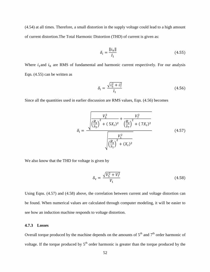
52
(4.54) at all times. Therefore, a small distortion in the supply voltage could lead to a high amount
of current distortion.The Total Harmonic Distortion (THD) of current is given as:
‖ ‖
Where and are RMS of fundamental and harmonic current respectively. For our analysis
Eqn. (4.55) can be written as
√
Since all the quantities used in earlier discussion are RMS values, Eqn. (4.56) becomes
√
(
)
(
)
√
(
)
We also know that the THD for voltage is given by
√
Using Eqns. (4.57) and (4.58) above, the correlation between current and voltage distortion can
be found. When numerical values are calculated through computer modeling, it will be easier to
see how an induction machine responds to voltage distortion.
4.7.3 Losses
Overall torque produced by the machine depends on the amounts of 5th
and 7th
order harmonic of
voltage. If the torque produced by 5th
order harmonic is greater than the torque produced by the

53
7th
order harmonic, the overall torque will be reduced. To produce the required torque in order to
meet the load requirement, the fundamental component has to produce higher torque. This is
only possible through increment in the slip which increases the losses. If the torque produced by
the 7th
harmonic is greater than the torque by the 5th
order harmonic, there isn’t any increment in
losses due to reduction of speed. However, the 7th
order harmonic increases the losses in the
rotor circuit due to the increment in rotor current.
Ignoring the losses in the stator circuit, the losses in the induction machine can be
approximated as
The loss due to the fundamental component of current is:
{ (
)
}
Similarly, the losses occurring due to the 7th
order harmonic of current is:
{ (
)
}
Since the 5th
order harmonic is a negative sequence component, all of the energy transferred
through the air gap by this component goes to losses. Thus,
{ (
)
}
Total losses occurring in the machine can be found by adding the losses given in Eqns. (4.60) to
(4.61) above, namely
or,

54
{ (
)
}
{ (
)
}
{ (
)
}
Eqn. (4.64) shows how voltage distortion leads to increased losses in the induction machines.
Losses can be calculated when the value of slips at a certain load torque are known. This is
presented in Chapter 5 of this thesis. The losses occurring in the induction machine due to
distorted supply voltage, are studied more thoroughly in Refs. [12] and [13].
4.7.4 Efficiency
The output power of induction machine can be found by subtracting the losses from the input
power. The total input power is the power crossing the air gap. Thus,
The losses occurring due to fundamental component is
The output power produced by the fundamental component is . Similarly,
output produced by the 7th
order harmonic component is . Since all the energy
transferred through the air gap by the 5th
order harmonic goes to losses, it does not contribute to
output power. The total output power produced by the machine is given by
The efficiency of the machine can be calculated as:
Since the slip is in the range of .8, maximum portion of power produced by the 7th
order
harmonic goes to losses and only a small part of the power actually contributes to useful energy.
55
In addition to that, all of the power produced by 5th
order harmonic goes to losses. Therefore, if
the supply voltage is distorted, it reduces the efficiency of induction machines.
Substituting the expressions for input and output powers in in Eqn. (4.68) and simplifying yields,
{ (
)
}
{ (
)
}
{ (
)
}
{ (
)
}
{ (
)
}
Eqn. (4.69) gives the efficiency of an induction machine when supplied with a voltage containing
5th
and 7th
order harmonics in addition to the fundamental component. The results of simulation
showing the effects of distortion on efficiency are presented in the fifth chapter.
4.7.5 Life expectancy and de-rating of machines
The impacts of increased losses on life expectancy and de rating of induction machines was
presented in the previous chapter. Both the supply voltage asymmetry and distortion increase the
losses and lead to temperature rise in the machines. In this regard, both have similar impact on
induction machine. Since machines are designed to work under a certain temperature range,
increment of temperature causes damage to insulation and eventually causes failure. Higher
rating insulation has to be used to withstand the extra temperature rise. The size of machines also
needs to be increased to produce the required output power under reduced efficiency. Thus
machines have to be de rated to avoid the risk of untimely failures.
56
CHAPTER 5: COMPUTER MODELLING AND RESULTS
5.1 Introduction
It was discussed in the previous chapters how asymmetry and distortion in the supply voltage
affects the operation of induction machines. The equations that relate its performance to supply
voltage asymmetry and distortion were also developed. The essence of any theory is to provide
the fundamentals of the pertaining subject matter. In many cases, it is difficult to solve equations
analytically. Computer simulation can be used to solve those equations and to verify the
predictions made in theory. This chapter presents the results obtained from simulation of
induction machine model with MATLAB.
The analysis presented in the previous chapters was done assuming that the losses in the
stator circuit were negligible. For analytical purposes it is reasonable to do so as this reduces the
complexity of equations. However, simulation can be applied to the complete model of the
machine since the computer can handle complex equations. Thus, the complete model of
induction machine is used for simulation. The results thus obtained are more accurate.
First part of this chapter presents the verification of a model of induction machine written in
MATLAB. Results are compared with examples presented in Ref. [15]. The response of the
verified model for asymmetrical and distorted supply voltages are presented in the second and
the third part of this chapter respectively. Simulation is done at various levels of asymmetry and
distortion for a single design class of machine.
The simulations were carried out without considering the skin effects. The change in the
rotor resistance with frequency is dependent on various factors like machine size, geometry and
specifications. It is very difficult to generalize it.

57
5.2 Modeling of induction machine under sinusoidal symmetrical supply voltage
A MATLAB m-file code was written for the simulation of a 3 phase 6 pole 60 Hz 7.5 KW Y
connected 208 Volts (L-L) induction machine with the parameter values as given below in /
phase referred to the stator side:
The machine used in this example belongs to CLASS B as per the NEMA MG-1 Standard for
machines and generators design parameters. Appendix 1 presents the characteristics of induction
machine of various classes. The given model was selected because it is the most commonly used
machine for general purpose applications.
The torque slip plot of the machine is given in Figure 5.1.
Figure 5.1: Torque-Slip plot of induction machine at symmetrical sinusoidal voltage

58
The starting torque produced by the machine is 69.3 Nm and the maximum torque is 155 Nm.
When a load of 62 Nm is connected to the machine, it operates at a slip of .03 with 89%
efficiency. The synchronous speed in RPM is 1200. The results obtained from simulation were
verified by comparing to Example 6.2 in Ref [15].
5.3 Modeling of induction machine under asymmetrical sinusoidal supply voltage
The model of the machine given in section 5.2 above was tested with asymmetrical supply
voltages. The results of simulations are presented in this section. The machine was supplied with
voltage source with VUF ranging from 0 to 10 percent in steps of 1%. Phase A of supply voltage
was set to 120 volts at 0 degrees and the remaining two phases were adjusted to get the required
VUF.
5.3.1 Output torque
The torque-speed (T-S) characteristic of the machine was plotted for various levels of VUF in
the supply voltage. The family of curves as shown in Figure 5.2 was obtained.
Figure 5.2: T-S plot of induction machine at varying levels of VUF

59
Figure 5.2 illustrates that the maximum torque and starting torque are reduced as the level of
asymmetry increases. Fig. 5.3 shows the starting torques produced by the machine at various
levels of VUF in detail.
Figure 5.3: Starting torque at varying VUF
Table 5.1 : Starting and maximum torque at varying VUF
Starting torque produced by the machine at symmetrical supply or 0 % VUF is 69.2 Nm and the
maximum torque is 155.5 Nm. As the level of asymmetry in the supply voltage (VUF) increases,
both starting and maximum torque produced by the machine are decreased. For every 1%
0 1 2 3 4 5 6 7 8 9 10
Starting
Torque(Nm)69.2 68 66.9 65.7 64.6 63.5 62.3 61.3 60.2 59.5 58.2
Torque reduction
(%)N/A 1.734 3.324 5.058 6.647 8.237 9.971 11.4 13 14 15.9
Maximum
Torque(Nm)155.5 153 150.5 147.8 145.4 143 140.5 138 136 134 131.8
Torque reduction
(%)N/A 1.608 3.215 4.952 6.495 8.039 9.646 11.1 12.5 13.8 15.24
VUF ( %)
Starting
Torque
Maximum
Torque

60
increase in VUF there is about a 1.7 % decrease in the starting torque and about 1.6% reduction
in the maximum torque.
The shaded area in Table 5.1 shows the values of starting torque and maximum torques
for a 3 % asymmetry in supply. VUF of 3 % in supply is acceptable according to NEMA
guidelines. Results suggest that both the starting and maximum torque are reduced by
approximately 5% at 3% asymmetry. If the machine is such designed that it is operating in its
optimal rating, then a reduction of 5% can in some cases be critical to whether or not the
machine can meet the demands of the connected load. The machine may not be able to overcome
the starting torque of the load in which case it will fail to start, leading to excess heating of the
machine.
5.3.2 Performance of machine when connected to a load of constant torque
In this section the performance of the machine is analyzed when connected to a load of 62 Nm.
The load torque was kept constant at this value and VUF in the supply voltage was varied. The
results of simulation are presented below.
5.3.2.1 Speed
Table 5.2 shows the speed of operation of the given machine when connected to a load of 62Nm
at varying VUF in the supply voltage.
Table 5.2: Operating speed and slips at varying VUF
0 1 2 3 4 5 6 7 8 9 10
1160 1160 1159 1158 1157 1156 1155 1154 1153 1152 1151
0.033 0.033 0.034 0.035 0.036 0.037 0.038 0.038 0.039 0.040 0.041
1.967 1.967 1.966 1.965 1.964 1.963 1.963 1.962 1.961 1.960 1.959
VUF ( %)
Operating Speed
( RPM)
Positive seq Slip
negative seq slip

61
The operating speed of machine is reduced when the VUF in the supply is increased. The
positive and negative sequence slips are also given in table --. As the speed reduces, the positive
sequence slip increases. When the supply voltage are symmetrical the machine operates at a
positive sequence slip of .033 while when the VUF is 10 %, the slip is .041, with an operating
speed of 1151 RPM. Since the losses and efficiency of machine are directly related to the slip,
results indicate that the losses of the machine will be increased while the efficiency will be
decreased with increase in asymmetry. The operating speed and slips for VUF of 3% are
highlighted. At 3% asymmetry, the speed reduces by 2 RPMs and the slip is increases by .002.
5.3.2.2 Losses
The operating speed of the machine directly correlates to losses. An induction machine consists
of various components each of which can contribute to losses. Losses occurring in each of the
different components of the machine are presented separately.
The detail of losses is presented in Table 5.3. The last column of the table shows the total
losses. The total losses in the machine are increased with increase in VUF.
Table 5.3: Losses occurring in the machine at varying VUF
Due to
pos seq
Due to
neg seqTotal
Due to
pos seq
Due to
neg seqTotal
0 1160 621.4 0.0 621.4 267.4 0.0 267.4 888.8 0.0 888.8
1 1160 610.6 2.0 612.6 262.8 1.0 263.7 873.3 3.0 876.3
2 1159 625.4 7.8 633.2 270.4 3.7 274.0 895.8 11.5 907.2
3 1158 639.4 17.8 657.2 277.6 8.4 286.0 917.0 26.2 943.2
4 1157 654.3 30.2 684.5 285.2 14.3 299.5 939.5 44.5 984.0
5 1156 668.8 46.2 715.0 292.6 21.9 314.5 961.3 68.2 1029.5
6 1155 682.4 66.5 749.0 299.6 31.6 331.1 982.0 98.1 1080.1
7 1154 696.9 88.0 784.9 306.9 41.8 348.7 1003.9 129.8 1133.6
8 1153 711.2 112.5 823.6 314.2 53.4 367.5 1025.3 165.8 1191.2
9 1152 725.1 139.9 865.0 321.2 66.4 387.6 1046.3 206.3 1252.6
10 1151 738.7 170.3 909.1 328.2 80.9 409.0 1066.9 251.2 1318.1
Ohmic losses in rotor
winding (W)Total
Losses
(W)
VUF
( % )
Speed
( RPM)
Total
loss for
pos
seq(W)
Total
loss for
neg
seq(W)
Ohmic losses in stator
winding (W)

62
Figure 5.4: Plot of the total losses at varying VUF
The total losses occurring in the machine are plotted at varying VUF level in Figure 5.4.
When the supply voltages are symmetrical, the total losses occurring in the machine are around
889 watts. When the VUF is 10%, the total losses are 1.32 kWs. It is also to be noted how the
slope of the figure is increasing with VUF. This suggests that the losses are actually multiplied
with increase in asymmetry.
Table 5.4 : Increment in losses at varying VUF
VUF (%) 0 1 2 3 4 5 6 7 8 9 10
Total losses(W) 888.6 876.3 907.2 943.2 984.0 1029.5 1080.1 1133.6 1191.2 1252.6 1318.1
Increment in total
losses (%)N/A -1.4 2.1 6.1 10.7 15.9 21.6 27.6 34.1 41.0 48.3

63
The increment in the total losses occurring due to increased asymmetry is presented in
Table 5.4. When the asymmetry is 3%, the losses are increased by 6%. This is very alarming
because it means that the machine will have to handle the extra 6% losses all the time. This will
eventually cause the machine to fail. When the asymmetry is 10%, there is 48% increment in the
losses. For asymmetry of 1%, there is reduction in losses. For the given machine at the given
load, the speed of machine remains the same at 1% VUF, while the positive sequence input
voltages are reduced. This means that the same output power is produced at a lower input power.
Since the slip is constant, lower input power leads to reduced losses. This is a very particular
case and it doesn’t represent the general response of machine for 1% asymmetry. Overall, there
is a big increment in the losses when the supply voltages are asymmetrical.
Table 5.5 shows that there is an increment in the losses occurring due to the positive
sequence component as asymmetry increases. This is so because when the negative sequence
power increases, it increases the negative sequence torque. To overcome this torque, more
positive sequence current has to flow in the circuit, leading to increased losses.
Table 5.5: Losses due to the positive sequence at varying VUF
Table 5.3 also shows the losses occurring in the rotor and the stator circuits. As the level
of asymmetry increases, the ohmic losses occurring in the stator circuit are much more than those
in the rotor circuits. Results also suggest that most of the losses due to the negative sequence
component occur in the stator of the machine. When the supply voltage is symmetrical, the stator
VUF (%) 0 1 2 3 4 5 6 7 8 9 10
Losses due to pos
seq(W)888.8 873.3 895.8 917 939.5 961.3 982 1004 1025.3 1046 1067
Increment in pos.
seq losses (%)N/A -1.743 0.783 3.174 5.708 8.159 10.48 12.95 15.358 17.72 20.04

64
losses are 620 watts while at a VUF of 10%, the stator losses are 909 watts. About 170 watts is
due to the negative sequence while about 740 watts are due to the positive sequence.
Results suggest that losses are increased with asymmetry in the supply voltage. Since
the losses are dissipated as heat machine is subjected to excess heat when the supply is
asymmetrical. The results also suggest the ohmic losses occurring in the stator winding of the
machine are also highly increased. There is increased heat dissipation in the stator which can
lead to thermal failure of the machine.
5.3.2.3 Efficiency and power relations
Increased level of asymmetry leads to increased losses. This will lead to a reduction in the
efficiency of the machine. Table 5.6 shows the values of efficiency at various VUF levels while
Figure 5.5 shows the plot of efficiency as a function of VUF.
Table 5.6: Efficiency at varying VUF
Figure 5.5: Plot of efficiency of machine at varying VUF
VUF (%) 0 1 2 3 4 5 6 7 8 9 10
Efficiency(%) 89.7 89.7 89.4 89.0 88.6 88.2 87.7 87.1 86.6 86.0 85.3

65
Table 5.6 shows how the efficiency is reduced with increase in asymmetry. When the
supply voltages are symmetrical the efficiency is 89.7 % while it reduces to 85.3 % when the
VUF is 10%. At 3% asymmetry, the efficiency is reduced to 89% which is only a reduction of .7
percent and therefore is not so alarming. Figure 5.5 shows the plot of efficiency at varying VUF.
The efficiency reduces approximately linearly with VUF.
Although the losses are highly increased with asymmetry, there is approximately a linear
relation between efficiency and asymmetry. This is because the input power of the machine
increases with increased VUF and prevents the efficiency from decreasing rapidly. The
relationship of various powers in the machine is presented in Table 5.7.
Table 5.7: Machine power relations at varying VUF
Table shows how the output power is decreasing with increased VUF. This is because of
the reduced speed. However the positive sequence input power increases with VUF. The positive
sequence air gap is almost constant. This means most of the excess positive sequence power
drawn from the system dissipates in the stator. Table also shows how most of the negative
sequence input power dissipates as ohmic losses in the stator circuit and only a small portion of
VUF
(%)
Pos seq
input
power
(W)
Stator
power
loss for
pos
Pos seq
air gap
power
(W)
Neg seq
input
power
(W)
Stator
power loss
for neg
seq(W)
Neg seq
air gap
power
(W)
Output
Power
(W)
0 8643.7 621.36 8022.3 0.0 0 0.0 7754.9
1 8493.3 610.55 7882.8 2.5 2.0383 0.5 7619.5
2 8538.5 625.39 7913.1 9.6 7.7695 1.9 7640.9
3 8570.6 639.42 7931.2 22.1 17.766 4.3 7649.5
4 8613.2 654.34 7958.8 37.5 30.173 7.3 7666.6
5 8647.5 668.76 7978.7 57.4 46.215 11.2 7675.4
6 8670.7 682.42 7988.3 82.6 66.546 16.1 7673.2
7 8703.8 696.94 8006.8 109.3 88.004 21.3 7679.4
8 8732.1 711.17 8020.9 139.7 112.45 27.2 7680.6
9 8755.8 725.11 8030.7 173.8 139.9 33.9 7677.0
10 8775.1 738.74 8036.3 211.6 170.33 41.3 7668.6

66
the power crosses the air gap. When there is increased asymmetry, negative sequence
components produce torque in the negative direction. Since the machine has to meet the load
requirements, this means that the positive sequence has to produce extra torque. This can either
be achieved through increased voltage or reduced speed. The voltage cannot be increased thus
the speed is reduced. As the speed of the machine is reduced, the losses increases and more
power is lost in the circuit. To fulfill the deficit of power, the machine tries to compensate by
drawing more power from the system which can only be achieved through increased currents.
This further increases the losses. Equilibrium is attained when the excess positive sequence
power crossing the air gap balances the negative sequence air gap power. However, to attain this
extra positive power, the positive sequence current is increased by a great amount which causes a
lot of drop in the stator circuit.
Table 5.8: Power relations in the air gap at varying VUF
Table 5.8 shows the power relations in the air gap of the induction machine when the supply
voltage is asymmetrical. It shows the portions of positive and negative sequence air gap powers
going into mechanical work. The part of negative sequence air gap power going to the shaft to do
mechanical work is shown as negative (Column 5). The slip for the negative sequence is greater
VUF
Pos seq air gap
power (Pg)
(W)
Neg seq air
gap power
(W)
Pos seq mech pow
(Pm1)= (1-s)Pg
(W)
Neg seq mech pow
(Pm2)= (1-s)Pg
(W)
Total mechanical
power (W)
(Pm1+Pm2)
Shaft Power
calcualted from
output torque(W)
0 8022.3 0.0 7754.9 0.0 7754.9 7754.9
1 7882.8 0.5 7620.0 -0.5 7619.5 7619.5
2 7913.1 1.9 7642.7 -1.8 7640.9 7640.9
3 7931.2 4.3 7653.6 -4.1 7649.5 7649.5
4 7958.8 7.3 7673.6 -7.0 7666.6 7666.6
5 7978.7 11.2 7686.2 -10.8 7675.4 7675.4
6 7988.3 16.1 7688.7 -15.5 7673.2 7673.2
7 8006.8 21.3 7699.9 -20.5 7679.4 7679.4
8 8020.9 27.2 7706.8 -26.2 7680.6 7680.6
9 8030.7 33.9 7709.5 -32.5 7677.0 7677.0
10 8036.3 41.3 7708.2 -39.6 7668.6 7668.6

67
than 1 and the term (1-s) is negative. The direction of the torque produced by negative sequence
mechanical power is opposite to the direction of the torque produced by positive sequence. The
portion of the positive air gap power going into mechanical work in the shaft is also given in
Table 5.8. The total mechanical power produced by the machine is the sum of the mechanical
powers produced by the positive and negative sequences. This power almost remains constant
because the machine is connected to a load of constant torque. The total shaft power can also be
calculated using the output torque and motor speed and it is shown in column 7. As the
asymmetry increases, there is also an increment in the losses in the rotor for both positive and
negative sequence. However, this is not as alarming as the losses in the stator circuit.
5.3.2.4 Current response of induction machine
Response of the machine in terms of its output was discussed above. It is equally important to
study the current response of an induction machine when subjected to voltage asymmetry. This
can be achieved by studying the asymmetry in the machine current resulting from the asymmetry
in the supply voltage.
Table 5.9: Currents in the stator and rotor of the machine at varying VUF
VUF(%)
Magnitude
of pos seq
stator
current (A)
Magnitude
of neg seq
stator
current (A)
Magnitude
of pos seq
rotor
current (A)
Magnitude
of neg seq
rotor
current (A)
CUF for
stator (%)
CUF for
rotor (%)
0 26.54 0.00 24.88 0.00 0.00 0.00
1 26.31 1.52 24.66 1.50 5.78 6.07
2 26.63 2.97 25.02 2.92 11.15 11.68
3 26.93 4.49 25.35 4.42 16.67 17.43
4 27.24 5.85 25.69 5.76 21.47 22.41
5 27.54 7.24 26.02 7.13 26.29 27.38
6 27.82 8.69 26.33 8.55 31.23 32.47
7 28.11 9.99 26.66 9.83 35.54 36.89
8 28.40 11.29 26.97 11.12 39.77 41.22
9 28.67 12.59 27.27 12.40 43.92 45.47
10 28.94 13.90 27.56 13.68 48.02 49.64
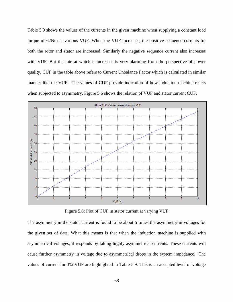
68
Table 5.9 shows the values of the currents in the given machine when supplying a constant load
torque of 62Nm at various VUF. When the VUF increases, the positive sequence currents for
both the rotor and stator are increased. Similarly the negative sequence current also increases
with VUF. But the rate at which it increases is very alarming from the perspective of power
quality. CUF in the table above refers to Current Unbalance Factor which is calculated in similar
manner like the VUF. The values of CUF provide indication of how induction machine reacts
when subjected to asymmetry. Figure 5.6 shows the relation of VUF and stator current CUF.
Figure 5.6: Plot of CUF in stator current at varying VUF
The asymmetry in the stator current is found to be about 5 times the asymmetry in voltages for
the given set of data. What this means is that when the induction machine is supplied with
asymmetrical voltages, it responds by taking highly asymmetrical currents. These currents will
cause further asymmetry in voltage due to asymmetrical drops in the system impedance. The
values of current for 3% VUF are highlighted in Table 5.9. This is an accepted level of voltage

69
asymmetry under NEMA guidelines. The asymmetry in current resulting from 3% VUF is found
to be 17%. Thus there is close to 6 times increment in current asymmetry at the accepted level of
voltage asymmetry. Thus an induction machine can be regarded as an amplifier of current
asymmetry. Although 3% VUF may be considered benign, a CUF of 17% is very harmful to the
power system in various ways.
Overall, the results obtained in this section suggest that voltage asymmetry is very harmful to
the machine from the point of view of losses. Although asymmetry also affects machine torque
and efficiency, the excess heat generated due to the losses is what is more critical. The machine
will get damaged over time due to thermal failures if subjected to voltage asymmetry. To ensure
the safety of machines, either the supply voltage asymmetry needs to be corrected or the machine
size should be increased so that it can incorporate the losses. This means an addition of cost. On
the other hand, induction machine acts like an amplifier of current asymmetry and is very
harmful from the perspective of power quality. Since majority of the load in the power system is
induction motor load; even a small amount of voltage asymmetry in the supply will lead to a
high amount of current asymmetry and finally result in increased voltage asymmetry.
5.4 Modeling of induction machine under symmetrical distorted supply voltages
This section presents the results of the simulation of the same machine supplied with
symmetrical distorted voltages. The THD in supply voltage was varied from 0 to 10 % in steps of
1%. The fundamental component of voltage was kept fixed at 120 V and the THD was varied by
increasing the amount of harmonic content. Since the 5th
and the 7th
order harmonics are of
opposite phase sequence, their effects on the machine were studied separately.

70
5.4.1 Output torque
The output torque of the machine was plotted at various levels of THD for the 5th
and the 7th
order harmonics. Figure 5.7 shows the torques at different THD of 7th
harmonic. The subplot at
the bottom shows the torque produced by the 7th
order harmonic. The subplot on the top is the
total torque for different THD levels. One can observe that in the subplot at the bottom, the
individual curves for various THDs are distinct, while the plots for the total torque are coinciding
one over another. It is so because the torque produced by the seventh harmonic component is so
small that the total torque remains virtually unaffected. Since the seventh order harmonic is a
positive sequence component, the greater the THD, the greater is the positive torque produced.
At 10 % THD the torque produced by seventh harmonic component is approximately .004 Nm.
Figure 5.7: Plot of the torques produced by the fundamental and seventh harmonic component at
varying THD
Figure 5.8 shows the T-S characteristics at various THD levels for the fundamental plus the
seventh harmonic. The individual curves are clustered together. Figure 5.9 and gives the starting

71
torques for various levels of THD for the 7th
order harmonic. The total variation in the overall
starting torque when the THD is varied from 0 to 10 % is only about .004. Likewise, distortion of
voltage doesn’t have any significant impact on the maximum torque produced by the machine.
Figure 5.8: T-S plot at varying THD levels for the seventh harmonic
Figure 5.9: Starting torques at various THD levels for seventh harmonic
T-S plot for various THD levels corresponding to the 5th
harmonic component is shown in Figure
5.10. The 5th
order harmonic is negative sequence and produces torque in the opposite direction

72
of the fundamental component. Just like the previous case, THD in the voltage due the 5th
order
harmonic also doesn’t have any significant impact on the torque in the machine.
Figure 5.10: T-S plot for varying THD for fifth harmonic
The maximum and starting torques for various levels of THD is presented in Table 5.10.
THD in the voltage up to 10% doesn’t have any significant impact on the starting and maximum
torques. Values of torques are highlighted for 3% THD. There is practically no change in the
torques.
Table 5.10: Machine output torques at varying THD levels
0 1 2 3 4 5 6 7 8 9 10
For n = 5 69.3 69.3 69.3 69.3 69.3 69.3 69.3 69.3 69.3 69.2 69.2
For n = 7 69.3 69.3 69.3 69.3 69.3 69.3 69.3 69.3 69.3 69.3 69.3
For n = 5 155.8 155.8 155.8 155.8 155.8 155.8 155.8 155.8 155.8 155.8 155.8
For n = 7 155.8 155.8 155.8 155.8 155.8 155.8 155.8 155.8 155.8 155.8 155.8
Starting
Torque
(Nm)
Maximum
Torque
(Nm)
THD( %)

73
5.4.2 Performance of machine when connected to a load of constant torque
The model of the machine given in 5.2 above was simulated by supplying symmetrical voltages
of various THDs while connected to a load of 62Nm torque. The load torque was kept constant at
this value. The impact of distortion on machine performance is discussed below
5.4.2.1 Speed
The operating speed of the machine at various THD levels of both the 7th
and 5th
order harmonics
is presented in Table 5.11.
Table 5.11: Machine speed and slips at varying THD levels
Table 5.11 shows how the operating speed of the machine remains unchanged for various levels
of THDs for both the 5th
and 7th
order harmonics. This is so because the magnitude of the
fundamental quantity of voltage is kept constant. The fundamental component produces the load
torque required by the machine at all times and the machine doesn’t slow down. This is only
possible because the torques produced by the harmonic components is negligible compared to
the torque produced by the fundamental component.
5.4.2.2 Machine equivalent impedance
Equivalent circuit of the induction machine for distorted supply voltages revealed how the circuit
parameters are dependent on the supply voltage frequency. When the machine is supplying a
0 1 2 3 4 5 6 7 8 9 10
1160 1160 1160 1160 1160 1160 1160 1160 1160 1160 1160
0.03 0.03 0.03 0.03 0.03 0.03 0.03 0.03 0.03 0.03 0.03
1.19 1.19 1.19 1.19 1.19 1.19 1.19 1.19 1.19 1.19 1.19
1160 1160 1160 1160 1160 1160 1160 1160 1160 1160 1160
0.03 0.03 0.03 0.03 0.03 0.03 0.03 0.03 0.03 0.03 0.03
0.86 0.86 0.86 0.86 0.86 0.86 0.86 0.86 0.86 0.86 0.86
n = 7
Operating Speed
( RPM)
Fund. Slip
Harm. Slip
Operating Speed
( RPM)
Fund. Slip
Harm. Slip
THD ( %)
n = 5

74
fixed load at constant speed, the impedance of the machine doesn’t change. We can thus
calculate the overall equivalent impedance offered by the machine.
Table 5.12: Machine equivalent impedance for different harmonics
Table 5.12 shows how the equivalent impedance offered by the machine varies with frequency.
The machine operates at a slip in the range of .03 for the fundamental component, while the slip
is .86 and 1.2 for the seventh and fifth harmonics respectively. Thus the equivalent rotor
resistance is much higher for the fundamental component as compared to the harmonics. This
consequently makes the equivalent resistance of the machine higher for the fundamental
component. However, since the inductive reactance is proportional to the frequency, it increases
with frequency.
5.4.2.3 Current response of induction machine
Table 5.13 presents the magnitudes of stator and rotor currents at various levels of THD for the
5th
harmonic component. As explained earlier, the machine was connected to a load of constant
torque of 62Nm. The magnitude of the fundamental component of voltage was kept constant at
120 V and THD was varied by varying the magnitude of the harmonic component of voltage.
Consequently the fundamental component of current drawn by the machine was also found to be
constant at 26.6 Amperes. This is possible because the torque produced by the harmonic
components is negligible.
Component Machine equivalent impedance (ohms)
Fundamental 4.1 - 1.93i
5th harmonic 0.41 - 3.55i
7th harmonic 0.46 - 4.96i

75
Table 5.13: Machine currents at varying THD levels for fifth harmonic
The magnitude of the 5th
order harmonic current is very small compared to the fundamental
current. The level of distortion in the currents is about 1.3 times the level of the THD in the
supply voltage. This means that the induction machine doesn’t amplify distortion by a great
extent. Rather, it only reflects the distortion present in the supply voltages.
Table 5.14: Currents at varying THD levels for seventh harmonic
Supply
voltage
THD(%)
Magnitude
of fund.
stator
current (A)
Magnitude
of harm.
stator
current (A)
Magnitude
of fund.
rotor
current (A)
Magnitude
of harm.
rotor
current (A)
THD in
stator
current
(%)
THD in
rotor
current
(%)
0 26.54 0.00 24.88 0.00 0.00 0.00
1 26.54 0.34 24.88 0.33 1.27 1.33
2 26.54 0.67 24.88 0.66 2.53 2.66
3 26.54 1.01 24.88 0.99 3.80 3.99
4 26.54 1.35 24.88 1.32 5.07 5.32
5 26.54 1.68 24.88 1.66 6.34 6.65
6 26.54 2.02 24.88 1.99 7.60 7.99
7 26.54 2.35 24.88 2.32 8.87 9.32
8 26.54 2.69 24.88 2.65 10.14 10.65
9 26.54 3.03 24.88 2.98 11.40 11.98
10 26.54 3.36 24.88 3.31 12.67 13.31
For n= 5
Supply
voltage
THD(%)
Magnitude
of fund.
stator
current (A)
Magnitude
of harm.
stator
current (A)
Magnitude
of fund.
rotor
current (A)
Magnitude
of harm.
rotor
current (A)
THD in
stator
current
(%)
THD in
rotor
current
(%)
0 26.54 0.00 24.88 0.00 0.00 0.00
1 26.54 0.24 24.88 0.24 0.91 0.95
2 26.54 0.48 24.88 0.47 1.81 1.91
3 26.54 0.72 24.88 0.71 2.72 2.86
4 26.54 0.96 24.88 0.95 3.63 3.81
5 26.54 1.20 24.88 1.19 4.54 4.76
6 26.54 1.45 24.88 1.42 5.44 5.72
7 26.54 1.69 24.88 1.66 6.35 6.67
8 26.54 1.93 24.88 1.90 7.26 7.62
9 26.54 2.17 24.88 2.13 8.17 8.58
10 26.54 2.41 24.88 2.37 9.07 9.53
For n = 7

76
Table 5.14 shows the currents for various levels of THD of the 7th
order harmonic. Comparing
Table 5.14 with Table 5.13, one can observe that the magnitude of harmonic current is lower for
the 7th
order harmonic as compared to the 5th
harmonic. This is because the impedance for the 7th
harmonic component is higher than the 5th
harmonic. As the order of harmonic increases, the
harmonic currents will also get reduced.
5.4.2.4 Losses
The losses occurring in the machine at various levels of THD in supply voltages is presented in
this section. Results due to the 5th
and 7th
order harmonics are presented separately.
Table 5.15: Losses in the machine at varying THD levels for fifth harmonic
Losses due to the fundamental component are constant. Losses due to the 5th
order harmonic are
increasing with THD. Most of the losses for the harmonic occur in the stator circuit. At 10%
THD, the losses due to the fundamental are 621 watts, while losses due to harmonic are only 10
watts. Table 5.16 shows the overall increment in the losses due to the 5th
harmonic.
Due to
fund.
Due to
harmo.Total
Due to
fund
Due to
harm.Total
0 1160 621.4 0.0 621.4 267.4 0.0 267.4 888.8 0.0 888.8
1 1160 621.4 0.1 621.5 267.4 0.0 267.5 888.8 0.1 888.9
2 1160 621.4 0.4 621.8 267.4 0.2 267.6 888.8 0.6 889.4
3 1160 621.4 0.9 622.3 267.4 0.4 267.8 888.8 1.3 890.1
4 1160 621.4 1.6 623.0 267.4 0.8 268.2 888.8 2.4 891.1
5 1160 621.4 2.5 623.9 267.4 1.2 268.6 888.8 3.7 892.4
6 1160 621.4 3.6 625.0 267.4 1.7 269.1 888.8 5.3 894.1
7 1160 621.4 4.9 626.2 267.4 2.3 269.7 888.8 7.2 896.0
8 1160 621.4 6.4 627.7 267.4 3.0 270.4 888.8 9.4 898.2
9 1160 621.4 8.1 629.4 267.4 3.8 271.2 888.8 11.9 900.7
10 1160 621.4 10.0 631.3 267.4 4.7 272.1 888.8 14.7 903.5
For n = 5
THD
( % )
Speed
( RPM)
Ohmic losses in stator
winding (W)
Ohmic losses in rotor
winding (W)Total
loss for
fund(W)
Total
loss for
harm
(W)
Total
Losses
(W)

77
Table 5.16: Increment in losses for varying THD levels for fifth harmonic
Table 5.17 shows the losses in the machine at various levels of THD due to the 7th
order
harmonic. The losses due the 7th
harmonic are even lesser than the 5th
harmonic.
Table 5.17: Losses in the machine at varying THD levels for seventh harmonic
From the results of simulation, one can conclude that distortion in the supply voltage up to 10%
only increases the losses in the machine by a negligible amount.
5.4.2.5 Efficiency and power relations
Efficiency of the machine at various THD levels for 5th
and 7th
order harmonics is given in Table
5.18. There is practically no change in the efficiency of the machine due to voltage distortion in
the given range.
THD(%) 0 1 2 3 4 5 6 7 8 9 10
Total losses(W) 888.8 888.9 889.4 890.1 891.1 892.4 894.1 896.0 898.2 900.7 903.5
Increment in total
losses (%)N/A 0.0 0.1 0.1 0.3 0.4 0.6 0.8 1.1 1.3 1.7
Due to
fund.
Due to
harmo.Total
Due to
fund
Due to
harm.Total
0 1160 621.4 0.0 621.4 267.4 0.0 267.4 888.8 0.0 888.8
1 1160 621.4 0.1 621.5 267.4 0.0 267.4 888.8 0.1 888.9
2 1160 621.4 0.2 621.6 267.4 0.1 267.5 888.8 0.3 889.1
3 1160 621.4 0.4 621.8 267.4 0.2 267.6 888.8 0.6 889.4
4 1160 621.4 0.8 622.2 267.4 0.4 267.8 888.8 1.2 890.0
5 1160 621.4 1.3 622.7 267.4 0.6 268.0 888.8 1.9 890.7
6 1160 621.4 1.8 623.2 267.4 0.9 268.3 888.8 2.7 891.4
7 1160 621.4 2.5 623.9 267.4 1.2 268.6 888.8 3.7 892.5
8 1160 621.4 3.3 624.7 267.4 1.6 269.0 888.8 4.9 893.6
9 1160 621.4 4.2 625.6 267.4 2.0 269.4 888.8 6.2 894.9
10 1160 621.4 5.1 626.5 267.4 2.4 269.8 888.8 7.5 896.3
For n = 7
Ohmic losses in rotor
winding (W)Total
Losses
(W)
THD
( % )
Speed
( RPM)
Total
loss for
fund(W)
Total
loss for
harm
(W)
Ohmic losses in stator
winding (W)

78
Table 5.18: Efficiency of the machine at varying THD level
Table 5.19: Power relations in the machine at varying THD levels for fifth harmonic
Table 5.19 shows the input, air gap and output power of the machine at various THD levels of 5th
harmonic. The input power, power loss in the stator and the air gap power are constant for the
fundamental component. The input power due to harmonic are increased with the increase in the
THD but its amount is negligible compared to the fundamental. Out of the total input power for
the harmonics, almost 80% is lost in the stator while only about 20% crosses the air gap. This is
because the stator equivalent resistance is higher than the rotor equivalent resistance for the
harmonic component. Table 5.20 shows the same relations of powers corresponding to the 7th
order harmonic. The results are almost the same for the 7th
order harmonic. Majority of the input
power is lost in the stator and only about 20% of the total power crosses the air gap. The main
difference between the two harmonic components is that in case of the 5th
harmonic component,
there is slight reduction in the output power. This is because the 5th
harmonic component
0 1 2 3 4 5 6 7 8 9 10
n=5 89.7 89.7 89.7 89.7 89.7 89.7 89.7 89.7 89.7 89.7 89.6
n=7 89.7 89.7 89.7 89.7 89.7 89.7 89.7 89.6 89.6 89.6 89.6Efficiency(%)
THD (%)
Voltage
THD
(%)
Fund.
input
power (W)
Stator
power loss
for Fund.
(W)
Fund. air
gap power
(W)
Harm.
input
power (W)
Stator power
loss for harm.
(W)
Harm. air
gap power
(W)
Output
Power
(W)
0.0 8643.7 621.4 8022.3 0.0 0.0 0.0 7754.9
1.0 8643.7 621.4 8022.3 0.1 0.1 0.0 7754.9
2.0 8643.7 621.4 8022.3 0.6 0.4 0.2 7754.9
3.0 8643.7 621.4 8022.3 1.3 0.9 0.4 7754.9
4.0 8643.7 621.4 8022.3 2.2 1.6 0.6 7754.8
5.0 8643.7 621.4 8022.3 3.5 2.5 1.0 7754.7
6.0 8643.7 621.4 8022.3 5.0 3.6 1.4 7754.6
7.0 8643.7 621.4 8022.3 6.8 4.9 1.9 7754.5
8.0 8643.7 621.4 8022.3 8.9 6.4 2.5 7754.4
9.0 8643.7 621.4 8022.3 11.3 8.1 3.2 7754.3
10.0 8643.7 621.4 8022.3 13.9 10.0 4.0 7754.2

79
produced torque in the opposite direction as produced by the fundamental. However since the 7th
order harmonic is a positive sequence component, it produced torque in the same direction as the
fundamental and therefore there is a slight increase in the total output power produced by the
machine.
Table 5.20: Power relation in the machine at varying THD levels for seventh harmonic
Table 5.21: Power relations in the air gap at varying THD levels for fifth harmonic
Voltage
THD
(%)
Fund.
input
power
(W)
Stator
power
loss for
Fund. (W)
Fund. air
gap
power
(W)
Harm.
input
power
(W)
Stator
power loss
for harm.
(W)
Harm. air
gap
power
(W)
Output
Power
(W)
0 8643.7 621.4 8022.3 0.0 0.0 0.0 7754.9
1 8643.7 621.4 8022.3 0.1 0.1 0.0 7754.9
2 8643.7 621.4 8022.3 0.3 0.2 0.1 7754.9
3 8643.7 621.4 8022.3 0.7 0.5 0.3 7755.0
4 8643.7 621.4 8022.3 1.3 0.8 0.5 7755.0
5 8643.7 621.4 8022.3 2.0 1.3 0.7 7755.0
6 8643.7 621.4 8022.3 2.9 1.8 1.0 7755.1
7 8643.7 621.4 8022.3 3.9 2.5 1.4 7755.1
8 8643.7 621.4 8022.3 5.1 3.3 1.8 7755.2
9 8643.7 621.4 8022.3 6.4 4.1 2.3 7755.2
10 8643.7 621.4 8022.3 7.9 5.1 2.8 7755.3
Fund. Harm. Fund Harm.
0 8022.3 0.0 7754.9 0.0 7754.9 7754.9
1 8022.3 0.0 7754.9 0.0 7754.9 7754.9
2 8022.3 0.2 7754.9 0.0 7754.9 7754.9
3 8022.3 0.4 7754.9 -0.1 7754.8 7754.9
4 8022.3 0.6 7754.9 -0.1 7754.8 7754.8
5 8022.3 1.0 7754.9 -0.2 7754.7 7754.7
6 8022.3 1.4 7754.9 -0.3 7754.6 7754.6
7 8022.3 1.9 7754.9 -0.4 7754.5 7754.5
8 8022.3 2.5 7754.9 -0.5 7754.4 7754.4
9 8022.3 3.2 7754.9 -0.6 7754.3 7754.3
10 8022.3 4.0 7754.9 -0.8 7754.1 7754.2
Air gap power (W)Mech power (W)
(Pm1)= (1-s)Pg Voltage
THD (%)
Tot Mech
Power (W)
Shaft Power
(W)
For n = 5
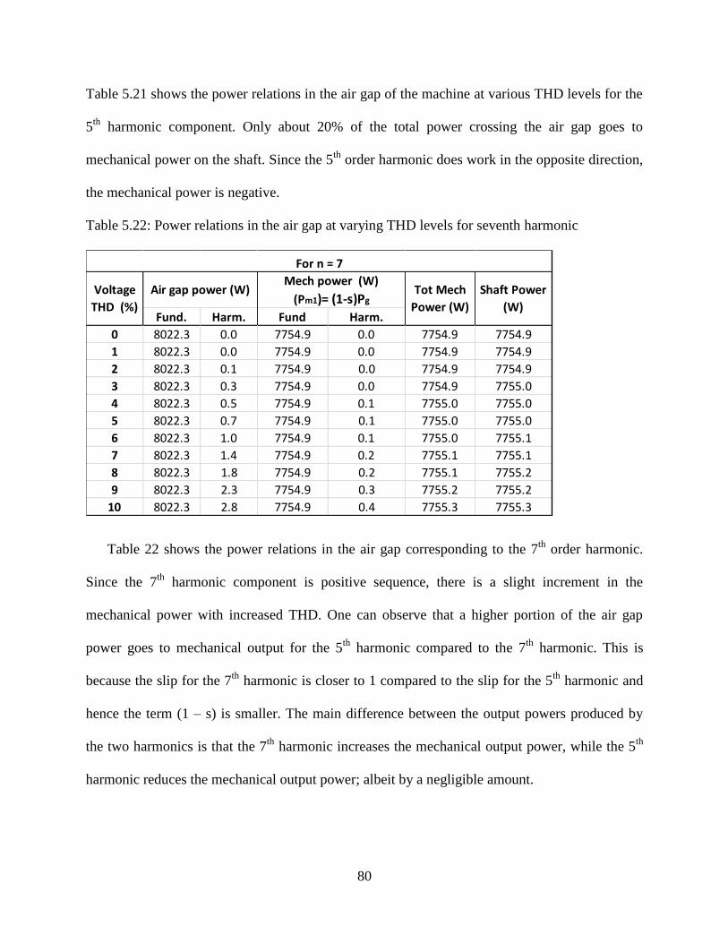
80
Table 5.21 shows the power relations in the air gap of the machine at various THD levels for the
5th
harmonic component. Only about 20% of the total power crossing the air gap goes to
mechanical power on the shaft. Since the 5th
order harmonic does work in the opposite direction,
the mechanical power is negative.
Table 5.22: Power relations in the air gap at varying THD levels for seventh harmonic
Table 22 shows the power relations in the air gap corresponding to the 7th
order harmonic.
Since the 7th
harmonic component is positive sequence, there is a slight increment in the
mechanical power with increased THD. One can observe that a higher portion of the air gap
power goes to mechanical output for the 5th
harmonic compared to the 7th
harmonic. This is
because the slip for the 7th
harmonic is closer to 1 compared to the slip for the 5th
harmonic and
hence the term (1 – s) is smaller. The main difference between the output powers produced by
the two harmonics is that the 7th
harmonic increases the mechanical output power, while the 5th
harmonic reduces the mechanical output power; albeit by a negligible amount.
Fund. Harm. Fund Harm.
0 8022.3 0.0 7754.9 0.0 7754.9 7754.9
1 8022.3 0.0 7754.9 0.0 7754.9 7754.9
2 8022.3 0.1 7754.9 0.0 7754.9 7754.9
3 8022.3 0.3 7754.9 0.0 7754.9 7755.0
4 8022.3 0.5 7754.9 0.1 7755.0 7755.0
5 8022.3 0.7 7754.9 0.1 7755.0 7755.0
6 8022.3 1.0 7754.9 0.1 7755.0 7755.1
7 8022.3 1.4 7754.9 0.2 7755.1 7755.1
8 8022.3 1.8 7754.9 0.2 7755.1 7755.2
9 8022.3 2.3 7754.9 0.3 7755.2 7755.2
10 8022.3 2.8 7754.9 0.4 7755.3 7755.3
For n = 7
Voltage
THD (%)
Air gap power (W)Mech power (W)
(Pm1)= (1-s)Pg Tot Mech
Power (W)
Shaft Power
(W)

81
Compared to the negative sequence 5th
harmonic component, the positive sequence 7th
order
harmonic seems to be less harmful to the machine. It produces positive torque and mechanical
power and leads to lesser losses than the 5th
order harmonic. However, it still has a negative
impact to the machine overall as it increases the losses and eventually leads to a decrease in the
efficiency. Therefore, both the 5th
and the 7th
order harmonics are harmful to the machine.
5.5 Comparison of the impacts of voltage asymmetry and voltage distortion
The effects of asymmetry and distortion were studied separately in the previous section. The
results presented earlier are presented side by side in this section, so as to have a comparison of
the effects of both voltage asymmetry and distortion on induction machines. Table 5.23 presents
a summary of the results.
Table 5.23: Comparison of effects of voltage asymmetry and distortion
It is clear that the impacts of voltage asymmetry are much more prominent than voltage
distortion. At the accepted level of 3%, voltage asymmetry reduces torque by 5% and leads to a
current asymmetry of 17.4%. At the same level of distortion, there is practically no reduction in
torque and the resulting current distortion is 3.8 %. At an asymmetry of 10%, losses are
THD/CUF level (%) 3% 10% 3% 10% 3% 10%
Increase in slip(%) 6 24 0 0 0 0
Reduction in Torque (%) 5 15 0 0 0 0
Increment in Losses (%) 6 48 0.1 1.7 0.06 0.8
Reduction in efficiency(%) 0.8 4.9 0 0.1 0 0.1
VUF/ CUF in current (%) 17.4 49.3 3.8 12.7 2.7 9
Comparison of the effects of voltage asymmetry and distortion on induction machine
Supply voltage distortionSupply voltage
asymmetry 5th Harmonic 7th Harmonic

82
increased by 48% and asymmetry in the current is 49%. At the same level of distortion,
increment in losses is negligible while the current distortion is 12%. Results suggest that voltage
asymmetry is much more harmful to the machine than voltage distortion. Whereas a machine is
practically unaffected by a voltage distortion in the supply of up to 10%, the same level of
asymmetry can be fatal to the machine if it persists. At an asymmetry level of 3%, although the
torque reduction and increment in losses are not alarming, resulting current asymmetry is in the
level of 17%, which can be very harmful to the system.
5.6 Conclusion
Most of the results obtained from computer modeling were found to be in accordance to those
predicted from theory. However, the losses in the stator were found to be higher than expected
while the losses in the rotor circuit were lower than expected. One of the reasons for this could
be the fact that the skin effect in the rotor was ignored. Since the rotor contains conductor in the
form of bars, skin effect might lead to significant increase of resistance. This could also be the
reason for why the effects of voltage distortion were so negligible. All the other results were as
expected. The simulation was only done for a single machine at a fixed load. Results will be
more reliable if the simulation is carried out for machines of different NEMA Machinery Design
Categories and sizes at various levels of output load. Overall, the results reiterated the theory
presented in the previous chapters of this thesis.

83
CHAPTER 6: CONCLUSION
Induction machines, the most common loads in the power system are designed to work under
symmetrical sinusoidal voltages. When they are subjected to voltage asymmetry and distortions,
there performance will change. Both voltage asymmetry and distortion have negative impacts on
the machine. Asymmetry leads to increment in losses and reductions in torque and efficiency.
Voltage distortion leads to increment in losses and reduction in efficiency. The torque maybe
increased or decreased as per the order of the harmonic.
Voltage asymmetry seems to be much more harmful to the machine than voltage
distortion from the perspective of machine performance as well as current response. At the
accepted level of 3% asymmetry, induction machine draws current at a level of 17% of
asymmetry. In other words, it acts like an amplifier of asymmetry. Thus the regulatory body
should reconsider whether or not an asymmetry level of 3% is benign when it is supplied to
induction machines.
Skin effects were ignored during the analysis in this thesis. This might be the reason for
why the effects of distortion on the machine were so negligible. The rotor resistance can
potentially be highly increased due to skin effects leading to increased losses. To consider these
effects, complete geometry of the machine is required. In that case the results will be more
reliable.

84
REFERENCES
[1] “ Power System Analysis”, Grainger,Stevenson
[2] “ Electric Machine Design”, Louisiana State University, EE 4422 Reference book.
[3] “Electric Machines”, Slemon, Straughen
[4] “Electric Machinery”,Fitzgerald,Kingsley,Umans
[5] “Effects of various unbalanced voltages on the operation performance of an induction motor
under the same voltage unbalance factor condition”, Chin - Ying Lee
[6] “Asymmetries in distribution systems: Causes, Harmful effects and Remedies”,Issac
Plummer
[7] “ Effects of unbalanced voltage on the operation of polyphase induction motors”, Woll.
[8] “Heating of induction motors on Unbalanced voltage”
[9] “Effects of unbalanced voltage on the operation performance of Three phase induction
motor.” Lee
[10] “Derating of Induction Motors Operating With a Combination of Unbalanced Voltages and
Over or Undervoltages”, Pillay
[11] “Loss of Life in Induction Machines Operating With Unbalanced Supplies”, Pillay
[12] “Effects of voltage harmonics on the electrical and mechanical performance of Three phase
induction motor”, Ching-Yin Lee.
[13] “Polyphase Induction Motor Performance and Losses on Non Sinusoidal Voltage Sources”,
Klingshirn.
[14] “ Harmonics and Power phenomena”, Leszek Czarnecki
[15] “ Electric Machinery”, Fitzgerald, Kingsley, Umans. Sixth edition pages(302 – 330)

85
APPENDIX A: NEMA MG-1 STANDARD FOR MACHINES AND GENERATORS
DESIGN PARAMETERS

86
APPENDIX B: MATLAB CODE FOR STUDYING THE RESPONSE OF THE
MACHINE UNDER SUPPLY VOLTAGE ASYMMETRY
% PROGRAM TO SEE THE RESPONSE OF INDUCTION MACHINE FOR ASYMMETRICAL SUPPLY
clear all;
% ELECTRICAL PARAMETERS
f = 60;
p = 6; % number of poles
pi = 22/7;
ns = 120 * f / p ; % synchronous speed rpm
omega_s = 2 * pi * ns/60 ; % synchronous angular freq
i = sqrt(-1);
% POSTIVE AND NEGATIVE SEQUENCE VOLTAGES ( from magnitude asymmetry)
VUF =[0,0.5,1,1.5,2,2.5,3,3.5,4,4.5,5];
% CORRESPONDING TO MAGNITUDE WITH 1 % INCREMENT
Vpt=[ 120-2.1316e-014i;118.95-0.60622i;117.95-1.1836i;116.9-1.7898i;115.96-2.3325i;115-2.8868i;114-
3.4641i;
113.1-3.9837i;112.2-4.5033i;111.3-5.0229i;110.4-5.5426i];
Vp = Vpt'
Vnt = [0;1.05+0.60622i;2.05+1.1836i;3.1+1.7898i;4.04+2.3325i;5+2.8868i;6+3.4641i;6.9+3.9837i;7.8+4.5033i;
8.7+5.0229i;9.6+5.5426i];
Vn=Vnt'
% MACHINE PARAMETERS g refers to given
Rsg =.294;
Rr = .144;
Xsg =.503;
Xr = .209;
Xmg = 13.25;
% USING THEVENIN THEOREM TO CALCULATE Req and Voltage
Zsth = 1i * Xmg * ( Rsg + 1i * Xsg) / ( Rsg + 1i * ( Xmg + Xsg));
Rsth = real(Zsth); % Dont confuse seq with sequence, this refers to stator thevenin equivalent
Xsth = imag(Zsth);
for cnt = 1:1:11
Vsth_p(cnt) = (Vp(cnt) * i * Xmg / ( Rsg + 1i * ( Xmg + Xsg))) ; % thevenin for postitiv seq
Vsth_n(cnt)= ( Vn(cnt) * i * Xmg / ( Rsg + 1i * ( Xmg + Xsg))) ; % thevenin for negative seq
rpm=[0 : 1 : ns];
%Caclulation of torque and other quantities
Tem = 0;
n=0;
for n = 1 : 1 : ns+1;
sp(n)= (ns - rpm(n))/ns;
sn(n) = (-ns - rpm(n) )/ (-ns);
omega_r(n) = 2 * pi * rpm(n) /60;
Irp(n) = ( Vsth_p(cnt) / ( Zsth + i*Xr + Rr/sp(n)));
Irn(n) = ( Vsth_n(cnt)/ ( Zsth + i*Xr + Rr/sn(n)));
87
Ztot_p = ( Rsg + 1i * Xsg) + (i*Xmg * ( i* Xr + Rr/sp(n))/ (i*Xmg + i* Xr + Rr/sp(n)));
Ztot_n = ( Rsg + 1i * Xsg) + (i*Xmg * ( i* Xr + Rr/sn(n))/ (i*Xmg + i* Xr + Rr/sn(n)));
Is_p(n) = Vp(cnt) / Ztot_p ;
Is_n(n) = Vn(cnt) / Ztot_n ;
Is(n) = Is_p(n)+Is_n(n);
Tem_p(n) = 3 * (abs(Irp(n)))^2 * Rr / ( sp(n) * omega_s);
Tem_n(n) = -3 * (abs(Irn(n)))^2 * Rr / ( sn(n) *omega_s);
Tem(n)= Tem_p(n) + Tem_n(n);
if abs(Tem(n) - Tl)< 2
if (n > 1000)
disp(' ')
fprintf ('The speed at which motor runs is:%g \n',rpm(n))
%disp(n);
break;
end
end
end
Pin_p = 3 * real( Vp(cnt) * conj(Is_p(n))) ;
Pin_n= 3 * real( Vn(cnt) * conj(Is_n(n)));
Pin_tot = Pin_p + Pin_n;
Istat_p= Is_p(n);
Irot_p = Irp(n);
Istat_n= Is_n(n);
Irot_n = Irn(n);
P_los_stat_p = 3 * (abs(Is_p(n))^2)*Rsg;
P_los_stat_n = 3 * (abs(Is_n(n))^2)*Rsg;
Pg_p = 3 * (abs(Irp(n)))^2 * Rr / sp(n);
Pg_n = 3 * (abs(Irn(n)))^2 * Rr / sn(n);
Pg_p_mech = (1 - sp(n))* Pg_p;
Pg_n_mech = ( 1 - sn(n))* Pg_n;
Pshaft = Tem(n) * omega_r(n);
P_los_rot_p= 3 * (abs(Irp(n)))^2 * Rr ;% losses in the rotor corcuits
P_los_rot_n= 3 * (abs(Irn(n)))^2 * Rr ;% losses in the rotor circuits
%
efi = 100*Pshaft / (Pin_tot) ; % considering just postive air gap power as input power to machine
P_los_tot = Pin_tot - Pshaft;
st_pos_loss(cnt)= P_los_stat_p;
st_neg_loss(cnt)=P_los_stat_n;
rot_pos_loss(cnt)= P_los_rot_p;
rot_neg_loss(cnt)=P_los_rot_n;
spd(cnt)=rpm(n);
T_em(cnt)=Tem(n);
tot_loss(cnt) = P_los_tot;
P_loss_pos_tot(cnt)=P_los_rot_p + P_los_stat_p;
efficiency(cnt)=efi;
88
P_pos_in(cnt)=Pin_p;
P_neg_in(cnt)=Pin_n;
P_pos_gap(cnt)=Pg_p;
P_neg_gap(cnt)=Pg_n;
P_out(cnt)=Pshaft;
P_pos_mech(cnt)=Pg_p_mech;
P_neg_mech(cnt)=Pg_n_mech;
I_stat_p(cnt)= abs(Is_p(n));
I_stat_n(cnt)= abs(Is_n(n));
CUF_stat(cnt)=100 * (I_stat_n(cnt)/I_stat_p(cnt));
I_r_p(cnt)= abs(Irp(n));
I_r_n(cnt)= abs(Irn(n));
CUF_r(cnt)=100 * (I_r_n(cnt)/I_r_p(cnt));
end

89
APPENDIX C: MATLAB CODE FOR STUDYING THE RESPONSE OF THE
MACHINE UNDER SUPPLY VOLTAGE DISTORTION
% PROGRAM TO SEE THE RESPONSE OF INDUCTION MACHINE FOR DISTORTED SUPPLY
clear all;
% ELECTRICAL PARAMETERS
f = 60;
p = 6; % number of poles
pi = 22/7;
nf = 120 * f / p ; % synchronous speed rpm
omega_s_f = 2 * pi * nf/60 ; % synchronous angular freq
i = sqrt(-1);
k = 5; % Order of harmonic
nh = - k * nf; % synchronous speed in rpm of the harmonic /.. - 5 for 5th and 7 for 7th
omega_s_h = 2 * pi * nh/60; % synh speed in radians/sec for harmonic
Vf = 120;
Vhn= [0,1.2,2.4,3.6,4.8,6.0,7.2,8.4,9.6,10.8,12];
THD =[0,1,2,3,4,5,6,7,8,9,10] ;
Tl = 62 ; % initialization of load torque
% MACHINE PARAMETERS g refers to given
Rsg = .294;
Rr = .144;
Xsg = .503;
Xr = .209;
Xmg = 13.25;
% USING THEVENIN THEOREM TO CALCULATE Req and Voltage
Zsth = 1i * Xmg * ( Rsg + 1i * Xsg) / ( Rsg + 1i * ( Xmg + Xsg));
Rsth = real(Zsth); % Dont confuse seq with sequence, this refers to stator equivalent
Xsth = imag(Zsth);
% Impedance for harmonics :
Zsth_h = 1i * k * Xmg * ( Rsg + 1i * k * Xsg) / ( Rsg + 1i * k* ( Xmg + Xsg));
Rsth_h = real(Zsth_h); % Dont confuse seq with sequence, this refers to stator equivalent
Xsth_h = imag(Zsth_h);
cnter = 0;
for cnter = 1 : 1 : 11
Vh = Vhn(cnter);

90
% disp(' ')
disp('------------------------------------')
% fprintf('Results for THD = %g \n',THD(cnter))
% fprintf(' load torque %g \n',Tl);
% fprintf(' harmonic order = %g \n', k);
%disp('Results for Vn ='),(Vn)
Vsth_f = ( Vf * i * Xmg / ( Rsg + 1i * ( Xmg + Xsg))) ; % thevenin for fundamental
Vsth_h = ( Vh * i * k * Xmg / ( Rsg + 1i * k * ( Xmg + Xsg))) ; % thevenin for harmonic
% CALCULATION OF PARAMETERS
% Caclulation of torque and other paramters
% Tem = 0;
n=0;
rpm=0:1:nf ;
for n = 1 : 1 : nf+1;
sf(n)= (nf - rpm(n))/nf;
sh(n) = (nh - rpm(n) )/ (nh);
omega_r(n) = 2 * pi * rpm(n) /60;
Ir_f(n) = ( Vsth_f / ( Zsth + i*Xr + Rr/sf(n)));
Ir_h(n) = ( Vsth_h / ( Zsth_h + i*k*Xr + Rr/sh(n)));
Ztot_f = ( Rsg + 1i * Xsg) + (i*Xmg * ( i* Xr + Rr/sf(n))/ (i*Xmg + i* Xr + Rr/sf(n)));
Ztot_h = ( Rsg + 1i *k* Xsg) + (i*Xmg *k* ( i*k* Xr + Rr/sh(n))/ (i*k*Xmg + i*k* Xr +
Rr/sh(n)));
Is_f(n) = Vf / Ztot_f ;
Is_h(n) = Vh / Ztot_h ;
Tem_f(n) = 3 * (abs(Ir_f(n)))^2 * Rr / ( sf(n) * omega_s_f);
Tem_h(n) = 3 * (abs(Ir_h(n)))^2 * Rr / ( sh(n) * omega_s_h);
Tem(n)= Tem_f(n) + Tem_h(n);
if abs(Tem(n) - Tl)< 2
if (n>1100)
% fprintf ('The speed at which motor runs is:%g \n',rpm(n))
% fprintf ('fundame slip :%g \n',sf(n))
% fprintf ('harmonic slip:%g \n',sh(n))
%disp(n);
break;
end
end
end
%CALCULATION OF DIFFERENT POWERS IN THE MACHINE
91
I_st_f = abs(Is_f(n));
I_st_h = abs(Is_h(n));
I_rot_f = abs(Ir_f(n));
I_rot_h = abs(Ir_h(n));
Vtf= abs(Vsth_f);
Vth=abs(Vsth_h);
Pin_f = 3 * real( Vf * conj(Is_f(n))) ;
Pin_h= 3 * real( Vh * conj(Is_h(n)));
Pin_tot = Pin_f + Pin_h;
P_los_stat_f = 3 * (abs(Is_f(n))^2)*Rsg;
P_los_stat_h = 3 * (abs(Is_h(n))^2)*Rsg;
Pg_f = 3 * (abs(Ir_f(n)))^2 * Rr / sf(n);
Pg_h = 3 * (abs(Ir_h(n)))^2 * Rr / sh(n);
Pshaft = Tem(n) * omega_r(n);
P_los_rot_f= 3 * (abs(Ir_f(n)))^2 * Rr ;% losses in the rotor corcuits
P_los_rot_h= 3 * (abs(Ir_h(n)))^2 * Rr ;% losses in the rotor circuits
efi = Pshaft / (Pin_tot) ; % considering just postive air gap power as input power to machine
P_los_tot = Pin_tot - Pshaft;
I_st_f = abs(Is_f(n));
I_st_h = abs(Is_h(n));
I_rot_f = abs(Ir_f(n));
I_rot_h = abs(Ir_h(n));
P_lo_st_f(cnter)= P_los_stat_f;
P_lo_st_h(cnter)=P_los_stat_h;
P_lo_rot_f(cnter)= P_los_rot_f;
P_lo_rot_h(cnter)=P_los_rot_h;
effic(cnter)=efi*100;
P_input_f(cnter)=Pin_f;
P_input_h(cnter)=Pin_h;
P_gap_f(cnter)=Pg_f;
P_gap_h(cnter)=Pg_h;
P_out(cnter)=Pshaft;
P_mech_f(cnter)= (1-sf(n)) * P_gap_f(cnter);
P_mech_h(cnter)= (1-sh(n)) * P_gap_h(cnter);
end

92
VITA
Prashanna Dev Bhattarai was born in Kathmandu, Nepal in April, 1984. He graduated
from his high school, St. Xavier’s Campus, in 2003. He attended Pulchowk Engineering Campus
for the study of Bachelor of Electrical Engineering. Upon graduating in 2008, he worked for a
year in Nepal before joining the Department of Electrical Engineering at Louisiana State
University in 2009. He is currently pursuing his PhD in Electrical Engineering at Louisiana State
University, where he is also employed as a Teaching Assistant. He worked as a Summer Intern at
the Entergy Transmission and Distribution Headquarters in Jackson, MS in the summer of 2012.