study on gas hydrate blocking mechanism and precaution in
TRANSCRIPT

Study on Gas Hydrate Blocking Mechanism
and Precaution in Wellbore of Deep Water
Drilling
Shujie Liu, Xiangfang Li*, Bangtang Yin, Yunjian Zhou, Lianwang Zhu
1
Shujie Liu, Xiangfang Li*, Bangtang Yin, Yunjian Zhou, Lianwang Zhu
College of Petroleum Engineering
China University of Petroleum (Beijing)
[email protected], [email protected]
http://www.cup.edu.cn/oil/teachers/field/87641.htm
OutlineOutlineOutlineOutline
� Introduction
� Multiphase flow influence on the hydrate blocking
� Hydrate blocking prediction and prevention during
the whole drilling process
� Conclusion
1.Introduction1.Introduction1.Introduction1.Introduction
Gas hydrate will be easily formed under the deepwater
drilling condition.
� High pressure and low temperature around the
mud linemud line
� Complicated pressure and temperature in the
wellbore

The formation of gas hydrates during deepwater
drilling may have several such adverse effects as:
� Blocking the choke line and well kill line, which prevents
their use in well circulation;
� Plug formation at or below the BOP’s, which prevents
1.Introduction1.Introduction1.Introduction1.Introduction
well pressure monitoring below the BOP’s;
� Plug formation around the drillstring in the riser, BOP’s,
or casing, which prevents drillstring movement;
� Plug formation between the drillstring and the BOP’s,
which prevents full BOP closure;
� Plug formation in the ram cavity of a closed BOP, which
prevents the BOP from fully opening.
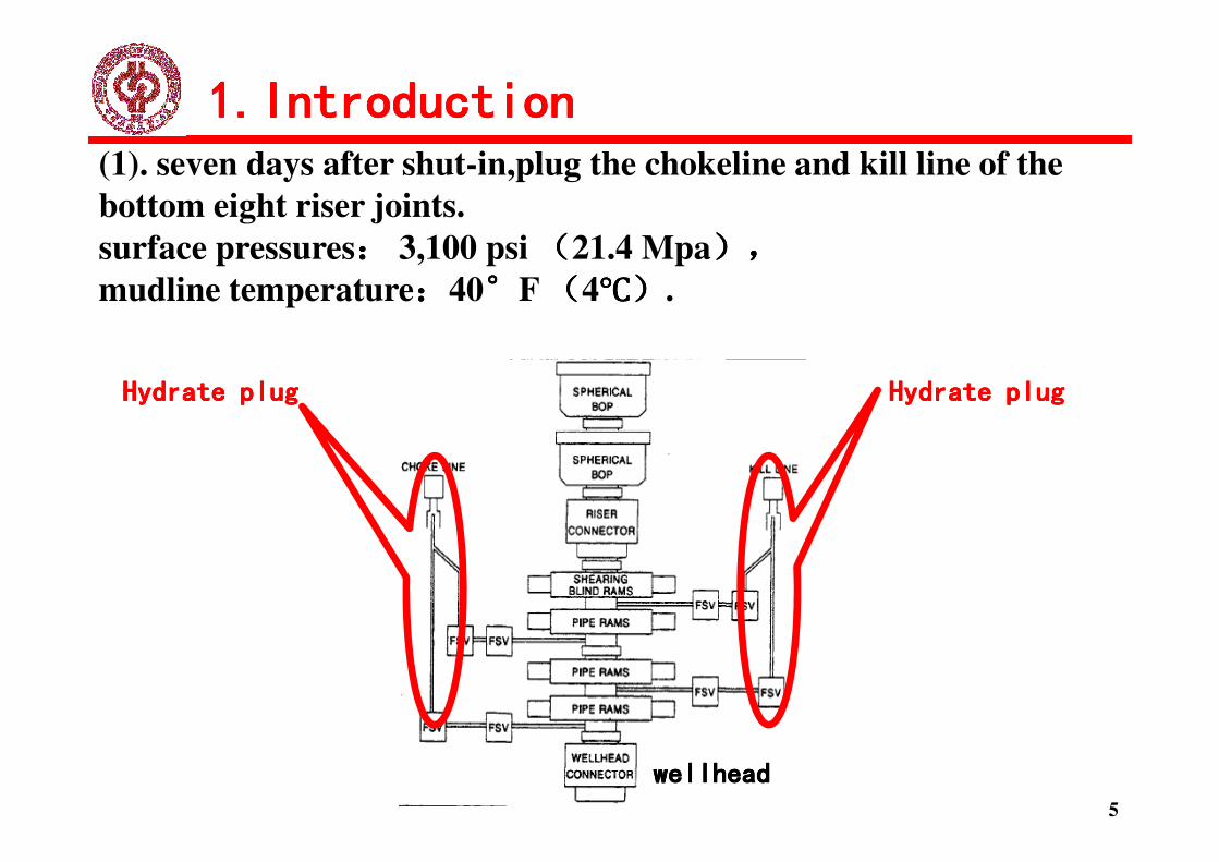
Hydrate plugHydrate plugHydrate plugHydrate plug Hydrate plugHydrate plugHydrate plugHydrate plug
(1). seven days after shut-in,plug the chokeline and kill line of the
bottom eight riser joints.
surface pressures:::: 3,100 psi ((((21.4 Mpa),),),),
mudline temperature::::40°°°°F ((((4℃℃℃℃)))).
1.Introduction1.Introduction1.Introduction1.Introduction
wellheadwellheadwellheadwellhead
5

(2). plug formation at or below the BOP's
1.Introduction1.Introduction1.Introduction1.Introduction
6
wellheadwellheadwellheadwellhead
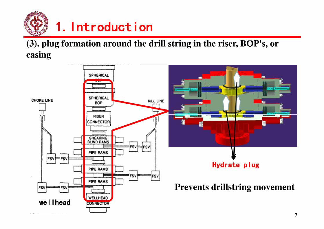
(3). plug formation around the drill string in the riser, BOP's, or
casing
1.Introduction1.Introduction1.Introduction1.Introduction
wellheadwellheadwellheadwellhead
Hydrate plugHydrate plugHydrate plugHydrate plug
7
Prevents drillstring movement
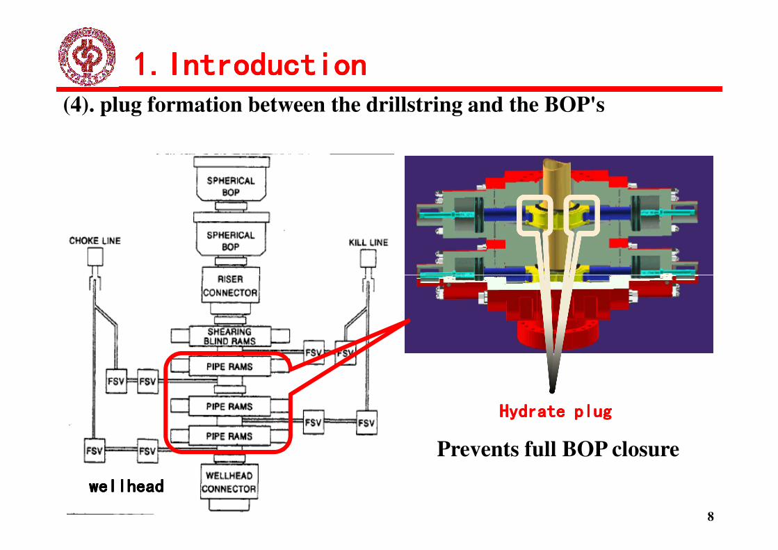
(4). plug formation between the drillstring and the BOP's
1.Introduction1.Introduction1.Introduction1.Introduction
8
Hydrate plugHydrate plugHydrate plugHydrate plug
Prevents full BOP closure
wellheadwellheadwellheadwellhead
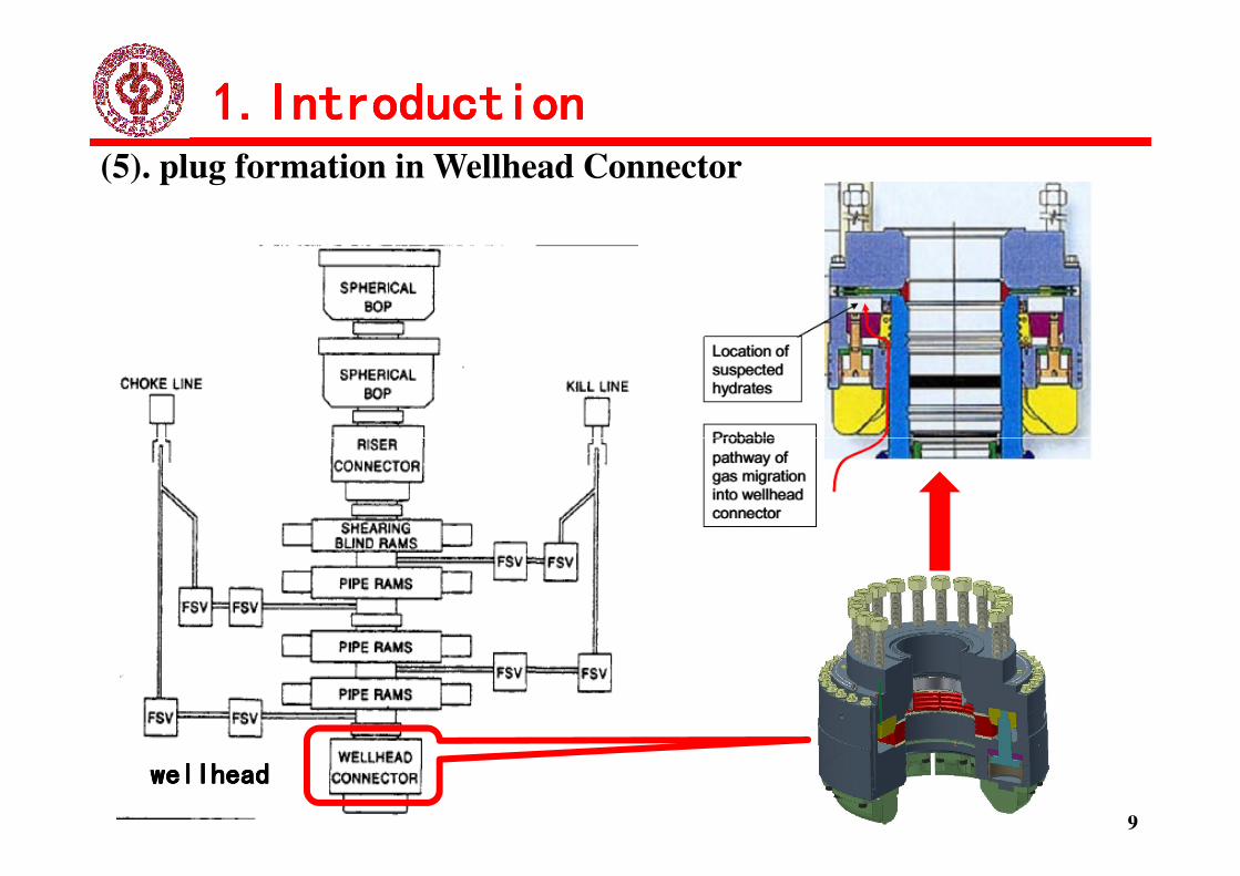
(5). plug formation in Wellhead Connector
1.Introduction1.Introduction1.Introduction1.Introduction
wellheadwellheadwellheadwellhead
9
1.Introduction1.Introduction1.Introduction1.Introduction
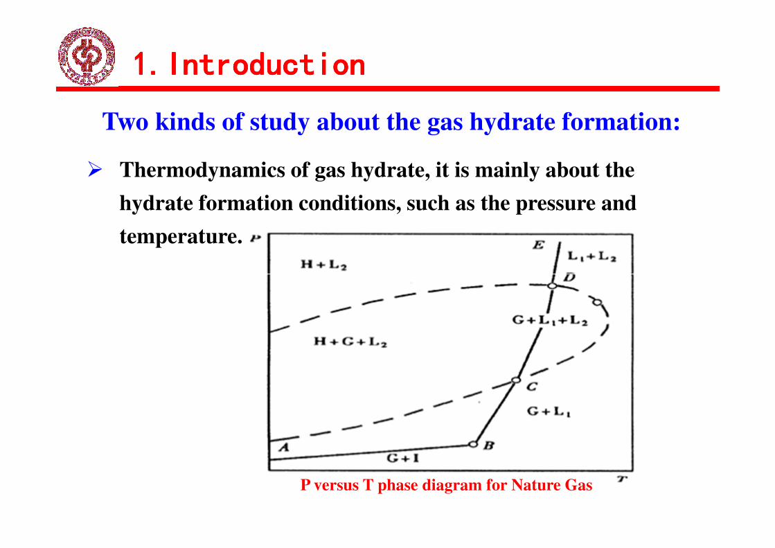
Two kinds of study about the gas hydrate formation:
� Thermodynamics of gas hydrate, it is mainly about the
hydrate formation conditions, such as the pressure and
temperature.
1.Introduction1.Introduction1.Introduction1.Introduction
P versus T phase diagram for Nature Gas

Two kinds of study about the gas hydrate formation:
� Kinetics of hydrate formation, it is mainly about the gas
hydrate formation and dissociation speed.
1.Introduction1.Introduction1.Introduction1.Introduction
(a) Gas consumption vs. time for hydrate
formation
(b) Temperature and pressure
trace for formation of simple methane
hydrates.
Most researchers believed that gas hydrate would formed
when the condition was in the hydrate formation area of the
phase diagram and predicted the hydrate formation area
based on the thermodynamics theory .
� Gao Y H, Wang Z Y, Johnny P predicted the hydrate formation area
based on the Van der Waals and Platteeuw theory.
1.Introduction1.Introduction1.Introduction1.Introduction
� Kotkoskle T K, Peavy M A, Yousif M H, Thierry B studied the
hydrate inhibition based on the thermodynamics theory.
� Chen S M studied the prevention of gas hydrate formation during the
deepwater well suddenly shut in.
The kinetics should also be considered in the gas
hydrate formation prediction.

Some researchers believed that the hydrate inhibitor
helped prevent the hydrate formation in the whole drilling
process. It was high input and wasteful. They mistook
hydrate formation as blocking. Based on the hydrate kinetic
1.Introduction1.Introduction1.Introduction1.Introduction
theory, the hydrate formation is different from the hydrate
blocking. Based on the blocking mechanism, there is no
need to use the hydrate inhibitor in most part of deepwater
drilling.

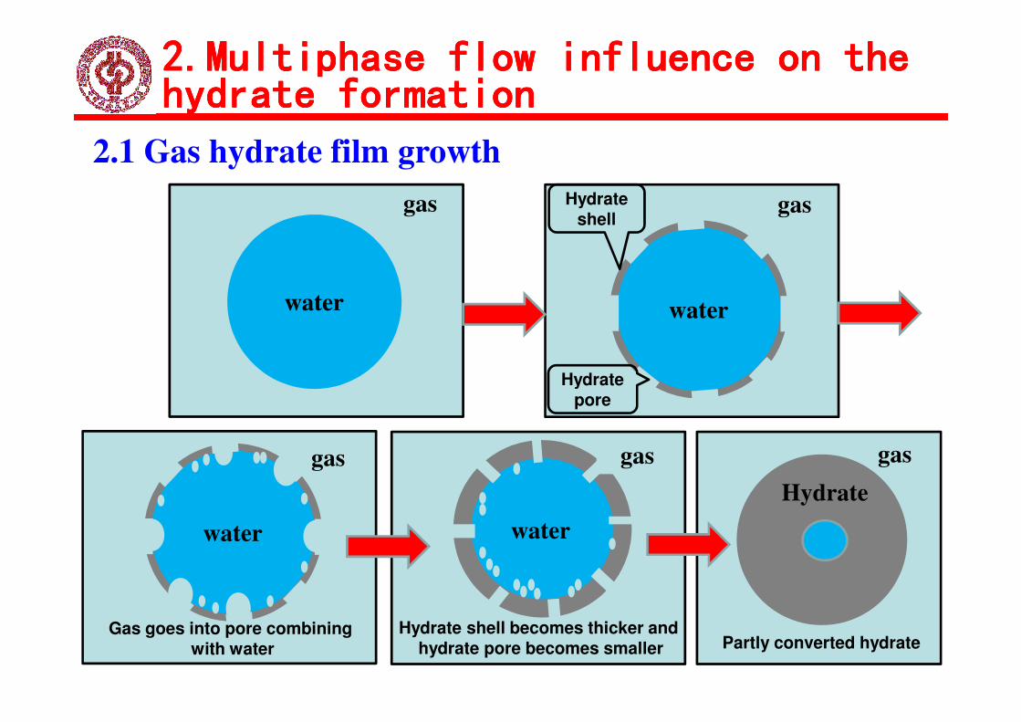
2.1 Gas hydrate film growth
A conceptual picture of the proposed mechanism for hydrate
film growth at the hydrocarbon–water interface based on the
above experimental results is given:
� Step 1: Propagation of a thin porous hydrate shell (film) around the
2.Multiphase flow influence on the 2.Multiphase flow influence on the 2.Multiphase flow influence on the 2.Multiphase flow influence on the
hydrate formationhydrate formationhydrate formationhydrate formation
� Step 1: Propagation of a thin porous hydrate shell (film) around the
water droplet.
� Step 2: Shell development.
� Step 3: Bulk conversion of the droplet interior to hydrate
water
gas
water
gasHydrate shell
2.1 Gas hydrate film growth
2.Multiphase flow influence on the 2.Multiphase flow influence on the 2.Multiphase flow influence on the 2.Multiphase flow influence on the
hydrate formationhydrate formationhydrate formationhydrate formation
16
water
gas
Gas goes into pore combiningwith water
water
gas
Hydrate shell becomes thicker andhydrate pore becomes smaller
gas
Hydrate
Partly converted hydrate
Hydratepore

2.2 The gas hydrate formation will be slowly when
there is no surfactant and no stirring.
� Sun Z G found that there was no hydrate formation in the static
system during 32 hours but when mixed up, hydrate formed after 5-
10 mins.
2.Multiphase flow influence on the 2.Multiphase flow influence on the 2.Multiphase flow influence on the 2.Multiphase flow influence on the
hydrate formationhydrate formationhydrate formationhydrate formation
10 mins.
� Ryo Ohmura et al believed that the gas hydrate film in the interface
of hydrate slowed down the formation speed in the static condition.
� Jesen et al studied the hydrate formation during different stirring
speed and different surfactants, found that high stirring speed could
reduced the hydrate formation time.
2.3 The gas hydrate film slow down the hydrate
formation
� The dissolved gas concentration is low and the mass transfer is
the dominant. Only 0.1% gas can be dissolved in the water
phase, however, there are 15% mol gas in the gas hydrate
2.Multiphase flow influence on the 2.Multiphase flow influence on the 2.Multiphase flow influence on the 2.Multiphase flow influence on the
hydrate formationhydrate formationhydrate formationhydrate formation
phase, however, there are 15% mol gas in the gas hydrate
particles, which is at least 100 times than the gas solubility.
The mass transfer from gas to the hydrate surface is
important.

2.3 The gas hydrate film slow down the hydrate
formation
� The gas hydrate can be formed on the interface of gas bubble
and liquid phase. The thickness of gas hydrate on the bubble
surface increased quickly in the beginning. After reaching a
2.Multiphase flow influence on the 2.Multiphase flow influence on the 2.Multiphase flow influence on the 2.Multiphase flow influence on the
hydrate formationhydrate formationhydrate formationhydrate formation
surface increased quickly in the beginning. After reaching a
certain thickness, it would not increase, stopping the dissolved
gas molecule transferring from gas phase to liquid phase. And
the mass transfer would be influenced.

2.Multiphase flow influence on the 2.Multiphase flow influence on the 2.Multiphase flow influence on the 2.Multiphase flow influence on the
hydrate formationhydrate formationhydrate formationhydrate formation
2.4 No hydrate blocking in the bubble flow during
mud in circulation
� In bubble flow, the mass transfer coefficient is small. The induction time
of gas hydrate formation is long because of the low gas concentration at
the interface. During the induction time, the fluid under the hydrate
formation condition flow out of the wellbore.
� The amount of formed hydrate are few, and will be affected by the
flowing drilling fluid. They will fall off the wellbore wall and flow with
the drilling fluid out of the wellbore.

2.Multiphase flow influence on the 2.Multiphase flow influence on the 2.Multiphase flow influence on the 2.Multiphase flow influence on the
hydrate formationhydrate formationhydrate formationhydrate formation
2.4 No hydrate blocking in the bubble flow during
mud in circulation
Circulation timeCirculation timeCirculation timeCirculation time
Schematic illustration of cross-sectional view of
hydrate film
riserriserriserriser
Low temperatureLow temperatureLow temperatureLow temperature
Schematic of the proposed mechanism for hydrate
formation from a water droplet.
mud linemud linemud linemud line

2.Multiphase flow influence on the 2.Multiphase flow influence on the 2.Multiphase flow influence on the 2.Multiphase flow influence on the
hydrate formationhydrate formationhydrate formationhydrate formation
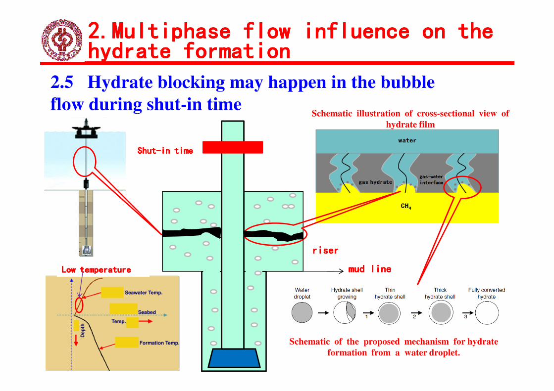
2.5 Hydrate blocking may happen in the bubble
flow during shut-in time
� During the shut-in time, because the temperature of drilling
mud in the riser decreases, the impact effect of drilling fluid
on gas hydrate weakens , Hydrate blocking may happen in on gas hydrate weakens , Hydrate blocking may happen in
riser.
2.Multiphase flow influence on the 2.Multiphase flow influence on the 2.Multiphase flow influence on the 2.Multiphase flow influence on the
hydrate formationhydrate formationhydrate formationhydrate formation
2.5 Hydrate blocking may happen in the bubble
flow during shut-in timeSchematic illustration of cross-sectional view of
hydrate film
ShutShutShutShut----in timein timein timein time
riserriserriserriser
Low temperatureLow temperatureLow temperatureLow temperature
Schematic of the proposed mechanism for hydrate
formation from a water droplet.
mud linemud linemud linemud line

2.Multiphase flow influence on the 2.Multiphase flow influence on the 2.Multiphase flow influence on the 2.Multiphase flow influence on the
hydrate formationhydrate formationhydrate formationhydrate formation
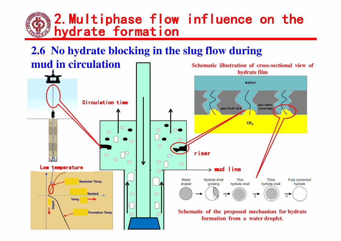
2.6 No hydrate blocking in the slug flow during
mud in circulation
� There are liquid film in the drilling pipe wall and casing wall, Taylor
bubble in the center of the wellbore in slug flow. Compared with the same
volume of gas bubbles, the total contact area of the gas / liquid interface
decrease, and the mass transfer decrease.
� During the induction time of hydrate formation, the fluid under the � During the induction time of hydrate formation, the fluid under the
hydrate formation condition flow out of the wellbore.
� The hydrate film can be formed in the drilling pipe wall and casing wall
after the induction time. However, the amount of hydrate are still few
because of the low gas concentration in the interface. The formed hydrate
fall off the pipe wall and flow out of the wellbore.
2.Multiphase flow influence on the 2.Multiphase flow influence on the 2.Multiphase flow influence on the 2.Multiphase flow influence on the
hydrate formationhydrate formationhydrate formationhydrate formation
2.6 No hydrate blocking in the slug flow during
mud in circulation
Circulation timeCirculation timeCirculation timeCirculation time
Schematic illustration of cross-sectional view of
hydrate film
riserriserriserriser
Low temperatureLow temperatureLow temperatureLow temperature
Schematic of the proposed mechanism for hydrate
formation from a water droplet.
mud linemud linemud linemud line

2.Multiphase flow influence on the 2.Multiphase flow influence on the 2.Multiphase flow influence on the 2.Multiphase flow influence on the
hydrate formationhydrate formationhydrate formationhydrate formation
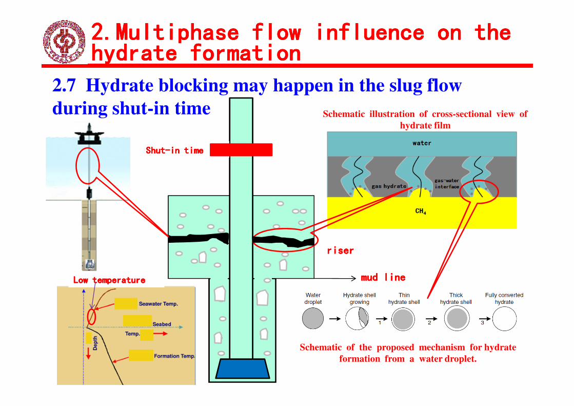
2.7 Hydrate blocking may happen in the slug flow
during shut-in time
� During the shut-in time, because the temperature of drilling mud in
the riser decreases, the impact effect of drilling fluid on gas hydrate
weakens , Hydrate blocking may happen in riser.weakens , Hydrate blocking may happen in riser.
2.Multiphase flow influence on the 2.Multiphase flow influence on the 2.Multiphase flow influence on the 2.Multiphase flow influence on the
hydrate formationhydrate formationhydrate formationhydrate formation
2.7 Hydrate blocking may happen in the slug flow
during shut-in time Schematic illustration of cross-sectional view of
hydrate film
ShutShutShutShut----in timein timein timein time
riserriserriserriser
Low temperatureLow temperatureLow temperatureLow temperature
Schematic of the proposed mechanism for hydrate
formation from a water droplet.
mud linemud linemud linemud line
2.Multiphase flow influence on the 2.Multiphase flow influence on the 2.Multiphase flow influence on the 2.Multiphase flow influence on the
hydrate formationhydrate formationhydrate formationhydrate formation
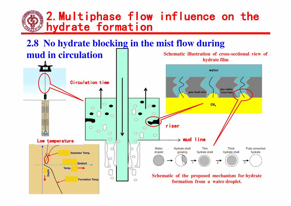
2.8 No hydrate blocking in the mist flow during
mud in circulation
� When the mist flow occurs, the discrete droplets are distributed in the
continuous gas phase. The drilling fluid velocity is fast and the convective
heat transfer coefficient is large, so the heat transfer is large and the loss of
heat is few. The fluid temperature is high enough to prevent the hydrate heat is few. The fluid temperature is high enough to prevent the hydrate
formation.
� If the throttle devices are installed on the wellhead, the fluid temperature
will be drastically reduced due to the Joule Thomson effect. The hydrate
will be formed around the wellhead.
2.Multiphase flow influence on the 2.Multiphase flow influence on the 2.Multiphase flow influence on the 2.Multiphase flow influence on the
hydrate formationhydrate formationhydrate formationhydrate formation
2.8 No hydrate blocking in the mist flow during
mud in circulation
Circulation timeCirculation timeCirculation timeCirculation time
Schematic illustration of cross-sectional view of
hydrate film
riserriserriserriser
Low temperatureLow temperatureLow temperatureLow temperature
Schematic of the proposed mechanism for hydrate
formation from a water droplet.
mud linemud linemud linemud line
2.Multiphase flow influence on the 2.Multiphase flow influence on the 2.Multiphase flow influence on the 2.Multiphase flow influence on the
hydrate formationhydrate formationhydrate formationhydrate formation
2.9 Hydrate blocking may happen in the mist flow
during shut-in time
� During the shut-in time, because the temperature of drilling
mud in the riser decreases, the impact effect of drilling fluid
on gas hydrate weakens , Hydrate blocking may happen in on gas hydrate weakens , Hydrate blocking may happen in
riser.

2.Multiphase flow influence on the 2.Multiphase flow influence on the 2.Multiphase flow influence on the 2.Multiphase flow influence on the
hydrate formationhydrate formationhydrate formationhydrate formation
2.9 Hydrate blocking may happen in the mist flow
during shut-in time Schematic illustration of cross-sectional view of
hydrate film
ShutShutShutShut----in timein timein timein time
riserriserriserriser
Low temperatureLow temperatureLow temperatureLow temperature
Schematic of the proposed mechanism for hydrate
formation from a water droplet.
mud linemud linemud linemud line

When the overflow occurs, the fluid rate in the wellbore is higher, at this moment, in
the wellbore maybe form hydrates. If the buoyancy of bubble is larger than viscosity,
bubble goes up in the wellbore passby the BOP position. But as hydrate crystals
generated gradually at the gas surface, then it will form a thin hydrate shell. Once
bubble surface coverd fully by hydrates, the generation and reaction rate of hydrates
will slow down, during this time, hydrates had formed mostly got rid of wellbore by the
(1).When the gas kick occurs, in the BOP position
hydrates plug will not form.
3.Hydrate blocking prediction and 3.Hydrate blocking prediction and 3.Hydrate blocking prediction and 3.Hydrate blocking prediction and
prevention during the whole drillprevention during the whole drillprevention during the whole drillprevention during the whole drill
32
will slow down, during this time, hydrates had formed mostly got rid of wellbore by the
higher rate, and this time the BOP position is a smooth channel, without bent and other
corner, so hydrates will not accumulate in the BOP position and will not plug.
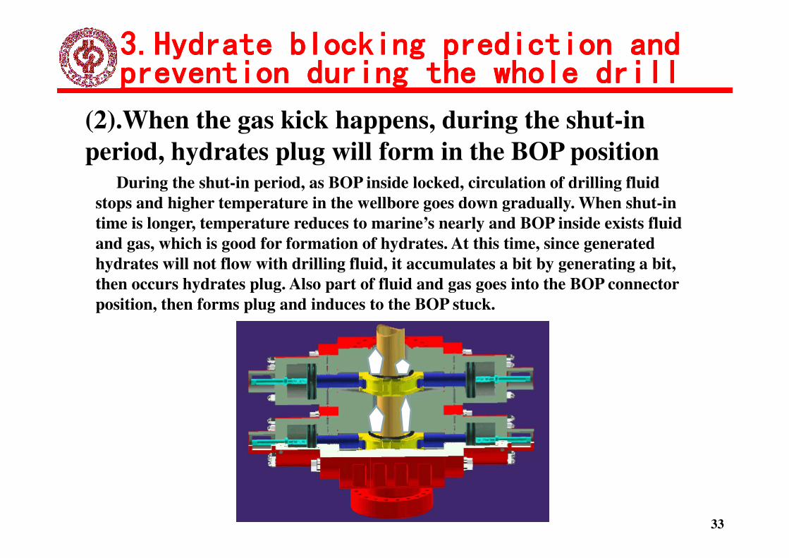
(2).When the gas kick happens, during the shut-in
period, hydrates plug will form in the BOP positionDuring the shut-in period, as BOP inside locked, circulation of drilling fluid
stops and higher temperature in the wellbore goes down gradually. When shut-in
time is longer, temperature reduces to marine’s nearly and BOP inside exists fluid
and gas, which is good for formation of hydrates. At this time, since generated
hydrates will not flow with drilling fluid, it accumulates a bit by generating a bit,
then occurs hydrates plug. Also part of fluid and gas goes into the BOP connector
3.Hydrate blocking prediction and 3.Hydrate blocking prediction and 3.Hydrate blocking prediction and 3.Hydrate blocking prediction and
prevention during the whole drillprevention during the whole drillprevention during the whole drillprevention during the whole drill
33
then occurs hydrates plug. Also part of fluid and gas goes into the BOP connector
position, then forms plug and induces to the BOP stuck.

(3). During the well kill with the driller's method
and engineering method, it won’t plug.
During the process of kill in the d
riller's method and engineering m
ethod, though pressure and tempe
rature maybe up to hydrates form
3.Hydrate blocking prediction and 3.Hydrate blocking prediction and 3.Hydrate blocking prediction and 3.Hydrate blocking prediction and
prevention during the whole drillprevention during the whole drillprevention during the whole drillprevention during the whole drill
34
ation’s and with enough bubble,
which means generating hydrates.
But as the circulation of drilling
fluid, generated hydrates fall off a
t any time, without enough time
to fit hydrates’ accumulation at
the bend, so it won’t plug.

(4). During the process of kill in the static displacement
method, it may form plug at the wellhead.
During the process of kill in the static
displacement method, with enough
temperature and pressure forms
3.Hydrate blocking prediction and 3.Hydrate blocking prediction and 3.Hydrate blocking prediction and 3.Hydrate blocking prediction and
prevention during the whole drillprevention during the whole drillprevention during the whole drillprevention during the whole drill
temperature and pressure forms
hydrates. As for this method, if the
waiting time of exchanging between
gas and kill fluid is too long, it may
forms plug at the wellhead.
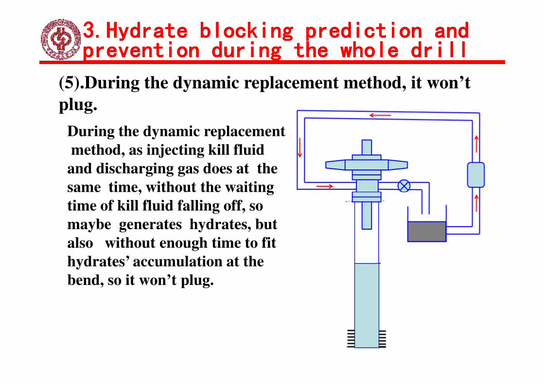
(5).During the dynamic replacement method, it won’t
plug.
During the dynamic replacement
method, as injecting kill fluid
and discharging gas does at the
same time, without the waiting
3.Hydrate blocking prediction and 3.Hydrate blocking prediction and 3.Hydrate blocking prediction and 3.Hydrate blocking prediction and
prevention during the whole drillprevention during the whole drillprevention during the whole drillprevention during the whole drill
same time, without the waiting
time of kill fluid falling off, so
maybe generates hydrates, but
also without enough time to fit
hydrates’ accumulation at the
bend, so it won’t plug.

(1). No hydrate blocking happens in the bubble flow during mud
in circulation .
①①①① In bubble flow, the mass transfer coefficient is small.
②②②② The fluid under the hydrate formation condition flow out of the wellbore.
③③③③ The formed hydrate are few, and will be affected by the flowing drilling
4.Conclution4.Conclution4.Conclution4.Conclution
③③③③ The formed hydrate are few, and will be affected by the flowing drilling
fluid. They will fall off the wellbore wall and flow with the drilling fluid out of
the wellbore.
(2). No hydrate blocking happens in the slug flow during mud in
circulation.
①①①① During the induction time of hydrate formation, the fluid under the
hydrate formation condition flow out of the wellbore.
②②②② The amount of hydrate are still few because of the low gas concentration
4.Conclution4.Conclution4.Conclution4.Conclution
②②②② The amount of hydrate are still few because of the low gas concentration
in the interface. The formed hydrate fall off the pipe wall and flow out of the
wellbore.

(3). No hydrate blocking happens in the mist flow during mud in
circulation.
When the mist flow occurs, the discrete droplets are distributed in the
continuous gas phase. The drilling fluid velocity is fast and the convective
heat transfer coefficient is large, so the heat transfer is large and the loss of
4.Conclution4.Conclution4.Conclution4.Conclution
heat transfer coefficient is large, so the heat transfer is large and the loss of
heat is few. The fluid temperature is high enough to prevent the hydrate
formation.
(4). Hydrate blocking may happen during long shut-in when
gas kick occurs.
During the shut-in time, because the temperature of drilling mud in
the riser decreases, the impact effect of drilling fluid on gas hydrate
weakens , Hydrate blocking may happen in riser.
4.Conclution4.Conclution4.Conclution4.Conclution
weakens , Hydrate blocking may happen in riser.

(5). There is no need to use the hydrate inhibitor during the
whole drilling process.
The dissolved gas is few, so the formed hydrate is few. No blocking happens.
(6). There is no need to use the hydrate inhibitor during the mud
in circulation when gas kick occurs.
4.Conclution4.Conclution4.Conclution4.Conclution
in circulation when gas kick occurs.
Although the influx gas is different in different multiphase flow pattern and
the hydrate will form, no hydrate blocking happens during gas kicks.

(7). If the shut in time is few when killing well, there is no need
to use the hydrate inhibitor .
①①①① The influx gas is few and the formed hydrate is few.
②②②② The formed hydrate will flow out of the wellbore when the well is opened.
(8). The driller's method and dynamic replacement method are
4.Conclution4.Conclution4.Conclution4.Conclution
(8). The driller's method and dynamic replacement method are
recommended when the gas kick happens for preventing the
hydrate formation.
As the circulation of drilling fluid, the formed hydrate fell off at any time,
without enough time to fit hydrates’ accumulation at the bend, no blocking
happens.
(1) Rolv Rommetveit, Knut S.Bjrkevoll, Jan Einar Gravdal et al. Ultra-Deepwater Hydraulics and Well Control Tests with
Extensive Instrumentation: Field Tests and Data Analysis. SPE 84316, presented at the SPE Annual Technical Conference and
Exhibition held in Denver, Colorado, U.S.A., 5–8 October 2003.
(2) Bourgoyne Jr., Hise W.R., and Holden W.R. Well Control Procedures for Deepwater Drilling Part3–Initiation of Well Control
Operation[J]. Ocean Resource Engineering,,,, December 1978,,,,23((((1):):):):26-37.
(3) J.W.Barker, R.K.Gomez. Formation of Hydrates During Deepwater Drilling Operations. Journal of Petroleum Technology,,,,
March 1989,41(3):297-301.
(4) Thierry Botrel, Patrick Lsambourg, Total Fina Elf. Off Setting Kill and Choke Lines Friction Losses, a New Method for
DeepWater Well Control. SPE67813,,,,presented at the SPE/IADC Drilling Conference held in Amsterdam,,,,The Netherlands,,,,
ReferencesReferencesReferencesReferences
DeepWater Well Control. SPE67813,,,,presented at the SPE/IADC Drilling Conference held in Amsterdam,,,,The Netherlands,,,,
27 February–1 March 2001.
(5) Ebeltoft H., Yousif M. and Soergaard E.. Hydrate control during deep water drilling: overview and new drilling fluids. SPE
38567, presented at the SPE Annual Technical Conference and Exhibition held in San Antonio, Texas, 5-8 oct. 1997.
(6)Thierry Botrel, Patrick Lsambourg. Total Fina Elf. Off Setting Kill and Choke Lines Friction Losses, a New Method for
DeepWater Well Control. SPE67813, presented at the SPE/IADC Drilling Conference held in Amsterdam, The Netherlands, 27
February–1 March 2001.2001.1-8.
(7)Don Hannegan, Richard J.. Todd and David M. Pritchard and Brian Jonasson. MPD-uniquely applicable to methane Hydrate
Drilling. SPE/IADC 91560, presented at the 2004 SPE/IADC underbalanced technology conference and exhibition held in
Houston, Texas, U.S.A. 11-12 October 2004.
(8)SORELLE R R,,,, JARDIOLIN R A,,,, BUCKLEY P,,,,et al. Mathematical field model predicts downhole density changes in
static drilling fluids. SPE 11118,,,,1982.
(9)W.F. Prassl, J. M. Peden and K. W. Wong. Mitigating gas hydrate related drilling risks: a process-knowledge management
approach. SPE 88529, presented at the SPE Asia Pacific oil and gas conference and exhibition held in Perth, Australia, 18-20
October 2004.
(10)Jicheng Zhang, Kaoping Song, Bo Dong, and et al. Prevention and control of gas hydrate for foam combination flooding[C].
SPE 77875, present at the SPE Asia Pacific oil and gas conference and exhibition held in Melboume, Australia, 8-10 October
2002.
(11)Johnny Petersen, Knut S., Bjorkevoll, et al. Computing the danger of hydrate formation using a modified dynamic kick
simulator. SPE/IDC 67749, presented at the SPE/IADC drilling conference held in Amsterdam, The Netherlands, 27 Feb.-1 Mar.
2001.
ReferencesReferencesReferencesReferences
2001.
(12) D. W. Moore. The boundary layer on spherical gas bubble. J. Fluid Mech., 1963, 16:161-176.
Vsyniauskas A, Bishnoi P R. A kinetic study of methane hydrate formation. Chemical Engineering Science, 1983,38(6):1061-1072.
(13) Solan E D. Clathrate Hydrates of Natural Gas[J]. New York: Marcel Dekker Inc, 1998.
(14) Ahsan Quasem, Sanyong Lee, Jae W.Lee. Kinetics of Gas Hydrate Growth. Proceedings of the 6th International Conference
on Gas Hydrates. Vancouver, British Columia, Canada:2008.
(15) Methven N E,,,, Baumann R. Performance of oil muds at high temperatures. SPE3743,,,,1972.
(16) Peters E J,,,,et al. A model for predicting the density of oil muds at high pressures and temperatures. SPE18036,,,,988.
(16)Mc Mordie W C,,,,et al. Effect of temperature and pressure on the density of drilling fluids. SPE11114,,,,1982.
(17) HOBEROCK L L,,,, THOMAS D C,,,, NICKENS H V. Bottom-hole mud pressure variations due to compressibility and
thermal effects. IADC Drilling Technology Conference,,,, Houston,,,, 1982.

Thank you!