study on influence of deep excavations on existing tunnels ... · 8 plaxis bulletin l spring issue...
TRANSCRIPT
6 Plaxis bulletin l Spring issue 2010 l www.plaxis.nl
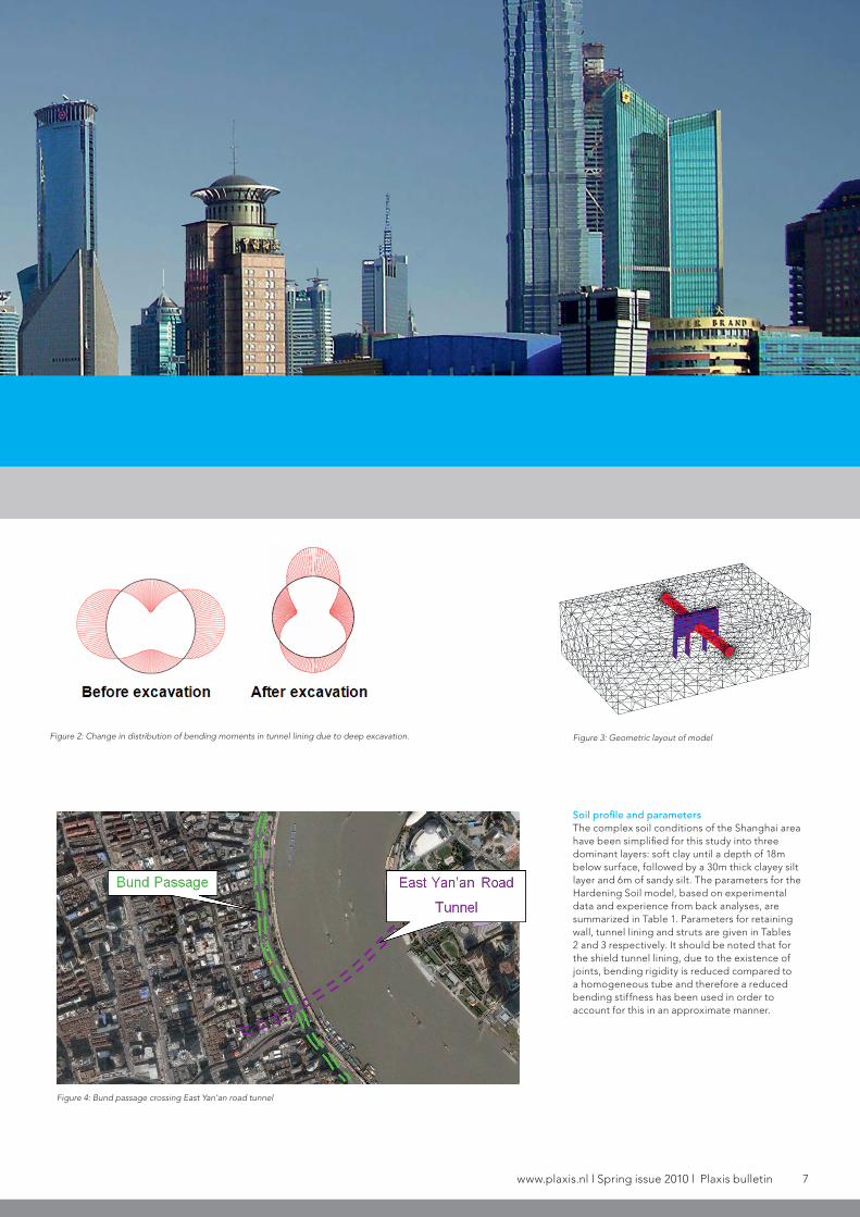
one of the investigated layouts, the corresponding finite element mesh consists of about 90 000 10-nodes tetrahedral elements. The dimensions are 230×150×64m. Lateral boundaries are fixed in horizontal direction and the bottom boundary in vertical and horizontal directions.
Figure 3 resembles the situation at the passage for the East Yan’an Road Tunnel located at the Shanghai Bund (Figure 4) with a tunnel diameter of 11m and therefore results will be presented for this case first. The influence of changing the distance between excavation level and tunnel is also presented in the following because it is the objective of this study to look at different scenarios and not only analyse the project at the Shanghai Bund. In addition, results from another configuration, namely where the deep excavation is located in some lateral distance to the tunnel are presented because these are possible scenarios for other projects in the Shanghai
area. It is noted that the diaphragm walls are very deep. The reason is that these walls are part of the countermeasures to cope with the uplift problem in long term conditions at this particular project. However, in a further series of analyses other configurations with shorter walls will be investigated. As the main purpose of the analysis is the assessment of the influence of the deep excavation on the tunnel, tunnel construction has not been modelled in detail but the tunnel was assumed to be wished-in-place. However, the excavation was modelled in steps. Dewatering and struts were applied before soil excavation in each excavation layer, which is common practice for deep excavations in the Shanghai area.
Study on influence of deep excavations on existing tunnels using PLAXIS-GiD
» In this contribution some results from a comprehensive study investigating different
geometric layouts are presented employing PLAXIS-GiD. As ground conditions in Shanghai are very challenging due to the presence of up to 60m thick layers of very soft soils advanced constitutive models have to be used to obtain reliable results. Based on these studies a better understanding of the interaction of deep excavations and tunnels has been obtained, which could serve as basis for developing appropriate counter measures to avoid damage on existing structures.
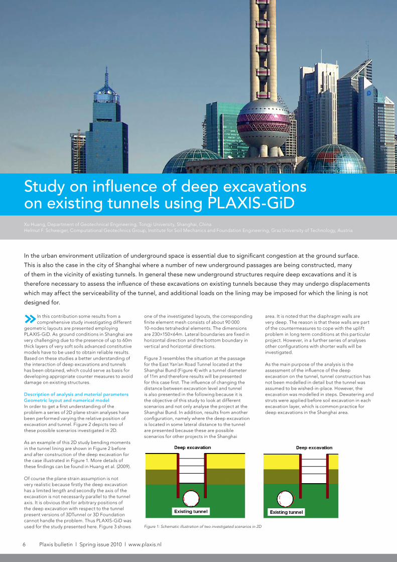
Description of analysis and material parametersGeometric layout and numerical modelIn order to get a first understanding of the problem a series of 2D plane strain analyses have been performed varying the relative position of excavation and tunnel. Figure 2 depicts two of these possible scenarios investigated in 2D.
As an example of this 2D study bending moments in the tunnel lining are shown in Figure 2 before and after construction of the deep excavation for the case illustrated in Figure 1. More details of these findings can be found in Huang et al. (2009).
Of course the plane strain assumption is not very realistic because firstly the deep excavation has a limited length and secondly the axis of the excavation is not necessarily parallel to the tunnel axis. It is obvious that for arbitrary positions of the deep excavation with respect to the tunnel present versions of 3DTunnel or 3D Foundation cannot handle the problem. Thus PLAXIS-GiD was used for the study presented here. Figure 3 shows
In the urban environment utilization of underground space is essential due to significant congestion at the ground surface.
This is also the case in the city of Shanghai where a number of new underground passages are being constructed, many
of them in the vicinity of existing tunnels. In general these new underground structures require deep excavations and it is
therefore necessary to assess the influence of these excavations on existing tunnels because they may undergo displacements
which may affect the serviceability of the tunnel, and additional loads on the lining may be imposed for which the lining is not
designed for.
Xu Huang, Department of Geotechnical Engineering, Tongji University, Shanghai, ChinaHelmut F. Schweiger, Computational Geotechnics Group, Institute for Soil Mechanics and Foundation Engineering, Graz University of Technology, Austria
Figure 1: Schematic illustration of two investigated scenarios in 2D
www.plaxis.nl l Spring issue 2010 l Plaxis bulletin 7
Soil profile and parametersThe complex soil conditions of the Shanghai area have been simplified for this study into three dominant layers: soft clay until a depth of 18m below surface, followed by a 30m thick clayey silt layer and 6m of sandy silt. The parameters for the Hardening Soil model, based on experimental data and experience from back analyses, are summarized in Table 1. Parameters for retaining wall, tunnel lining and struts are given in Tables 2 and 3 respectively. It should be noted that for the shield tunnel lining, due to the existence of joints, bending rigidity is reduced compared to a homogeneous tube and therefore a reduced bending stiffness has been used in order to account for this in an approximate manner.
Figure 3: Geometric layout of model
Figure 4: Bund passage crossing East Yan’an road tunnel
Figure 2: Change in distribution of bending moments in tunnel lining due to deep excavation.
8 Plaxis bulletin l Spring issue 2010 l www.plaxis.nl
Plaxis Practice: Study on influence of deep excavations on existing tunnels using PLAXIS-GID
ConclusionsSome selected results from a comprehensive study investigating the effects of deep excavations on existing tunnels when constructed in their immediate neighbourhood have been presented. PLAXIS-GiD has been used because some of the geometric layouts to be investigated require a 3D representation which cannot be accomplished with 3DFoundation or 3DTunnel.
The results clearly indicate that for situations where the excavation is located directly above the tunnel, deformation of the tunnel will occur and additional forces are introduced into the lining. However, when the excavation is moved to the side of the tunnel, the influence on the tunnel is not significant, at least not for the considered layout, where the diaphragm walls supporting the deep excavation are constructed to the level of the tunnel providing a “shielding effect”.
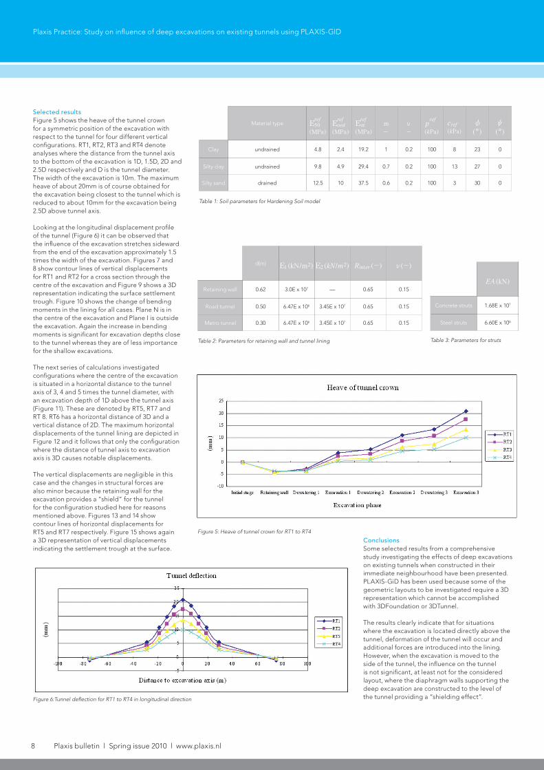
Selected resultsFigure 5 shows the heave of the tunnel crown for a symmetric position of the excavation with respect to the tunnel for four different vertical configurations. RT1, RT2, RT3 and RT4 denote analyses where the distance from the tunnel axis to the bottom of the excavation is 1D, 1.5D, 2D and 2.5D respectively and D is the tunnel diameter. The width of the excavation is 10m. The maximum heave of about 20mm is of course obtained for the excavation being closest to the tunnel which is reduced to about 10mm for the excavation being 2.5D above tunnel axis.
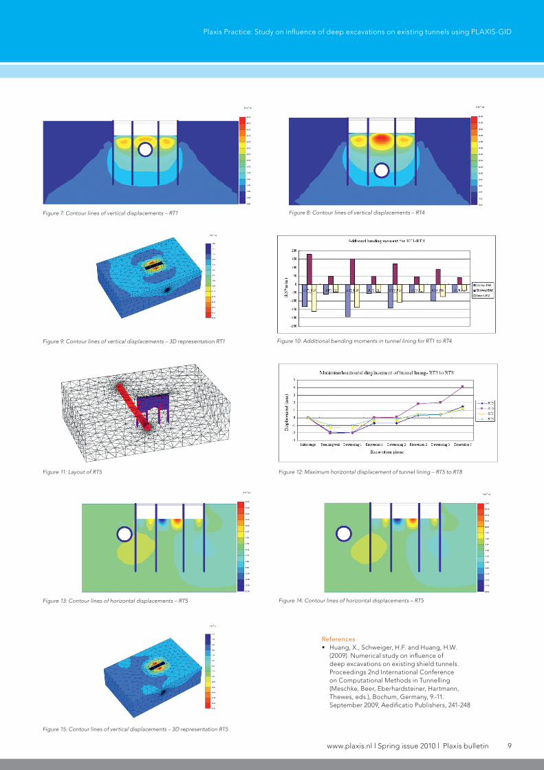
Looking at the longitudinal displacement profile of the tunnel (Figure 6) it can be observed that the influence of the excavation stretches sideward from the end of the excavation approximately 1.5 times the width of the excavation. Figures 7 and 8 show contour lines of vertical displacements for RT1 and RT2 for a cross section through the centre of the excavation and Figure 9 shows a 3D representation indicating the surface settlement trough. Figure 10 shows the change of bending moments in the lining for all cases. Plane N is in the centre of the excavation and Plane I is outside the excavation. Again the increase in bending moments is significant for excavation depths close to the tunnel whereas they are of less importance for the shallow excavations.
The next series of calculations investigated configurations where the centre of the excavation is situated in a horizontal distance to the tunnel axis of 3, 4 and 5 times the tunnel diameter, with an excavation depth of 1D above the tunnel axis (Figure 11). These are denoted by RT5, RT7 and RT 8. RT6 has a horizontal distance of 3D and a vertical distance of 2D. The maximum horizontal displacements of the tunnel lining are depicted in Figure 12 and it follows that only the configuration where the distance of tunnel axis to excavation axis is 3D causes notable displacements.
The vertical displacements are negligible in this case and the changes in structural forces are also minor because the retaining wall for the excavation provides a “shield” for the tunnel for the configuration studied here for reasons mentioned above. Figures 13 and 14 show contour lines of horizontal displacements for RT5 and RT7 respectively. Figure 15 shows again a 3D representation of vertical displacements indicating the settlement trough at the surface.
Load Case Material type
( )MPa
ref50E
( )MPaoedrefE
( )MPaurrefE
-
m
-
o
( )Pak
pref
( )Pak
cref( )cz
( )c}
Clay undrained 4.8 2.4 19.2 1 0.2 100 8 23 0
Silty clay undrained 9.8 4.9 29.4 0.7 0.2 100 13 27 0
Silty sand drained 12.5 10 37.5 0.6 0.2 100 3 30 0
Load Case d(m) (kN/m )1E 2 ( / )kN m2E 2 ( )Rinter - ( )o -
Retaining wall 0.62 3.0E x 107 — 0.65 0.15
Road tunnel 0.50 6.47E x 106 3.45E x 107 0.65 0.15
Metro tunnel 0.30 6.47E x 106 3.45E x 107 0.65 0.15
Load Case (kN)EA
Concrete struts 1.68E x 107
Steel struts 6.60E x 106
Table 1: Soil parameters for Hardening Soil model
Table 2: Parameters for retaining wall and tunnel lining Table 3: Parameters for struts
Figure 5: Heave of tunnel crown for RT1 to RT4
Figure 6:Tunnel deflection for RT1 to RT4 in longitudinal direction
www.plaxis.nl l Spring issue 2010 l Plaxis bulletin 9
Plaxis Practice: Study on influence of deep excavations on existing tunnels using PLAXIS-GID
References• Huang, X., Schweiger, H.F. and Huang, H.W.
(2009). Numerical study on influence of deep excavations on existing shield tunnels. Proceedings 2nd International Conference on Computational Methods in Tunnelling (Meschke, Beer, Eberhardsteiner, Hartmann, Thewes, eds.), Bochum, Germany, 9.-11. September 2009, Aedificatio Publishers, 241-248
Figure 7: Contour lines of vertical displacements – RT1
Figure 9: Contour lines of vertical displacements – 3D representation RT1
Figure 11: Layout of RT5
Figure 13: Contour lines of horizontal displacements – RT5
Figure 15: Contour lines of vertical displacements – 3D representation RT5
Figure 14: Contour lines of horizontal displacements – RT5
Figure 12: Maximum horizontal displacement of tunnel lining – RT5 to RT8
Figure 8: Contour lines of vertical displacements – RT4
Figure 10: Additional bending moments in tunnel lining for RT1 to RT4Table 3: Parameters for struts