study on the online testing technology of oilfield
TRANSCRIPT

Study on the Online Testing Technology of
Oilfield Distribution Transformer Loss Sun Dong
1
Technical Inspection Center of Shengli Petroleum
Administration Bureau
Dongying, Shandong Province, China
E-mail: [email protected]
Bai Jinqiang2
China University of Petroleum(East China)
Qingdao, Shandong Province, China
E-mail: [email protected]
Li Wei3
Technical Inspection Center of Shengli Petroleum
Administration Bureau
Dongying, Shandong Province, China
E-mail:
Fan Lu4
Technical Inspection Center of Shengli Petroleum
Administration Bureau
Dongying, Shandong Province, China
E-mail:
Abstract— At present, there are many different
kinds of transformers in the oilfield, How to identify the
high loss transformer, realize the transformer economic
operation, which has important significance in saving
electricity and reducing oilfield enterprises operating
cost. This paper expounds the on-line measurement
principles of the transformer loss, and according to the
characteristics of the oilfield distribution transformer,
designs the transformer loss online testing system,
which can synchronously acquire the voltage, current
signal of the transformer original and secondary side,
and achieve the on-line transformer loss measuring.
Field tests show that the test system proposed in this
paper, can on-line analysis transformer loss, and
analysis the change of the transformer loss in the
situation of pumping unit generating electricity,
harmonic interference and fluctuation of load. This
research will provide technical support for oilfield
enterprises to identify the high loss transformer and
reasonably select energy-saving transformer, thus
achieve the goal of saving energy and reducing
consumption.
Keywords—transformer loss; online testing;
Rogowski coil; pumping unit; energy-saving
I. INTRODUCTION
Oilfield distribution network has the characteristics
of large scale, much equipment, complicated structure
and low load rate, in the operation and management,
due to laying particular stress on reliability but
despising economy, electricity losses are very serious
[1]. With the particularity of oilfield production,
distribution transformer has a serious phenomenon
that we said "big Mara trolleys", thus the distribution
transformer losses account for a large percentage [2-3].
According to statistics, distribution transformer loss is
about 30~50 TW ∙ h per year, accounts for about
3%~4% of the total generating capacity [4]. Electric
energy waste is huge, and some of the transformer
with parameters aging, higher losses, more defects
and poor reliability, has a serious threat to the safe
operation of power grid. Therefore, it has great
significance to reduce the loss of distribution
transformer and improve the efficiency of the
transformer, both in implementing the strategy of low
cost of oilfield [5] and in alleviating the power
shortage.
In order to reduce the transformer losses, we must
have the corresponding transformer loss testing
technique and means. Now, the main transformer loss
measurement is through the offline no-load and
short-circuit test [6], which can more easily measure
the new transformer. However, for the transformer
which is in operation, if removed, there will not only
waste a lot of manpower and material resources, but
also affect the continuity of power supply and the
normal production of oilfield, there are a lot of
disadvantages. In view of this situation, a new online
testing system of transformer loss is proposed in this
paper, which can acquire the transformer input
electrical parameters, and synchronously acquire the
output electrical parameters. Through the comparison
and analysis of input and output electrical parameters
of transformer, the loss of transformer can be
calculated. This system breaks through the theoretical
calculation method of transformer loss, can online
monitor the transformer loss in the situation of
pumping unit generating electricity, load fluctuations
and harmonic interference, can predict transformer
faults, and has great significance in eliminating high
loss transformer.
II. THE TECHNICAL DIFFICULTIES OF ONLINE
TRANSFORMER LOSS TESTING
A. Oilfield Pumping Unit Load Variety
The working characteristic of pumping unit is
overloaded start and alternating load running [7]. The
pumping unit load is pulse load, the curve of pumping
unit load torque and power is shown in Fig. 1. In the
power generation process of pumping unit, the output
power and time varies with the actual working
condition [8]. For this type distribution transformer
loss measurement, the online testing instrument needs
© 2014. The authors - Published by Atlantis Press 107
International Conference on Mechatronics, Control and Electronic Engineering (MCE 2014)

wide measurement range and fast response speed, so
as to adapt to the characteristics of the pumping unit
load.
Figure 1. The torque and power curve of pumping unit
load
B. Lack of High Voltage Testing Techniques
On the market, low voltage (<600V) testing
instruments and techniques have been relatively
mature, but the testing instrument for 6/10 KV is quite
scarce. Distribution transformer input side has high
voltage but small current, in order to avoid the
traditional voltage sensor magnetic saturation, the
transformer range must be wide, as a result the
transformer volume will be increased, it is not suitable
for transformer online test. The measurement
accuracy of current sensor must be ensured, the
electrical isolation and dielectric strength will be
faced with a major test, and most of the distribution
transformers are overhead, which is not suitable for
measuring. Therefore, in order to online test
transformer loss, mature testing technology and
equipments are needed, based on this situation, this
paper chooses the appropriate method of online
testing, the details see Section 3.
C. Various Transformer Loads
Oilfield power load mainly include periodic
pumping unit load, continuous water pump and oil
pump load and three-phase unbalanced lighting
load[9]. These loads are dispersed in oil wells, petrol
station and depot. Because these are dispersed in so
many spots, too long lines and quite wide area, there
will spend a lot of manpower and material resources
on testing their distribution transformers. Oilfield
distribution transformer load could be one of the
above three kinds of load, or several. A transformer
can supply power to multiple devices which is in the
same type load, or a device needs many transformers
for its power supply. Power distribution network is so
complicated that it is difficult to guarantee the testing
synchronicity.
III. THE ONLINE TESTING PRINCIPLE OF
TRANSFORMER LOSS AND SYSTEM DESIGN
A. The Online Detection Method of TransformerLoss
Transformer equivalent circuit is often used for
related research, now the single phase double winding
transformer is took as the research object, its transient
equivalent circuit [10-11] is shown in Fig. 2.
Figure 2. The transformer transient equivalent circuit
As is shown in Fig. 2, 1r 、 1x is primary winding
resistance, reactance. 21r 、 21x is the primary
winding equivalent value of secondary winding
resistance, reactance. mr 、 mx is the excitation
resistance, reactance. 1u 、 1i is the instantaneous
voltage, current value in the primary side. 2u 、 2i
is the instantaneous voltage, current value in the
secondary side. 21u 、 21i is the primary equivalent
value of secondary instantaneous voltage, current.
mi is the excitation current. k is the ratio. The RMS
value of voltage, current and power can be expressed
as:
T
dttuT
U0
2 )(1
T
dttiT
I0
2 )(1
TT
dttituT
dttpT
P00
)()(1
)(1
Depending on the equivalent circuit, we can get:
T
dtiuT
P0 111
1
T
dtiuT
P0 222
1
1P -input power, 2P -output power.
The total losses of transformer:
TT
dtiuT
dtiuT
PPP0 220 1121
11
PPdtuk
ui
Tdt
k
iiu
T
TT 0 2
120
211 )(
1)(
1
Among them:
T
dtk
iiu
TP
02
11 )(1
T
dtuk
ui
TP
0 21
2 )(1
With load, the voltage drop of the transformer
primary winding leakage resistance is just a few
percent of the rated voltage, and the excitation current
is far less than rated current, is about 3% to 8% of
rated current, large transformer even less than 1%, so
deriving from (4), we can get [5]:
108
FeT
mT
PdtiuT
dtiiuT
P 0 10 2111
1)(
1
CuTT
PdtuuiT
dtkuuk
i
TP
0 211210 212 )(
1)(
1
For single-phase transformer, the actual operational
iron losses FeP and copper loss CuP can be expressed
as:
T
Fe dtk
iiu
TP
02
11 )(1
T
Cu dtuk
ui
TP
0 21
2 )(1
Distribution transformer mainly include Y-yn0 and
D-yn11 connection three-phase oil-immersed type and
dry type transformer, the two types of distribution
transformer loss on-line detection methods are
analyzed as fellows.
Y-yn0 connection distribution transformer wiring
diagram is shown in Fig. 3.
Figure 3. Y-yn0 connection distribution transformer
wiring diagram
The total losses can be deduced according to (3):
T
aA
aT a
AA dtuk
ui
Tdt
k
iiu
TP
00)(
1)(
1
T
bB
bT b
BB dtuk
ui
Tdt
k
iiu
T00
)(1
)(1
CuFeT
cC
cT c
CC PPdtuk
ui
Tdt
k
iiu
T
00)(
1)(
1 (7)
The transformer copper loss and iron loss can be
represented as:
T c
CCb
BBa
AAFe dtk
iiu
k
iiu
k
iiu
TP
0)]()()([
1
T
cC
cbB
baA
aCu dtuk
uiu
k
uiu
k
ui
TP
0)]()()([
1
Each phase voltage and current of Y-yn0
connection transformer can be directly measured, and
transformer iron loss and copper loss can be
calculated by (8). But for D-yn11 connection
transformer, as shown in Fig. 4, the original edge
phase current cannot be directly measured, the
measured line current is needed to be converted into
phase current, then can be calculated by (8).
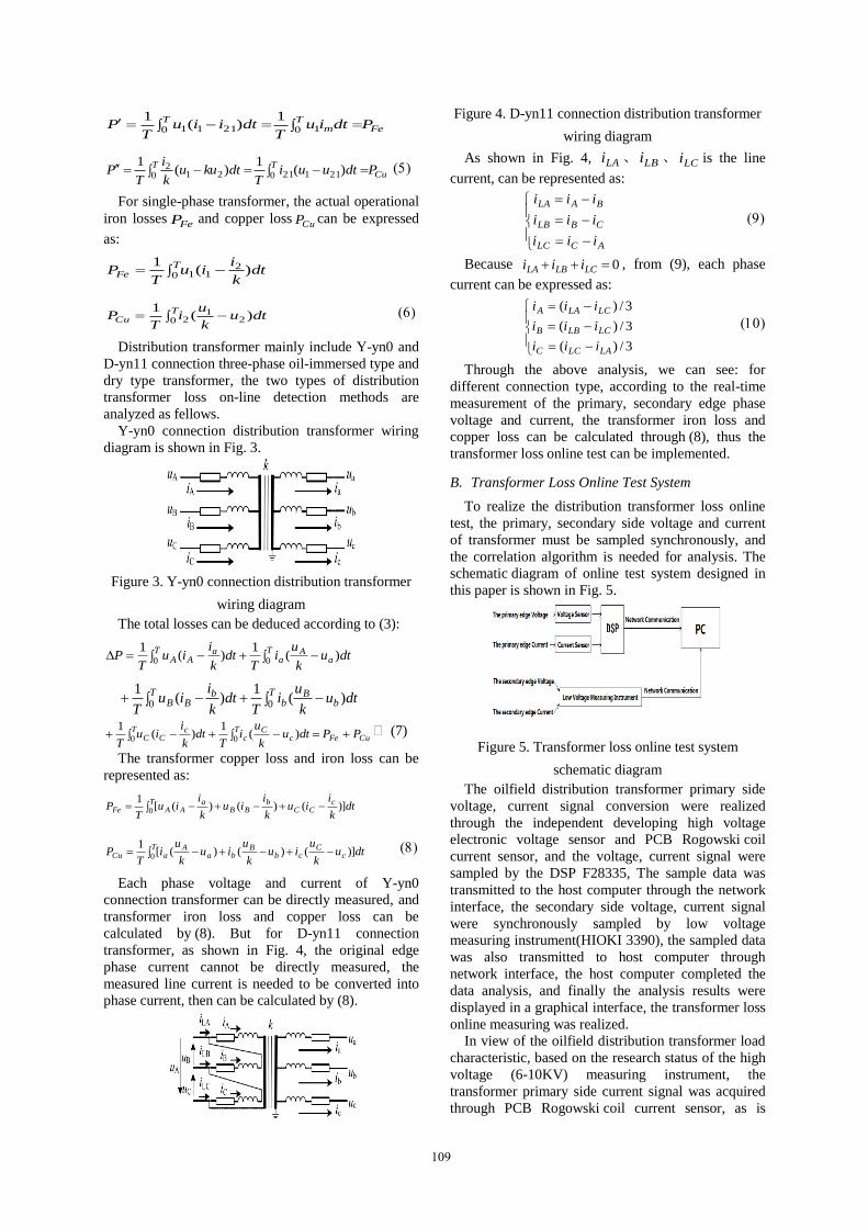
Figure 4. D-yn11 connection distribution transformer
wiring diagram
As shown in Fig. 4, LAi 、 LBi 、 LCi is the line
current, can be represented as:
ACLC
CBLB
BALA
iii
iii
iii
Because 0 LCLBLA iii , from (9), each phase
current can be expressed as:
3/)(
3/)(
3/)(
LALCC
LCLBB
LCLAA
iii
iii
iii
Through the above analysis, we can see: for
different connection type, according to the real-time
measurement of the primary, secondary edge phase
voltage and current, the transformer iron loss and
copper loss can be calculated through (8), thus the
transformer loss online test can be implemented.
B. Transformer Loss Online Test System
To realize the distribution transformer loss online
test, the primary, secondary side voltage and current
of transformer must be sampled synchronously, and
the correlation algorithm is needed for analysis. The
schematic diagram of online test system designed in
this paper is shown in Fig. 5.
Figure 5. Transformer loss online test system
schematic diagram
The oilfield distribution transformer primary side
voltage, current signal conversion were realized
through the independent developing high voltage
electronic voltage sensor and PCB Rogowski coil
current sensor, and the voltage, current signal were
sampled by the DSP F28335, The sample data was
transmitted to the host computer through the network
interface, the secondary side voltage, current signal
were synchronously sampled by low voltage
measuring instrument(HIOKI 3390), the sampled data
was also transmitted to host computer through
network interface, the host computer completed the
data analysis, and finally the analysis results were
displayed in a graphical interface, the transformer loss
online measuring was realized.
In view of the oilfield distribution transformer load
characteristic, based on the research status of the high
voltage (6-10KV) measuring instrument, the
transformer primary side current signal was acquired
through PCB Rogowski coil current sensor, as is
109

shown in Fig. 6, which is first proposed in this paper.
Host computer control and data processing analysis
software was independent developed. The transformer
primary side self-developed test system and secondary
side low voltage measuring instrument (HIOKI 3390)
were controlled by host computer through the network
interface, the transformer primary and secondary side
electrical parameters synchronous sample was
realized, thus the transformer losses were acquired.
Figure 6. PCB Rogowski coil current sensor photo
IV. FIELD DATA ANALYSIS
With the transformer loss test system designed in
this paper, distribution transformer losses in the
situation of load fluctuation, harmonic interference
and pumping unit generating electricity were tested
and analyzed in ShengLi oilfield.
Case 1: The impact of load fluctuations on the
transformer loss
The distribution transformer of pumping unit load,
electric submersible pump load were measured, test
data are shown in TABLE I. C44-P6 well distribution
transformer load is electric submersible pump load,
C45-P1 distribution transformer load is well pumping
unit load. The active power test waveform of
distribution transformer with pumping unit load is
shown in Fig. 7, and the electric submersible pump
load is shown in Fig. 8.
Figure 7. The active power test waveform of
distribution transformer with pumping unit load
Figure 8. The active power test waveform of
distribution transformer with electric submersible
pump load
TABLE I. THE TRANSFORMER TEST DATA UNDER DIFFERENT
LOAD
From Fig. 7 and 8, we can see that pumping unit
load is periodical alternating load, fluctuation is
bigger than electric submersible pump load. By
comparison in TABLE I, we can see that the
distribution transformer efficiency of pumping unit is
only 89.59%, but the distribution transformer
efficiency of electric submersible pump reached
97.71%, the losses are relatively smaller than the
pumping unit. From this, we conclude that load
fluctuation has direct influence to the loss of
transformer, for variable load conditions, such as
pumping unit load, the relevant formula in the
standard "power transformer economical operation
(GB/T 13462-2008)" cannot be applied to estimate the
losses of transformer.
Case 2: The impact of pumping unit generating
electricity on the transformer loss
A certain "one with two" system distribution
transformer was tested, which is a transformer supply
for two pumping unit, the test data are shown in
TABLE II. The transformer primary side active power
and the C93 - P1 well, C45 - P13 well control cabinet
input active power test waveform is shown in Fig. 9.
Figure 9. The active power test waveform
TABLE II. A CERTAIN "ONE WITH TWO" SYSTEM DISTRIBUTION
TRANSFORMER TEST DATA
Well No.
Mean Active
Power(kw)
Mean Negative
Power(kw) Losses
(kw)
Efficiency
Ratio(%)
Primary Secondary Primary Secondary
C93-P1 19.57
7.27 -1.33
-2.29 2.08 89.37%
C45-P13 10.22 -1.89
From Fig. 9, we can see that the two pumping unit
have negative power, that is "generating electricity"
phenomenon. TABLE II shows that the average
negative power of C93-P1 well, C45-P13 well is -2.29
Well
No.
Active Power(kw) Losses
(kw)
Efficiency
Ratio(%) Notes
Primary Secondary
C44-P6 59.79 58.42 1.37 97.71 Submersible
pump
C45-P1 8.07 7.23 0.84 89.59 Pumping unit
110

kW and -1.89 kW, but the distribution transformer
primary side average negative power is -1.33 kW.
From this, we can see that pumping unit system can
release electricity to the grid, the transformer loss
increases, transformer efficiency decrease, but there is
no relevant standard to measure or evaluate this
feedback electricity, and the influence to the
transformer loss cannot be calculated.
Case 3: The impact of harmonic interference on the
transformer loss
A one DC generatrix "one with five" system
distribution transformer was tested, that is the
alternating current through the transformer, then
through AC/DC transform, was transformed into DC
current, and it was transferred to each wells through
DC generatrix. At the power distribution cabinet, the
DC current was transformed into alternating current
through DC/AC transform, then supply for pumping
unit motor. The tested transformer supplies for five
belt type pumping unit, the test data is shown in
TABLE III. The transformer primary side voltage,
current and active power test waveform is shown in
Fig. 10. The transformer voltage and current harmonic
distribution is shown in Fig. 11.
Figure 10. The transformer primary side voltage,
current and active power test waveform
Figure 11. The transformer voltage and current
harmonic distribution
TABLE III. A ONE DC GENERATRIX "ONE WITH FIVE" SYSTEM
DISTRIBUTION TRANSFORMER TEST DATA
Well No. Active Power(kw) Losses
(kw)
Efficiency
Ratio(%) Primary Secondary
C45-P8
16.53
2.57
1.47 91.11%
C45-P10 3.72
C45-P7 2.64
C45-P4 3.45
C71-P14 2.68
From Fig. 10, we can see that due to rectifier and
inverter technology, transformer primary side current
has a certain degree of distortion-double peak. From
Fig. 11, we can see that 5 and 7 times harmonic in
current is more than others. TABLE III shows the
transformer efficiency decreases, loss increases
relatively. According to the testing data, its current
harmonic content has reached the 6KV power
harmonic content that standard "GB/T14549-1993
utility grid harmonic "stipulated. There is also no
specific theoretical formula for calculating their
impact on the transformer loss.
V. CONCLUSION
The field experiments show that the impact of the
load fluctuation, pumping unit generating power and
harmonic interference on the transformer loss cannot
be calculated through clear theoretical formula at
present. However, the oilfield distribution transformer
can be online tested by the testing system which is
designed in this paper, which can effectively analyze
the transformer operating loss. It has important
engineering significance in identifying the high loss of
transformer in different working conditions, and
provides technical support for saving energy and
reducing consumption in oilfield.
REFERENCES
[1] Chen Shuhua. Research on 10KV Power Saving Energy and Reducing Consumption. Technology and Business, 2012(11): 166.
[2] Chen Guocheng, Dai Chaoren. The Energy Saving Operation of the Oil Bump Transformer by Means of Adjustable Capacity. Transformer, 1997, 34(8): 35-36.
[3] Li Jiandong, Yuan Fengjun, Deng Ping. The Application of Energy-intensive Transformer Energy-saving Technology in Gudao Oil Production Plant. Electrical Applications, 2011,30 (23): 52-54, 84.
[4] Hao Lingxia. The Loss Analysis of Distribution Transformer and Loss Reduction Measures. Power Supply Technologies and Application, 2012 (12):97-98.
[5] Wu Xihong. Research on the Online Detection Method for the Loss and Capacity of Distribution Transformer. Chongqing University, 2010.
[6] He Wei, Wu Xihong, Wang Ke, etc. Online Detecting Method of Transformer Open-circuit Loss and Short-circuit Loss. Proceedings of the CSU-EPSA, 2010, 22(6): 72-76.
[7] Zheng Yuming. The Development of the Oilfield Special Adjustable Capacity Transformer. OGSE, 2000, 19 (4):53-54.
[8] Zhang Xiaoning, Zhang Baogui, Lu Zeyin, etc. Research and Application of Reactive Power Compensation of Distribution System for Oil-pumping Units. Electric Power Automation Equipment, 2004, 24(4): 57-60.
[9] Shang Debin. Analysis of Oil Pumping Load Peculiarity of ZhongYuan Oilfield and Study of Reactive Power Compensation. China University of Petroleum (East China),2009.
[10] Cheng Lin. Research on Power Transformer Online Testing. Huazhong University of Science and Technology, 2006.
[11] Arri E, Carta A, Mocci F, Tosi M. Diagnosis of the state of power transformer windings by on-line measurement of stray reactance. IEEE Transactions On Instrumentation and Measurement, 1993, 42(2):372—378.
111