study regarding the design of a special · pdf filethe behaviour of piles with large diameter...
TRANSCRIPT
BULETINUL INSTITUTULUI POLITEHNIC DIN IAŞI Publicat de
Universitatea Tehnică „Gheorghe Asachi” din Iaşi Tomul LVIII (LXII), Fasc. 4, 2012
Secţia CONSTRUCŢII. ARHITECTURĂ
STUDY REGARDING THE DESIGN OF A SPECIAL FOUNDATION SYSTEM SLAB ON COLUMNS
BY
ALEXANDRA-ALISA GĂINĂ*, ANDREI ILAŞ and ANA NICUŢĂ
“Gheorghe Asachi” Technical University of Iaşi Faculty of Civil Engineering and Building Services
Received: September 5, 2012 Accepted for publication: September 30, 2012
Abstract. The aim of this paper is to analyse a colums raft foundation
system. The soil, on which it is located the structure, belongs to difficult foundation earth and is characterized by a contractile clay with the presence of underground water. Using geotechnical calculation programs has been evaluated the behaviour of piles with large diameter (columns) based on three modelling types of slab design and considering loaded only with axial force, because, especially in this case, the foundation have to ensure safety for entire building. We analyse a single column with the bigger load provided from the slab, proposing also a reinforcement solution. The interest for analysing the columns is to know that the interaction between foundation system and foundation environment is very important. To accomplish these conditions mentioned before it is necessary to ensure the column strength. This research also wants to determine the quantity of materials (concrete and steel) in columns. The final task of the analyse is to design a resistance and safety foundation system.
Key words: columns raft; settlement; contractil soil; reinforcement; foundation system.
*Corresponding author: e-mail: [email protected]

54 Alexandra-Alisa Găină, Andrei Ilaş and Ana Nicuţă
1. Introduction
It is known that because of building agglomeration in towns and due to
current tendency of improving the urban appearance in cityes is required to build high constructions. Nowadays, the locations on which we can place a building are characterised, in general, by a difficult terrain foundation. This fact impose special conditions in designing a safety foundation system.
It is necessary to take into consideration that our country has a seismically active area so, in designing a foundation system we must take safety measures.
This paper analyses a piled raft foundation in order to see which is the behavior and the more rational use of materials from different types of slab loaded only with axial force.
2. General Data of Foundation and Site
The level of the underground water is 6.00 m in depth of the natural level of ground.
Columns goes through two types of earth. The first type (fat clay) appears in natural and saturated state.
Columns are embedded in last type (marly clay, in saturated state) on a 2.5 diameters depth.
Stratification characteristics of first and second layer are presented in Tables 1 and 2.
Table 1 Properties of Fat Clay
w, [%]
wp, [%]
wL , [%]
Sr Particle size, [%]
C M S 23.0 22.0 63.0 0.96 83.0 17.0 0.0
Ip , [%] Ic , [%] n, [%] e γ, [%] γd , [%] γsat , [%] 41.0 0.98 37.0 0.6 20.3 16.7 20.54
1 3nM , [kPa] 2 3
nM , [kPa] 2np , [kPa] 1 3
iM , [kPa] 2 3iM , [kPa] 2
ip , [kPa] k, [kN/m3]
9,756 10,000 2.4 5,714 6,897 4.4 80,000 Es , [kN/m2] Ws , [kN/m2] Φ’, [°] c′, [kN/m2] Φuu , [°] cuu , [kN/m2] ν
12,600 37,800 16.0 41.0 25.0 82.0 0.42 Note: C – clay; M – silt; S – sand; n – natural characteristics state; i – saturated characteristics state.

Bul. Inst. Polit. Iaşi, t. LVIII (LXII), f. 4, 2012 55
Table 2 Properties of Marly Clay
w, [%]
wp, [%]
wL , [%]
Sr Particle size, [%]
C M S 16.91 20.0 60.0 1.0 61.0 36.0 3.0 Ip , [%] Ic , [%] n, [%] e γ [%] γd , [%] γsat , [%] 39.8 1.08 33.8 0.51 21.0 17.6 20.57
1 3nM , [kPa] 2 3
nM , [kPa] 2np , [kPa] 1 3
iM , [kPa] 2 3iM , [kPa] 2
ip , [kPa] k, [kN/m3]
8,772 11,111 4.05 5,479 6,061 5.15 100,000 Es , [kN/m2] Ws , [kN/m2] Φ’, [°] c′, [kN/m2] Φuu , [°] cuu , [kN/m2] ν
8,000 24,000 24.0 42.0 35.0 130.0 0.42 Note: C – clay; M – silt; S – sand; n – natural characteristics state; i – saturated characteristics state.
2.1. Characteristics of Soil
The mechanics characteristics of terrain are calculated according to Romanian design normative NP 126/2008 (Normative for construction founded on earths with swellings and large contractions – PUCM) since 2008, adapted with European standards. Characteristics of site resulted after data processed in laboratory have imposed to make the graphs for granulometry and stamp of earth, presented below according to NP 126/2008:
Fig. 1 – Ternary diagram.
a) Granulometric composition for clay and fat clay is represented in the ternary diagram (Fig. 1).

56 Alexandra-Alisa Găină, Andrei Ilaş and Ana Nicuţă
b) Graphic stamp of fat clay and marly clay (Fig.2).
Fig. 2 – Stamp of fat clay and marly clay.

Bul. Inst. Polit. Iaşi, t. LVIII (LXII), f. 4, 2012 57
2.2. Properties of Earth
Properties of fat clay and marly clay determined in laboratory are presented in Tables 1 and 2.
2.3. Presentation of Construction and the Position on Site
Structural strength of building is formed by three concrete cores connected between them through trusses made from precast concrete. This constructive system does not allow large differentiated settlements between
Fig. 3 – Construction shape.
Fig. 4 – Construction position on site.

58 Alexandra-Alisa Găină, Andrei Ilaş and Ana Nicuţă
foundations because of the connection of precast concrete trusses with monolith reinforced concrete cores. Thereby the building and implicitly the foundation systems of construction are placed on the right and left bank of the river. On the first dimension design has been resulted 25 columns. Therefore is required a more detailed analyse of the adopted foundation made of reinforced concrete composed of a slab on columns symmetrically placed in the slab plane.
2.4. Computation of Piles Foundation System According to
Eurocode 7, case B and C Determination of the calculation value of last bearing capacity to
compression is based on following relations:
Rc,d = Rb,d + Rs,d = b
kbR
, + s
ksR
, , [kN], (1)
where: Rb,d represents the calculation value resistance on the base of pile; Rs,d – calculation value of friction resistance on the lateral surface of the pile; γb – partial coefficient for the resistance on the base of pile; γs – partial coefficient for the resistance friction on the lateral surface of the pile; Rb,k – characteristic value of the resistance on the base of pile; Rs,k – characteristic value of the friction resistance of the lateral surface of the pile; Rb,k = Ab qb,k, [kN], (2) where: Ab is the surface of the pile base;
qb,k = cu
uccN
= cu
uc9 , [kPa], (3)
– characteristic value of the pressure on the base; cuk = 90 + 5z, [kPa], (4) with: cuk – the characteristic value of the undrained cohesion; γcu – partial factor for the undrained cohesion; z – length of pile;
,s ,k si s ,i ,k s ,i ,k iR A q U q l [kN], (5)
where: Asi is the lateral surface of the pile in the i layer; U – the perimeter of the transversal section of pile; qs,i,k – characteristic value of the frictional resistance in the i layer; li – length of pile in contact with i layer.
2.5. Centralization of Results by Calculation Using
Eurocode 7, variant B and C
Variant B determine the bearing capacity which gouvern the structure of column, respectively its reinforcement. Variant C determine the bearing capacity of column by earth resistance (Table 3).

Bul. Inst. Polit. Iaşi, t. LVIII (LXII), f. 4, 2012 59
Table 3 Centralization Results of Calculation Using Eurocode 7 Computational approach B C
γb 1.6 1.6 γs 1.3 1.3 γcu 1.0 1.4
cuk , [kPa] 207.5 207.5 Ab , [m2] 0.916 0.916 U, [m] 3.393 3.393
∑qs,i,kli , [kPa] 1,585.07 1,585.07 qb,k , [kPa] 1,867.50 1,333.93 Rb,k , [kN] 1,710.63 1,221.88 Rs,k , [kN] 5,378.16 5,378.16 Rc,d , [kN] 5,206.19 4,900.72
2.6. Drilling Profile and the Positioning of Slab on Site
The drilling profile is made in Bore, subprogram of the geotechnical
calculation program Geotec Office.
Fig. 5 – Construction position on site.
Drilling is considered in the middle of slab plane, in the right of
thirteenth column (Fig. 9). First layer is represented by fat clay in natural state. The second layer by fat clay in flooded state because of underground water

60 Alexandra-Alisa Găină, Andrei Ilaş and Ana Nicuţă
presence at 6.00 m depth. Third layer is represented by marly clay in flooded state because of water presence.
The drilling is made up to 30.00 m depth of the natural level of site. N o t e. B1 – symbol of drilling profile; TK – high level of slab (is
situated at 1.00 m under the natural level of earth); TF – bottom level of slab (3.5 m under the natural level of earth); GW – symbol of water presence (6.00 m under the natural level of earth).
2.7. Presentation of Foundation System in 3-D View and Position in Plan of Columns on Slab
The foundation system is composed from a slab with square form in plan, with 17.00 m sides and 2.50 m height. Columns have a 24.00 m total length and the free length is 23.50 m. The transversal section of columns is circular and has 1.08 m in diameter.
Columns position on slab is in accordance with the specifications of Eurocode 7. The position of columns presented in Fig. 8 is the same with the current number in Table 4.
Fig. 6 – Construction position
on site.
Fig. 7 – Columns position and numbering on slab.
3. Analysis of Columns Behaviour in Three Types of Slab Modelling
3.1. Analysis of Columns Behavior Considering the Slab
Elastic, Rigid and Flexible In what follows is determined the behavior of columns from the three
modelling of the slab loaded only with axial force. The analysis is made in

Bul. Inst. Polit. Iaşi, t. LVIII (LXII), f. 4, 2012 61
geotechnical calculation program Geotec Office, in layered soil model method. The foundation system is loaded with 65,000 kN.
a) Centralization of data obtained from the geotechnical calculation program Geotec Office
In Table 4 are presented the data obtained (V – load reaction of column, Fr – column load, Sr – settlement) in columns of the three analysis considering the slab elastic, rigid and flexible.
Table 4 Centralization of Data Obtained in Columns from Geotec Office
No.
Elastic slab Rigid slab Flexible slab V
kN Fr kN
Sr cm
V kN
Fr kN
Sr cm
V kN
Fr kN
Sr cm
1 3,377.2 3,363.5 3.87 4,395.0 4,395.0 3.95 5,387.1 5,386.7 4.62 2 3,027.3 3,036.2 4.03 3,425.0 3,425.0 3.95 4,165.5 4,165.3 4.62 3 2,986.7 3,011.8 4.10 3,259.2 3,259.2 3.95 3,957.7 3,957.5 4.62 4 3,017.8 3,060.9 4.04 3,425.5 3,425.5 3.95 4,165.5 4,165.3 4.62 5 3,348.9 3,426.9 3.91 4,396.5 4,396.5 3.95 5,386.9 5,386.7 4.62 6 3,043.4 3,022.9 4.02 3,425.1 3,425.1 3.95 4,165.5 4,165.2 4.62 7 2,702.7 2,703.5 4.20 2,528.7 2,528.7 3.95 3,022.4 3,022.2 4.62 8 2,704.9 2,718.0 4.30 2,383.5 2,383.5 3.95 2,840.2 2,840.0 4.62 9 2,690.9 2,717.1 4.22 2,528.9 2,528.9 3.95 3,022.4 3,022.3 4.62
10 3,005.4 3,061.8 4.04 3,425.4 3,425.4 3.95 4,165.4 4,165.2 4.62 11 3,017.7 2,990.9 4.08 3,259.1 3,259.1 3.95 3,957.7 3,957.5 4.62 12 2,715.8 2,712.2 4.29 2,383.4 2,383.4 3.95 2,840.1 2,840.0 4.62 13 2,853.0 2,861.5 4.43 2,232.3 2,232.3 3.95 2,650.7 2,650.5 4.62 14 2,696.8 2,717.8 4.30 2,383.6 2,383.6 3.95 2,840.2 2,840.0 4.62 15 2,963.5 3,012.0 4.10 3,259.2 3,259.2 3.95 3,957.7 3,957.5 4.62 16 3,065.8 3,031.4 4.02 3,425.5 3,425.5 3.95 4,165.5 4,165.3 4.62 17 2,714.1 2,705.1 4.20 2,528.7 2,528.7 3.95 3,022.5 3,022.3 4.62 18 2,708.5 2,712.4 4.29 2,383.4 2,383.4 3.95 2,840.3 2,840.1 4.62 19 2,686.9 2,703.1 4.20 2,528.8 2,528.8 3.95 3,022.6 3,022.4 4.62 20 2,992.9 3,035.0 4.03 3,425.1 3,425.1 3.95 4,165.6 4,165.3 4.62 21 3,427.4 3,376.0 3.87 4,396.8 4,396.8 3.95 5,386.9 5,386.6 4.62 22 3,053.8 3,031.8 4.02 3,425.5 3,425.5 3.95 4,165.5 4,165.2 4.62 23 2,997.1 2,991.3 4.08 3,259.1 3,259.1 3.95 3,957.7 3,957.5 4.62 24 3,012.1 3,022.4 4.02 3,425.1 3,425.1 3.95 4,165.5 4,165.2 4.62 25 3,323.1 3,360.5 3.87 4,395.0 4,395.0 3.95 5,386.8 5,386.5 4.62
b) Centralization of obtained data Analysis has been made in layered soil model for all types of slab
modelling, under 65,000 kN axial load positioned in the centre (on column number 13) of the foundation system.

62 Alexandra-Alisa Găină, Andrei Ilaş and Ana Nicuţă
In all the analysed slabs cases the most loaded columns (V – load reaction of column and Fr – column load) are those who are in the corners. Settlement (S) is differentiated on columns for slab cases. On the elastic slab the settlement with the biggest value of the slab is in center, on 13th column. In this case the settlement is differentiated on columns and the maximum value is greater than on the rigid slab.
Fig. 8 – System of loading, [kN].
In rigid slab case the columns with values V, Fr are equal and
intermediary between the other two modelling types of slab. Settlement has the same value on all columns and is the smallest of the other two analysis.
In flexible slab case V, Fr and S on the columns are the same as in rigid slab case. The values of V, Fr and S in this case are the biggest as in the other two analysis.
3.2. Graphic Exemplification of Settlement
The graphical representation is different for elastic slab from rigid and flexible slab. This situation is a consequence of the fact that the last two slabs mentioned have the same settlement across the entire foundation system.
Fig. 9 – Settlement representation for elastic slab, [cm].

Bul. Inst. Polit. Iaşi, t. LVIII (LXII), f. 4, 2012 63
Fig. 10 – Settlement representation for rigid slab, [cm].
Fig. 11 – Settlement representation for flexible slab, [cm].
64 Alexandra-Alisa Găină, Andrei Ilaş and Ana Nicuţă
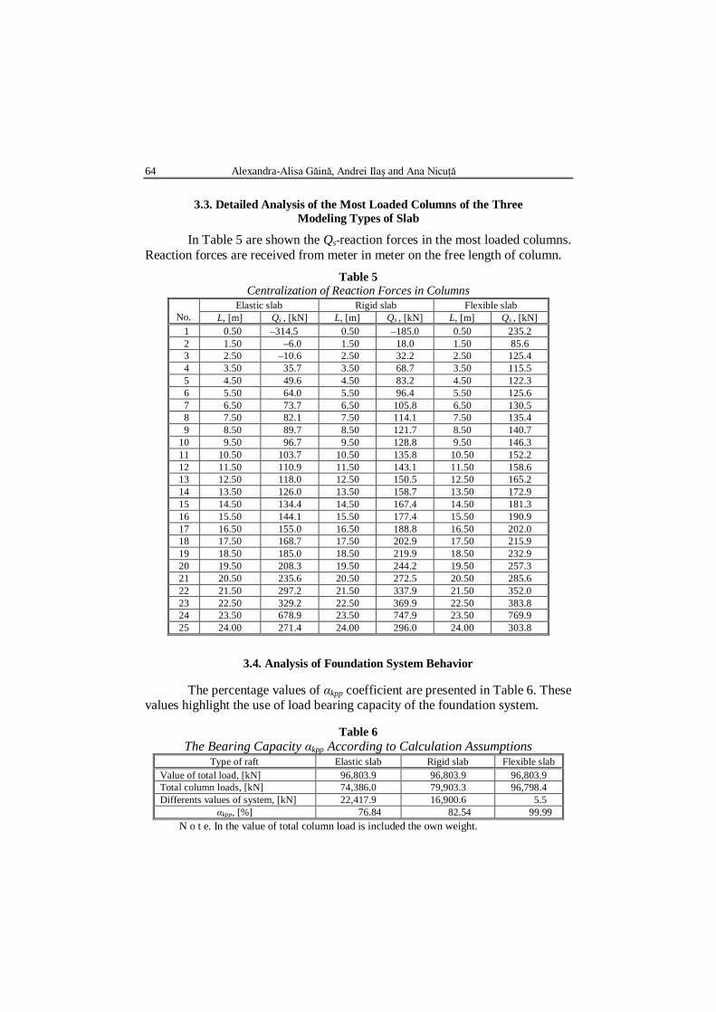
3.3. Detailed Analysis of the Most Loaded Columns of the Three
Modeling Types of Slab
In Table 5 are shown the Qs-reaction forces in the most loaded columns. Reaction forces are received from meter in meter on the free length of column.
Table 5 Centralization of Reaction Forces in Columns
No.
Elastic slab Rigid slab Flexible slab L, [m] Qs , [kN] L, [m] Qs , [kN] L, [m] Qs , [kN]
1 0.50 –314.5 0.50 –185.0 0.50 235.2 2 1.50 –6.0 1.50 18.0 1.50 85.6 3 2.50 –10.6 2.50 32.2 2.50 125.4 4 3.50 35.7 3.50 68.7 3.50 115.5 5 4.50 49.6 4.50 83.2 4.50 122.3 6 5.50 64.0 5.50 96.4 5.50 125.6 7 6.50 73.7 6.50 105.8 6.50 130.5 8 7.50 82.1 7.50 114.1 7.50 135.4 9 8.50 89.7 8.50 121.7 8.50 140.7 10 9.50 96.7 9.50 128.8 9.50 146.3 11 10.50 103.7 10.50 135.8 10.50 152.2 12 11.50 110.9 11.50 143.1 11.50 158.6 13 12.50 118.0 12.50 150.5 12.50 165.2 14 13.50 126.0 13.50 158.7 13.50 172.9 15 14.50 134.4 14.50 167.4 14.50 181.3 16 15.50 144.1 15.50 177.4 15.50 190.9 17 16.50 155.0 16.50 188.8 16.50 202.0 18 17.50 168.7 17.50 202.9 17.50 215.9 19 18.50 185.0 18.50 219.9 18.50 232.9 20 19.50 208.3 19.50 244.2 19.50 257.3 21 20.50 235.6 20.50 272.5 20.50 285.6 22 21.50 297.2 21.50 337.9 21.50 352.0 23 22.50 329.2 22.50 369.9 22.50 383.8 24 23.50 678.9 23.50 747.9 23.50 769.9 25 24.00 271.4 24.00 296.0 24.00 303.8
3.4. Analysis of Foundation System Behavior
The percentage values of αkpp coefficient are presented in Table 6. These values highlight the use of load bearing capacity of the foundation system.
Table 6 The Bearing Capacity αkpp According to Calculation Assumptions
Type of raft Elastic slab Rigid slab Flexible slab Value of total load, [kN] 96,803.9 96,803.9 96,803.9 Total column loads, [kN] 74,386.0 79,903.3 96,798.4 Differents values of system, [kN] 22,417.9 16,900.6 5.5
αkpp, [%] 76.84 82.54 99.99 N o t e. In the value of total column load is included the own weight.
Bul. Inst. Polit. Iaşi, t. LVIII (LXII), f. 4, 2012 65
4. Determination of Resistance Reinforcement and the
Behavior of the Columns In what follows is presented the horizontal capacity and the settlements
of columns working in group.
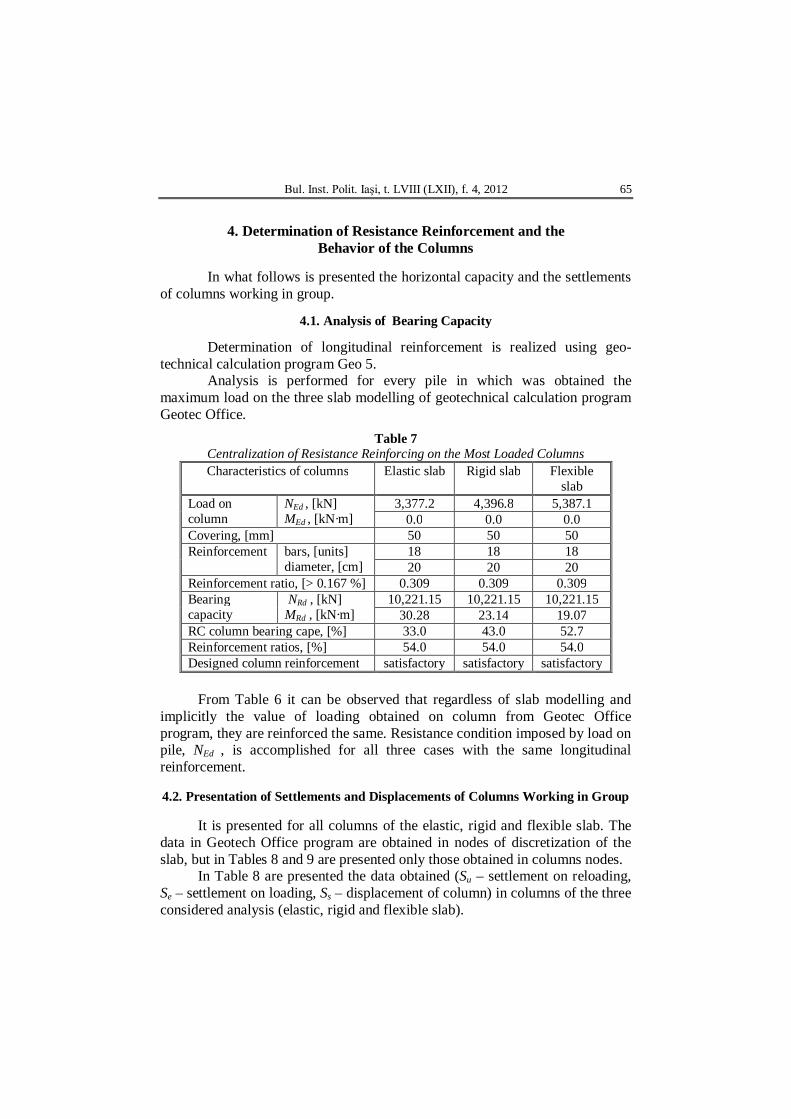
4.1. Analysis of Bearing Capacity
Determination of longitudinal reinforcement is realized using geo-technical calculation program Geo 5.
Analysis is performed for every pile in which was obtained the maximum load on the three slab modelling of geotechnical calculation program Geotec Office.
Table 7 Centralization of Resistance Reinforcing on the Most Loaded Columns Characteristics of columns Elastic slab Rigid slab Flexible
slab Load on column
NEd , [kN] MEd , [kN·m]
3,377.2 4,396.8 5,387.1 0.0 0.0 0.0
Covering, [mm] 50 50 50 Reinforcement bars, [units]
diameter, [cm] 18 18 18 20 20 20
Reinforcement ratio, [> 0.167 %] 0.309 0.309 0.309 Bearing capacity
NRd , [kN] MRd , [kN·m]
10,221.15 10,221.15 10,221.15 30.28 23.14 19.07
RC column bearing cape, [%] 33.0 43.0 52.7 Reinforcement ratios, [%] 54.0 54.0 54.0 Designed column reinforcement satisfactory satisfactory satisfactory
From Table 6 it can be observed that regardless of slab modelling and
implicitly the value of loading obtained on column from Geotec Office program, they are reinforced the same. Resistance condition imposed by load on pile, NEd , is accomplished for all three cases with the same longitudinal reinforcement.
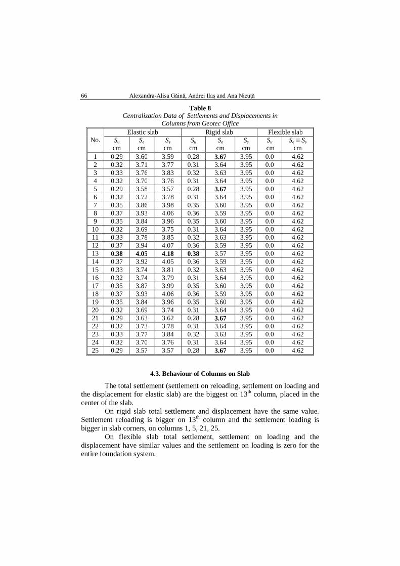
4.2. Presentation of Settlements and Displacements of Columns Working in Group
It is presented for all columns of the elastic, rigid and flexible slab. The data in Geotech Office program are obtained in nodes of discretization of the slab, but in Tables 8 and 9 are presented only those obtained in columns nodes.
In Table 8 are presented the data obtained (Su – settlement on reloading, Se – settlement on loading, Ss – displacement of column) in columns of the three considered analysis (elastic, rigid and flexible slab).
66 Alexandra-Alisa Găină, Andrei Ilaş and Ana Nicuţă
Table 8 Centralization Data of Settlements and Displacements in
Columns from Geotec Office
No. Elastic slab Rigid slab Flexible slab
Su cm
Se cm
Ss cm
Su cm
Se cm
Ss cm
Su cm
Se ≡ Ss cm
1 0.29 3.60 3.59 0.28 3.67 3.95 0.0 4.62 2 0.32 3.71 3.77 0.31 3.64 3.95 0.0 4.62 3 0.33 3.76 3.83 0.32 3.63 3.95 0.0 4.62 4 0.32 3.70 3.76 0.31 3.64 3.95 0.0 4.62 5 0.29 3.58 3.57 0.28 3.67 3.95 0.0 4.62 6 0.32 3.72 3.78 0.31 3.64 3.95 0.0 4.62 7 0.35 3.86 3.98 0.35 3.60 3.95 0.0 4.62 8 0.37 3.93 4.06 0.36 3.59 3.95 0.0 4.62 9 0.35 3.84 3.96 0.35 3.60 3.95 0.0 4.62
10 0.32 3.69 3.75 0.31 3.64 3.95 0.0 4.62 11 0.33 3.78 3.85 0.32 3.63 3.95 0.0 4.62 12 0.37 3.94 4.07 0.36 3.59 3.95 0.0 4.62 13 0.38 4.05 4.18 0.38 3.57 3.95 0.0 4.62 14 0.37 3.92 4.05 0.36 3.59 3.95 0.0 4.62 15 0.33 3.74 3.81 0.32 3.63 3.95 0.0 4.62 16 0.32 3.74 3.79 0.31 3.64 3.95 0.0 4.62 17 0.35 3.87 3.99 0.35 3.60 3.95 0.0 4.62 18 0.37 3.93 4.06 0.36 3.59 3.95 0.0 4.62 19 0.35 3.84 3.96 0.35 3.60 3.95 0.0 4.62 20 0.32 3.69 3.74 0.31 3.64 3.95 0.0 4.62 21 0.29 3.63 3.62 0.28 3.67 3.95 0.0 4.62 22 0.32 3.73 3.78 0.31 3.64 3.95 0.0 4.62 23 0.33 3.77 3.84 0.32 3.63 3.95 0.0 4.62 24 0.32 3.70 3.76 0.31 3.64 3.95 0.0 4.62 25 0.29 3.57 3.57 0.28 3.67 3.95 0.0 4.62
4.3. Behaviour of Columns on Slab
The total settlement (settlement on reloading, settlement on loading and the displacement for elastic slab) are the biggest on 13th column, placed in the center of the slab.
On rigid slab total settlement and displacement have the same value. Settlement reloading is bigger on 13th column and the settlement loading is bigger in slab corners, on columns 1, 5, 21, 25.
On flexible slab total settlement, settlement on loading and the displacement have similar values and the settlement on loading is zero for the entire foundation system.

Bul. Inst. Polit. Iaşi, t. LVIII (LXII), f. 4, 2012 67
S = Su + Se, [cm], (6)
where: S – total settlement (S ≡ Sr , Table 4); Su – settlement on reloading; Se – settlement on loading.
5. Reinforcement for the Most Loaded Column
5.1. The Results Calculation of Column Reinforcement
The resistance reinforcement is obtained in geotechnical program Geo 5 for the most loaded column on the slabs. The resistance and constructive reinforcement is introduced in Geostru Software in order to obtain the quantity of reinforcement. The Table 9 is ment to determine the quantity of materials (reinforcement and concrete) for all columns of one foundation system, in tones.
Table 9 Centralization of Obtained Data for Columns from Geostru Software
Description Characteristics of columns Measurement unit
Dimensions
Column Diameter, [cm] 108 Length, [cm] 2,400
Reinforcement Internal diameter in column, [cm] 88 Total effective length, [cm] 2,710
Length without stirrups, [cm] 50 Longitudinal bars Number of logitudinal bars 18
Longitudinal bars diameter, [mm] 20 Helicoidal stirrups Diameter, [mm] 10
Spiral step, [cm] 15 Stiffening circles Number of stiffening circles 11
Stiffening circles diameter, [mm] 20 Spacers Number of spacers 44
Spacers diameter, [mm] 10 Reinforcement of
base stiffening Number of bars 3
Bars diameter, [mm] 20 Specific weight Steel, [kg/m3] 7,850
Concrete, [kN/m3] 25 Armature weight Longitudinal armature, [kg] 1,203.0
Helicoidal stirrup, [kg] 267.5 Stiffening circles, [kg] 77.3
Spacers, [kg] 4.9 Reinforcement of base stiffening, [kg] 6.3
Armature total weight for one column, [t] 1.559 Concrete volume on column, [m3] 21.986
Concrete weight for one column, [t] 549.65 Total wight (armature + concrete) for one column, [t] 551.21
Total wight (armature + concrete) for all 25 columns, [t] 13,780.25

68 Alexandra-Alisa Găină, Andrei Ilaş and Ana Nicuţă
5.2. Reinforcement Plan of Column
Fig. 12 – Reinforcement plan of column.

Bul. Inst. Polit. Iaşi, t. LVIII (LXII), f. 4, 2012 69
The reinforcement case of columns is made of sections combined by electric welding on 1.20 m lenght of overlap. The reinforcement case is designed with rigid spacers arranged at 2.35 m to allow a better alignment and glide on tubing walls.
In design the columns are considered made of reinforcement concrete (C20/25). They are built by earth displacement, vertical with constant section on the entire length, worn on cape. The upper part of the columns are fitted into a lower slab and on the bottom are fitted into marly clay on the length of 2.70 m.
6. Conclusions
Considering that the placement of the building is on earth with swellings and large contractions (PUCM), it is required a special attention on choosing the type of foundation from designing and execution points of view.
In the present paper was followed to highlight the behaviour of the whole foundation system slab on columns, taken into consideration the characteristics of earth determined in the laboratory.
The foundation system is made up of a slab on columns executed on construction site, with specific drilling equipment for clayey earth in saturated state combined with irrecoverable tubing. The slab was analysed in three modelling types (elastic, rigid, flexible), loaded with a centric axial force.
It is know that the flexible foundation implies that the contact stress is equal to the applied stress on the earth. The rigid slab foundation involves that all points on the slab are settled with the same value. The elastic slab is based on the variation of efforts and deformations, values that depend on the rigidity of the Winklerian medium.
All these facts presented above are in accordance with the values obtained by using Geotech Office program.
Romanian Standards, in accordance with European Standards, provide specific design measures for the seismic action. In the present study these safety measures for seismically active areas do not recommend using a flexible foundation type. The real modelling solutions that can be taken into consideration for earth with swellings and large contractions are the rigid slab or the elastic slab. At the same time, the efforts that appear in the system of foundation, beside the axial forces, are the bending moment and the shear force, following that their action will be studied in further research.
REFERENCES
Bond A., Harris A., Decoding Eurocode 7. Ed. Taylor & Francis, London, 2008. Dubina D., Rondal J., Design of Foundations and Geotechnical Engineering (in
Romanian). Ed. I. Manoliu & A. Marcu, Bucharest, 1997.
70 Alexandra-Alisa Găină, Andrei Ilaş and Ana Nicuţă
Ilaş A., Găină A. A., Nicuţă A., Studii cu privire la analiza comportării a două sisteme de fundare radier pe piloţi. A XII-a Conf. Naţ. de Geotehn. şi Fund., Iaşi, 2012.
Kame G. S., Ukarande S. K., Borgaonkar K., Sawant V.A., A Parametric Study on Raft Foundation. 12th Internat. Conf. of Internat. Assoc. for Comp. Methods a. Adv. in Geomechan., India, 2008.
Nicuţă A., Geotehnica. Edit. Societăţii Academice „Matei Teiu-Botez”, Iaşi, 2006. Nicuţă A., Găină A. A., Ilaş A., Optimization of Foundation Solution for a Storied
Structure with Reinforced Concrete Cores. Internat. Conf. DEDUCON 70, Iaşi, 2011.
Nicuţă A., Ilaş A., Găină A. A., Geotech Office Program Applicability for a Basement Slab Foundation with Piles. 12th Internat. Sci. Conf. VSU’, Sofia, Bulgaria, 2012.
* *
* Normativ privind determinarea valorilor caracteristice şi de calcul ale parametrilor geotehnici. NP 122, 2010.
* *
* Normativ privind proiectarea geotehnică a fundaţiilor pe piloţi. NP 123, 2010. *
* * Normativ privind proiectarea geotehnică a lucrărilor de susţinere. NP 124, 2010.
* *
* Normativ privind fundarea construcţiilor pe pământuri cu umflări şi contracţii mari (PUCM). NP 126, 2008.
STUDIU CU PRIVIRE LA DISTRIBUIREA EFORTURILOR ÎN COLOANE PENTRU UN SISTEM DE FUNDARE
(Rezumat)
Se analizează un sistem de fundare radier pe piloţi. Terenul pe care este
amplasată structura aparţine unui teren dificil de fundare caracterizat de argila contractilă cu prezenţa apei subterane. Cu ajutorul programelor de calcul din domeniul ingineriei geotehnice a fost evaluată comportarea infrastructurii realizată din radier cu piloţi de diametru mare (coloane). S-au luat în considerare trei tipuri de radiere solicitate numai axial. Cerinţa de bază impusă de proiectarea sistemului constă în îndeplinirea de către fundaţie a condiţiei de siguranţă pe durata de exploatare a clădirii. Verificările fundaţiei s-au analizat pentru solicitările maxime considerând cele trei tipuri de radier. Se propune o soluţie de armare pentru coloane. Analiza comportării coloanelor prezintă o importanţă deosebită în contextul interacţiunii sistemului infrastructură–suprastructură cu terenul de fundare. Cercetarea urmăreşte determinarea şi consumul de materiale (beton şi oţel) necesar pentru punerea în operă a piloţilor. Cercetarea efectuată are ca scop final crearea unui sistem de fundare care să permită asigurarea rezistenţei, siguranţei şi fiabilităţii sistemului constructiv adoptat.