study report - home | bureau of safety and … · filtering hydrotest water used during pre...
TRANSCRIPT
STUDY REPORT
TIMEFRAME FOR FLUSH AND FILL OF OUT OF SERVICE PIPELINES BASED ON SERVICE
For
BUREAU OF SAFETY AND ENVIRONMENTAL ENFORCEMENT (BSEE) PROJECT NUMBER: M11PC00022
May 2012 F101 Consulting

BSEE TA&R - M11PC00022 (Timeframe for Flush/Fill of OOS Lines) Page 1 F101 Consulting (USA), LP. - Study No PLGS02.R1 – Rev.1 May 9, 2012
TABLE OF CONTENTS
Page
1. Executive Summary ....................................................................................................................... 2
2. Introduction .................................................................................................................................... 3
3. Regulatory Organization Of The Outer Continental Shelf ........................................................ 6
4. Outer Continental Shelf Production and Development .............................................................. 9
5. Out of Service Pipeline Practices ................................................................................................ 13
6. Risk Based Approach and Analysis ............................................................................................ 28
7. Conclusions & Recommendations .............................................................................................. 39
8. Appendix A – OOS Flush & Fill Flow Chart ............................................................................ 41
OOSlineFlushFillTimeline-BSEEReport-R1-9May12.docx

BSEE TA&R - M11PC00022 (Timeframe for Flush/Fill of OOS Lines) Page 2 F101 Consulting (USA), LP. - Study No PLGS02.R1 – Rev.1 May 9, 2012
OOSlineFlushFillTimeline-BSEEReport-R1-9May12.docx
1. EXECUTIVE SUMMARY
An assessment of the timeframe for flushing and filling out of service (OOS) pipelines based on service was conducted for the Bureau of Safety and Environmental Enforcement (BSEE) on offshore pipelines. The objective was to determine how to safely improve the current 1-year rule regarding flushing an OOS pipeline’s hydrocarbon product out and then filling with seawater or inhibited seawater, while considering all safety and environmental aspects. The proposed study involved consideration of the line’s service, integrity managed condition, and various fill fluids.
The study researched OOS line failure reports, actual and theoretical root causes of OOS line failures, domestic and international industry feedback and practices as well as codes and standards. The one year rule’s track record was good regarding not having any clearly identified failures. However, good industry practice may have contributed to rule’s success in sour service cases, while the one year rule appeared to be overly conservative in sweet gas and oil service cases. An industry workshop was held to gather interactive feedback from industry and from the BSEE, to review and validate study assumption of OOS line failure mechanisms and their severity, and to assess the risk of various line types in various theoretical services conditions. Service cases reviewed included inhibited seawater for lines in water injection service, non-sour (low hydrogen sulfide (H2S) content) bulk gas, gas/condensate service where non sour bulk gas included an appreciable amount of liquefied components like butane and water, bulk oil service which includes non sour oil, and sour service which included highly H2S gas and oil.
Pipelines in water, non-sour bulk gas, and gas/condensate services were found to be of relative low risk for elevated internal corrosion while in a shut in condition such as OOS. Further risk reduction was noted by means of dosing the pipeline with methanol and biocide or by nitrogen packing the line before it goes OOS, and by demonstrating good pipeline lifecycle integrity. Consequence of possible leaks if a product filled line was brought back into service was noted as minimal for water injection and non-sour gas service.
Pipelines in bulk oil or oil with gas service were found to be relatively high risk for elevated internal corrosion if bacteria are present that allow microbial induced corrosion to propagate. Methods to reduce such risk include keeping the bacteria out by taking steps such as carefully filtering hydrotest water used during pre commissioning, dosing the line with biocide just before it goes OOS would provide some protection.
Pipelines in highly sour service were found to be in high risk and treated as special cases.
It was noted that flushing the product from the line and filling with a “pickling” inert fluid such as dead oil, glycol or MEOH are a good methods for justifying longer term OOS line storage. Also it was noted that lines at subhydrostatic pressure had no immediate environmental consequence since seawater would leak in versus product leaking out if a leak occurred.
Cases of pipelines operating safely after 40 or more years of service were reviewed. Typically, these lines have been in less severe export service and under a good integrity management during their lifecycle. Age itself was not deemed a critical factor under these favorable conditions.
Integrity management issues were considered including quality of pre commissioning, chemical injection, cleaning and inspection, as well as what type of fluid was used when the OOS line was filled.

BSEE TA&R - M11PC00022 (Timeframe for Flush/Fill of OOS Lines) Page 3 F101 Consulting (USA), LP. - Study No PLGS02.R1 – Rev.1 May 9, 2012
Special cases were also noted that would require a quick near term flush and fill with inert fluid or seawater as appropriate. Examples included extremely sour gas service lines, lines with known serious corrosion or damaged areas in need of repair, and lines that had been temporarily holding highly acidic fluids when forced OOS such as when in the midst of supporting a well acidizing job. Other examples included when exotic components of a line scheduled to go OOS would be at risk of enhanced deterioration by the product / chemical injection mix within the line if left stagnant over a long period.
The study analysis and workshop feedback supported a recommendation for safely changing the timeline-based criterion of 30CFR250.1006 to a risk assessment based criterion along the lines of PHMSA and international regulatory practices. A suggested path forward was included in Appendix A for lines that had been kept in good condition.
2. INTRODUCTION
The “Timeframe for Flushing and Filling Out-of-Service Pipelines Based on Service” was awarded to F101 Consulting in September 2011 by the BSEE’s Technology Assessment and Research (TA&R) Program to recommend ways to optimize and align the current 30 CFR 250.1006 time based flush and fill rule with best available standard technology and practices.
The F101 study team consisted of John Skinner, Maarten Simon Thomas, Veera Subramanian, and Gilles Piron. Supporting articles on this study may be posted at www.f101.com.
2.1 OBJECTIVE
On behalf of the BSEE, F101 Consulting reviewed and compared current regulations versus a risk based assessment of the acceptable time frame in which an out-of-service pipeline should be flushed and filled with inhibited sea water. The assessment considered line service, line and product type and chemistry, and flush and fill fluid options when determining different safe flush and fill time frames for different lines.
The objective of the study is to improve on the “one size fits all” method currently defined in 30CFR250.1006 for managing OOS lines. A risk-based approach should aid in reducing timeline extension requests as well as reduce the risk of line leaks with some categories of lines.
Regulations currently require that all OOS pipelines be flushed and filled within one year of being placed out of service and re-pressure tested if brought back to service after 1 year. This rule treats all pipelines the same way. This study focused on risk based techniques to differentiate between low risk and higher risk pipeline system and suggest regulatory rule adjustments.
OOSlineFlushFillTimeline-BSEEReport-R1-9May12.docx
2.2 SCOPE
The study work included defining the current industry practice in dealing with OOS pipelines, research on past pipeline failures that may have resulted from integrity deterioration while the line was out of service, review of current Department of Interior (DOI) and other codes and standards, meetings with regulatory, integrity and risk management, corrosion and materials, and pre/ de-commissioning industry specialists.
The study researched theoretical root causes of potential OOS line failures, domestic and international industry feedback and practices as well as codes and standards. An industry workshop was held to gather interactive feedback from industry and from the BSEE, to review

BSEE TA&R - M11PC00022 (Timeframe for Flush/Fill of OOS Lines) Page 4 F101 Consulting (USA), LP. - Study No PLGS02.R1 – Rev.1 May 9, 2012
and validate study assumption of OOS line failure mechanisms and their severity, and to risk assess various line types in various theoretical services conditions. The workshop was held on December 15, 2011. It included representatives from Apache, Anadarko, BHP, Black Elk Energy, Chevron, Enbridge, Exxon, Helix ERT, Shell, and W&T Offshore. Other firms including BP and Marathon Oil provided study input but did not attend the workshop. The F101 study team managed the event and sponsoring regulatory agents from DOI’s BSEE as well as DOT’s PHMSA participated. Risk and experience based feedback from this workshop was captured and added to the review activity by the study team.
The workshop conducted a risk based analysis with participants regarding criticality of various types of failures. The probability of a pipeline leaking under various service conditions was assessed along with the expected consequence to environment and reputation if such a leak where to occur in order to estimate its criticality.
The study considered typical carbon steel, pipe-in-pipe, flexible, and corrosion resistant alloy (CRA) lines used in sweet and sour service oil and gas production.
The current BSEE guidelines such as 30CFR250.1006 were compared with industry feedback and the risk based assessment results. This comparison and evaluation was used to make recommendations for input into guidelines on alternative ways to handle OOS lines in the future.
OOSlineFlushFillTimeline-BSEEReport-R1-9May12.docx
2.3 TERMS AND DEFINITIONS
Bureau Of Safety And Environmental Enforcement (BSEE)- A DOI agency that oversees safety and environmental enforcement of oil & gas infrastructure.
Department Of The Interior (DOI) – US federal department that oversees management and conservation of natural resources.
Pipeline and Hazardous Materials Safety Administration (PHMSA) - A DOT agency that oversees pipeline safety and hazardous material transportation in the USA.
Department Of Transportation (DOT) – US federal department that oversees interstate travel and transportation.
American Petroleum Institute (API)- Largest US trade association for oil & gas. API distributes thousands of publications each year including Recommended Practice’s (RP’s).
American Society of Mechanical Engineering (ASME) –Professional orgainzation that supports education, development as well as codes and standards.
Det Norske Veritas (DNV)- Leading international classification society based in Norway that authors standards for the energy industry such as DNV-OSS-F101 for pipelines.
International Organization For Standardization (ISO) - Global organization based in Switzerland that publishes standards.
Health & Safety Executive (HSE) - United Kingdom’s (UK) health and safety regulatory body.
National Association of Corrosion Engineering (NACE) – International organization focused on reducing the effects and impact of corrosion.
BSEE TA&R - M11PC00022 (Timeframe for Flush/Fill of OOS Lines) Page 5 F101 Consulting (USA), LP. - Study No PLGS02.R1 – Rev.1 May 9, 2012
OOSlineFlushFillTimeline-BSEEReport-R1-9May12.docx
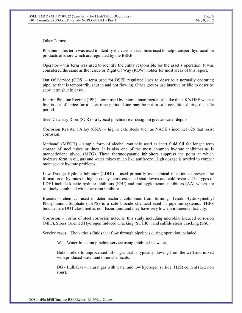
Other Terms:
Pipeline – this term was used to identify the various steel lines used to help transport hydrocarbon products offshore which are regulated by the BSEE.
Operator – this term was used to identify the entity responsible for the asset’s operation. It was considered the same as the lessee or Right Of Way (ROW) holder for most areas of this report.
Out Of Service (OOS) – term used for BSEE regulated lines to describe a normally operating pipeline that is temporarily shut in and not flowing. Other groups use inactive or idle to describe short term shut in cases.
Interim Pipeline Regime (IPR) – term used by international regulator’s like the UK’s HSE when a line is out of serice for a short time period. Line may be put in safe condition during that idle period.
Steel Catenary Riser (SCR) – a typical pipeline riser design in greater water depths.
Corrosion Resistent Alloy (CRA) – high nickle steels such as NACE’s inconnel 625 that resist corrosion.
Methanol (MEOH) – simple form of alcohal routinely used as inert fluid fill for longer term storage of steel tubes or lines. It is also one of the most common hydrate inhibitors as is monoethylene glycol (MEG). These thermodynamic inhibitors suppress the point at which hydrates form in oil, gas and water mixes much like antifreeze. High dosage is needed to combat more severe hydrate problems.
Low Dosage Hydrate Inhibitor (LDHI) – used primarily as chemical injection to prevent the formation of hydrates in higher cut systems, extended shut downs and cold restarts. The types of LDHI include kinetic hydrate inhibitors (KHI) and anti-agglomerant inhibitors (AA) which are routinely combined with corrosion inhibitor.
Biocide – chemical used to deter bacteria cololonies from forming. TetrakisHydroxymethyl Phosphonium Sulphate (THPS) is a safe biocide chemical used in pipeline systems.. THPS biocides are DOT classified as non-hazardous, and they have very low environmental toxicity.
Corrosion – Forms of steel corrosion noted in this study including microbial induced corrosion (MIC), Stress Oriented Hydrogen Induced Cracking (SOHIC), and sulfide stress cracking (SSC).
Service cases – The various fluids that flow through pipelines during operation included:
WI – Water Injection pipeline service using inhibited seawater.
Bulk - refers to unprocessed oil or gas that is typically flowing from the well and mixed with produced water and other chemicals.
BG - Bulk Gas – natural gas with water and low hydrogen sulfide (H2S) content (i.e.: non sour).

BSEE TA&R - M11PC00022 (Timeframe for Flush/Fill of OOS Lines) Page 6 F101 Consulting (USA), LP. - Study No PLGS02.R1 – Rev.1 May 9, 2012
G/C- Gas/Condensate service where non sour bulk gas includes significant liquefied heavy ends like butane and water.
BO- Bulk Oil service which includes non sour oil with produced water.
Sour service - includes highly H2S containing natural gas and oil product mixes.
Sweet service - includes low H2S containing natural gas and oil product mixes. Typically export grade oil and gas is low in H2S and CO2.
3. REGULATORY ORGANIZATION OF THE OUTER CONTINENTAL SHELF
The Minerals Management Service (MMS) was renamed the Bureau of Ocean Energy Management, Regulation and Enforcement (BOEMRE) in mid 2010. On October 1, 2010, the revenue collection arm of the former MMS became the Office of Natural Resources Revenue. On January 19, 2011, the resource development and energy management functions of BOEMRE and the safety and enforcement functions of BOEMRE were separated. The new Bureau of Ocean Energy Management (BOEM) is responsible for managing development of the nation’s offshore resources in an environmentally and economically responsible way. Functions include Leasing, Plan Administration, Environmental Studies, National Environmental Policy Act (NEPA) Analysis, Resource Evaluation, Economic Analysis and the Renewable Energy Program. The new Bureau of Safety and Environmental Enforcement (BSEE) enforces safety and environmental regulations. Functions include field operations including Permitting and Research, Inspections, Offshore Regulatory Programs, Oil Spill Response, and newly formed Training and Environmental Compliance functions. The BOEM and BSEE Regional Offices conduct all leasing, permitting and resource management functions on the Outer Continental Shelf (OCS). The OCS consists of submerged Federal lands off the United States coasts. The BOEM leases these Federal offshore areas for exploration and production and the BSEE closely monitors OCS operations to maintain high safety levels and protect coastal environments. The BOEM/BSEE meets major energy needs through management of the production. This oversight and management provides about $6 billion in annual revenue benefits to the Nation. The OCS provides around 30% of the nation's domestic oil production and nearly 10% of domestic natural gas production as of 2010. During the last few years, the growing USA onshore gas production has been limiting the overall percentage offshore gas production contributes to the gross domestic production. Based on the DOI/DOT Memorandum of Understanding from 1996, DOI, as an agent to DOT, is authorized by DOT to perform certain OCS inspection tasks for pipelines under DOT responsibility. The three BSEE regional offices are located in New Orleans, La. (GOM Region), Camarillo, Calif. (Pacific Region), and Anchorage, Alaska (Alaska Region).
OOSlineFlushFillTimeline-BSEEReport-R1-9May12.docx
Gulf Of Mexico Region (GOMR):

BSEE TA&R - M11PC00022 (Timeframe for Flush/Fill of OOS Lines) Page 7 F101 Consulting (USA), LP. - Study No PLGS02.R1 – Rev.1 May 9, 2012
The GOMR’s three planning areas include 43 million acres under lease and currently oversees operational and production activity from ~3,500 oil and gas platforms located offshore GOM and 33,000 miles of pipeline. In 2011, the region provided 422.3 MMbbls oil and 1,637.6 BCF gas.
Figure 1: GOMR Area Map
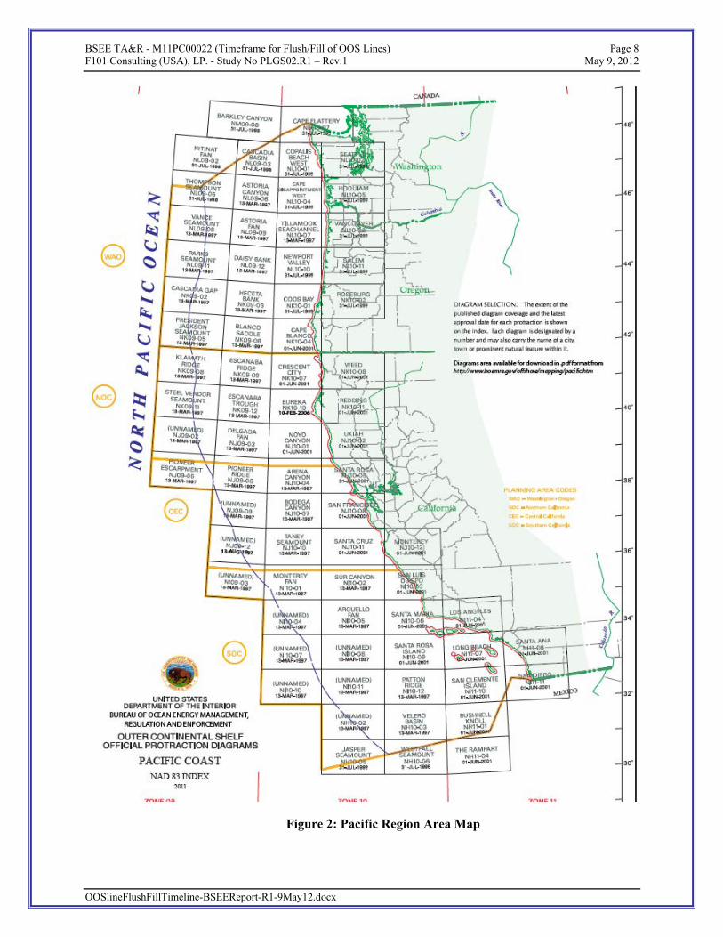
Pacific Region:
The Pacific Region currently oversees operational and production activity from 23 oil and gas platforms located offshore southern California. These facilities typically account for about 24 million barrels of oil and 47 billion cubic feet of gas annually. In 2011, the region provided 17.98 MMbbls oil and 33.56 BCF gas.
OOSlineFlushFillTimeline-BSEEReport-R1-9May12.docx
BSEE TA&R - M11PC00022 (Timeframe for Flush/Fill of OOS Lines) Page 8 F101 Consulting (USA), LP. - Study No PLGS02.R1 – Rev.1 May 9, 2012
Figure 2: Pacific Region Area Map
OOSlineFlushFillTimeline-BSEEReport-R1-9May12.docx

BSEE TA&R - M11PC00022 (Timeframe for Flush/Fill of OOS Lines) Page 9 F101 Consulting (USA), LP. - Study No PLGS02.R1 – Rev.1 May 9, 2012
Alaska Region:
The Alaska Region oversees more than one billion acres on the Outer Continental Shelf and more than 6,000 miles of coastline -- more coastline than in the rest of the United States combined. The region encompasses the Arctic ocean, the Bering Sea and the northern Pacific Ocean. In 2011, the region provided 4.45 MMbbls oil and 166.45 BCF gas.
Figure 3: Alaska Region Area Map
4. OUTER CONTINENTAL SHELF PRODUCTION AND DEVELOPMENT
4.1 OCS Regions Impact to Domestic Consumption
All three OCS regions are important to the United States as combined they provided 30% of the oil and 10% of the gas total domestic production in 2010. Domestic production constitutes between 40% and 50% of the hydrocarbons comsumed each year in the USA with the balance being imported oil & gas. Domestic oil & gas production charts are identified in Figure 4.
During the last few years, the growing USA onshore gas production has reduced the overall percentage offshore gas production contributes to the gross domestic production.
OOSlineFlushFillTimeline-BSEEReport-R1-9May12.docx

BSEE TA&R - M11PC00022 (Timeframe for Flush/Fill of OOS Lines) Page 10 F101 Consulting (USA), LP. - Study No PLGS02.R1 – Rev.1 May 9, 2012
Figure 4: Natural Gas and Crude Oil Domestic Production (1966-2008)
OOSlineFlushFillTimeline-BSEEReport-R1-9May12.docx
BSEE TA&R - M11PC00022 (Timeframe for Flush/Fill of OOS Lines) Page 11 F101 Consulting (USA), LP. - Study No PLGS02.R1 – Rev.1 May 9, 2012
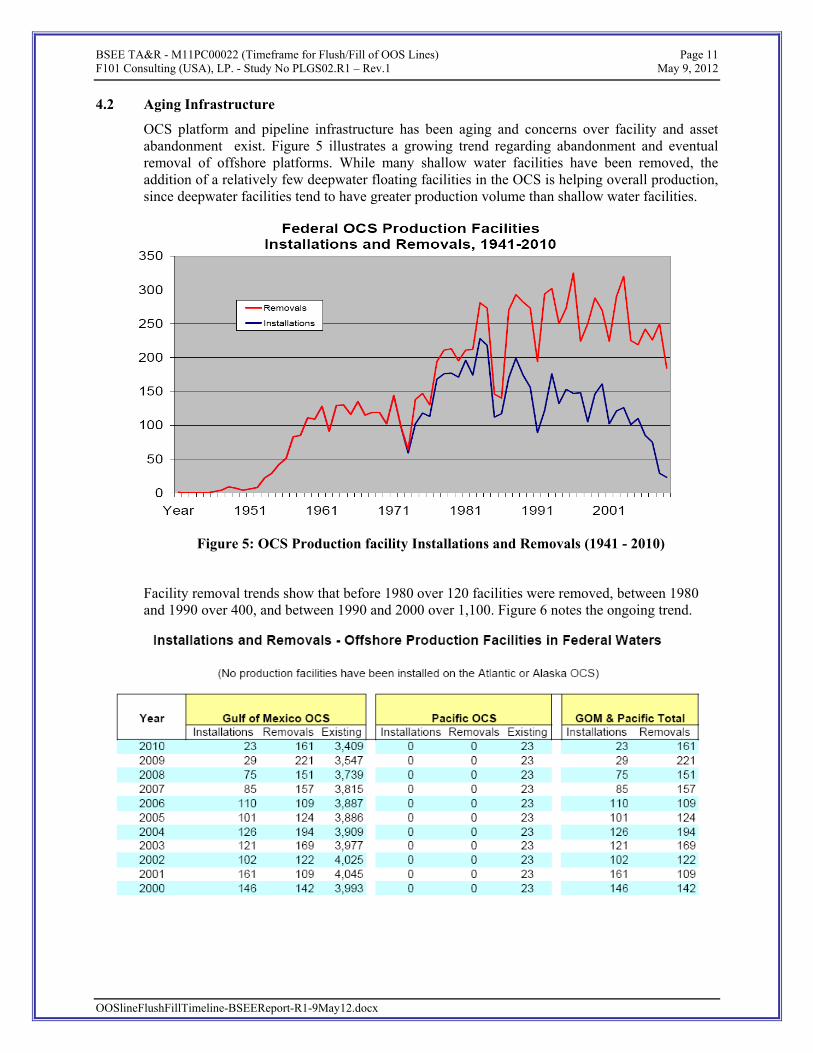
4.2 Aging Infrastructure
OCS platform and pipeline infrastructure has been aging and concerns over facility and asset abandonment exist. Figure 5 illustrates a growing trend regarding abandonment and eventual removal of offshore platforms. While many shallow water facilities have been removed, the addition of a relatively few deepwater floating facilities in the OCS is helping overall production, since deepwater facilities tend to have greater production volume than shallow water facilities.
Figure 5: OCS Production facility Installations and Removals (1941 - 2010)
Facility removal trends show that before 1980 over 120 facilities were removed, between 1980 and 1990 over 400, and between 1990 and 2000 over 1,100. Figure 6 notes the ongoing trend.
OOSlineFlushFillTimeline-BSEEReport-R1-9May12.docx

BSEE TA&R - M11PC00022 (Timeframe for Flush/Fill of OOS Lines) Page 12 F101 Consulting (USA), LP. - Study No PLGS02.R1 – Rev.1 May 9, 2012
Figure 6: OCS Production Facility Installation and Removal List (2000 - 2010)
4.3 Out Of Service Pipeline Trends
In the Gulf of Mexico, owner/ operators are decommissioning structures and pipelines faster than they are installing new facilities. The trend is that owner/operators are moving into fewer, larger deeper water infrastructure while the shallower water reservoirs (the “shelf”) are being depleted. For facilities, the trend has gone from 4,045 structures in 2001 to 3,114 structures at the end of 2011. The pipeline trend is similar with fewer new build lines and more abandonment each year.
YEAR Active
In Service
DoI / (DoT)
Pipelines Installed During Year
Pipelines Abandoned
During Year
OOS Idle DOI/
(DOT)
Timeline Ext
Requ for OOS
line F&F
Notes
2000 5386 (1444)
442 (18)
2001 300 222 2002 272 214 2003 244 462 2004 257 227 2005 205 266 2006 258 219 261 2007 290 458 239 2008 252 339 71 2009 159 422 158 2010 118 483 66 Macondo
incident 2011 3753
(939) 59 357 931
(109)782
(166) 23
OOSlineFlushFillTimeline-BSEEReport-R1-9May12.docx

BSEE TA&R - M11PC00022 (Timeframe for Flush/Fill of OOS Lines) Page 13 F101 Consulting (USA), LP. - Study No PLGS02.R1 – Rev.1 May 9, 2012
Over the years, more and more aging pipelines have been put OOS and later typically abandoned in place. This “aging iron in the field” issue is a growing concern, but not the focus of this study.
The key focus of this study is on pipelines that go OOS but which are likely to come back in service later. The BSEE database shows 931 DOI lines and 109 DOT pipelines in OOS status as of 2011. While the BSEE has active field management and oversight of DOT and DOI lines, this study will focus on OOS pipelines. Support and input from DOT and transmission companies were provided for the study.
Based on feedback from operators and the government, no significant trouble was found regarding with OOS lines. The very few cases of hydro test failures by lines brought back into service after re-hydrotesting were not identified with a root cause of corrosion caused by their OOS time. Therefore, the current 1- year rule and the companies’ current practices have been successful in the USA. However, similar feedback exists from international pipelines regulated by risk-based codes.
Figure 7: GOM OCS Overview of Pipeline Infrastructure
5. OUT OF SERVICE PIPELINE PRACTICES
A normal pipeline’s lifecycle begins with design, fabrication, installation, pre commissioning and commissioning. Once pre commissioning hydrotest and dewatering is complete and the well and associated systems are commissioned and flowing, the pipeline is in operational mode. During operation, there are times when the line segment may be shut in due to other construction work on a tieback platform, due to the segment being designed as a dead leg during normal flow, or due to near proximity installation of another asset, or due to the need for repair or in response to inbound tropical storms. If these “idle” or shut in times extend long enough, then the line is considered out of service (OOS).
Most deepwater water subsea flowlines are not designed for the passage of pipeline pigs, which limits the ability to inspect their integrity. Other than for pre commissioning, repair or future tie in purposes, infield lines tend not to be pigged. Fortunately the intensive use and monitoring of
OOSlineFlushFillTimeline-BSEEReport-R1-9May12.docx
BSEE TA&R - M11PC00022 (Timeframe for Flush/Fill of OOS Lines) Page 14 F101 Consulting (USA), LP. - Study No PLGS02.R1 – Rev.1 May 9, 2012
chemical injection cocktails down hole, at the subsea tree, and in cases at other locations tends to mitigate corrosion and other production risks such as blockages by hydrates or wax plugs.
Export pipelines are designed to be periodically pigged. In some cases, this also leads to occasional “intelligent” pigging by the operator/ lessee for integrity management purposes. These lines are typically relatively low pressure with thinner steel pipe wall thickness which allow for the more effective use of such inspection tools.
OOSlineFlushFillTimeline-BSEEReport-R1-9May12.docx
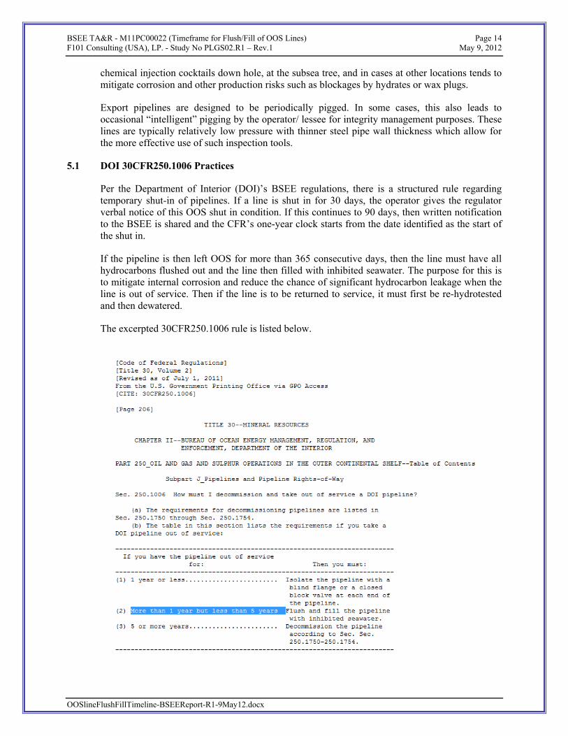
5.1 DOI 30CFR250.1006 Practices
Per the Department of Interior (DOI)’s BSEE regulations, there is a structured rule regarding temporary shut-in of pipelines. If a line is shut in for 30 days, the operator gives the regulator verbal notice of this OOS shut in condition. If this continues to 90 days, then written notification to the BSEE is shared and the CFR’s one-year clock starts from the date identified as the start of the shut in.
If the pipeline is then left OOS for more than 365 consecutive days, then the line must have all hydrocarbons flushed out and the line then filled with inhibited seawater. The purpose for this is to mitigate internal corrosion and reduce the chance of significant hydrocarbon leakage when the line is out of service. Then if the line is to be returned to service, it must first be re-hydrotested and then dewatered.
The excerpted 30CFR250.1006 rule is listed below.

BSEE TA&R - M11PC00022 (Timeframe for Flush/Fill of OOS Lines) Page 15 F101 Consulting (USA), LP. - Study No PLGS02.R1 – Rev.1 May 9, 2012
Since this is a time-based rule, the ability for an operator to restart the line for a short time before 365 days elapses in OOS condition exists for lines that are not plugged or otherwise incapable of flowing product. Even a short period of operation serves to circulate the product and refresh the chemical injection cocktail mix within the product along the line’s inner pipe wall.
5.2 DOT 49CFR192.727 and 49CFR195.59 Practices
Per the Department of Transportation (DOT)‘s US Department of Transportation Pipeline and Hazardous Materials Safety Administration (PHMSA) regulations, there is no hard and fast rule for temporary out-of-service export lines.
Most export lines are rarely shut down and when they are, it tends to be for permanent abandonment. For DOT export lines, the typical exception to its being in service is when under repair or having a cold tap construction tie in. Further, these export lines tend to be of piggable design, operate under lower pressures and have thinner steel wall thickness than DOI pipeline. This is in contrast to the DOI’s infield pipelines that more routinely go in and out of service. DOI subsea lines tend to be in higher pressure and temperature service, thicker wall and see more change due to declining fields and on the addition of new wells. Looped subsea pipeline systems commonly have long-term dead leg segments.
PHMSA tends to use the term “inactive” or idle for short-term OOS lines. The rules listed below discuss permanent and not temporary line abandonment practice.
OOSlineFlushFillTimeline-BSEEReport-R1-9May12.docx

BSEE TA&R - M11PC00022 (Timeframe for Flush/Fill of OOS Lines) Page 16 F101 Consulting (USA), LP. - Study No PLGS02.R1 – Rev.1 May 9, 2012
192.727 Abandonment or deactivation of facilities. (Gas)
(b) Each pipeline abandoned in place must be disconnected from all sources and supplies of gas; purged of gas; in the case of offshore pipelines, filled with water or inert materials; and sealed at the ends. However, the pipeline need not be purged when the volume of gas is so small that there is no potential hazard.
(c ) Except for service lines, each inactive pipeline that is not being maintained under this part must be disconnected from all sources and supplies of gas; purged of gas; in the case of offshore pipelines, filled with water or inert materials; and sealed at the ends. However, the pipeline need not be purged when the volume of gas is so small that there is no potential hazard.
(g) For each abandoned offshore pipeline facility or each abandoned onshore pipeline facility that crosses over, under or through a commercially navigable waterway, the last operator of that facility must file a report upon abandonment of that facility.
195.59 Abandonment or deactivation of facilities. (Oil)
For each abandoned offshore pipeline facility or each abandoned onshore pipeline facility that crosses over, under or through a commercially navigable waterway, the last operator of that facility must file a report upon abandonment of that facility.
One variation with DOT export lines is the administrative risk of an owner/ operator (ie: ROW holder) losing its Right Of Way (ROW) if proper “inactive” notice is not given. The OOS or Temporary Cessation for ROW’s is very much a DOI regulation. Even though the export pipelines are regulated, in most instances by DOT, they are permitted with DOI as ROWs. Owner /operators surveyed during the study indicated they were at risk of losing ROW if their notice was not given within 90 days which created an administrative burden to re-establish. Additionally, if the pipeline has been in an approved Cessation of Operation mode for over a year, a hydro-test is required before returning to an active status.
OOSlineFlushFillTimeline-BSEEReport-R1-9May12.docx
5.3 International Regulator Practices
International regulatory bodies such as the United Kingdom’s (UK) Health & Safety Executive (HSE) and the Department of Energy & Climate Change (DECC) support a relatively non-prescriptive approach to temporary abandonment of pipelines.
This same philosophical approach applies to Australian regulators of the National Offshore Petroleum Safety and Environmental Management Authority (NOPSEMA) and their preference for operators to use DNV-OS-F101 for guidance. The typical guidance codes international regulators support and follow are ISO and DNV standards. Relevant to this study topic is DNV OS- F101, Section 11’s requalification of pipelines and ISO/TS 12747’s pipeline life extension guidance.
Overseas cases illustrate the regulators approving operators to use dead oil and circulate it in an oil pipeline when that line is to go out of service for a relatively short period. In cases, gas lines

BSEE TA&R - M11PC00022 (Timeframe for Flush/Fill of OOS Lines) Page 17 F101 Consulting (USA), LP. - Study No PLGS02.R1 – Rev.1 May 9, 2012
OOSlineFlushFillTimeline-BSEEReport-R1-9May12.docx
that have dry gas may be left as is, again for a short time, if it can be demonstrated that doing so will not increase corrosion failure risk. Depending on the product and testing results, a precursor of biocide is typically added as a prophylactic versus corrosion when deemed appropriate for the given service and integrity management situation. It was also noted that new build pipelines overseas are expected to be designed piggable by operators.
5.3.1 Department of Energy & Climate Change (DECC)
Notification of Disused Pipelines
During the course of a field's life, pipelines or parts of pipelines may be taken out of use, e.g. due to corrosion, problems with reservoir pressure, damage to the pipeline, etc. When this happens, under the Petroleum Act 1998 the Secretary of State1 has the option of immediately calling for a full decommissioning programme. This is not always considered an appropriate option however, and so it has been agreed consideration will be given to handling suitable pipelines, under an informal decommissioning regime, thereby deferring a formal programme until the end of the field's life.
The Interim Pipeline Regime is intended to ensure out-of-use lines do not pose a risk to other users of the sea or the environment and that they are covered by an appropriate surveying and maintenance regime from the point when they are taken out of use until approval of the formal decommissioning programme, which is usually at the end of field life. It should be noted that any interim solution should not prejudice the final decommissioning options for that line, including complete removal.
The Department expects operators to submit details of out-of-use pipelines / parts of a pipeline as soon as they are taken out of use. Please email [email protected] or complete the Disused pipeline notification form.
If you are an operator aware of any out-of-use pipelines that have not been referred to the Department, please also notify DECC through the same channels.
If a formal decommissioning programme is not immediately deemed suitable, details of the out-of-use pipeline(s) will be circulated to other government departments for comment. Following this, DECC will decide one of the following:
• we are content with the proposals for monitoring and maintaining the out-of-use pipeline • we request additional information or further remedial action • we request a formal decommissioning programme
Following confirmation a pipeline has been accepted under the Interim Pipeline Regime, the Offshore Decommissioning Unit will continue to monitor the condition of the pipeline by asking the operator to confirm the status of the pipeline remains unchanged following future surveys.
1 To avoid any confusion it is noted that the term “Secretary of State” in the UK refers to “a member of Parliament who is in charge of a government department”

BSEE TA&R - M11PC00022 (Timeframe for Flush/Fill of OOS Lines) Page 18 F101 Consulting (USA), LP. - Study No PLGS02.R1 – Rev.1 May 9, 2012
5.3.2 Health & Safety Executive (HSE) – Pipeline Safety Regulations
(General) Arrangement for Incidents and Emergencies
12. The operator shall ensure that no fluid is conveyed in a pipeline unless adequate arrangements have been made for dealing with—
(a)an accidental loss of fluid from;
(b)discovery of a defect in or damage to; or
(c)other emergency affecting the pipeline.
(General) Decommissioning
14. (1) The operator shall ensure that a pipeline which has ceased to be used for the conveyance of any fluid is left in a safe condition.
(2) The operator of a pipeline shall ensure that work done in discharge of the duty contained in paragraph (1) is performed safely.
(Major Accident Hazard Pipelines) Notification before use
21. The operator shall ensure that no fluid is conveyed in a major accident hazard pipeline, or conveyed following a period in which it has been out of commission (other than for routine maintenance), until the expiration of 14 days, or of such shorter period as the Executive may in that case approve, from the receipt by it of a notification of the date on which it is intended to convey or, as the case may be, resume the conveyance of fluid in the pipeline.
5.3.3 “Example” Requirements in Platform Operations Procedures Manual
Below is an edited excerpt from an approved operations manual for a large pipeline system. The Corrosion Control Strategy noted is fairly typical overseas for similar systems. HSE provided oversight in this example for the supporting Safety Case. Displacing the line to export crude In agreement with current operating procedures, the flowlines will be displaced to Xxxxxx export crude in case these flowlines are not flowing for more than 24 hours. The same holds for sections of flowlines. This is to prevent corrosion and wax formation in case the lines are not in continuous service. In case of shutdown of GE-03, it is important to realise that a 7km section of the Xxxxxx F flowline between the GF-01 tie-in point and the Xxxxxx E towhead (between the Pig P Valve XEV-10114 and valve XEV-1113) will be left stagnant. Xxxxxx export crude can be pumped from the platform either via the E flowline or via the F flowline. Both options are feasible and the pump direction should be selected to minimize deferment. It is expected that pumping via the F-line normally will be the quickest method resulting in the least deferment. Note that during displacement of the flowlines or sections of the flowlines to export crude both ESP's should not be operated to prevent potential detrimental surge and backpressure effects on the ESP's.
OOSlineFlushFillTimeline-BSEEReport-R1-9May12.docx
Xxxxxx C Pipeline Corrosion Control Strategy for Closed-in Pipelines
BSEE TA&R - M11PC00022 (Timeframe for Flush/Fill of OOS Lines) Page 19 F101 Consulting (USA), LP. - Study No PLGS02.R1 – Rev.1 May 9, 2012
Strategy for closed-in flowlines, including dead legs: The Xxxxxx C field has 8 wells with 12 flowlines. Four wells have dual flowlines and four have single flowlines. For practical purposes, the platform should use the following fluids (in order of preference) in case a flowline needs to be closed in:
(1) Crude oil of export quality ('dead crude'; low CO2 content) (2) Production fluids containing corrosion inhibitor (30ppm based on PW) (3) Methanol and/or glycol (non-corrosive but probably too expensive) (4) Untreated seawater (not longer than 1 month).
Justification: From a material balance point of view, corrosion will stop once all CO2 in the production fluids is gone. Once a line has been filled with production fluids, it is better to leave it alone as long as possible because flowing the line will replenish the corrosive ingredients. Bacteria cannot accumulate inside Xxxxxx C production fluids that have come straight from the reservoir. Seawater works differently. Initially, oxygen corrosion will occur, which is a more aggressive pitting agent than CO2. Once all oxygen is gone, anaerobic bacteria (SRBs) may develop. Seawater should therefore be treated with biocide if being left in the pipeline for a month or more. Because only untreated seawater can introduce bacteria, this method is classed as 'bad practice'. Prior to introducing seawater in the flow lines the onshore corrosion engineer should be contacted.
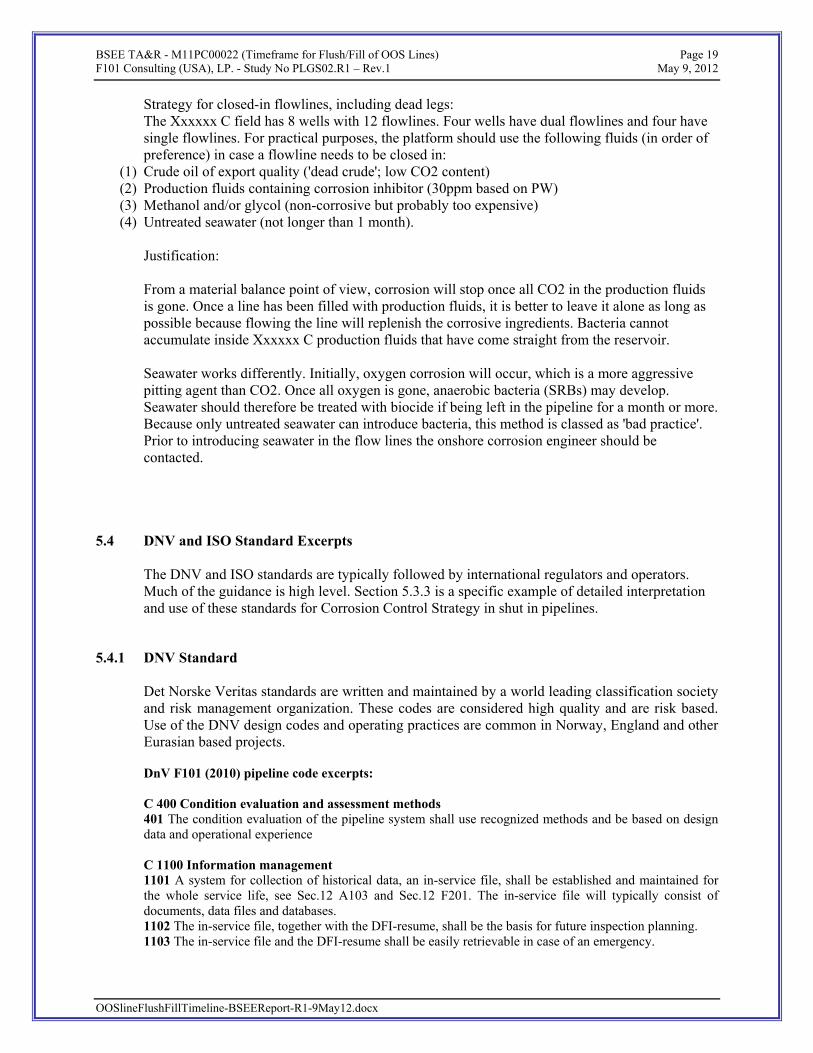
5.4 DNV and ISO Standard Excerpts The DNV and ISO standards are typically followed by international regulators and operators. Much of the guidance is high level. Section 5.3.3 is a specific example of detailed interpretation and use of these standards for Corrosion Control Strategy in shut in pipelines.
OOSlineFlushFillTimeline-BSEEReport-R1-9May12.docx
5.4.1 DNV Standard Det Norske Veritas standards are written and maintained by a world leading classification society and risk management organization. These codes are considered high quality and are risk based. Use of the DNV design codes and operating practices are common in Norway, England and other Eurasian based projects. DnV F101 (2010) pipeline code excerpts: C 400 Condition evaluation and assessment methods 401 The condition evaluation of the pipeline system shall use recognized methods and be based on design data and operational experience C 1100 Information management 1101 A system for collection of historical data, an in-service file, shall be established and maintained for the whole service life, see Sec.12 A103 and Sec.12 F201. The in-service file will typically consist of documents, data files and databases. 1102 The in-service file, together with the DFI-resume, shall be the basis for future inspection planning. 1103 The in-service file and the DFI-resume shall be easily retrievable in case of an emergency.
BSEE TA&R - M11PC00022 (Timeframe for Flush/Fill of OOS Lines) Page 20 F101 Consulting (USA), LP. - Study No PLGS02.R1 – Rev.1 May 9, 2012
OOSlineFlushFillTimeline-BSEEReport-R1-9May12.docx
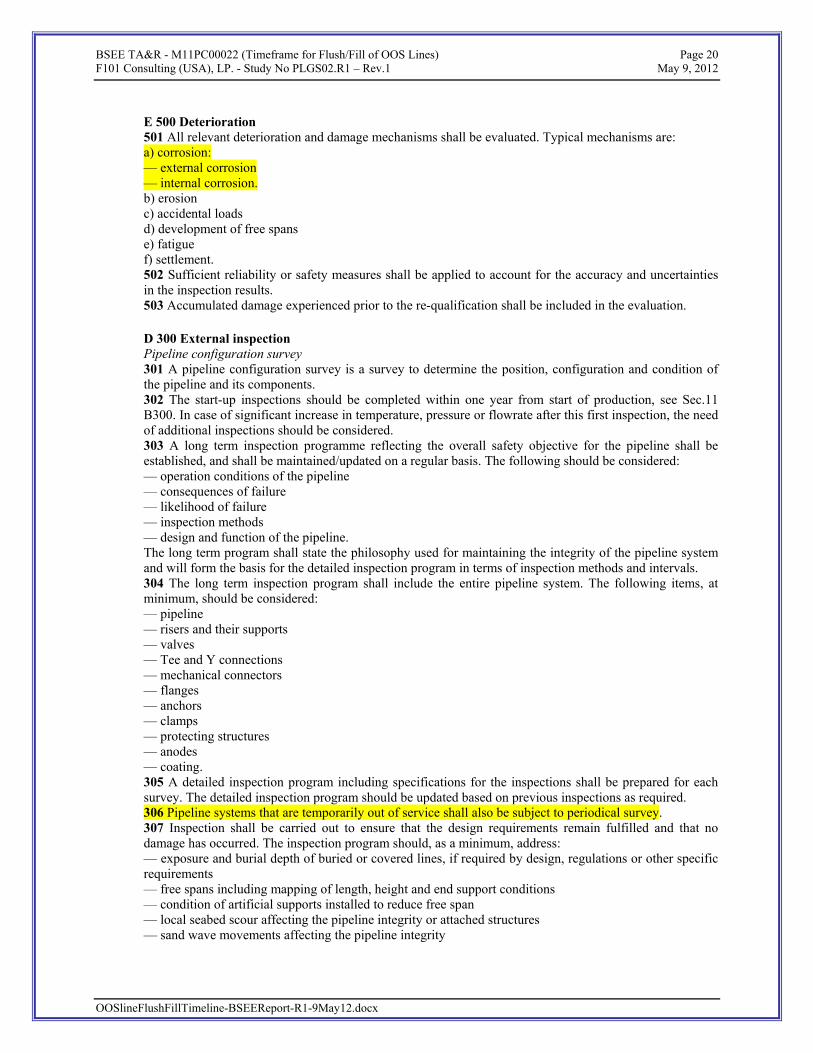
E 500 Deterioration 501 All relevant deterioration and damage mechanisms shall be evaluated. Typical mechanisms are: a) corrosion: — external corrosion — internal corrosion. b) erosion c) accidental loads d) development of free spans e) fatigue f) settlement. 502 Sufficient reliability or safety measures shall be applied to account for the accuracy and uncertainties in the inspection results. 503 Accumulated damage experienced prior to the re-qualification shall be included in the evaluation. D 300 External inspection Pipeline configuration survey 301 A pipeline configuration survey is a survey to determine the position, configuration and condition of the pipeline and its components. 302 The start-up inspections should be completed within one year from start of production, see Sec.11 B300. In case of significant increase in temperature, pressure or flowrate after this first inspection, the need of additional inspections should be considered. 303 A long term inspection programme reflecting the overall safety objective for the pipeline shall be established, and shall be maintained/updated on a regular basis. The following should be considered: — operation conditions of the pipeline — consequences of failure — likelihood of failure — inspection methods — design and function of the pipeline. The long term program shall state the philosophy used for maintaining the integrity of the pipeline system and will form the basis for the detailed inspection program in terms of inspection methods and intervals. 304 The long term inspection program shall include the entire pipeline system. The following items, at minimum, should be considered: — pipeline — risers and their supports — valves — Tee and Y connections — mechanical connectors — flanges — anchors — clamps — protecting structures — anodes — coating. 305 A detailed inspection program including specifications for the inspections shall be prepared for each survey. The detailed inspection program should be updated based on previous inspections as required. 306 Pipeline systems that are temporarily out of service shall also be subject to periodical survey. 307 Inspection shall be carried out to ensure that the design requirements remain fulfilled and that no damage has occurred. The inspection program should, as a minimum, address: — exposure and burial depth of buried or covered lines, if required by design, regulations or other specific requirements — free spans including mapping of length, height and end support conditions — condition of artificial supports installed to reduce free span — local seabed scour affecting the pipeline integrity or attached structures — sand wave movements affecting the pipeline integrity

BSEE TA&R - M11PC00022 (Timeframe for Flush/Fill of OOS Lines) Page 21 F101 Consulting (USA), LP. - Study No PLGS02.R1 – Rev.1 May 9, 2012
— excessive pipe movements including expansion effects — identification of areas where upheaval buckling or excessive lateral buckling has taken place — integrity of mechanical connections and flanges — integrity of sub-sea valves including protective structure — Y- and Tee connections including protective structure — pipeline settlement in case of exposed pipeline, particularly at the valve/Tee locations — the integrity of pipeline protection covers (e.g. mattresses, covers, sand bags, gravel slopes, etc.) — mechanical damage to pipe, coatings and anodes — major debris on, or close to, the pipeline that may cause damage to the pipeline or the external corrosion protection system — leakage. 308 The risers shall be part of the long-term inspection programme for the pipeline system. Integrity shall be ensured through all phases, from initial concept through to final de-commissioning, see Figure 1. This standard defines two integrity stages: establish integrity in the concept development, design and construction phases; and maintain integrity in the operations phase.
Section 11: A 100 Objective 101 The purpose of this section is to provide minimum requirements for the safe and reliable operation of submarine pipeline systems (see Sec.11 A500) for the whole service life with main focus on pipeline integrity management (PIM). A 200 Scope and application 201 This section covers the submarine pipeline system phases operations and abandonment. Operations consist of commissioning, operation and de-commissioning. 202 Pipeline integrity is the ability of the submarine pipeline system to operate safely and withstand the loads imposed during the pipeline lifecycle. 203 The pipeline integrity management process is the combined process of threat identification, risk assessments, planning, monitoring, inspection, maintenance etc. to maintain pipeline integrity. 204 The equipment scope limits include pipeline and components according to the definition of a submarine pipeline system in Sec.1 C335. The PIM principles and methodology are applicable to pipeline systems in general. A 300 Responsibilities 301 Pipeline integrity management is the responsibility of the operator. The operator needs to ensure that the integrity of the pipeline is not compromised.
OOSlineFlushFillTimeline-BSEEReport-R1-9May12.docx

BSEE TA&R - M11PC00022 (Timeframe for Flush/Fill of OOS Lines) Page 22 F101 Consulting (USA), LP. - Study No PLGS02.R1 – Rev.1 May 9, 2012
302 At all times during the operational life of the pipeline system, responsibilities must be clearly defined and allocated. B 300 Operational verification 301 After stable production has been reached it shall be verified that the operational limits are within design conditions. Important issues can be: — flow parameters (pressure, temperature, etc.) — CP-system — expansion — movement — lateral snaking — free span and exposure 302 Scheduling of the first inspection of the wall thickness shall be evaluated based on the corrosivity of the fluid, expected operational parameters, robustness of the internal corrosion protection system (inhibitor system), the corrosion allowance used in the design, the effectiveness of the QA/QC system applied during fabrication and construction, and the defect sizing capabilities of the inspection tool that will be used during operation of the pipeline. C. Integrity Management System C 100 General 101 The operator shall establish and maintain an integrity management system which as a minimum includes the following elements: — company policy — organisation and personnel — condition evaluation and assessment methods — planning and execution of activities — management of change — operational controls and procedures — contingency plans — reporting and communication — audit and review — information management. The activity plans are the result of the integrity management process by use of recognised assessment methods, see Sec.11 D. D. Integrity Management Process D 100 General 101 The integrity management process consists of the following steps: a) Evaluation of threats and the condition of the pipeline system. b) Plan and conduct activities including inspection and monitoring. c) Integrity assessment based on inspection and monitoring results and other relevant information. d) Assess need for, and conduct if needed, intervention and repair activities and other mitigating actions. This process shall be performed periodically within regular intervals. 102 The requirements for corrosion inspection and monitoring, and the capability of optional techniques, shall be evaluated at an early stage of pipeline system design. Guidance note: Pipelines and risers manufactured from Corrosion Resistant Alloys (CRA) do not normally require inspection and monitoring of internal corrosion. This must be evaluated in each particular case. ---e-n-d---of---G-u-i-d-a-n-c-e---n-o-t-e--- 103 An inspection and monitoring philosophy shall be established, and shall form the basis for the detailed inspection and monitoring program. The philosophy shall be evaluated every 5 to 10 years. 104 All inspection and monitoring requirements identified during the design phase as affecting safety and reliability during operation shall be covered in the inspection and monitoring program, see Sec.3 B200 and Sec.5 B300.
OOSlineFlushFillTimeline-BSEEReport-R1-9May12.docx
105 A special investigation shall be performed in case of any event which impairs the safety, reliability, strength or stability of the pipeline system. This investigation may initiate further inspections.
BSEE TA&R - M11PC00022 (Timeframe for Flush/Fill of OOS Lines) Page 23 F101 Consulting (USA), LP. - Study No PLGS02.R1 – Rev.1 May 9, 2012
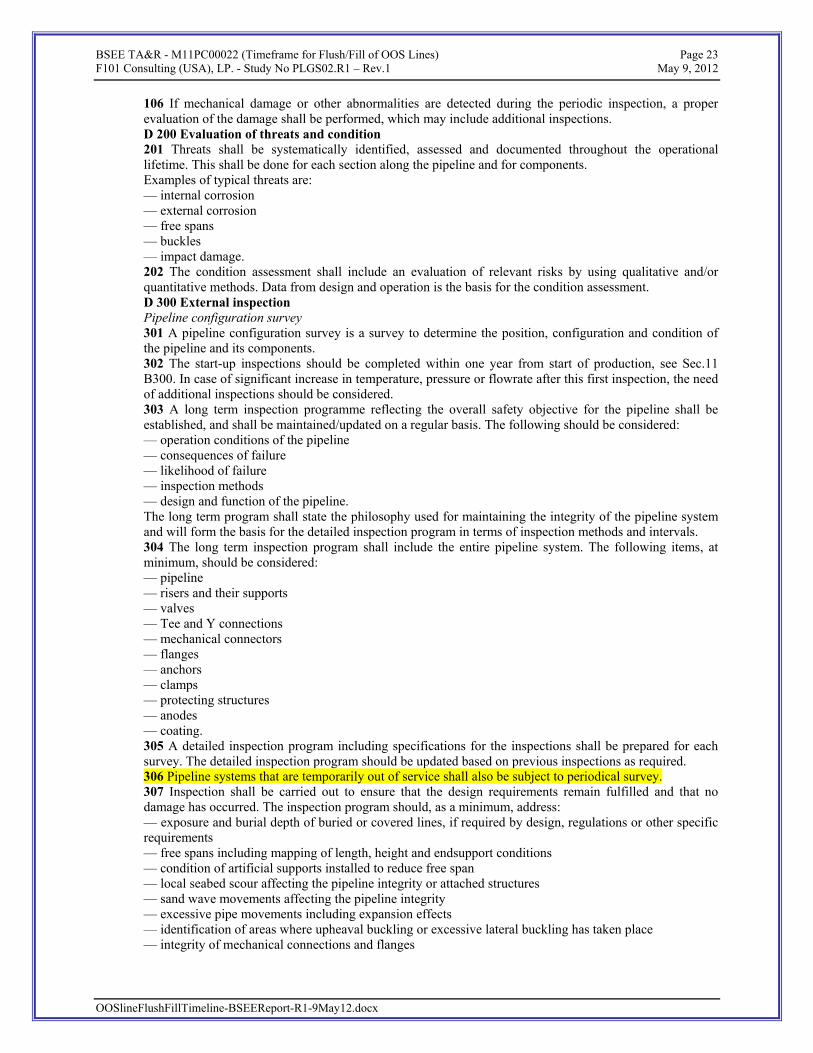
106 If mechanical damage or other abnormalities are detected during the periodic inspection, a proper evaluation of the damage shall be performed, which may include additional inspections. D 200 Evaluation of threats and condition 201 Threats shall be systematically identified, assessed and documented throughout the operational lifetime. This shall be done for each section along the pipeline and for components. Examples of typical threats are: — internal corrosion — external corrosion — free spans — buckles — impact damage. 202 The condition assessment shall include an evaluation of relevant risks by using qualitative and/or quantitative methods. Data from design and operation is the basis for the condition assessment. D 300 External inspection Pipeline configuration survey 301 A pipeline configuration survey is a survey to determine the position, configuration and condition of the pipeline and its components. 302 The start-up inspections should be completed within one year from start of production, see Sec.11 B300. In case of significant increase in temperature, pressure or flowrate after this first inspection, the need of additional inspections should be considered. 303 A long term inspection programme reflecting the overall safety objective for the pipeline shall be established, and shall be maintained/updated on a regular basis. The following should be considered: — operation conditions of the pipeline — consequences of failure — likelihood of failure — inspection methods — design and function of the pipeline. The long term program shall state the philosophy used for maintaining the integrity of the pipeline system and will form the basis for the detailed inspection program in terms of inspection methods and intervals. 304 The long term inspection program shall include the entire pipeline system. The following items, at minimum, should be considered: — pipeline — risers and their supports — valves — Tee and Y connections — mechanical connectors — flanges — anchors — clamps — protecting structures — anodes — coating. 305 A detailed inspection program including specifications for the inspections shall be prepared for each survey. The detailed inspection program should be updated based on previous inspections as required. 306 Pipeline systems that are temporarily out of service shall also be subject to periodical survey. 307 Inspection shall be carried out to ensure that the design requirements remain fulfilled and that no damage has occurred. The inspection program should, as a minimum, address: — exposure and burial depth of buried or covered lines, if required by design, regulations or other specific requirements — free spans including mapping of length, height and endsupport conditions — condition of artificial supports installed to reduce free span — local seabed scour affecting the pipeline integrity or attached structures — sand wave movements affecting the pipeline integrity — excessive pipe movements including expansion effects — identification of areas where upheaval buckling or excessive lateral buckling has taken place
OOSlineFlushFillTimeline-BSEEReport-R1-9May12.docx
— integrity of mechanical connections and flanges

BSEE TA&R - M11PC00022 (Timeframe for Flush/Fill of OOS Lines) Page 24 F101 Consulting (USA), LP. - Study No PLGS02.R1 – Rev.1 May 9, 2012
— integrity of sub-sea valves including protective structure — Y- and Tee connections including protective structure — pipeline settlement in case of exposed pipeline, particularly at the valve/Tee locations — the integrity of pipeline protection covers (e.g. mattresses, covers, sand bags, gravel slopes, etc.) — mechanical damage to pipe, coatings and anodes — major debris on, or close to, the pipeline that may cause damage to the pipeline or the external corrosion protection system — leakage. 308 The risers shall be part of the long-term inspection programme for the pipeline system. In addition to the generally applicable requirements for pipeline inspection, special atten
OOSlineFlushFillTimeline-BSEEReport-R1-9May12.docx
5.4.2 ISO Standards
International Organization for Standardization (ISO) has developed over 19,000 standards on a variety of subjects. ISO Technical Specification 12747 is the recommended practice for pipeline life extensions and was issued in 2011. Its approach and flowchart based methodology have synergy with the “effect” of pipeline life that going OOS may cause to a line.
5 Life extension overview 5.1 General The design life of a pipeline is derived to prevent failure during operation due to time-dependent degradation mechanisms such as corrosion and fatigue. However, the expiry of the design life does not automatically mean that the pipeline system is not fit-for-purpose because ↓ corrosion rates determined during the design process could have been conservative and/or corrosion defects could have been repaired; ↓ the anticipated operational fatigue damage could have been overestimated. Extended operation beyond the pipeline design life can be desirable when recoverable oil and gas remain, or where additional operational assets are tied (or will be tied) into the pipeline system. NOTE There are alternatives to pipeline life extension, such as installing a replacement pipeline. Therefore, a business case is required to determine the most suitable option by comparing the cost of the mitigation necessary to achieve the desired life extension with the cost of a new pipeline. 5.2 Assessment process If the intention is to operate a pipeline system beyond its specified design life, a life extension assessment shall be performed. The aim of this assessment is to demonstrate that by extending the life of the pipeline system, the operator is not exposing society to unacceptable risk. Figure 2 illustrates the pipeline system life extension assessment process. The shaded boxes highlight the distinct stages of the assessment and cross-references to the clause of this Technical Specification dealing with a particular stage are provided. The process begins with a requirement for pipeline extension (item 1) and an assessment of the current integrity of the pipeline system (item 2). The life extension needs should then be defined (item 3), prior to commencement of the life extension assessment (item 4). The life extension assessment shall consider conditions found during the normal operational life that were not considered in the design. Examples are time-dependent cracking mechanisms (e.g. SCC) and manufacturing flaws that can grow under the effect of cyclic loading. The requirements of the life extension assessment are discussed in more detail in 5.3.

BSEE TA&R - M11PC00022 (Timeframe for Flush/Fill of OOS Lines) Page 25 F101 Consulting (USA), LP. - Study No PLGS02.R1 – Rev.1 May 9, 2012
OOSlineFlushFillTimeline-BSEEReport-R1-9May12.docx
Once an acceptable life extension has been determined, the assessment process shall be fully documented (item 5). If life extension is not possible (or if a replacement pipeline is the most economical solution), the pipeline should be decommissioned at the end of the design life as originally planned. 5.3 Assessment requirements The life extension process illustrated in Figure 2 involves an assessment of the current pipeline system integrity and an assessment to determine the suitability of the pipeline system for life extension. The assessment of the current integrity (item 2) shall include, but not be limited to, the following: ↓ review of the pipeline system operational history; ↓ detailed assessment of the current technical integrity of the pipeline system. The life extension assessment (item 4) shall include, but not be limited to, the following: a) risk assessment for extended operation; b) review of the pipeline system design, including a gap analysis to identify the additional requirements of the current design codes; c) assessment of the remnant life of the system, including the following: ↓ corrosion assessment, accounting for both accumulated and future corrosion in combination with a defect assessment; ↓ fatigue assessment, accounting for both accumulated and future fatigue damage; ↓ coating breakdown and CP system degradation assessment; ↓ identification and assessment of any other time-dependent degradation mechanism active in the pipeline;

BSEE TA&R - M11PC00022 (Timeframe for Flush/Fill of OOS Lines) Page 26 F101 Consulting (USA), LP. - Study No PLGS02.R1 – Rev.1 May 9, 2012
d) revision or introduction of the PIMS for the extended operating period, including update of the anomaly limits;
OOSlineFlushFillTimeline-BSEEReport-R1-9May12.docx

BSEE TA&R - M11PC00022 (Timeframe for Flush/Fill of OOS Lines) Page 27 F101 Consulting (USA), LP. - Study No PLGS02.R1 – Rev.1 May 9, 2012
e) identification of any tenure issue (e.g. expiry of permit to occupy land) or statutory requirements (e.g. pipeline license renewal), including a gap analysis to identify any additional regulatory requirements introduced during the pipeline design life; f) review of the adequacy of the safety and operating systems; g) review of the adequacy of the operating and maintenance, emergency response and safety and environmental procedures. Additional studies shall be performed as required, in order to determine the need for remedial measures to mitigate the threats to the pipeline system anticipated during the extended operational period.
OOSlineFlushFillTimeline-BSEEReport-R1-9May12.docx
BSEE TA&R - M11PC00022 (Timeframe for Flush/Fill of OOS Lines) Page 28 F101 Consulting (USA), LP. - Study No PLGS02.R1 – Rev.1 May 9, 2012
6. RISK BASED APPROACH AND ANALYSIS
Study approach used was to identify a “Risk Based” methodology based on line service as an alternate means to determine safe timelines before an Out Of Services (OOS) pipeline is flushed & filled with inhibited seawater. The current prescriptive method is a 1-year clock or timeline for all types of OOS pipelines to be flushed per 30CFR250.1006. Study focus was on failure modes and timeline issues with bringing OOS lines back into service before flushing, filling, and inert fill fluids.
Regulators and industry specialists where interviewed regarding current practice in dealing with out of service pipelines. This includes identification of past line problems, issues and extension of time requests, and getting their suggestion for improved practices.
A workshop was conducted on December 15, 2011 to discuss OOS lines with the input framed by risk-based assessment to outline and review different OOS line service conditions. Focus was on carbon steel pipelines in typical offshore OCS service. Some discussion on CRA lines, flexible, deepwater SCR riser flex and stress joints and sour service was also noted.
A post workshop study team review on the input and suggested action was conducted. The workshop feedback matched up well with the original study plan. Workshop commentary on alternate inert fluids to seawater also matched up well with international best practices.
OOSlineFlushFillTimeline-BSEEReport-R1-9May12.docx
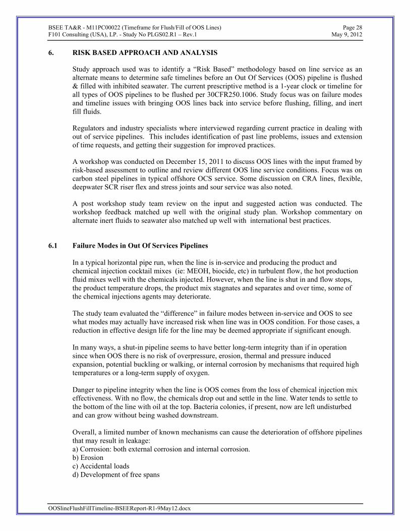
6.1 Failure Modes in Out Of Services Pipelines In a typical horizontal pipe run, when the line is in-service and producing the product and chemical injection cocktail mixes (ie: MEOH, biocide, etc) in turbulent flow, the hot production fluid mixes well with the chemicals injected. However, when the line is shut in and flow stops, the product temperature drops, the product mix stagnates and separates and over time, some of the chemical injections agents may deteriorate. The study team evaluated the “difference” in failure modes between in-service and OOS to see what modes may actually have increased risk when line was in OOS condition. For those cases, a reduction in effective design life for the line may be deemed appropriate if significant enough. In many ways, a shut-in pipeline seems to have better long-term integrity than if in operation since when OOS there is no risk of overpressure, erosion, thermal and pressure induced expansion, potential buckling or walking, or internal corrosion by mechanisms that required high temperatures or a long-term supply of oxygen. Danger to pipeline integrity when the line is OOS comes from the loss of chemical injection mix effectiveness. With no flow, the chemicals drop out and settle in the line. Water tends to settle to the bottom of the line with oil at the top. Bacteria colonies, if present, now are left undisturbed and can grow without being washed downstream.
Overall, a limited number of known mechanisms can cause the deterioration of offshore pipelines that may result in leakage: a) Corrosion: both external corrosion and internal corrosion. b) Erosion c) Accidental loads d) Development of free spans

BSEE TA&R - M11PC00022 (Timeframe for Flush/Fill of OOS Lines) Page 29 F101 Consulting (USA), LP. - Study No PLGS02.R1 – Rev.1 May 9, 2012
e) Fatigue f) Settlement External corrosion can occur on exposed surfaces due to the adverse effect of oxygen and bacteria and is typically mitigated by a combination of a corrosion coating and cathodic protection. Internal corrosion can be caused by CO2 and H2S and organic acids in the produced fluid and by bacteria that were inadvertently introduced during construction, commissioning or operation of a pipeline. H2S can also cause hydrogen induced cracking (HIC), stress oriented HIC and sulfide stress cracking (SSC). Oxygen corrosion can occur in water injection lines and due to the inadvertent introduction of oxygen into otherwise oxygen free fluids. Finally, a pipeline can corrode internally if acid that was used to stimulate a producing or disposal reservoir is left in a pipeline inadvertently. Both external and internal corrosion can be exacerbated by galvanic incompatibility of metallic components and at welds. All of these corrosion phenomena can be controlled by means of material selection, chemical corrosion control, proper design and good installation and commissioning practices. When pipelines are taken out of service, the deterioration mechanisms change to some extent, whereas others remain the same.
a) Corrosion: The external corrosion threats do not change significantly, although the potential corrosion rates may be reduced by a reduction of the temperature. The critical factor is maintaining the cathodic protection as the coating continues to deteriorate over time. The internal corrosion threats can change quite dramatically. - The CO2 corrosion threat is reduced to almost naught, because the lack of flow allows the
development of corrosion products (ie : rust scale) that greatly reduce further corrosion.
- H2S corrosion, which is a threat in systems containing high concentrations of hydrogen
sulfide, is worsened in stagnant conditions. The hydrogen induced cracking (HIC), SOHIC and sulfide stress cracking (SSC) threats were deemed as similar or slightly less
OOSlineFlushFillTimeline-BSEEReport-R1-9May12.docx

BSEE TA&R - M11PC00022 (Timeframe for Flush/Fill of OOS Lines) Page 30 F101 Consulting (USA), LP. - Study No PLGS02.R1 – Rev.1 May 9, 2012
during OOS condition. This risk was further reduced if NACE compliant materials were used and if the line pressure was reduced before shut in.
- Oxygen corrosion will typically be limited since O2 is consumed and then is normally not replenished, so its threat is self-limiting.
- The threat of microbiologically induced corrosion (MIC) increases if nutrients are
available in the fluid, because stagnant conditions are more conducive to proliferation of bacteria in bio-film of inside of line thus creating localized corrosion. Illustration of MIC is shown below in the Corroded Pipe picture.
- The risk of acid corrosion does not change significantly. However, likelihood of trapped acid in a line going OOS is typically very low.
OOSlineFlushFillTimeline-BSEEReport-R1-9May12.docx

BSEE TA&R - M11PC00022 (Timeframe for Flush/Fill of OOS Lines) Page 31 F101 Consulting (USA), LP. - Study No PLGS02.R1 – Rev.1 May 9, 2012
b) The erosion threat reduces to zero when a pipeline is not flowing.
c) The risk of accidental loads does not change significantly.
d) The development of free spans does not change significantly.
e) The fatigue risk does not change significantly, as the greatest risk is due to vortex-induced vibration of the riser, which is independent of whether the line is in operation.
f) The risk of settlement does not change significantly.
A summary of the workshop output on this subject is depicted below.
Figure 8: OOS Induced CS Pipeline Failure Mode “Leak Likelihood” Summary
Based on the failure mode “difference” approach between lines in service and out of service or idle, the only cases of increased to integrity while line is OOS are due to:
• Microbial Induced Corrosion (MIC) • H2S induced corrosion ( highly sour conditions) • Rare condition such as when ongoing acid flow back job is stopped and caustic
fluid is trapped in line during unplanned, emergency shut in. This assumes that base line integrity management protocols in the riser splash zone, cathodic protection anode checks, and periodic survey continue on the line while OOS.
OOSlineFlushFillTimeline-BSEEReport-R1-9May12.docx
BSEE TA&R - M11PC00022 (Timeframe for Flush/Fill of OOS Lines) Page 32 F101 Consulting (USA), LP. - Study No PLGS02.R1 – Rev.1 May 9, 2012
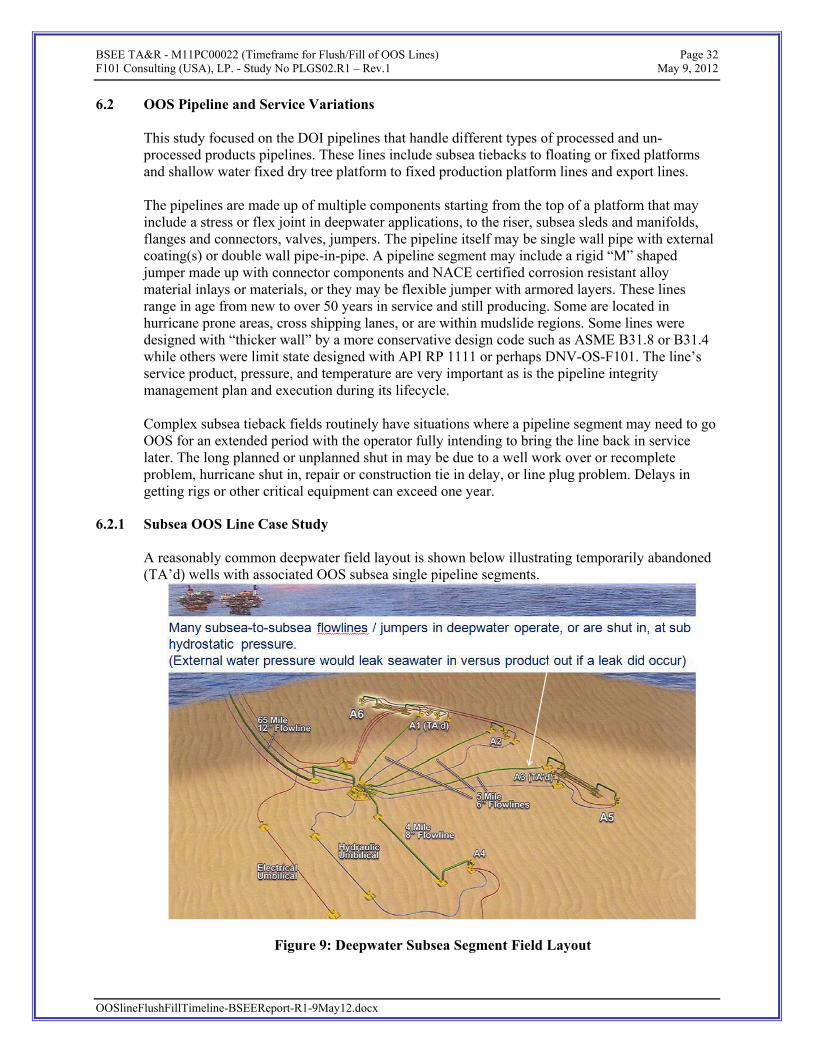
6.2 OOS Pipeline and Service Variations This study focused on the DOI pipelines that handle different types of processed and un-processed products pipelines. These lines include subsea tiebacks to floating or fixed platforms and shallow water fixed dry tree platform to fixed production platform lines and export lines. The pipelines are made up of multiple components starting from the top of a platform that may include a stress or flex joint in deepwater applications, to the riser, subsea sleds and manifolds, flanges and connectors, valves, jumpers. The pipeline itself may be single wall pipe with external coating(s) or double wall pipe-in-pipe. A pipeline segment may include a rigid “M” shaped jumper made up with connector components and NACE certified corrosion resistant alloy material inlays or materials, or they may be flexible jumper with armored layers. These lines range in age from new to over 50 years in service and still producing. Some are located in hurricane prone areas, cross shipping lanes, or are within mudslide regions. Some lines were designed with “thicker wall” by a more conservative design code such as ASME B31.8 or B31.4 while others were limit state designed with API RP 1111 or perhaps DNV-OS-F101. The line’s service product, pressure, and temperature are very important as is the pipeline integrity management plan and execution during its lifecycle. Complex subsea tieback fields routinely have situations where a pipeline segment may need to go OOS for an extended period with the operator fully intending to bring the line back in service later. The long planned or unplanned shut in may be due to a well work over or recomplete problem, hurricane shut in, repair or construction tie in delay, or line plug problem. Delays in getting rigs or other critical equipment can exceed one year.
OOSlineFlushFillTimeline-BSEEReport-R1-9May12.docx
6.2.1 Subsea OOS Line Case Study A reasonably common deepwater field layout is shown below illustrating temporarily abandoned (TA’d) wells with associated OOS subsea single pipeline segments.
Figure 9: Deepwater Subsea Segment Field Layout

BSEE TA&R - M11PC00022 (Timeframe for Flush/Fill of OOS Lines) Page 33 F101 Consulting (USA), LP. - Study No PLGS02.R1 – Rev.1 May 9, 2012
Workshop feedback included the suggestion for “alternate methods” for preserving a longer-term OOS line that, if followed, may exempt that line from the current 1 year flush & fill with inhibited seawater and re-hydrotest rule. These alternate methods involved:
• blowing the line pressure down to sub hydrostatic
• flushing line product by filling with either export grade crude oil or dead oil, MEOH or glycol as appropriate to the lines composition and service. Alternatively, for gas lines, “pickling” with a large nitrogen gas blanket or export grade natural gas was suggested.
It was noted that the difference between subsea lines and shallow water platform-to-platform pipeline is significant. Subsea systems typically are not well suited for being pigged. Subsea systems may operate near or under hydrostatic head pressure in late life and may have a dead leg section, or stranded segment occur when one well is temporarily abandoned.
6.2.2 Pipeline Integrity Management
The most “operator influenced” factor is Integrity Management. Good Integrity management provides “confidence” in knowing the actual condition of the pipeline and quick identification and fix of trouble spots. Integrity Management Plan (IMP) is customized for each line. Key aspect of a line’s IMP includes:
• Pre commissioning
• Good quality material, welding, and installation of the line are important. A good hydrotest and dewatering phase is very important. Having good filtration when flooding the line in preparation for hydrotesting is important, as this will reduce the change for MIC corrosion. Further reduction in biological risk is possible by injecting bio inhibitors such as Tetrakis Hydroxymethyl Phosphonium Sulfate (THPS).
• External protection
• External protection for riser areas such as in the splash zone or where a risk of a boat collision are import design considerations. External cathodic protection coating like fusion-bonded epoxy (FBE) and mechanical protection/ thermal coatings like PE and PP are important design aspects. Proper use of Cathodic Protection (CP) such as anodes is needed.
• Inspection & Maintenance Schedules (IMS). External Risk Assessment (ERA). Assess CP monitoring, and inspection
• Internal Protection
• Custom Chemical Injection cocktail(s) with proper dosing depending on water cut and life of field is critical.
OOSlineFlushFillTimeline-BSEEReport-R1-9May12.docx
• Corrosion monitoring, mitigation & inspection schedules (CMMIS). Corrosion and Integrity Management System (CIMS) model.

BSEE TA&R - M11PC00022 (Timeframe for Flush/Fill of OOS Lines) Page 34 F101 Consulting (USA), LP. - Study No PLGS02.R1 – Rev.1 May 9, 2012
• Inspection & Maintenance (IM)
• Periodic remote operated vehicle (ROV), diver or autonomous underwater vehicle (AUV) survey, leak detection monitoring, visual inspection of the riser, and pigging where practical.
• Record Keeping & IMP Updates
• Good record keeping is an important part of being able to demonstrate confidence in knowing the integrity of your system. Risk is added with poor record keeping and when the asset is sold.
• Questionable quality of recordkeeping by owner/operators of older systems that have been resold is a known concern.
6.2.3 OOS Pipeline Criticality Assessment
A criticality assessment was set up to better frame relatively high, medium and low “risk” OOS lines based on theoretical failure modes caused by corrosion. The risk event is defined as the main consideration that in this case is risk for line to leak while line is OOS with hydrocarbons in it or the line fails when line is pressuring up while going back in service. Probability (Likelihood) is defined as how likely a specific risk event is to happen. It can be expressed qualitatively such as Negligible (N), Low (L), Medium (M), or High or it can be noted quantitatively as a percentage.
Consequence (Impact) is defined as the outcome of an event. Unplanned consequences that arise because of risk(s) occurring.
• If a leak occurs, then if the product is dangerous with H2S it may result in injury or fatality if it affects topsides. If the line is a big oil pipeline, then there is a potentially large volume to spill and marine life is at greater risk. If a leak occurs, then environmental damage depends on the type and the quantity of product lost and related clean up chemicals and equipment.
Criticality (Risk-Impact) was defined as Probability * Consequence. Lower criticality implies a safer situation. Mitigation Actions were things that if done would lower the overall criticality of the given scenario. Risk reduction examples included:
• Blowing the line pressure down – preferably to sub hydrostatic pressures- is effective in reducing leak consequence. Lower pressure will also help reduce chance of various H2S related cracking risks.
• Keeping bacteria out of the line with well-filtered water practice during hydrotesting and through use of periodic biocide chemical injection (ie: THPS) mixed into product stream.
• Maintain a good mix rate of corrosion inhibitor in the product (ie:MEOH,or LDHI).
OOSlineFlushFillTimeline-BSEEReport-R1-9May12.docx
• “Pickle” the line to extend the safe OOS timeline and at the same time provide for more effective pipeline maintenance. Inert fluid flush and fill with export grade

BSEE TA&R - M11PC00022 (Timeframe for Flush/Fill of OOS Lines) Page 35 F101 Consulting (USA), LP. - Study No PLGS02.R1 – Rev.1 May 9, 2012
crude, dead oil, or other pipeline specific approved inert fluid like MEOH or glycol. For select gas lines, a nitrogen blanket may be a suitable alternate.
• Periodically flowing an OOS line for a few days to inject fresh corrosion inhibitors and re-mix them throughout the line should also help extend the safe OOS timeline.
A summary of the workshop tool on this subject is depicted below.
Figure 10: Criticality Assessment Matrix
Based on the failure mode “difference” approach, the only significantly increased risks of deterioration for OOS pipelines are due to MIC and high concentrations of H2S. These risks were assessed against a variety of line types and service condition before, during, and after the industry workshop. The highest consequence ratings were based on the potential to create a dangerous and or large hydrocarbon spill. The high consequence rated examples included pipe-in-pipe (PIP) oil lines. While the outer casing of PIP could add some value as a secondary spill barrier, it is not designed to be operating pressure containing. The consequence of re-pressurizing the carrier pipe because a
OOSlineFlushFillTimeline-BSEEReport-R1-9May12.docx

BSEE TA&R - M11PC00022 (Timeframe for Flush/Fill of OOS Lines) Page 36 F101 Consulting (USA), LP. - Study No PLGS02.R1 – Rev.1 May 9, 2012
leak went accidentally undetected could be significant as the casing is not an effective over pressure barrier. The lowest consequence rated examples included water injection (WI) lines. If a leak where to develop, the consequence would simple be leaking inhibited seawater into seawater which is environmentally negligible compared to the effect of a crude oil leak. The probability ranking used was based on “theoretical” probability due to lack of actual example failure cases found. Service and integrity managed conditions that were least likely to allow corrosion to propagate were noted as low or negligible probability. Evaluation A more detailed evaluation of various service conditions and other factors was reviewed in the Risk Based Criticality Assessment worksheet. Mitigation actions to further reduce corrosion probability where suggested by the workshop participants and researched by the study team. A summarized illustration of the post workshop output on this subject is depicted below.
OOSlineFlushFillTimeline-BSEEReport-R1-9May12.docx
BSEE TA&R - M11PC00022 (Timeframe for Flush/Fill of OOS Lines) Page 37 F101 Consulting (USA), LP. - Study No PLGS02.R1 – Rev.1 May 9, 2012
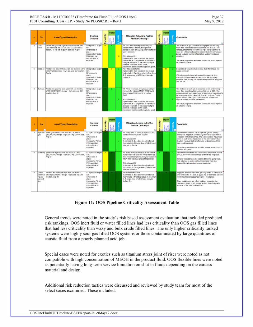
Figure 11: OOS Pipeline Criticality Assessment Table
General trends were noted in the study’s risk based assessment evaluation that included predicted risk rankings. OOS inert fluid or water filled lines had less criticality than OOS gas filled lines that had less criticality than waxy and bulk crude filled lines. The only higher criticality ranked systems were highly sour gas filled OOS systems or those contaminated by large quantities of caustic fluid from a poorly planned acid job.
Special cases were noted for exotics such as titanium stress joint of riser were noted as not compatible with high concentration of MEOH in the product fluid. OOS flexible lines were noted as potentially having long-term service limitation on shut in fluids depending on the carcass material and design.
Additional risk reduction tactics were discussed and reviewed by study team for most of the select cases examined. These included:
OOSlineFlushFillTimeline-BSEEReport-R1-9May12.docx

BSEE TA&R - M11PC00022 (Timeframe for Flush/Fill of OOS Lines) Page 38 F101 Consulting (USA), LP. - Study No PLGS02.R1 – Rev.1 May 9, 2012
• Short to midterm planned shut-in: Blowdown the system preferably, so that the majority of the line is at or below hydrostatic pressure. Then dose with additional MEOH and biocide before line goes OOS.
• Longer term Planned Shut-in: Flush line segment to be shut in and flushed of product and refill it with export grade crude oil like or dead oil with low CO2 content, or if applicable MEOH or glycol, or production fluids highly dosed with corrosion inhibitor (ie: 30 ppm and biocide). If a gas line, then fill with nitrogen or with large nitrogen blanket on production gas.
o The use of well-filtered untreated or treated seawater would be a last resort. Adding water to a gas system that is later restarted actually adds risk to the system than other options.
o Re circulating chemical injection cocktails in a longer-term OOS pipeline that is briefly brought back into service at least once a year is good practice. This refreshes the CI and biocide efficacy, distribution and helps flush out and disperse any bacteria colonies that may have been forming.
o Blowing the line pressure down – preferably to sub hydrostatic pressures- is effective in reducing leak consequence. Lower pressure will also help reduce chance of various H2S related cracking risks.
o Keeping bacteria out of the line by using well-filtered water when filling for hydrotest and by the use of periodic biocide chemical injection (ie: THPS) mixed into product stream.
o Maintain a good mix rate of corrosion inhibitor in the product (ie: MEOH, or LDHI).
o “Pickle” the line to extend the safe OOS timeline. Inert fluid flush and fill with export grade crude, dead oil, or other pipeline specific approved inert fluid like MEOH or glycol. For select gas lines, a nitrogen blanket may be a suitable alternate.
o Periodically flowing an OOS line for a few days to inject fresh corrosion inhibitors and re-mix them throughout the line should also help extend the safe OOS timeline.
Note that these tactics were suggested as method to extend OOS timeline for cases where the operator strongly expects to bring the pipeline back into service. These tactics where noted as potentially truly useful when in association with maintaining good long term integrity management of the system.
Proper consideration for any of the multi-dimensional variables such as mudslide or shipping lanes region locations, IM "quality" and other factors such as subsea service versus shallow water systems will need to be addressed by flowchart questionnaire approach for practicality on a case by case basis.
The study team supported the workshop findings in that a flowchart assessment approach to guide operators into determining what an appropriate option is for the various OOS line services, situations and line conditions was the practical way forward. Appendix A includes this flowchart.
OOSlineFlushFillTimeline-BSEEReport-R1-9May12.docx
BSEE TA&R - M11PC00022 (Timeframe for Flush/Fill of OOS Lines) Page 39 F101 Consulting (USA), LP. - Study No PLGS02.R1 – Rev.1 May 9, 2012
7. CONCLUSIONS & RECOMMENDATIONS
7.1.1 Conclusions
The existing 30CFR250.1006 one year rule along with local industry good practice appears to have worked successfully. No clear cases of OOS line internal microbiologically induced corrosion (MIC) being the root cause for a significant hydrocarbon leak or failed re-hydrotest were noted. However, in many cases the rule appears to be conservative or actually may add risk if a well kept gas line is brought back into service after a few months more than the one year rule allows. Further risk in the current rule can be seen when highly acidic or highly sour product filled lines are not flushed quickly. High risk service lines should have a mandatory quicker product flush than 1 year. The lack of continuity between the DOI one year rule and the international regulator’s risk based performance approach is significant. A risk based flowchart approach toward determining not just the timeline between flush and seawater fill, but when it is appropriate to flush and inert product fill was recommended. An alternate inert product fill interim approach is being recommended to enhance integrity and safety of OOS lines. Suggested timelines before flushing and filling a pipeline with seawater based on service and condition were based on feedback from the subject matter experts associated with this work. It should be noted that the owner/ operator or ROW holder is fully responsible for the integrity of their assets and should take a conservative approach toward protecting the environment from possible leaks. In all cases for having an extended timeline before flushing and filling with seawater, the owner/operator should demonstrate evidence of good line integrity management and confidence in its ability to safely hold pressure. Further the owner/operator should demonstrate a business case showing that the line will be brought back into service in a reasonable amount of time and not simply left as “idle iron” in the field.
7.1.2 Recommendations
The following list of recommendations was made regarding the care and disposition of out of service pipeline.
1. Inert fluid, sweet gas, bulk gas with minimal condensate, dead oil or export grade crude service lines were noted as having the least likelihood of developing corrosion based leaks. Assuming that documented evidence of proper line integrity management can be demonstrated, it was recommended that such lines be considered low criticality and considered for an extended OOS term before seawater flush, fill and pressure test actions are required. It was recommended that export grade or dead oil service lines are risk assessed more carefully based on their greater environmental consequence if external leaks occurred.
a. Suggested Process: To use export grade crude or dead oil as “pickling “ line fill fluid for an OOS pipeline, the lease holder may request a waiver extension from the 1 year limit to 3 years. Acceptance of this request would be recommended if:
OOSlineFlushFillTimeline-BSEEReport-R1-9May12.docx
i. Short term OOS cause is noted. For instance if the line was damaged due to hurricane or other damage where equipment delays have occurred.

BSEE TA&R - M11PC00022 (Timeframe for Flush/Fill of OOS Lines) Page 40 F101 Consulting (USA), LP. - Study No PLGS02.R1 – Rev.1 May 9, 2012
ii. Line fluid cleanliness. If recent product sampling illustrates that sulfate reducing bacteria (SRB) in the oil < 1,000 SRB units/ ml of fluid. The water separated from oil should be tested. Sampling should be done before export grade crude is used to displace the product.
2. Water injection lines were deemed low criticality because the product in them is treated seawater and would have negligible environmental impact if leaked and treated similar to bulk gas lines.
3. Bulk gas with condensate service lines were noted as having a medium likelihood of developing corrosion based leaks. Assuming that documented evidence of proper line integrity management can be demonstrated, it was recommended that such lines be considered medium criticality and only considered for an extended OOS term before seawater flush, fill and pressure test actions are required if suggested risk mitigation action for planned shut downs were carried out.
4. Bulk oil and highly sour service gas service lines were noted as having a high likelihood
of developing corrosion based leaks. Assuming that documented evidence of proper line integrity management can be demonstrated, it was recommended that such lines be considered high criticality.
a. Only non-sour, bulk oil service lines should be considered for an extended OOS term before seawater flush, fill and pressure test actions are required if suggested risk mitigation action for planned shut downs were carried out. Oily water mix lines may be classified as bulk oil in this case.
b. Highly sour service OOS lines should be inert fluid “pickled” as soon as possible and, or flushed and filled with seawater in a reduced period.
5. Proper flow line integrity (IM) management should include a process with a documented review of OOS system components and their service and repair history. The assessment of this IM process should be used to help finalize the appropriate time before seawater flush and fill is required. This process review should be in aligned with DNV-OS-F101 section C1100, A300, B300, C10, D100, D300, and E500.
6. It is envisioned that use of risk mitigation actions as noted in section 6.2.3 of this report will have a significant effect on the OOS associated timeline required before seawater flush and fill. These included OOS line depressurization, preventing or treating harmful bacteria, dosing with appropriate CI and periodic recirculation, and pickling the line segment with inert fluid such as dead oil, export grade crude, MEOH, or N2 blanket.
7. New build pipelines should be encouraged to be designed to be piggable when practical.
8. Good IM plans should to include topsides and other test sample monitoring of product for MIC bacteria as well as physical line inspections with focus on the riser.
9. An example flowchart process for alternate processing of OOS line requests for deviation requests from the one-year rule is shown in Appendix A. The approach is similar to that used in the ISO 12747’s flow chart for extended life justification. Suggested time limits also considered the idle iron issue and the 5-year rule on permanent decommissioning.
OOSlineFlushFillTimeline-BSEEReport-R1-9May12.docx
10. Use of a third party entity similar to a Certified Verification Agent (CVA) may be appropriate to help define acceptable integrity and pipeline condition for the specific pipelines requesting alternative treatment to the current 1 year rule.

BSEE TA&R - M11PC00022 (Timeframe for Flush/Fill of OOS Lines) Page 41 F101 Consulting (USA), LP. - Study No PLGS02.R1 – Rev.1 May 9, 2012
OOSlineFlushFillTimeline-BSEEReport-R1-9May12.docx
8. APPENDIX A – OOS FLUSH & FILL FLOW CHART
The workshop feedback and research study’s conclusions and recommendations indicated a very large number of variables exist for a given pipeline’s integrity. The key conditions of interest for the OOS timeline before a seawater flush and fill should be required narrowed down to defining the line’s overall and individual key components integrity condition, past and present service and its owner’s plans for use in the future.
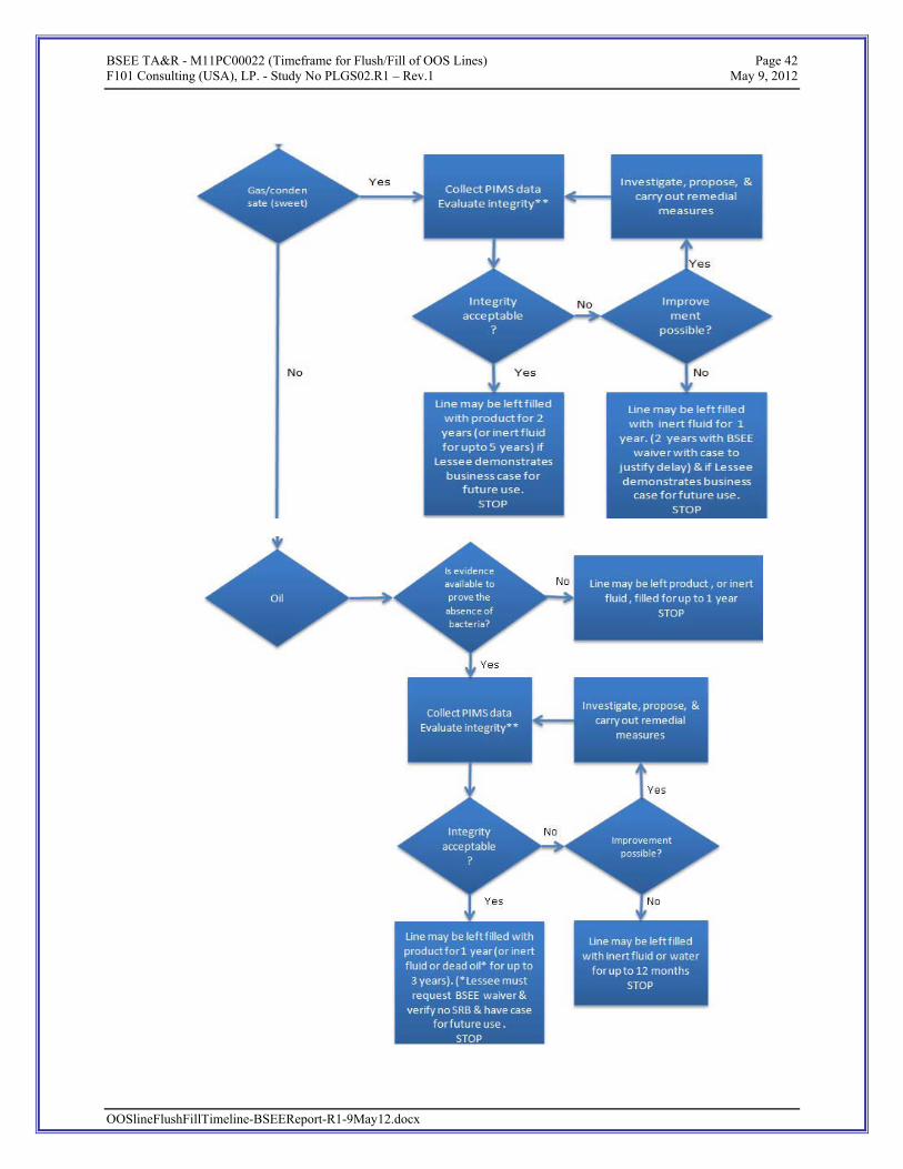
BSEE TA&R - M11PC00022 (Timeframe for Flush/Fill of OOS Lines) Page 42 F101 Consulting (USA), LP. - Study No PLGS02.R1 – Rev.1 May 9, 2012
OOSlineFlushFillTimeline-BSEEReport-R1-9May12.docx
BSEE TA&R - M11PC00022 (Timeframe for Flush/Fill of OOS Lines) Page 43 F101 Consulting (USA), LP. - Study No PLGS02.R1 – Rev.1 May 9, 2012
OOSlineFlushFillTimeline-BSEEReport-R1-9May12.docx
Notes:
1) Sour service defined in accordance with ISO 15156 / NACE MR-0175. (Let highly sour service mean H2S >100 ppm)
2) Integrity evaluation based on all data in PIMS. (If line has been left with acid for >48 hours, integrity is not acceptable)
3) Absence of bacteria if hydrotest water was treated, or if recent samples are available for proof.
4) Approved inert fluid fill option as option to leaving product. This will reduce risk or OOS line corrosion. (ie: export grade crude oil and dead oil use require BSEE waiver for extended line storage. Use of glycol, MEOH, or Nitrogen blanket should not require BSEE waiver.)