study the effect of serial inductance on reducing the
TRANSCRIPT
Tikrit Journal of Engineering Sciences (2018) 25 (3) 1 – 4 1
ISSN: 1813-162X (Print) ; 2312-7589 (Online)
Tikrit Journal of Engineering Sciences
available online at: http://www.tj-es.com
Ghanim Thiab Hasan 1, *
Muhamad Omar Salih 2
Ali Hlal Mutlaq 3 1 Oil & Minerals Engineering College
Tikrit University Salahaldeen Iraq
2 College of Engineering Tikrit University Salahaldeen Iraq
3 Technical College/ Kirkuk Kirkuk Iraq
Keywords:
Serial inductance
current harmonics distortion
bridge rectifier
A R T I C L E I N F O
Article history:
Received 05 March 2017
Accepted 17 April 2018
Available online 01 September 2018
Tik
rit
Jou
rna
l o
f E
ng
inee
rin
g
Sci
ence
s
Tik
rit
Jou
rnal
of
En
gin
eeri
ng S
cien
ces
Tik
rit
Jou
rnal
of
En
gin
eeri
ng
Sci
ence
s
Tik
rit
Jou
rna
l o
f E
ng
inee
rin
g
T
ikri
t
Jou
rna
l o
f E
ng
inee
rin
g S
cien
ces
Study the Effect of Serial Inductance on Reducing the Current Harmonic Distortion of Three-Phase Bridge Rectifier
A B S T R A C T
The aim of this paper is to analyze the influence of adding serial inductance in AC
side of the 3ph -6 pulse bridge rectifier on the reduction of harmonic distortion rate.
A simulated model with serial inductance was analyzed. The 3-phase 6-pulse diode
bridge rectifier was chosen because it corresponds to the operation of the 6-pulse
thyristor bridge rectifier at maximum load (while keeping the angle α = 0). Both the
total harmonic distortion (THDi) and the power factor (PF) for the circuit have been
measured. The results obtained of the THDi has been recorded for four values of
serial inductance and results was compared with the (IEEE 519-1992) standard.
Comparison results indicates that for values of inductive reactance (Xi) up to 67%
cause a reduction of THDi which is above the standard values, while for (Xi) more
than 67% cause a reduction in THDi within the acceptable standard level. Analyzing
of results prove that the adding of serial inductance at the AC side leads to good
reduction in harmonic distortion rate, but with some reduction in power factor value,
which results in some energy losses.
© 2018 TJES, College of Engineering, Tikrit University
DOI: http://dx.doi.org/10.25130/tjes.25.3.01
معدل الموجة الكاملة ثلاثي حزمة تيار دراسة تأثير الحث المتوالي على تقليل التشويه الحاصل في
الخلاصة
ي حزمة التيار المتردد ففي مدخل المقوم الجسري الثلاثي الطورعلى تقليل معدل التشوه التوافقي الحاصل الهدف من هذه البحث هو تحليل تأثير إضافة المحاثة المتوالية
زاوية ـــــــظ على الثايرستورات )مع الحفا 6دايودات لتوافقه مع شروط تشغيل المقوم الجسري المركب من 6باستخدام نموذج محاكاة لمقوم جسري ثلاثي الطور مكون من
α =0.) ( تم قياس كل من التشوه التوافقي الكليTHDi( وعامل القدرة )PF للدائرة لثلاث قيم )،تمت مقارنة النتائج مع والمحاثة لثلاث مرات زيادة قيمحيث تم مختلفة
الملف ٪ من قيمة ممانعة 67وح به لحد ( تبقى فوق المستوى المسمTHDiن قيمة )(. نتائج المقارنة تشيرإلى أTHDi( المسموح به لقيمة )IEEE 519-1992)المعيار
%(Xi،) ـاما عند زيادة قيمة ال%(Xi لاكثر من ذلك سيحصل انخفاض في معدل ال )THDi شير الى أن إضافة وهو ضمن المستوى القياسي المقبول. تحليل النتائج ي بنسبة
ة.المقوم الجسري الثلاثي الطور يؤدي إلى انخفاض جيد في معدل التشوه التوافقي مع بعض الخسائر في قيمة عامل القدر في مدخلالمحاثة المتوالية
1. INTRODUCTION
Advances in semiconductor fabrication technology
have resulted in the development of the Variable
Frequency induction motors drive (VFIMD), which are
used in many applications such as air conditioning, fans,
water treatment pumps, textile works, rolling mills etc. The
more practical VFIMD method is direct torque control
because it offers better performance than other control
methods [1]. The Direct Torque drive technique is used in
* Corresponding author: E-mail : [email protected]
the power source inverter, which is mainly powered by 6-
pulse bridge diode rectifier, and insulated gate bipolar
transistors (IGBT) [2]. The most common disadvantage of
the Rectifier with a 6-pulse bridge diode is the small power
factor of the current harmonics in the mains. Harmonic
current of the power source causes harmonic polluted
voltages at the common coupling point (PCC) and,
therefore, unwanted voltage distortion will be created in
the circuit loads [3]. The total harmonic distortion
harmonic current values introduced into the supply system
Ghanim Thiab Hasan et al. / Tikrit Journal of Engineering Sciences 25 (3) 2018 (1-4) 2
by a non-linear load, such THD must be kept within the
standard limits.
Many input wave-forming techniques have been
suggested for reducing the total harmonic distortion level,
which can be classified in both active and passive methods.
The passive filter often used to eliminate the ripple content
from the output, but they create a rectangular wave of input
current that contains higher total harmonic distortion [4].
Harmonic distortions can cause many problems,
including, equipment overheating, operating errors in
protective relays, communications equipment malfunc-
tions, etc. Harmonic frequencies represent the multiple of
their fundamental frequency. When the harmonic level
exceeds the limit, it is necessary to reduce it to ensure
satisfactory operation of the system [5]. An interesting
design that presented by M. Peterson and B. Singh which
come to result that under reduced loading conditions, the
firing angle increased, which led to higher THD and lower
efficiency of the system [6]. Authors proposed a dynamic
control scheme that involves simultaneous and selective
control of firing angle and the pulse count of converter. For
pulse count control, an appropriate 6-pulse rectifier or pair
of 6-pulse rectifiers is disabled or enabled depending on the
current loading. In their design D. C. Ku were tried to
reduce the power harmonics in the integrated power system
by using a Multi-pulse converters and passive filtering
which come to good results in THDi reduction [7].
2. MEASUREMENT OF TOTAL HARMONIC DISTORTION
The total harmonic distortion value must be kept
under the international recommended standard level. The
most well-known standard is the IEEE 519-1992 standard
level. According to this standard, each harmonic should be
less than or equal to 3% and the THD must be lower than
or equal to 5% [8].
The THD represent the summation of all harmonics
of voltage or input current waveform compared with the
fundamental component of this voltage or input current,
which can be calculated as follows [9]:
𝑇𝐻𝐷𝑣 =√𝑉22 + 𝑉32 + 𝑉42 + ⋯ . . +𝑉𝑛2
𝑉1
× 100% (1)
𝑇𝐻𝐷𝑖 =√𝐼22 + 𝐼32 + 𝐼42 + ⋯ . . +𝐼𝑛2
𝐼1
× 100% (2)
where
THDi Total high distorted input current.
THDv Total high distorted supply voltage.
Harmonics produced by nonlinear loads can be
reduced by some methods such as, adding passive filter
reactor in AC side, serial line inductance in AC side or DC
filter in DC side [9]. This paper was interested in studying
and analysis the impact of adding a serial inductor in AC
side of a 3-phase 6-pulse diode bridge on the reduction of
current THD. The 3-phase 6-pulse diode bridge rectifier
was chosen due to it corresponds to the operation of the 6-
pulse thyristor bridge rectifier at maximum load (with
keeping the angle α = 0). When current through the
inductor changes, some voltage will be induced across its
terminals with opposite direction of the applied voltage
WHICH LEED to reduce the THD [10].
Measurements are conducted by gradually increasing the
series inductance value in the AC side. The serial inductive
reactance (X%) was used in the analysis instead of
inductance L and it can be calculated as follows [11]:
𝑋% =𝑙1 2𝜋 𝑓 𝐿
𝑈× 100% =
𝑙1 𝑋𝐿
𝑈× 100% (3)
where
I1 Rated current of first harmonic, (A).
L Phase inductance, (H).
U Phase voltage, (V).
f Frequency, (Hz)
X Phase reactance, (Ω)
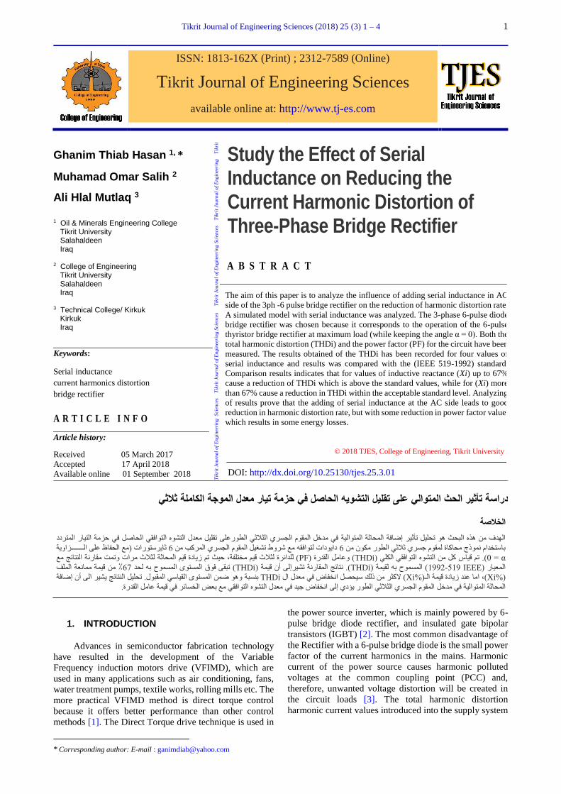
The simulation model was performed using Simulation
work is done utilizing the MATLAB / Simulink
programming results have been displayed to accept the
hypothesis. Fig. 1 shows the simulation model of 3ph-6
pulse bridge rectifier.
Fig. 1. Simulation model of 3ph-6 pulse bridge rectifier.
3. RESULTS AND DISCUSSION
Measurement started with measuring the THD
current in the circuit without adding serial inductance, then
the measurement is repeated with adding serial inductance
for three different. Results of serial inductive reactance
(X%) are indicated in Table 1.
Table 1
Results of decreasing the (THDi) due to increasing the
serial inductance (X%).
X% THDi
(%)
Harmonic
current (Ii%) cosφ power
factor
0.0 29.16 23 1.0 1.0
8.7 23.70 21 0.9 0.96
41.9 9.83 7 0.8 0.83
67.5 4.61 4 0.7 0.68
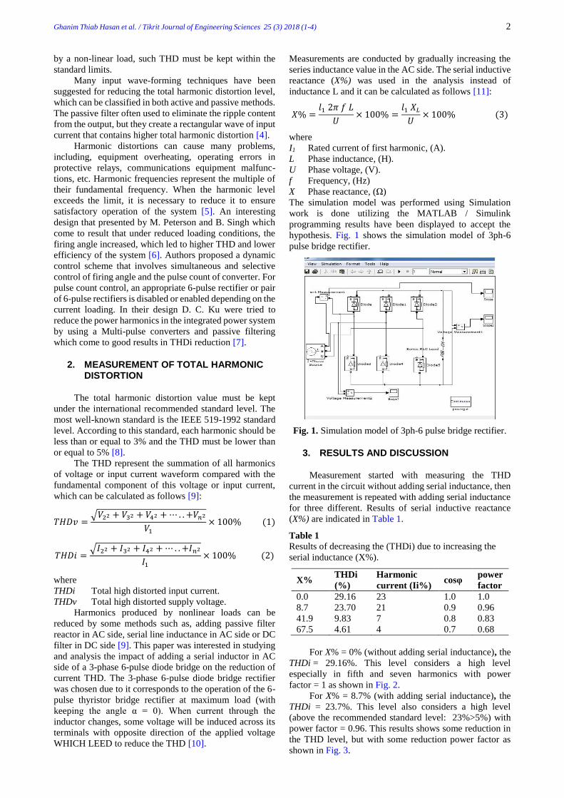
For X% = 0% (without adding serial inductance), the
THDi = 29.16%. This level considers a high level
especially in fifth and seven harmonics with power
factor = 1 as shown in Fig. 2.
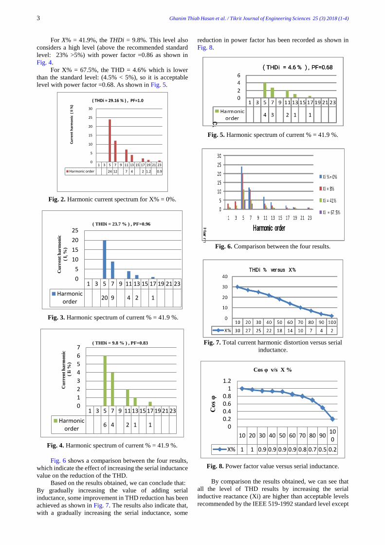
For X% = 8.7% (with adding serial inductance), the
THDi = 23.7%. This level also considers a high level
(above the recommended standard level: 23%>5%) with
power factor = 0.96. This results shows some reduction in
the THD level, but with some reduction power factor as
shown in Fig. 3.
3 Ghanim Thiab Hasan et al. / Tikrit Journal of Engineering Sciences 25 (3) 2018 (1-4)
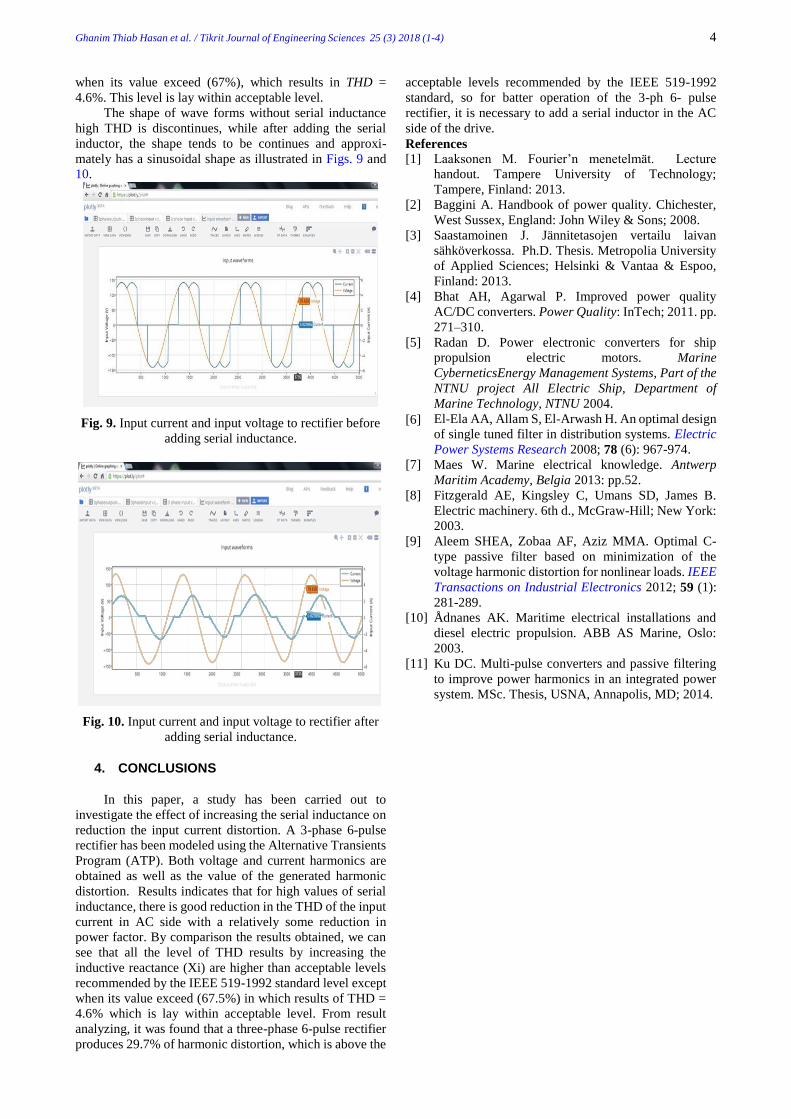
For X% = 41.9%, the THDi = 9.8%. This level also
considers a high level (above the recommended standard
level: 23% >5%) with power factor =0.86 as shown in
Fig. 4.
For X% = 67.5%, the THD = 4.6% which is lower
than the standard level: (4.5% < 5%), so it is acceptable
level with power factor =0.68. As shown in Fig. 5.
Fig. 2. Harmonic current spectrum for X% = 0%.
Fig. 3. Harmonic spectrum of current % = 41.9 %.
Fig. 4. Harmonic spectrum of current % = 41.9 %.
Fig. 6 shows a comparison between the four results,
which indicate the effect of increasing the serial inductance
value on the reduction of the THD.
Based on the results obtained, we can conclude that:
By gradually increasing the value of adding serial
inductance, some improvement in THD reduction has been
achieved as shown in Fig. 7. The results also indicate that,
with a gradually increasing the serial inductance, some
reduction in power factor has been recorded as shown in
Fig. 8.
Fig. 5. Harmonic spectrum of current % = 41.9 %.
Fig. 6. Comparison between the four results.
Fig. 7. Total current harmonic distortion versus serial
inductance.
Fig. 8. Power factor value versus serial inductance.
By comparison the results obtained, we can see that
all the level of THD results by increasing the serial
inductive reactance (Xi) are higher than acceptable levels
recommended by the IEEE 519-1992 standard level except
1 3 5 7 9 11 13 15 17 19 21 23
Harmonic order 24 12 7 4 2 1.2 0.9
0
5
10
15
20
25
30
Cu
rren
t h
arm
on
ic (
Ii %
)
( THDi = 29.16 % ) , PF=1.0
1 3 5 7 9 11 13 15 17 19 21 23
Harmonicorder
20 9 4 2 1
0
5
10
15
20
25
Cu
rren
t h
arm
on
ic
( I i
%)
( THDi = 23.7 % ) , PF=0.96
1 3 5 7 9 11 13 15 17 19 21 23
Harmonicorder
6 4 2 1 1
0
1
2
3
4
5
6
7
Cu
rren
t h
arm
on
ic
( Ii
%)
( THDi = 9.8 % ) , PF=0.83
10 20 30 40 50 60 70 80 90100
X% 1 1 0.9 0.9 0.9 0.9 0.8 0.7 0.5 0.2
00.20.40.60.8
11.2
Co
s φ
Cos φ v/s X %
Ghanim Thiab Hasan et al. / Tikrit Journal of Engineering Sciences 25 (3) 2018 (1-4) 4
when its value exceed (67%), which results in THD =
4.6%. This level is lay within acceptable level.
The shape of wave forms without serial inductance
high THD is discontinues, while after adding the serial
inductor, the shape tends to be continues and approxi-
mately has a sinusoidal shape as illustrated in Figs. 9 and
10.
Fig. 9. Input current and input voltage to rectifier before
adding serial inductance.
Fig. 10. Input current and input voltage to rectifier after
adding serial inductance.
4. CONCLUSIONS
In this paper, a study has been carried out to
investigate the effect of increasing the serial inductance on
reduction the input current distortion. A 3-phase 6-pulse
rectifier has been modeled using the Alternative Transients
Program (ATP). Both voltage and current harmonics are
obtained as well as the value of the generated harmonic
distortion. Results indicates that for high values of serial
inductance, there is good reduction in the THD of the input
current in AC side with a relatively some reduction in
power factor. By comparison the results obtained, we can
see that all the level of THD results by increasing the
inductive reactance (Xi) are higher than acceptable levels
recommended by the IEEE 519-1992 standard level except
when its value exceed (67.5%) in which results of THD =
4.6% which is lay within acceptable level. From result
analyzing, it was found that a three-phase 6-pulse rectifier
produces 29.7% of harmonic distortion, which is above the
acceptable levels recommended by the IEEE 519-1992
standard, so for batter operation of the 3-ph 6- pulse
rectifier, it is necessary to add a serial inductor in the AC
side of the drive.
References [1] Laaksonen M. Fourier’n menetelmät. Lecture
handout. Tampere University of Technology;
Tampere, Finland: 2013.
[2] Baggini A. Handbook of power quality. Chichester,
West Sussex, England: John Wiley & Sons; 2008.
[3] Saastamoinen J. Jännitetasojen vertailu laivan
sähköverkossa. Ph.D. Thesis. Metropolia University
of Applied Sciences; Helsinki & Vantaa & Espoo,
Finland: 2013.
[4] Bhat AH, Agarwal P. Improved power quality
AC/DC converters. Power Quality: InTech; 2011. pp.
271–310.
[5] Radan D. Power electronic converters for ship
propulsion electric motors. Marine
CyberneticsEnergy Management Systems, Part of the
NTNU project All Electric Ship, Department of
Marine Technology, NTNU 2004.
[6] El-Ela AA, Allam S, El-Arwash H. An optimal design
of single tuned filter in distribution systems. Electric
Power Systems Research 2008; 78 (6): 967-974. [7] Maes W. Marine electrical knowledge. Antwerp
Maritim Academy, Belgia 2013: pp.52.
[8] Fitzgerald AE, Kingsley C, Umans SD, James B.
Electric machinery. 6th d., McGraw-Hill; New York:
2003.
[9] Aleem SHEA, Zobaa AF, Aziz MMA. Optimal C-
type passive filter based on minimization of the
voltage harmonic distortion for nonlinear loads. IEEE
Transactions on Industrial Electronics 2012; 59 (1):
281-289.
[10] Ådnanes AK. Maritime electrical installations and
diesel electric propulsion. ABB AS Marine, Oslo:
2003.
[11] Ku DC. Multi-pulse converters and passive filtering
to improve power harmonics in an integrated power
system. MSc. Thesis, USNA, Annapolis, MD; 2014.