studying the impact of the organizational structure on
TRANSCRIPT

Seediscussions,stats,andauthorprofilesforthispublicationat:https://www.researchgate.net/publication/285406861
StudyingtheImpactoftheOrganizationalStructureonAirlineOperationsControl
CHAPTER·DECEMBER2015
DOI:10.1016/B978-0-12-397041-1.00006-6
READ
1
3AUTHORS,INCLUDING:
AntónioJ.M.Castro
LIACC
30PUBLICATIONS71CITATIONS
SEEPROFILE
EugénioOliveira
UniversityofPorto
315PUBLICATIONS1,734CITATIONS
SEEPROFILE
Allin-textreferencesunderlinedinbluearelinkedtopublicationsonResearchGate,
lettingyouaccessandreadthemimmediately.
Availablefrom:AntónioJ.M.Castro
Retrievedon:11January2016

Studying the Impact of the OrganizationalStructure on Airline Operations Control
Nuno Machado, Antonio J. M. Castro, and Eugenio Oliveira
LIACC/NIADR, FEUP, DEI, University of Porto,[email protected],
http://www.liacc.up.pt/
Abstract. This paper introduces work practice modeling and simula-tion as a mean to assess and evolve the airline organizational structureperformance. It departs from the empirical knowledge conveyed throughinterviews with airline operators and builds an analytical infrastructuregeared towards evaluating the current and hypothetical organizationalstructures. To better reproduce the operational control challenges facedby airline companies it uses real pre and post operational data containingscheduled flights, delay codes and aircraft and crew rosters. By the end ofthe research study, the simulation of the same operational scenario acrossfour distinct organizational structures demonstrated improvements up to15% in disruption handling time and up to 21% in collaborator stress.
Keywords: disruption management, operations recovery, airline opera-tions, multi-agent systems, simulation based
1 Introduction
An organizational structure might be regarded as a set of entities collectivelycollaborating and contributing toward one common goal. The employees workingin an assembly line or a rescue team are examples of organizational structures.Nowadays, with the increasing complexity of goods and services, and competingin a globalized world, organizations require tuned work systems, involving humancapital interwoven with the latest technological innovations.
Evolving an established organizational structure is often daunting when itis behind the core mission of a business or when it operates uninterruptedly.In these cases, software simulations are an invaluable tool to explore new workpractices, information flows or even decision making processes. Modeling andsimulating complete or small portions of critical workflows, makes it feasible tocollect a set of metrics as well as introducing organizational transformations.Brought together, these factors allow for organizational performance assessmentand evolution.
The work presented in this paper is founded on such observations and aimedat proposing improvements to the operational control within a real airline com-pany. To accomplish such aim, we had to use a real airline company as case study.

2
TAP, the major portuguese air carrier, agreed to participate on such project andprovided useful information and data.
As any simulation-based research, this study involved three main stages thatwill be discussed in the following sections. First, we had to unveil the entitiesinvolved on airline operations such as facilities, supporting systems, human col-laborators and their main activities. Next, we used Brahms, a multi-agent systemfeaturing the BDI model and its own agent-oriented programming language tomodel and simulate the airline empirical concepts. Finally, we collected a setof metrics, introduced organizational structure modifications and established aquantitative comparison among the latter.
2 Background
First and foremost we tried to get some background information or discovertargeted literature about other initiatives regarding airline operations controlsimulation but at no avail.
Following this, to the best of our knowledge we were the first to simulate theAirline Operational Control Centre (AOCC) organizational structure in order tostudy its impact in airline disruption handling. Because of that it is difficult tocompare our approach with others. Nevertheless, in this section, we would liketo provide some background regarding work systems modeling and simulationand, also, about AOCC organization and some work related with disruptionmanagement.
2.1 Work Systems Modeling and Simulation
A work system involves people engaging in activities over time. Human partic-ipants might not just interact with each other, but also with machines, tools,documents, and other artifacts [1].
The activities performed often produce goods, services or data. There are twodifferent approaches when it comes to designing or improving systems: machine-centered and human-centered [2]. The former is usually accomplished through abusiness process reengineering approach [3] based on business process flow anal-ysis focused on work products. The latter also takes into account how the peoplein the organization actually prefer to work [4]. Unlike the machine-centered ap-proach, which neglects human communication, collaboration, workspaces, prob-lem solving and learning; the human-centered approach analyze human activi-ties, work processes or tasks, comprehensively and chronologically throughoutthe day [5].
The human-centered work system design approach is based on modeling andsimulating work practices: what people actually do, rather their outcomes. Thisway, it is possible to understand the effects of human behaviors in different placesand times, details often omitted in a product-oriented task analysis. In the end,besides the traditional system workflow, human-centered approach might also
3
propose some work system transformations, including different tools, resources,locations or scheduling.
Aiming at using a human-centered approach to model and simulate our orga-nizational structures, Brahms [6] was adopted as modeling and simulating tool.It follows a holistic approach to systems modeling. By developing formal modelsof people’s behavior at the activity level, it is possible to determine the impactof these actions on the whole system.
Besides its own agent-oriented programing language, Brahms contains somepre-defined model components that make it straightforward to implement realityconcepts:
– Agent/Groups: to model the human collaborator;– Objects: for the computerized systems;– Geographies: used to indicate the location of facilities;– Activity: to express the agent behaviours;– Timing/Workframes: used to model activity duration.
Brahms does not provide real-time visual feedback of a running simulation.Therefore this deficiency had to be address through the development of a visu-alization of the simulated airline.
2.2 Airline Operational Control Centre Organization
The main role of the AOCC is to monitor the conformance of flight activity ac-cording to the previously defined schedule. The occurrence of some unexpectedevents might prevent operations to take place as planned, such as aircraft mal-function, crew delays, crew members absence, etc.
Following this, the AOCC is a human decision system composed by teamsof experts specialized in solving the described problems. Teams act under thesupervision of an operational control manager and their goal is to restore airlineoperations in the minimum frame and at a minimum cost.
According to Castro [7], there are three main AOCC organizations:
– Decision Centre: the aircraft controllers share the same physical space.The other roles or support functions (crew control, maintenance service,etc.) are in a different physical space. In this type of Collective Organizationall roles need to cooperate to achieve the common goal.
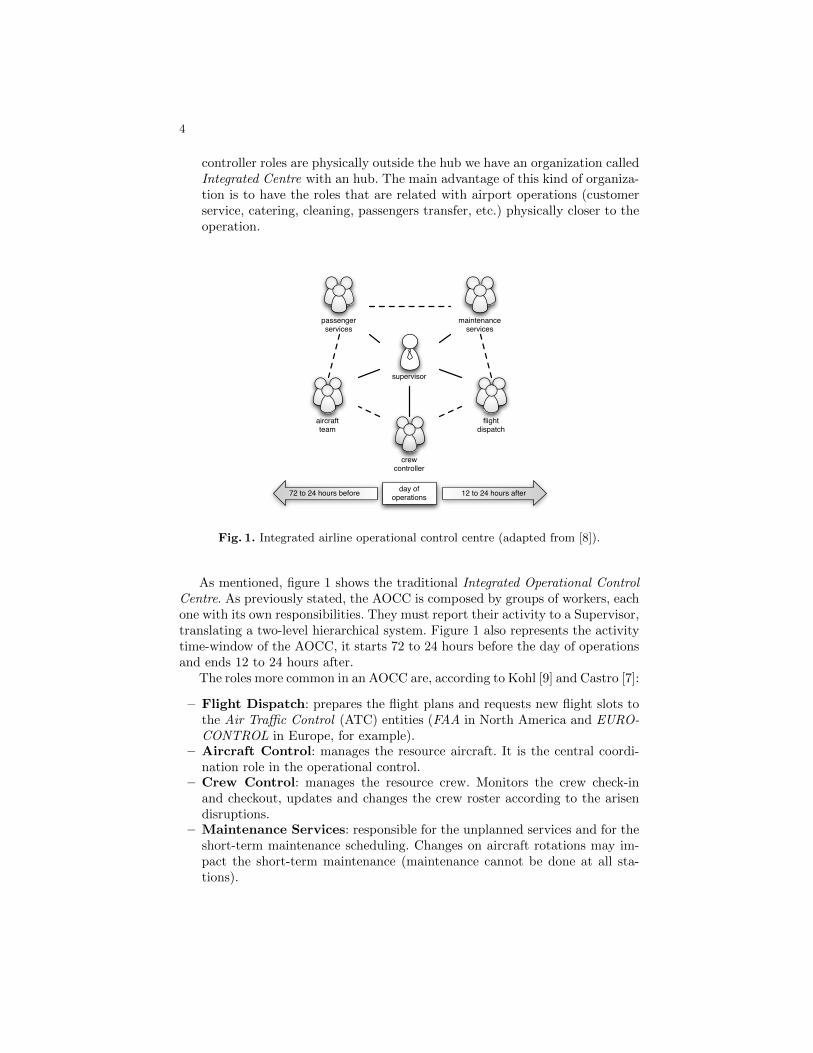
– Integrated Centre: all roles share the same physical space and are hier-archically dependent of a supervisor. For small companies we have a SimpleHierarchy Organization. For bigger companies we have a MultidimensionalHierarchy Organization. Figure 1 shows an example of this kind of AOCCorganization.
– Hub Control Centre: most of the roles are physically separated at theairports where the airline companies operate an hub. In this case, if the air-craft controller role stays physically outside the hub we have an organizationcalled Decision Centre with an hub. If both the aircraft controller and crew
4
controller roles are physically outside the hub we have an organization calledIntegrated Centre with an hub. The main advantage of this kind of organiza-tion is to have the roles that are related with airport operations (customerservice, catering, cleaning, passengers transfer, etc.) physically closer to theoperation.
passenger services
maintenance services
aircraftteam
flightdispatch
crewcontroller
supervisor
12 to 24 hours after72 to 24 hours before day of operations
Fig. 1. Integrated airline operational control centre (adapted from [8]).
As mentioned, figure 1 shows the traditional Integrated Operational ControlCentre. As previously stated, the AOCC is composed by groups of workers, eachone with its own responsibilities. They must report their activity to a Supervisor,translating a two-level hierarchical system. Figure 1 also represents the activitytime-window of the AOCC, it starts 72 to 24 hours before the day of operationsand ends 12 to 24 hours after.
The roles more common in an AOCC are, according to Kohl [9] and Castro [7]:
– Flight Dispatch: prepares the flight plans and requests new flight slots tothe Air Traffic Control (ATC) entities (FAA in North America and EURO-CONTROL in Europe, for example).
– Aircraft Control: manages the resource aircraft. It is the central coordi-nation role in the operational control.
– Crew Control: manages the resource crew. Monitors the crew check-inand checkout, updates and changes the crew roster according to the arisendisruptions.
– Maintenance Services: responsible for the unplanned services and for theshort-term maintenance scheduling. Changes on aircraft rotations may im-pact the short-term maintenance (maintenance cannot be done at all sta-tions).
5
– Passenger Services: decisions taken on the AOCC will have an impact onpassengers. The responsibility of this role is to consider and minimize theimpact of the decisions on passengers. Typical this role is performed on theairports and for bigger companies is part of the HCC organization.
2.3 Disruption Management
Disruption Management [9], also known as Operations Recovery, is the processcarried out by the AOCC when an unexpected problem prevents a flight tooperate as planned.
The first overview of the state-of-the-practice in operations control centers inthe aftermath of irregular operations was provided by Clarke [10]. In his study,besides an extensive review over the subject, he proposes a decision frameworkthat addresses how airlines can re-assign aircraft to scheduled flights after adisruptive situation.
Currently, the most thoroughly analysis of the discipline is presented by Kohlet al. [11] where their conclusions are supported by the DESCARTES project,a large-scale airline disruption management research and development studysupported by European Union.
Other authors propose more general perspectives regarding disruption man-agement. Yu and Qi [12] analyze airline disruption management from differentangles: crew and aircraft recovery; and applied to other fields as well: machinescheduling and supply chain coordination. Given the large scope of their work,airline operations recovery are not particularly detailed.
On the other hand, Ball et al. [13] give insight into the infrastructure and con-straints of airline operations, as well as the air traffic flow management methodsand actions. Simulation and optimization models for aircraft, crew and passengerrecovery are also discussed. Furthermore, the authors give an excellent survey ofthe airline schedule robustness as a proactive alternative to recovery, includingmodel descriptions and a literature review.
From the mentioned studies it is clear a tendency to consider the disruptionmanagement problem as twofold: aircraft recovery and crew recovery. For eachtype of recovery several solution approaches were proposed based on differentmethodologies.
An in-depth and comprehensive review over the most relevant studies andmethodologies used in disruption management is presented by Clausen et al. [14].They not only explain the most traditional approaches, such as Connection, TimeLine and Time Band Networks, based on the scheduled aircraft and crew rostersbut also mention newer and innovative research studies.
While the vast majority of the publications use integer programming solutionmethods to solve the aircraft recovery problem, the most recent works apply somemetaheuristics to the problem, such as described by Andersson [15] and Liu etal. [16].
Moving to crew recovery, the majority of publications formulate the crewrecovery problem under assumption that the flight schedule is recovered beforethe crew re-scheduling decisions are made, thereby following the hierarchical
6
structure of the disruption recovery in practice. These publications include Weiet al. [17], Guo [18] and Nissen and Haase [19].
For instance, from the list of authors presented in the last paragraph, Weiet al. [17] model the crew pairing repair problem as an integer multicommoditynetwork flow problem on a Connection Network. The challenge is to repair thepairings that are broken and the objective is to return the entire system to theoriginal schedule as soon as possible while minimizing the operational cost.
Something interesting about Nissen and Haase [19] research is its foundingon European reality. They propose a duty-based formulation for the crew re-covery problem, which is especially well suited for solving the crew disruptionfor European airlines, as these, contrary to the North American airlines, employfixed monthly crew rates, which should be taken into consideration when solvinga crew disruption.
Finally, Castro and Oliveira [8] pioneer an approach that not only accountsfor the aircraft and crew perspectives but also considers passengers. An imple-mentation of an intelligent and distributed multi-agent system (MAS) representsthe operations control center of an airline. MAS includes a crew recovery agent,an aircraft recovery agent and a passenger recovery agent. They use concepts ofdirect and qualitative cost to determine solutions for the disruption problem.
3 Empirical Airline Operations
The airline operations start way before the actual flight day as they require thescheduling of flights in advance. Then several stages emerge such as the revenuemanagement, aircraft and crew rosters, and so on [8]. This is usually known asthe Airline Scheduling Problem [20].
When the day of operations arrives, unexpected events may prevent flightsto depart as planned and the airline specialists must address those situations.This is known as the disruption management problem.
Our study is about organizational structures of the AOCC on the contextof the day of operations, not to the disruption management algorithms and/orprocesses that are used to solve the disruptions. For that, we need to knowthe workflows before and after that stage the disruption, i.e., which are theunexpected events, who detects such events, how the airline specialists knowabout them and who is notified of putative solutions.
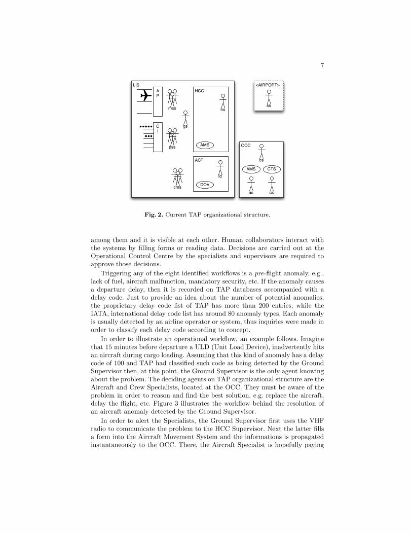
In order to simulate such scenario we needed to know the entities involved onairline operations. Figure 2 clearly depicts those entities and their geo-location.Squares represent facilities and ellipses computerized systems. Table 1 describeseach of the entities’ labels.
With a big picture of the current TAP organizational structure and its com-ponents, an in-depth understanding about the workflows as well as related ac-tivities was essential. Eight workflows and activities were identified.
Concerning the activities, across the organizational structure, informationis conveyed by means of VHF radios or telephones. Since the computerizedsystems share the same network, information is instantaneously synchronized
7
LISHCC
ACT
OCC
DOV
AMS
AMS CTS
as
<AIRPORT>AP
CI
os
cs
fd
sshs
cms
pss
mss
gs
Fig. 2. Current TAP organizational structure.
among them and it is visible at each other. Human collaborators interact withthe systems by filling forms or reading data. Decisions are carried out at theOperational Control Centre by the specialists and supervisors are required toapprove those decisions.
Triggering any of the eight identified workflows is a pre-flight anomaly, e.g.,lack of fuel, aircraft malfunction, mandatory security, etc. If the anomaly causesa departure delay, then it is recorded on TAP databases accompanied with adelay code. Just to provide an idea about the number of potential anomalies,the proprietary delay code list of TAP has more than 200 entries, while theIATA, international delay code list has around 80 anomaly types. Each anomalyis usually detected by an airline operator or system, thus inquiries were made inorder to classify each delay code according to concept.
In order to illustrate an operational workflow, an example follows. Imaginethat 15 minutes before departure a ULD (Unit Load Device), inadvertently hitsan aircraft during cargo loading. Assuming that this kind of anomaly has a delaycode of 100 and TAP had classified such code as being detected by the GroundSupervisor then, at this point, the Ground Supervisor is the only agent knowingabout the problem. The deciding agents on TAP organizational structure are theAircraft and Crew Specialists, located at the OCC. They must be aware of theproblem in order to reason and find the best solution, e.g. replace the aircraft,delay the flight, etc. Figure 3 illustrates the workflow behind the resolution ofan aircraft anomaly detected by the Ground Supervisor.
In order to alert the Specialists, the Ground Supervisor first uses the VHFradio to communicate the problem to the HCC Supervisor. Next the latter fillsa form into the Aircraft Movement System and the informations is propagatedinstantaneously to the OCC. There, the Aircraft Specialist is hopefully paying

8
Table 1. Organizational structure concepts.
Facilities
ACT Crew Terminal
AP Aircraft Parking
CI Passenger Check-In
HCC Hub Control Centre
LIS Lisbon Airport
OCC Operational Control Centre
Computerized Systems
AMS Aircraft Movement System
CTS Crew Tracking System
DOV Flight Operations Portal
Human Collaborators
as Aircraft Specialist
cms Crew Members
cs Crew Specialist
fd Flight Dispatcher
gs Ground Supervisor
hs HCC Supervisor
mss Maintenance Services
os OCC Supervisor
pss Passenger Services
ss Station Supervisor
attention to the screen and becomes aware of the problem. He reasons about theproblem and after reaching a conclusion inputs it into the AMS, being replicatedto the CTS. Now it is the turn of the Crew Specialist. Mandating or not somecrew assignment changes, the Crew Specialist is required to evaluate, take actionand confirm the solution suggested by the Aircraft Specialist through the CTSterminal. His input will be readily synchronized, once again, with the AircraftMovement System, making it available to both OCC Supervisor and HCC Su-pervisor. As the main character on the Operational Control Centre, the OCCSupervisor is required to ratify the decisions proposed by the Specialists, whilethe Hub Control Centre Supervisor uses the VHF radio again to communicatechanges to the Ground Supervisor.
All the activities above require time to perform. TAP was questioned aboutthe duration of such activities and, while a definite answer was impossible,it provided minimum and maximum time intervals for each activity. At thispoint we understood that communications by phone take, on average, more timethan VHF radio transmissions as they are usually concerned with more complexanomalies.

9
asAMShs CTS cs osgs
Fig. 3. Workflow triggered by an AC anomaly detected by Ground Supervisor.
4 Organizational Structure Performance Assessment
This section intends to suppress the lack of information regarding the organi-zational structure simulation by presenting the main features of Brahms, themodeling and simulating tool that introduces a new human-centered computingparadigm. In order to accomplish this, we will first draw a big picture of the sim-ulation system as a whole justifying the use of certain technologies and pointingout additional contributions to the communities behind those technologies. Next,we will explain how Brahms greatly improved the experience of modeling theworkflows on TAP. Finally, a subsection will also be dedicated to expose someaspects of a visualization module developed to allow a better understanding ofthe concepts being simulated.
4.1 Background and Overall Simulation Architecture
As referred during introduction, the main goal of this research study was tosimulate the operational control on a real airline company. Obviously, simplycreating a model of such reality and mimic its intrinsic features would be ofarguable interest so we aimed at, thereafter, propose changes that would lead tomore efficient activities and workflows.
The empirical observations listed in section 3, made us aware of the reality inTAP, our case study airline company. We soon noticed that we would be treatinga case that falls into the popular business process reengineering paradigm.

10
Following this, we had to adopt a simulation tool that would simplify themodeling of the concepts related to our airline company while at the same timefeatured some business process reengineering capabilities. Meeting this require-ments was Brahms [6] the Business Redesign Agent-Based Holistic ModelingSystem.
Although some theoretical information was already presented about Brahmson the Background, it worths point out some technical information about thissystem for the purpose of clarify certain options or side activities carried outalong this study.
First and foremost, Brahms is a Multi-Agent System featuring the BDI,Beliefs, Desires, Intentions, architecture 1. While these characteristics are notenough to distinguish it from many other simulation engines, Brahms is cur-rently being developed by the Brahms Team at NASA Ames Research Center incollaboration with the Carnegie Mellon University and it has been successfullyused in NASA’s Mission Control, to automate human tasks for the InternationalSpace Station. Its source code is proprietary but NASA freely distributes it forresearch purposes only.
At this point, we simply thought that if Brahms was enough for NASA itwould certainly suit our needs. After further inspecting the features provided byBrahms, we noticed that it was a much more advanced tool than other Multi-Agent Systems that we knew about. It sports its own agent-oriented program-ming language, adds up some human-centered computing concepts and has itsown production rules system.
The characteristics above ought to require an additional effort in implement-ing our airline company but we decided to take the challenge. Another featurelacking in Brahms is the ability to visualize the concepts being simulated. Whilethis functionality was not required to get a quantitative comparison of differentorganizational structures, it was regarded as an educational and clarifying wayof understanding the operations carried out in an airline company.
Being mostly characterized as an academia or scientific tool, Brahms lacks awide user community, where one may get models, code examples or help. Despiteof that, it is thoroughly documented and their creators lead a discussion groupto assist early-adopters.
As Brahms runs in a closed virtual machine, the first contact with the sim-ulator community intended to inquiry about the possibilities of developing avisualization of a running simulation. While the primary approach would beto interpret a set of output files post-simulation, Brahms features a Java API(JAPI) allowing for environment expansion and control.
Interacting with JAPI would be roughly the same as interacting with a javaapplication therefore we decided that our visualization would be built-in in theanalytical infrastructure and use the latest advancements in browser technology.
Figure 4 depicts the components and architecture beneath the simulationportion of our study. While this section is not meant to be too technical, other
1 Software model that implements the main aspects of Michael Bratman’s theory ofhuman practical reasoning.

11
analyticalinfrastructure
BRAHMScore
NETTY
JAPI
wsockets server
BROWSERProcessing javascript
engine
websocketsprotocol
inputoutput
Fig. 4. Overall simulation architecture and components.
aspects of figure 4 require further inspection. Starting from the beginning, thehuman user has the ability to interact with the analytical infrastructure througha browser. Given the set of technologies used, it is important to emphasize that atthe time of writing, the only browser that supports our infrastructure was GoogleChrome. Nevertheless, with the fast technological evolution, it is likely in thenear future other major browsers start to implement the technical innovationsemployed by our simulations.
Moving down in figure 4, the browser portion of the simulation architecturecontains the visualization module. It is mainly composed of two interwoven parts:the “javascript engine” and “processing”. The former handles all the communi-cations with the “websockets server”, discussed soon, decoding the incomingmessages and controlling “processing” animations.
Processing is widely used in the scientific and academic field given its abilityto create powerful representations of large sets of data. While the original Pro-cessing is based and to be used with the Java programming language, consideringour browser requirements we had to use a javascript port of the language.
The BROWSER component also allows for simulation control, that is, start-ing, pausing and stop the simulation. The visualization module will be describedon subsection 4.3, so at this point it just matters to understand we are in presenceof a distributed infrastructure where messages come in, go out and an animationof the simulated theatre is displayed in-between.
12
The “websockets server” uses NETTY, a Java non-blocking I/O socket frame-work, to implement the recently introduced websockets protocol as part of theHTML5 specification. The use of such technology is solely implemented onGoogle Chrome, thus the reason of our simulations only work with this browser.
The NETTY component is too much technical to deserve further inspection.As any server, it establishes TCP connections with remote clients and thenexchanges messages with the Java API of Brahms. Besides a message gateway, itshares some similarities with the “javascript engine” as it decodes and encodesthe messages exchanged with the simulation core.
The next subsection will be solely concerned the next component, BRAHMS.As we referred, the selected simulation engine to implement our organizationalstructures features an agent-environment, “core” and a Java API, “JAPI”. Theformer is more concerned with agent, geography, activities and other real entitiesmodeling; the latter, is more technical, being used for handling java objects orother services.
Table 2. Concept mapping between reality and Brahms formalisms.
Reality Brahms
Facilities and Locations area areadef
ACT LisbonAirportACT ACT (Builing)
AP LisbonAirportAP AP (BaseAreaDef)
CI LisbonAirportCI CI (Building)
HCC LisbonAirportHCC HCC (Building)
LIS LisbonAirport Airport (BaseAreaDef)
OCC TapOCC OCC (Building)
Computerized Systems object location
AMSHCC AMS LisbonAirportHCCOCC AMS TapOCC
CTS OCC CTS TapOCC
DOV ACT DOV LisbonAirportACT
(AS) Lisbon AS (World)
Human Collaborators agents groups
as AircraftSpecialist OCCSpecialists
cms CrewMember CrewMembers
cs CrewSpecialist OCCSpecialists
fd FlightDispatcher TriggeringAgents
gs GroundSupervisor GroundPersonnel, TriggeringAgents
hs HccSupervisor ApprovingAgents
mss MaintenanceMan GroundPersonnel, TriggeringAgents
os OccSupervisor ApprovingAgents
pss PassengerMan TriggeringAgents
ss StationSupervisor TriggeringAgents

13
4.2 The Simulation Module
This section is focused on the BRAHMS component of the simulation archi-tecture (figure 4). We will start by describing the “core”, that is how we usedBrahms formalisms and programming language to implement the empirical ob-servation exposed on section 3. As stated, the “JAPI” side is more technical,therefore we will not delve deep into it, solely pointing its use as mean to solvesome Brahms shortcomings.
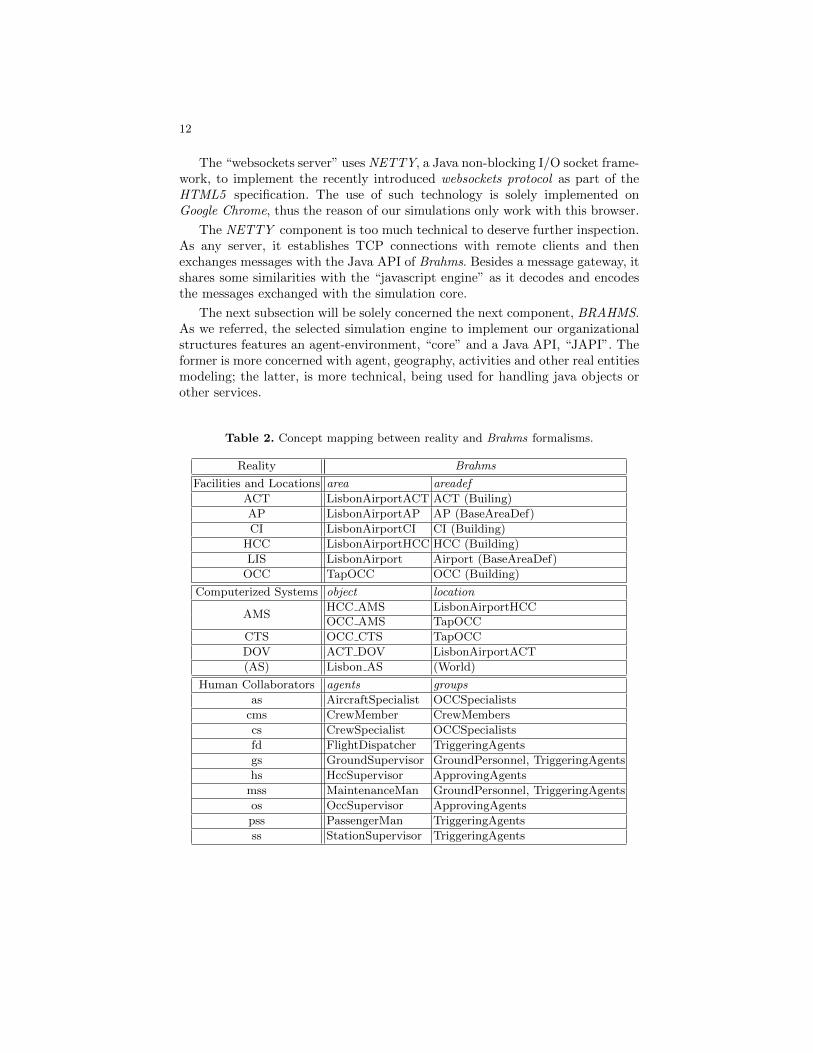
Brahms supplies a number of human-centered structural formalisms to helpmodeling real entities. Thus, one of the first steps in modeling a scenario withBrahms is to make a correspondence between real and artificial concepts. Table 2,intends to clarify our approach concerning such mapping.
Besides presenting a number of associations, table 2 also hopes to illustratethe expressiveness offered by the Brahms modeling language. Although compre-hensive it just contains a subset of Brahms concepts.
The first column respects to the reality, the next two contain the name ofvirtual entities implemented on our simulations. Starting by “Facilities and Lo-cations”, Brahms is very complete in what concerns geography modeling. Thereare areas and areadefs and we may not have the former without the latter, thatis, first the area must be defined, we must specify what it is then we may nameit. Looking at the “ACT” example, we first had to create a generic “ACT” ex-tending the Building definition shipped with Brahms and then we were able todefine “LisbonAirportACT” as an instance of it. In the case of “AP”, AircraftParking, as it is not a Building, we had to choose the BaseAreaDef as parent.
Our naming conventions reveal another Brahms feature not foreseeable inthe table, the part of construct. Listing 1.1 shows an excerpt of the part of andpath formalisms.
Listing 1.1. Excerpt of Brahms area and path definitions
area LisbonAirportAP instanceof AP partof LisbonAirport {
}
path LisAP_to_from_LisHCC {
area1: LisbonAirportAP;
area2: LisbonAirportHCC;
distance: 600;
}
As it is clear, besides specifying what the area is, we may also specify therelation between areas (part of ). Figure 2, shows the Aircraft Parking insidethe Lisbon Airport and Brahms allows such modeling. Another very convenientfeature is the path. It defines a relationship between two areas not in terms ofcomposition but geographical dispersion. Again, something very handy to setthe distances (in seconds) between buildings or areas. The distance, on average,between the Aircraft Parking and the Hub Control Centre is, by feet, 10 minutes,so we must specify it as 600 seconds. As we will see later, if our agents use avehicle, and thus only spend 2 minutes, the 600 seconds time may be overwrittenin the move activity.

14
Moving on to the next portion of table 2, it is about computerized systems.To model inanimate things, Brahms offers the concept of object. Actually, somereal world objects might be modeled as agents because while they are physicallyinanimate, they may be used to reason over facts and therefore help humans takedecision, e.g., a computer. The notion of agent in Brahms is a little narrowerthan other multi-agent systems because objects might also react and reason asagents. Apart from the naming convention used for systems, which is irrelevant,another key property is its location. In Brahms every object and agent might begiven a location. Again, according to figure 2 the airline systems were distributedacross different locations.
Concerning the human collaborators, and as stated above they were modeledas agents. As a multi-agent system, this is no surprise. The innovative factor inBrahms is the existence of groups. When implementing an agent, one may usethe memberof keyword to set its group membership. For instance, In table 2, the“AircraftSpecialist” and the “CrewSpecialist” are members of the same group,the “OCCSpecialists”. This is a very powerful feature in Brahms because whenneed to implement activities to be performed by the agents, we just need to im-plement them at the group level, then the activities are automatically inherited.
Before introducing Brahms activities, we may not skip the “Lisbon AS” ob-ject. The “AS” systems stands for Airport Screen and during our interviews withairline personnel nobody noticed its existence, thus the reason for appearing be-tween parentheses. It is here to illustrate a simple case where a modeler neededto use a workaround to simplify or make it computationally feasible to mimicreality.
Recalling our empirical scenario, when some agents detected anomalies theywould trigger workflows. In table 2 they appear as members of the “TriggeringA-gents” group. In reality, they perceive anomalies in the course of their activities:verifying an aircraft, checking-in passengers, loading cargo, and so on. But in oursimulation we only had files with those anomalies. The closer approach wouldbe to put those agents all reading the file and checking if they were responsibleto trigger the next anomaly. While it would be correct to do that way, it wouldnot be wiser because it would put too much strain on IO operations to read thesame file (or checking the same list), over and over again.
Following this, we created the Airport Screen system that roughly mimicsthose screens found at the airports with the next departures or flight delays.It reads the file and “tells” the agents about upcoming anomalies. Now thathopefully the notion of auxiliary object was explained another topics worthsdiscussion: how does the Airport Screen tell the other agents?
Answering this question definitely proves that Brahms is a fairly differentmulti-agent system founded on a totally new paradigm. As any other program-ming language, the Brahms agent-oriented programming language also supportsthe primitive types, such as integers, characters, etc. and the map collection.Unfortunately, it does not support lists, a major flaw that had to be overcomethrough the use of JAPI, a workaround explained soon. While Brahms supportsthose data types, agents and objects are unable to directly handle them. At this
15
point is very important to underline that Brahms is human-centered and humanbeings do not act or reason upon integers, they do that according facts or beliefs.This is where the BDI software model enters and somehow distinguishes Brahmsfrom the majority of multi-agent systems.
Now that facts and beliefs were introduced, when our Airport Screen detectsan anomaly it creates a fact or belief. As it is located in the “World”, a Brahmsabstraction to everywhere, all the agents or objects perceive such fact/belief. Itis up to the modeler to implement the activities they must perform, if any, whenthey detect the fact.
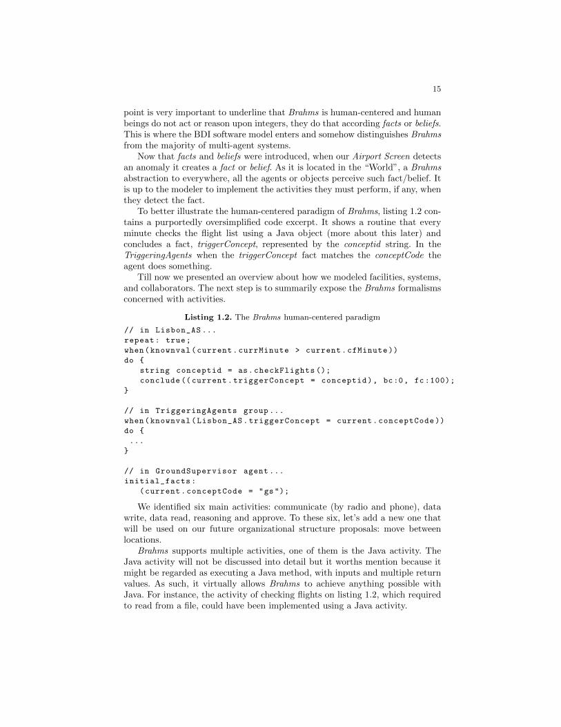
To better illustrate the human-centered paradigm of Brahms, listing 1.2 con-tains a purportedly oversimplified code excerpt. It shows a routine that everyminute checks the flight list using a Java object (more about this later) andconcludes a fact, triggerConcept, represented by the conceptid string. In theTriggeringAgents when the triggerConcept fact matches the conceptCode theagent does something.
Till now we presented an overview about how we modeled facilities, systems,and collaborators. The next step is to summarily expose the Brahms formalismsconcerned with activities.
Listing 1.2. The Brahms human-centered paradigm
// in Lisbon_AS ...
repeat: true;
when(knownval(current.currMinute > current.cfMinute ))
do {
string conceptid = as.checkFlights ();
conclude (( current.triggerConcept = conceptid), bc:0, fc :100);
}
// in TriggeringAgents group ...
when(knownval(Lisbon_AS.triggerConcept = current.conceptCode ))
do {
...
}
// in GroundSupervisor agent ...
initial_facts:
(current.conceptCode = "gs");
We identified six main activities: communicate (by radio and phone), datawrite, data read, reasoning and approve. To these six, let’s add a new one thatwill be used on our future organizational structure proposals: move betweenlocations.
Brahms supports multiple activities, one of them is the Java activity. TheJava activity will not be discussed into detail but it worths mention because itmight be regarded as executing a Java method, with inputs and multiple returnvalues. As such, it virtually allows Brahms to achieve anything possible withJava. For instance, the activity of checking flights on listing 1.2, which requiredto read from a file, could have been implemented using a Java activity.
16
Other types of activities, more relevant to our study were the communicateand the move activities. Concerning the former, what we knew was that certainairline operators, in presence of an anomaly, would pick the radio or phone andcommunicate such fact to a supervisor. We also knew that such activity wouldconsume an indefinite amount of time.
As in other systems, there are always a number of ways to implement thesame scenario and our simulation was no exception. There would be severalways of communicating a disrupted flight but in our case we opted by the flightnumber. Ideally, it would have been better to pass a Java object because, as wewill see soon, our flights were implemented as such. The problem is that agentsin Brahms, as human counterparts, are solely capable of transmitting facts orbeliefs, usually represented through primitive data types.
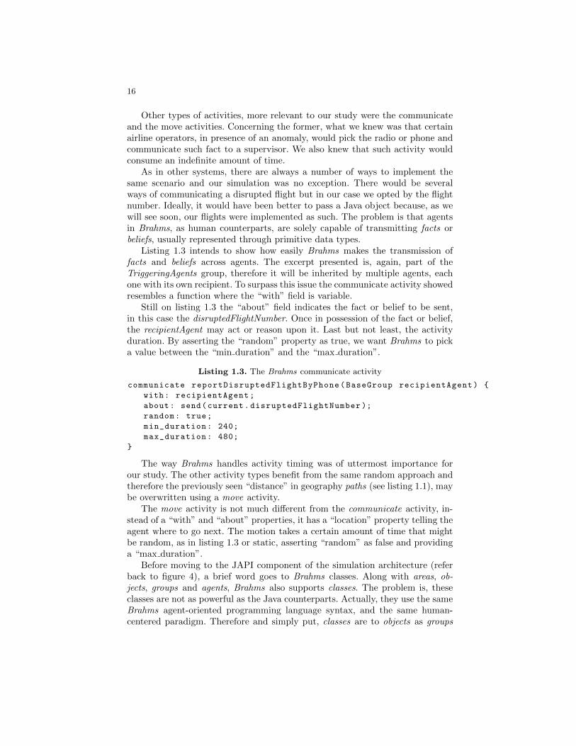
Listing 1.3 intends to show how easily Brahms makes the transmission offacts and beliefs across agents. The excerpt presented is, again, part of theTriggeringAgents group, therefore it will be inherited by multiple agents, eachone with its own recipient. To surpass this issue the communicate activity showedresembles a function where the “with” field is variable.
Still on listing 1.3 the “about” field indicates the fact or belief to be sent,in this case the disruptedFlightNumber. Once in possession of the fact or belief,the recipientAgent may act or reason upon it. Last but not least, the activityduration. By asserting the “random” property as true, we want Brahms to picka value between the “min duration” and the “max duration”.
Listing 1.3. The Brahms communicate activity
communicate reportDisruptedFlightByPhone(BaseGroup recipientAgent) {
with: recipientAgent;
about: send(current.disruptedFlightNumber );
random: true;
min_duration: 240;
max_duration: 480;
}
The way Brahms handles activity timing was of uttermost importance forour study. The other activity types benefit from the same random approach andtherefore the previously seen “distance” in geography paths (see listing 1.1), maybe overwritten using a move activity.
The move activity is not much different from the communicate activity, in-stead of a “with” and “about” properties, it has a “location” property telling theagent where to go next. The motion takes a certain amount of time that mightbe random, as in listing 1.3 or static, asserting “random” as false and providinga “max duration”.
Before moving to the JAPI component of the simulation architecture (referback to figure 4), a brief word goes to Brahms classes. Along with areas, ob-jects, groups and agents, Brahms also supports classes. The problem is, theseclasses are not as powerful as the Java counterparts. Actually, they use the sameBrahms agent-oriented programming language syntax, and the same human-centered paradigm. Therefore and simply put, classes are to objects as groups

17
are to agents. We did not list the classes in table 2 as there is solely one, theTriggeringObjects that works in a similar fashion than TriggeringAgents.
Till now we described our approach in what concerns the modeling of themost visible concepts and activities using the Brahms proprietary agent-orientedlanguage. Although we recognized how expressive, distinct, innovative and some-how powerful it is, we must also underline its shallow learning curve and, as wewill see next, the lack of some widely used data types and support functions.
As we stated previously, Brahms supports several primitive data types andmaps. Unfortunately, lists are not available and they are one of the key datastructures to store our flights. Even the flight object, which is composed ofseveral attributes, such as scheduled departure date or flight number, would bemuch better abstracted by means of plain Java objects.
To address such issues Brahms provides two options. The latest alpha ver-sion allows for direct Java objects manipulation. Older versions support alreadymentioned Java activities. In one case or the other, there are some conventionsone should respect but in the end is roughly like calling a static java method.
Without getting into much detail, in the implementation of our simulations,the Brahms JAPI was used in several scenarios. First and foremost to storewithin ArrayLists our flights and delays objects. Second to perform file inputand output, operations not supported at the Brahms level. Third to implementthe Specialists reasoning activities. Last and fourth to stream the ongoing eventsto the “websockets server”, see figure 4.
To conclude, it worths emphasizing that this section did not aim at thor-oughly describe the implementation of our simulation using Brahms. That wouldrequire a technical manual as long as this report. The intention here was topresent the human-centered nature of Brahms and how that paradigms fit thereality being modeled.
4.3 The Visualization Module
As a side goal, the visualization module was not required to produce the answersto the main goals of this research study. It simply receives some messages fromthe Brahms component, such as which activity is being carried out by whichagent, and displays an animation of the simulated theatre. Therefore, the mainpurpose of the visualization was to provide an educational tool to allow peopleto learn how the airline operations management work and to better understandthe proposed organizational changes.
As it was explained in subsection 4.1, the visualization module uses Pro-cessing.js to render images and animations on the recently introduced HTML5canvas. It is tightly connected to the javascript that decodes the messages com-ing from the simulation.
The visualization is composed by two distinct areas, the operational area,very similar to figure 2 and an airport screen. The former is where the mainaction takes place, through arrows we may observe the current workflow state.The latter provides visual hints about flight departures and state. The airportscreen lists all the flights within a future time frame, if a flight suffers an anomaly

18
it is depicted in a different color and a workflow is triggered in the operationalarea. Assuming it was the Ground Supervisor to detect the anomaly, and its nextactivity is to notify the HCC Supervisor, then an arrow is displayed between himand the HCC Supervisor with a visual indicator of a radio communication.
Without being too much technical, the underlying architecture of the visu-alization had to closely implement the concepts introduced by Brahms. Thismeans we had to implement classes to represent the agents, the objects, the areadefinitions and so on. While requiring an additional effort, such approach alsoallows for a flexible display.
Given the need to represent several distinct organizational structure, thevisualization had to be dependent on the simulation. At the beginning, a listof the Brahms concepts is passed to the visualization so they can be displayed.Other features are also present such as onMouseOver actions that return furtherinformation about the concepts and so on.
To conclude, a final words goes to the amount of Processing code required toimplement solely one action or even Brahms concept. We must keep in mind thatbehind a Brahms concept abstraction there is a complex and large code base,therefore the need to execute the Brahms environment in a virtual machine. Theproblem is that we lack such constructions in Processing and we are requiredto implement them by hand. Following this, to implement every activity orconcept is a lengthly process, the reason why the visualization will always beless expressive than the simulation itself.
5 Scenario and Experiments
This section aims at presenting the underlying aspects of simulation input, trans-formation and output. It provides useful insights to understand the organiza-tional results presented on the next section.
5.1 Simulation Input Data
As advertised, our simulations used real operational data from TAP. In the con-text of our research, a database service was purportedly implemented to collectpre as post flight activity. The pre operational records included the scheduledflights, assigned aircrafts and assigned crew members. On the other hand, postoperational data exposed the flights that actually took off as well as aircraftand crew changes. We were also given a list with all the flights that suffereddeparture delays, the amount of minutes, and the corresponding TAP and IATAdelay codes.
Possessing such data allowed us to input the scheduled flights and treat thedelays, recorded after operation, as anomalies occurred during flight handling,i.e., an actual flight that suffered a delay caused by unexpected late passengercheck-in, would be simulated as suffering a late passenger check-in anomaly.
It worths emphasize the uttermost importance of using real data. In an orga-nizational structure not all the business processes assume the same prevalence,

19
e.g. there are workflows that take place a higher number of times than others.Since we will use anomalies to trigger workflow execution, using random datawould not respect the uneven distribution of processes, compromising the finalresults.
Our simulation was fed with the flights operated by TAP from the 15th tothe 21st February of 2010, a whole seven days week of activity. Although 7317flights were scheduled to take place that week, due to data incompleteness, e.g.missing databases fields, table referential deficiency, inconsistent data, we wereonly able to input 1801 flights, 389 of which suffered anomalies.
5.2 Operational Workflow Transformations
The major goal of our study was to assess distinct airline organizational struc-tures. Based on the actual airline simulation, the control group, three organiza-tional structures were incrementally changed and simulated. All the simulationswere executed after the same operational scenario, comprising the scheduledflights and anomalies referred on the previous subsection. When proposing orga-nizational structure modifications we were cautious not to alter the inputs andoutputs of the business process, i.e. never change the triggering and decidingagents.
Our first proposal (I) suggested the removal of the HCC Supervisor. Afteranalyzing the actual sequence diagrams, we observed that he usually plays asinformation distributor and only assumes a supervising position when facinganomalies related to Passenger Services. Removing the HCC Supervisor requiredthree major changes in four (out of the eight) workflows. The Ground Personnelwas now required to go to the Hub Control Centre to input data into the AMS;OCC Supervisor accumulated the role of notifying Ground Personnel about OCCSpecialists decisions; and the Passenger Services started to report anomalies tothe OCC Supervisor via phone.
Proposal II departed from proposal I and aimed at avoiding the Ground Per-sonnel to go to the Hub Control Centre in order to reach the Aircraft MovementSystem. This way, we suggested to add mobility support to the existing AMS,making it manageable through a wireless smartphone or laptop. Conscious of cer-tain security implications, we decided that at this stage, access would be solelygranted to Ground Personnel. All the remaining operators kept interacting withAMS the same way they did previously.
In our last proposal, III, we removed the usage restrictions on the AMS foundon proposal II and started to think of it as a web-based system accessible fromeverywhere. At this stage, the Flight Dispatcher and the Station Supervisor werenow able to input and read data from the AMS, no matter their location.
5.3 Metrics
Two metrics were used to assess organizational structure performance: overalldisruption handling time and average collaborator stress. While they are both
20
based on the activity duration, they measure different concepts. Overall dis-ruption handling time is the sum of the time consumed by all the workflows,i.e., when an anomaly disrupts a flight it also triggers a workflow composed ofseveral activities, which durations will be summed up until a solution for theanomaly is found. Concerning collaborator stress, it is a metric associated witheach collaborator and thus requires a statistical aggregation to be used, e.g. theaverage. It measures the number of hours spent by a collaborator on the courseof a simulation.
There are activities that contribute only once to the overall disruption han-dling time but several times to the collaborator stress. For instance, a phone callduration is added once to the former, but contributes twice to the overall stress,once per agent involved in the communication.
6 Results and Conclusion
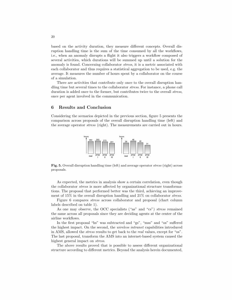
Considering the scenarios depicted in the previous section, figure 5 presents thecomparison across proposals of the overall disruption handling time (left) andthe average operator stress (right). The measurements are carried out in hours.
hours hours
real propI
propII
propIII real prop
IpropII
propIII
283 293 273241 39
4640
31
Fig. 5. Overall disruption handling time (left) and average operator stress (right) acrossproposals.
As expected, the metrics in analysis show a certain correlation, even thoughthe collaborator stress is more affected by organizational structure transforma-tions. The proposal that performed better was the third, achieving an improve-ment of 15% in the overall disruption handling and 21% on collaborator stress.
Figure 6 compares stress across collaborator and proposal (chart columnlabels described on table 1).
As one may observe, the OCC specialists (“as” and “cs”) stress remainedthe same across all proposals since they are deciding agents at the center of theairline workflows.
In the first proposal “hs” was subtracted and “gs”, “mss” and “os” sufferedthe highest impact. On the second, the wireless intranet capabilities introducedin AMS, allowed the stress results to get back to the real values, except for “os”.The last proposal, transform the AMS into an internet-based system caused thehighest general impact on stress.
The above results proved that is possible to assess different organizationalstructure according to different metrics. Beyond the analysis herein documented,

21
99.0869.77
12.17 20.0637.07
8.41
75.85
2.8628.59
as cs fd gs hs mss os pss ss
hours REAL
0.00
99.98
as cs fd gs hs mss os pss ss
hours
71.61
12.2338.57
13.60
103.79
2.9527.53
PROPOSAL I
98.7570.36
12.23 20.620.00 7.01
85.40
2.9727.96
as cs fd gs hs mss os pss ss
hours PROPOSAL II
hours PROPOSAL III100.09
69.44
as cs fd gs hs mss os pss ss9.26
20.590.00 7.68
27.522.84
15.95
Fig. 6. Comparison across collaborator stress and proposal.
the simulation of the real airline organizational structure makes it possible toevaluate other scenarios or introduce new metrics. As an abstract model fromreality, there is always room for simulation evolution.
Finally, it is important to point out that, although we have used a particularairline company for our study and simulation, it is easy to adapt the system toother airline companies as well as to other domains, since the Brahms languageand simulation system are flexible enough for that.
References
1. Calvin H. P. Pava. Managing New Office Technology: An Organizational Strategy.Free Press, New York, 1984.
2. M. Sierhuis and W. Clancey. Modeling and simulating work practice: A method forwork systems design. IEEE Intelligent Systems, 2002.
3. R. Mayer, P. Benjamin, B. Caraway, and M. Painter. Framework and a suite ofmethods for business process reengineering. In V. Grover and W.J. Kettinger, edi-tors, Business Process Change: Reengineering Concepts, Methods and Technologies.Idea Group Publishing, 1998.
4. J. Greenbaum and M. Kyng. Design at Work: Cooperative Design of ComputerSystems. Lawrence Erlbaum Associates, Mahwah, N. J., 1991.
5. W. J. Clancey. Simulating activities: Relating motives, deliberation, and attentivecoordination. Cognitive Systems Review, 2002.

22
6. M. Sierhuis. Modeling and Simulating Work Practice. Brahms: A Multi-agent Mod-eling and Simulation Language for Work System Analysis and Design. PhD thesis,Dept. of Social Science Informatics, Univ. of Amsterdam, Amsterdam, 2001.
7. A. Castro. Centros de controlo operacional: Organizacao e ferramentas. Monographfor Post-graduation in Air Transport Operations, 2008. ISEC - Instituto Superiorde Educacao e Ciencias.
8. Antonio J.M. Castro and Eugenio Oliveira. Disruption management in airline oper-ations control - an intelligent agent-based approach. In Zeeshan ul-hassan UsmaniPhD, editor, Web Intelligence and Intelligent Agents. INTECH, 2010.
9. N. Kohl and S. Karisch. Airline crew rostering: Problem types, modeling, and opti-mization. Annals of Operations Research, 127:223-257, 2004.
10. M. Clarke. Irregular airline operations: A review of the state-of-the-practice inairline operations control centre. Journal of Air Transport Management, 4:67-76,1998.
11. N. Kohl, A. Larsen, J. Larsen, A. Ross, and S. Tiourine. Airline disruption manage-ment: perspectives, experiences and outlook. Journal of Air Transport Management,13:149-62, 2007.
12. G. Yu and X. Qi. Disruption Management: Framework, Models and Applications.World Scientific Publishing Company, 2004.
13. M. Ball, C. Barnhart, G. Nemhauser, and A. Odoni. Air transportation: Irregularoperations and control. In C. Barnhart and G. Laporte, editors, Handbook in OR &MS. Elsevier, Amsterdam, 2007.
14. J. Clausen, A. Larsen, J. Larsen, and N. Rezanova. Disruption management inthe airline industry - Concepts models and methods, Computers & OR, 37:809-821,2010.
15. T. Andersson. Solving the flight perturbation problem with meta heuristics. Jour-nal of Heuristics, 12:37,53, 2006.
16. T. K. Liu, C. R. Jeng, Y. T. Liu, and J. Y. Tzeng. Applications of multi-objectiveevolutionary algorithm to airline disruption management. In IEEE InternationalConference on Systems, Man and Cybernetics. IEEE, New York, 2006.
17. G. Wei, G. Yu, and M. Song. Optimization model and algorithm for crew man-agement during airline irregular operations. Journal of Combinatorial Optimization,1:305,21, 1997.
18. Y. Guo. A decision support framework for the airline crew schedule disruptionmanagement with strategy mapping. In Operations Research Proceedings. Springer-Verlag, Berlin, Heidelberg, 2005.
19. R. Nissen and K. Haase. Duty-period-based network model for crew reschedulingin european airlines. Journal of Scheduling, 9:255,78, 2006.
20. T. Grosche. Computational Intelligence in Integrated Airline Scheduling. Springer-Verlag, Berlin, Heidelberg, 2009.