style 5148 mercurymaster oscillating nozzle … · 2018-10-02 · 122641 style 5148 mercurymaster...
TRANSCRIPT

122641
Style 5148 MERCURYMASTER OSCILLATING NOZZLEOPERATING AND MAINTENANCE INSTRUCTIONS
The following is intended to provide the basic instructions for operating an oscillating MercuryMaster nozzle. Read and understand these operating instructions before use.
PRODUCT RATINGS Maximum Flow: 1000 gpm (3800 lpm)Maximum Pressure: 150 psi (1000 kPa, 10 bar)Mass: 13.1 lbs (5.9 kg) (includes bracket and trunnion)
PRODUCT WARNINGS WARNING: This product is intended for use with the MercuryMaster 1000 portable monitor only. Read and follow
the operating instructions for the style 3446 portable monitor before use. WARNING: Read and follow the operating instructions style 5148 before use. WARNING: Use only for firefighting by trained operators. WARNING: Do not exceed the maximum pressure or flow ratings of the monitor. WARNING: Make sure monitor legs are fully deployed, and all three spikes are in contact with the ground and safety strap is secure before use. WARNING: Make sure the monitor is pointed in a safe direction before flowing water.

WARNING: Make sure the valve is closed when advancing the monitor. Do not move or lift the monitor while flowing. WARNING: The Mercury is supplied with a 3” ball valve. Open and close the valve slowly. Opening and closing the valve too quickly may result in damage to other equipment, which can result in an injury to the operator or others. WARNING: Do not alter any components in any way. WARNING: Charge the unit slowly. Rapid charging may cause a pressure surge with the potential to cause injury or damage
to the unit. WARNING: At pressures below the rated pressure indicated on the label, the nozzle will have reduced flow and reach. Be sure you have enough flow and pressure for the situation (See IFSTA and NFPA manuals for guidelines). WARNING: At pressures below the rated pressure, the oscillating nozzle may not oscillate. Obstructions to the flow through the nozzle will also cause the nozzle to not oscillate. WARNING: Not for use on electrical fires. May cause electrocution. WARNING: Ensure the thread on the nozzle swivel is matched to the thread on the MercuryMaster outlet. WARNING: Read and follow the tip pressure and flows in the operating instructions before use. WARNING: Before operating the oscillating nozzle, make sure that the connecting rod (item 12 in Figure 5) is parallel with the water way. Failure to do so may cause the oscillating mechanism to bind during operation.WARNING: Do not adjust oscillating angle while oscillatingWARNING: Nozzle swivel threads must match Mercury Master outlet threads, do not use thread adapters between monitor and nozzle.
PRODUCT CAUTIONS CAUTION: If any tags or bands on the nozzle are worn or damaged and cannot be easily read, they should be replaced. CAUTION: For use with fresh water or standard fire fighting foams only. Not recommended for use with salt water. After use with foam or salt water, flush with fresh water. CAUTION: Do not over tighten the nozzle onto the mating connection. CAUTION: The nozzle is configured for optimum performance. Do not alter in any manner. CAUTION: Your nozzle should be inspected prior to and after each use, to ensure it is in good operating condition.
Periodically, an unanticipated incident may occur where the nozzle is used in a manner that is inconsistent with standard operating practices and those listed in IFSTA. A partial list of potential misuses follows: • Operating above maximum rated pressure and flow. • Not draining, and allowing water to freeze inside the nozzle. • Dropping the nozzle from a height where damage is incurred. • Prolonged exposure to temperatures above +130 degrees F, or below -25 degrees F. • Operating in a corrosive environment. • Other misuse that might be unique to your specific fire fighting environment.
There are many “tell tale” signs that indicate nozzle repair is in order, such as: • Controls that are either inoperable or difficult to operate. • Excessive wear. • Poor discharge performance. • Water leaks.
If any of the above situations are encountered, the nozzle should be taken out of service and repaired, plus tested by qualified nozzle technicians, prior to placing it back in service.
2

INSTALLATION INSTRUCTIONS
Bracket Installation:1. Elevate the outlet (item 1) to the vertical most position. It is easier to rotate the outlet with a nozzle attached to gain extra leverage. See Figure 12. Using a 5/8” open-end wrench, remove the trunnion (item 2) on the right side of the Mercury Master (standing behind the Mercury inlet and looking from the top view).3. Ensure that the bracket bushing (item 4) is assembled in the bracket (item 5). See Figure 24. Assemble the bracket with bushing onto the brake cap (item 3 in figure 1).5. The trunnion hole in the bracket should align with the trunnion hole on the Mercury Master. Apply Loctite 277 to the threads of the new trunnion (item 6: supplied with the nozzle/ Note: Do not reinsert the trunnion removed in step 2) and assemble the bracket trunnion through the bracket and into the Mercury Master while pushing down on the outlet (item 1) to align the trunnion.6. Tighten the trunnion to 25 ft. - lbs.7. Figure 3 shows a properly installed bracket.
Figure 1
3
Brake Cap (Item 3)
Outlet (Item 1)
Trunnion (Item 2)
TOP VIEW SIDE VIEW

Figure 2
Figure 3
4
Push down to align trunnion.
Bracket Bushing (Item 4) Bracket (Item 5)
Bracket Trunnion (Item 6)
Note: Safety Strap not shown for clarity. DO NOT REMOVE SAFETY STRAP.

Nozzle Installation: WARNING: Ensure the thread on the nozzle swivel is matched to the thread on the MercuryMaster outlet. WARNING: Before operating the oscillating nozzle, make sure that the connecting rod (item 12 in Figure 5) is parallel with the water way. Failure to do so may cause the oscillating mechanism to bind during operation.
1. Begin to tighten nozzle swivel (item 7) to outlet of the Mercury Master. See Figure 42. Before fully tightening the nozzle swivel, rotate the nozzle slightly to assemble rocker shaft pin (item 8) to bracket. Once the rocker pin is assembled, tighten the nozzle swivel snug but not firmly.3. With the oscillation selection in the “OFF” position, rotate the monitor outlet and nozzle horizontally so that the nozzle is pointed straight ahead. The connecting rod (item 12) should be parallel with the waterway. If the connecting rod is not parallel, adjust the oscillating mechanism (item 11) by rotating it about the water way until the connecting rod is parallel. Once the nozzle is level, tighten the swivel firmly making sure to hold the oscillating mechanism to prevent it from moving. See Figure 54. Following the operating instructions, flow water through the nozzle to ensure that the oscillating mechanism does not bind during oscillation.5. The nozzle is ready for use.
5

Figure 4
Figure 5
6
Nozzle Swivel (Item 7)
Rocker Shaft Pin (Item 8)
Oscillation Mechanism (Item 11)
Connecting Rod (Item 12)should be parallel to waterway.

OPERATING INSTRUCTIONS
WARNING: Charge all lines slowly to facilitate a controlled water pressure build-up during start-up. Open and close slowly. Rapid opening will produce a sudden thrust. Rapid opening or closing can cause water hammer. Have enough
firefighters on the line to safely control the reaction force created by the stream. WARNING: Make sure legs are fully deployed, and all three spikes are in contact with the ground and safety strap is secure before use. WARNING: At pressures below the rated pressure, the oscillating nozzle may not oscillate. Obstructions to flow through the nozzle will also cause the nozzle to not oscillate. WARNING: Do not adjust oscillation angle while oscillating.
1. Select the appropriate flow for the application by pushing the baffle in and rotating to the flow setting. See Figure 6
The flow settings are rated at 75 PSI inlet to the nozzle. The following table shows the minimum flow and pressure required to oscillate for the given flow setting. The pressure listed is measured at the MercuryMaster pressure gage.
2. With the oscillation selection set to “off”, adjust the desired angle of oscillation. Push and hold in the unlock button. Hold the arrow indicator wheel (Item 9), while adjusting the angle selection wheel (Item 10) to the desired angle. There are three sets of arrows and angle indicators around the adjustment wheels separated by a solid line. This ensures that an angle setting is always visible as the mechanism turns. See Figure 73. Center the monitor and nozzle on the target. The nozzle will oscillate symmetrically about the center position. The chosen angle is the included angle of travel during oscillation. See Figure 84. With water flowing, move the oscillation selector from “OFF” to “ON” to begin oscillation.
7
Flow Setting Pressure Flow
800 GPM(3000 LPM)
60 PSI(4 bar)
650 GPM(2450 LPM)
1000 GPM(3800 LPM)
30 PSI(2 bar)
650 GPM(2450 LPM)
Minimum Oscillation Requirements
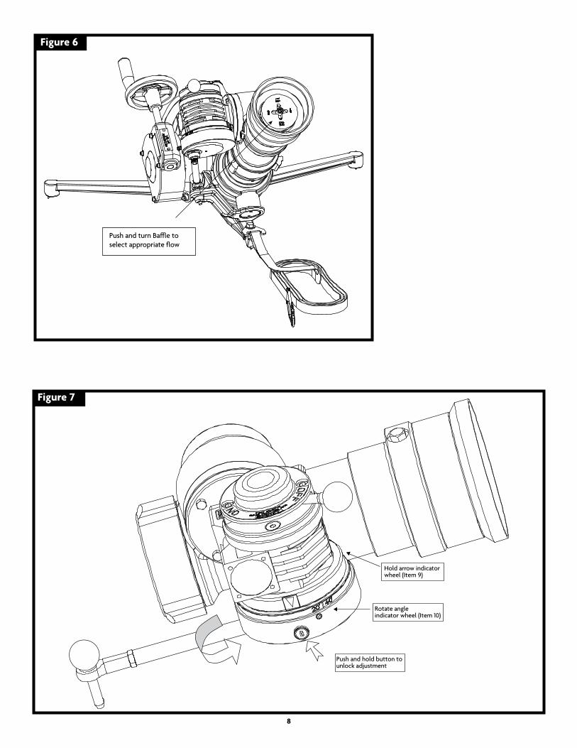
Figure 7
Figure 6
8
Push and turn Ba�e toselect appropriate flow
Hold arrow indicator wheel (Item 9)
Rotate angleindicator wheel (Item 10)
Push and hold button tounlock adjustment

9
Figure 8
Move selectorfrom “OFF” to“ON” to begin oscillation
Selected angle of oscillationbetween 20° and 40°

WARRANTY AND DISCLAIMER: We warrant Akron Brass products for a period of five (5) years after purchase against defects in materials or workmanship. Akron Brass will repair or replace product which fails to satisfy this warranty. Repair or replacement shall be at the discretion of Akron Brass. Products must be promptly returned to Akron Brass for warranty service.
We will not be responsible for: wear and tear; any improper installation, use, maintenance or storage; negligence of the owner or user; repair or modification after delivery; damage; failure to follow our instructions or recommendations; or anything else beyond our control. WE MAKE NO WARRANTIES, EXPRESS OR IMPLIED, OTHER THAN THOSE INCLUDED IN THIS WARRANTY STATEMENT, AND WE DISCLAIM ANY IMPLIED WARRANTY OF MERCHANTABILITY OR FITNESS FOR ANY PARTICULAR PURPOSE. Further, we will not be responsible for any consequential, incidental or indirect damages (including, but not limited to, any loss of profits) from any cause whatsoever. No person has authority to change this warranty.
REvISED: 1/18
ISO 9001 REGISTERED COMPANY
PHONE: 330.264.5678 or 800.228.1161 I FAX: 330.264.2944 or 800.531.7335 I akronbrass.com
© Akron Brass Company. 2011 All rights reserved. No portion of this can be reproduced without the express written consent of Akron Brass Company.
MAINTENANCE • Inspect nozzle prior to and after each use, to ensure it is in good operating condition.• Under normal conditions, periodically flushing the nozzle with clean water, cleaning grit and dirt from around exterior moving parts will allow the nozzle to operate as designed.• Over time the seals may need to be replaced. This can be accomplished by purchasing the appropriate Akron repair kit. Use qualified maintenance mechanics or return the nozzle to Akron Brass for repair. • Regularly check the baffle screw to be sure it is tight. • Use Low-temp Lubriplate on metal parts and Parker O-Ring lubricant on O-Rings