sub: manufacturing process iii code: 10me55 date: 04 / 11
TRANSCRIPT

Page 1 of 2
CMR
INSTITUTE OF
TECHNOLOGY
USN
Internal Assesment Test - II
Sub: Manufacturing Process III Code: 10ME55
Date: 04 / 11 / 2016 Duration: 90 mins Max Marks: 50 Sem: V Branch: MECH
Answer Any FIVE FULL Questions
Marks OBE
CO RBT
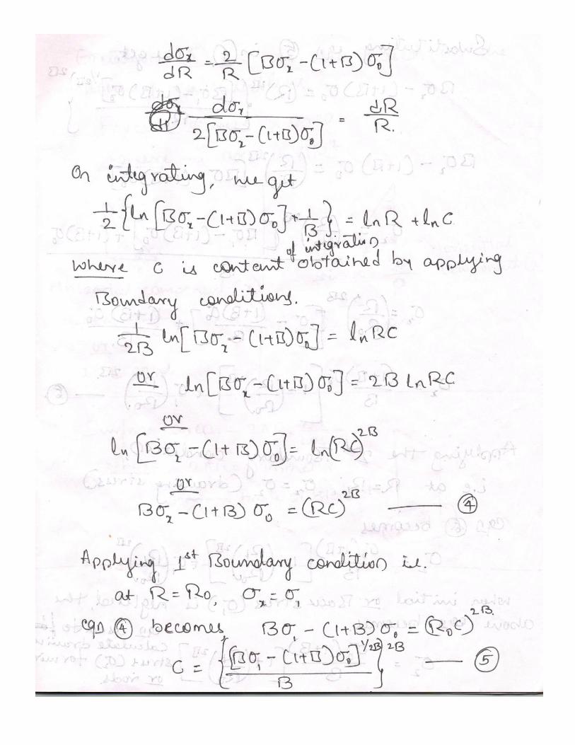
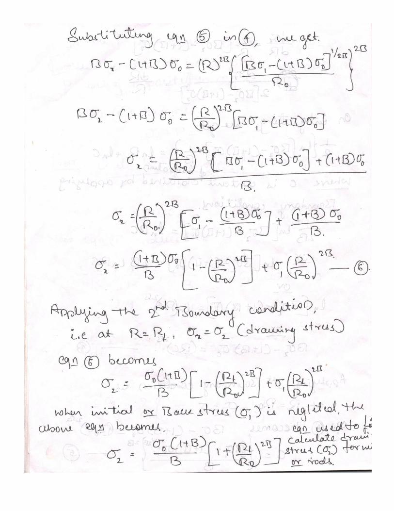
1 Derive an expression for drawing load by slab analysis. [10] CO3 L3
2(a) List and explain a few important process variables that affect the drawing force
in wire drawing process [06]
CO3 L4
(b) Explain tube drawing with floating mandrel [04] CO3 L4
3(a) Calculate the drawing stress to produce 20% reduction in a 10mm stainless
steel wire. The mean flow stress is given by 637 MPa. The die angle is 12o
and the is 0.09. Also determine the power required to draw when the wire is
moving through the die at 3 m/sec.
[06]
CO3 L3
(b) Explain in detail with neat sketch the deformation and lubrication in drawing
process. [04]
CO3 L4
4(a) How seamless pipes are produced in extrusion process? Explain. [06] CO3 L4
(b) Discuss any four extrusion defects with their causes and remedies [04] CO3 L2
5(a) Discuss with a neat sketch extrusion variables. [10] CO3 L2
6(a) In the hot extrusion of aluminum at 350o C, o= 83 MPa.
a) For a 300 mm diameter billet & 1m long, what is the break through
pressure required to extrude a 75 mm diameter bar if =0.10. Take =60o.
b) What is the required extrusion pressure at the end of the stroke?
c) What capacity press would be needed for this extrusion?
[10]
CO3 L4
7(a) With neat sketches, explain combination die and progressive die. [10] CO4 L4

Page 2 of 2
Course Outcomes
PO
1
PO
2
PO
3
PO
4
PO
5
PO
6
PO
7
PO
8
PO
9
PO
10
PO
11
PO
12
CO1:
Apply the concept of plastic deformation
for metals and alloys to convert them in
to useful shapes. Discuss different types
of stresses in metal working and solve
simple numerical on related concepts.
Discuss in detail various parameters in
metal working.
3
CO2:
Classify various metals forming process
like forging Describe various analysis to
determine force and factors affecting it.
solve simple numerical on related
concepts
3 2
CO3:
Illustrate with sketches the
constructional features and describe the
various operations related to the Rolling,
Drawing and Extrusion process.
Describe various analyses to determine
force and factors affecting it. solve
simple numerical on related concepts
3 2
CO4:
Illustrate with sketches the
constructional features and describe the
various operations related to the Sheet
metal forming process. Describe various
analyses to determine force and factors
affecting it. solve simple numerical on
related concepts
3 2
CO5:
Explain the various principles and
applications of High Energy Rate
Forming Methods (HERF). Look into
the concepts related to powder
metallurgy.
3
Cognitive level KEYWORDS
L1 List, define, tell, describe, identify, show, label, collect, examine, tabulate, quote, name, who, when, where, etc.
L2 summarize, describe, interpret, contrast, predict, associate, distinguish, estimate, differentiate, discuss, extend
L3 Apply, demonstrate, calculate, complete, illustrate, show, solve, examine, modify, relate, change, classify,
experiment, discover.
L4 Analyze, separate, order, explain, connect, classify, arrange, divide, compare, select, explain, infer.
L5 Assess, decide, rank, grade, test, measure, recommend, convince, select, judge, explain, discriminate, support,
conclude, compare, summarize.
PO1 - Engineering knowledge; PO2 - Problem analysis; PO3 - Design/development of solutions;
PO4 - Conduct investigations of complex problems; PO5 - Modern tool usage; PO6 - The Engineer and society; PO7-
Environment and sustainability; PO8 – Ethics; PO9 - Individual and team work;
PO10 - Communication; PO11 - Project management and finance; PO12 - Life-long learning

1)
a)


2)
a) Drawing Variable A few important process variables that affect the drawing force in wire drawing process includes:
1) Die angle
2) Temperature
3) Friction/Lubrication
4) Deformation or Reduction in cross sectional area per pass
5) Temperature
6) Drawing speed
Die angle
For small die angle, contact length between wire and the die is more and friction work will be more. With large
die angle redundant work will be increases resulting in the internal distortion of the leading of the work leading
to surface defects in the drawn products. Thus optimum die angel must be selected.
Friction
Friction exists between the work and the die surface, will be more for low die angle, and reduces as the die
angle is increased up to an optimum value.
Temperature
Heat is generated during preliminary by work deformation and sliding friction at the die surface. This cause dies
to expand thermally. To prevent the effects of thermal expansion, it is necessary to flood sufficient lubricants at
the forming sections, or in rare cases, even cool the dies by running a cooling agent through them.
Drawing speed
A faster speed creates more sliding friction; the more the friction, the more is the heat generated and as a result
the amount of strain and stress generated increases. The speed of drawing is hence limited, and is selected
suitably based on the type of material drawn and its diameter.
2)
b) Drawing over a floating mandrel Figure shows drawing with floating mandrel. In this tube drawing process, carefully matched floating mandrel is
used for drawing long tubes. In this process mandrel is not fixed, instead mandrel is pushed in, before drawing takes
place. Because of its conical shape, during the drawing process it is automatically held in position at throat of the die
due to friction between mandrel and tube. It is possible to achieve a reduction in area of 45% and for the same
reduction the drawing loads are lower than for drawing with a fixed mandrel.
Tooling is more critical for this operation than for any of the others. The die land must be long enough to permit
the mandrel to seat in the tube inner diameter, but not so long that friction becomes a problem. In addition to
tool design, lubrication and tube cleanness are critical to successful floating plug drawing. Two chief
advantages of floating plug drawing are that it achieves a higher material yield than any of the other processes
and its long-length capability.

It is the only drawing process for applications that require long lengths with a smooth inner diameter
surface, such as down-hole oil exploration. Thermocouple sheathing that requires a smooth and ultraclean inner
diameter surface is best produced by floating or tethered plug drawing methods.
3)
a)

3)
b) Deformation in Drawing Process The total work required in actual drawing operation are divided into three components are, work required for
homogeneous deformation (Wh), work spent on friction (Wf) and redundant or unwanted (Wr) deformation.
Homogenous work is used to reduce the cross-section, is essentially independent of the die and involves no
losses.
Frictional work spent on overcoming the friction resistance at the work-tool interface.
Redundant work is the work spent in causing internal distortion of the work more than that is actually desired.
Redundant deformation caused by the unwanted internal macro shear in the metal.
In homogenous deformation, plane section remains plane after deformation. While in actual deformation
process, internal macro shear causes distortion of the plane sections. Due to this metal undergoes an excessive
strain than the ideal work. This leads to work hardening and makes the work less ductile.
Redundant work and frictional work have adverse effects on wire properties in addition to increasing the
energy needed for drawing. One consequence is that mechanical properties will not be homogeneous across the
wire cross section. Redundant and frictional deformations are concentrated near the wire surface, higher levels
of strain hardening will result in the surface and near-surface layers (analogous to temper rolling) and will be
greater than the strain that results from cross section reduction. This strain gradient can be verified easily by
performing a hardness survey on a transverse section of cold drawn wire. Also, redundant deformation has an
adverse effect on ductility.
Lubrication Proper lubrication is essential to improve die life, reduce drawing forces and temperature, and improve surface finish
Lubrication is more difficult between the mandrel and workpiece in tube drawing Methods
Wet drawing –dies and rod completely immersed in lubricant (oils or emulsions)

Dry drawing –surface of rod is coated with a lubricant such as soap by passing it through a box filled with
the lubricant (stuffing box)
Coating –the rod or wire is coated with a soft metal (copper or tin) that acts as a solid lubricant
Ultrasonic vibration of the dies and mandrels –reduces friction and allows larger reductions per pass without
failure
4)
a) SEAMLESS PIPE Tubes can also be produced by hollow billet and by using mandrel. The mandrel is fitted at the end of the ram;
hollow sections such as tubes can be extruded to closer tolerances. A mandrel that matches the diameter of the cast
hole in the billet (but slightly smaller than the hole in the die at the opposite end of the chamber) are used. Initially
the mandrel is extends upto the entrance of the die. Clearance between the mandrel and die wall decides the wall
thickness of the tube shown in figure 4.10.a. The mandrel is made to travel along with the ram in order to make
concentric tubes by extrusion. Suitable force is applied to the ram, as the ram moves forward; the metal is forced
over the mandrel and through the hole in the die, causing a long hollow tube.
Tubes can also be made using solid billet and using a piercing mandrel to produce the hollow. The piercing
mandrel is made to move independently with the help of hydraulic press (Refer fig 4.10.b). It moves along with the
ram coaxially. First the ram upsets the billet, keeping the mandrel withdrawn. Next the mandrel first pierced the
solid billet by applying suitable force and mandrel ejects a plug of material from central. Mandrel is extends upto the
entrance of the die (Refer 4.10.c). Clearance between the mandrel and die wall decides the wall thickness of the tube.
As the ram moves forward, the metal is forced over the mandrel and through the hole in the die, causing a long
hollow tube (Refer fig 4.10.d). Just like toothpaste, only hollow.

4)
b) DEFECTS IN EXTRUSION
1) Inhomogeneous deformation in direct extrusion provides the dead zone along the outer surface of the
billet due to the movement of the metal in the centre being higher than the periphery.
After 2/3 of the billet is extruded, the outer surface of the billet (normally with oxidized skin)
moves toward the centre and extrudes to the through the die, resulting in internal oxide stringers.
Transverse section can be seen as an annular ring of oxide.
If lubricant film is carried into the interior of the extrusion along the shear bands, this will show
as longitudinal laminations in a similar way as oxide.
Solutions:
Discard the remainder of the billet (~30%) where the surface oxide begins to enter the die _ not
economical.
Use a follower block with a smaller diameter of the die to scalps the billet and the oxidized layer
remains in the container (in brass extrusion).
2) Surface cracking: it is in the form of rough surface or fir-tree cracking.
Causes:
This is due to longitudinal tensile stresses generated as the extrusion passes through the die. In
hot extrusion, this form of cracking usually is inter-granular and is associated with hot shortness.
The most common case is too high ram speed for the extrusion temperature.
At lower temperature, sticking in the die land and the sudden building up of pressure and then
breakaway will cause transverse cracking.
Solution: use of optimal ram speed and billet interface to obtain a sound product.
3) Laminations of glass/ oxide into the interior of extrusion.
Cause: Improper lubrication method
Remedy: To provide optimum lubrication on the outside of billet and to use optimal ram
speed.
4) Extrusion defect: The last 1/3rd of extrusion may have oxides and other impurities in it rendering it
unfit for use because of poor mechanical properties. This leads to the formation of “annular ring of
oxide” in the extruded product.
Cause: The metal in the middle (2/3rd) is first extruded as it moves faster than the periphery of billet
due to friction. This tendency of extrusion defect increases with friction between billet and container
wall.
Remedy: The last 1/3rd of billet is left out without extruding it. But this is economically not feasible.
Instead a “follower block” is widely used. This block is slightly smaller diameter than the container and
it scalps or scrapes the billet, leaving behind the oxide layers in the container.
5) Axial Hole/ Funnel: It is an axial hole in the back end of extrusion.
Cause: Rapid radial flow of metal during extrusion of last 1/4th of billet.
Remedy: Inclining the face of the ram at an angle to the ram axis.
6) Variations in hot structure and properties within the extrusions due to non-uniform deformation, for
example at the front and the back of the extrusion in both longitudinal and transverse directions.
5)
a) EXTRUSION VARIABLES They affect the extrusion process considerably. They are:
1) Type of extrusion (direct or indirect)
In direct extrusion process, metal begins to flow through the die at the maximum value of the pressure
called “break through pressure”. As billet extrudes, the pressure required progressively decreases with
decreasing length of the billet in the container (because, the friction between the billet and container
decreases).
In indirect extrusion, there is no relative motion between billet and wall. Therefore extrusion
pressure is almost constant with increase in ram travel.

It represents the stress required to deform the metal through the die.
Limited in application by the need of hollow ram, which limits the size of extrusion & pressure.
Hence most of the hot extrusion is done by direct extrusion.
At the end of the ram stroke, there is a rapid pressure build up & therefore a small “ discard ’’ is left
behind in the container, without extruding it.
2. Extrusion Ratio : (R)
R= Initial cross area of the billet / final cross section area after extrusion
R = Ao / Af
Up to = 40: 1 for hot extrusion of steel
Up to = 400: 1 for Aluminium
A small change in the fractional reduction results in large increase in extrusion ratio
Velocity of extruded product = ram velocity x R
Therefore high sliding velocities exist along the die land.
Extrusion Pr. = P = K Ao ln ( Ao / Af )
K = extrusion constant, which accounts for flow stress, friction, and inhomogeneous deformation.
3. Temperature:
Hot extrusion decreases flow stress of metal, but increases oxidation of billet & extrusion tools. Other
features are:
Softens die & tools
Difficult to provide lubrication
Therefore it is advantageous to use the min. temp. which provides required plasticity to metal.
The upper hot working temp. of metal is the temp. at which “ Hot shortness ” occurs.
Higher plastic deformations involved also lead to internal heating of the metal.
Therefore max. working temp. must be safely below the melting point.
Typical Values steel billets heated to 11000 C to 12000 C
Tooling’s: preheated to 350 0 C.
4. Extrusion pressures – range: 800 MPa to 1200 MPa
5. Lubrication: (Glass)
To be maintained at high temperature & under high pressure.
Low strength alloy (Al) does not require lubrication.
Metal deformation is non – uniform and therefore wide variation in heat treatment response is
observed
Effect of temperature, pressure & strain rate on the allowable working range or interdependence of
extrusion speed & temperature:
For a given working pressure & temperature there will be a maximum amount of deformation
possible on the work piece.
As pre heat temperature of billet increases, the flow stress falls & therefore amount of possible
deformation increases
As strain rate of deformation increases, more heat is retained in the work & therefore work
temperature will have to be reduced so that final temperature is below hot shortness temperature.
6. Ram speed:
Increase in ram speed increases the extrusion pressure.
Whereas, low ram speeds leads to cooling of the billet and because of billet cooling, flow stress is
increased.
The higher the temperature of billet, the greater the effect of low extrusion speed on the cooling
of the billet.
Therefore high extrusion speeds are required with high strength alloys which need high extrusion
temperatures.
At the same time at high extrusion speeds, temperature rise due to deformation is greater.

The selection of proper extrusion speed & temperature is best determined by trial & error for
each alloy and billet size.
For a given extrusion pressure the extrusion ratio which can be obtained increases with
increasing temperature.
For a given temperature a large extrusion ratio can be obtained with high pressure.
Maximum billet temperature is determined by the temperature at which melting is about to
occur.
The temperature rise of extrusion is determined by the speed of extrusion & extrusion ratio.
6)
a)

7)
a) Combination dies In this die more than one operation may be performed at one stroke. It differs from compound die in that in this
die, a cutting operation is combined with a bending or drawing operation. Figure explains the working of a
combination blank and draw die. Combination of blanking and drawing die is mounted on the ram and the stock
of sheet metal is kept on the corresponding die set up (fig a). First blanking is done by the blanking die (fig b)
and as the ram advances further, the drawing punch descends and draws the sheet to the required shape (fig c).

Progressive or follow on dies
This dies have a series of stations. At each station, an operation is performed on a workpiece during a stroke of
the press. Between the strokes, the piece in the metal sheet is transferred to the next station. A finished
workpiece is made at each stroke of the press. First piercing is done and sheet metal is moved under the
blanking punch and blanking can be performed to finish the job. Thus after the first stroke when only a hole will
be punched, each stroke of press produces a finished washer as a result rate of production increases.