sub-mm linear ion trap mass spectrometer made using ... · lithographically-defined metal...
TRANSCRIPT

Sub-mm Linear Ion Trap Mass Spectrometer
Made Using Lithographically Patterned
Ceramic Plates
Ailin Li
Brigham Young University, Provo, UT
Coauthors: Qinghao Wu, Yuan Tian, Derek Andrews, Aaron Hawkins, and
Daniel E. Austin

Towards the Portable Mass Spectrometer
Good performance
Rugged
Goes anywhere
Fast Results
Low cost
High
performance
Fragile
Cannot be moved
No hurry
High cost

Mass Analyzer Miniaturization Leads to Smaller Overall Instrument
Smaller vacuum pumps
Smaller batteries
Smaller
detector
Smaller vacuum
chamber
Smaller Mass Analyzer
Smaller
electronicsSm
alle
r mean fre
e p
ath
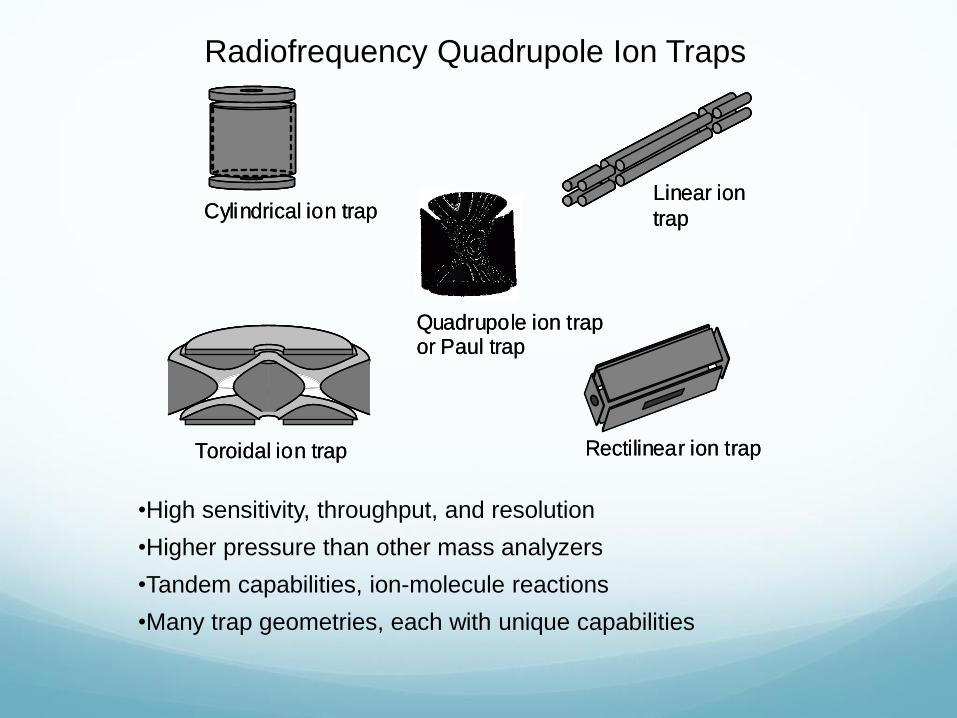
Radiofrequency Quadrupole Ion Traps
•High sensitivity, throughput, and resolution
•Higher pressure than other mass analyzers
•Tandem capabilities, ion-molecule reactions
•Many trap geometries, each with unique capabilities
Linear ion
trap
Rectilinear ion trap
Toroidal ion trap Cylindrical ion trap
Quadrupole ion trap or Paul trap
Quadrupole
mass filter
Linear ion
trap
Rectilinear ion trap
Toroidal ion trap Cylindrical ion trap
Quadrupole ion trap or Paul trap
Quadrupole
mass filter
Linear ion
trap
Rectilinear ion trap
Toroidal ion trap Cylindrical ion trap
Quadrupole ion trap or Paul trap
Quadrupole
mass filter
Linear ion
trap
Rectilinear ion trap
Toroidal ion trap Cylindrical ion trap
Quadrupole ion trap or Paul trap
Quadrupole
mass filter
Linear ion
trap
Rectilinear ion trap
Toroidal ion trap Cylindrical ion trap
Quadrupole ion trap or Paul trap
Quadrupole
mass filter
Linear ion
trap
Rectilinear ion trap
Toroidal ion trap Cylindrical ion trap
Quadrupole ion trap or Paul trap
Quadrupole
mass filter
Linear ion
trap
Rectilinear ion trap
Toroidal ion trap Cylindrical ion trap
Quadrupole ion trap or Paul trap
Quadrupole
mass filter
Linear ion
trap
Rectilinear ion trap
Toroidal ion trap Cylindrical ion trap
Quadrupole ion trap or Paul trap
Quadrupole
mass filter
Linear ion
trap
Rectilinear ion trap
Toroidal ion trap Cylindrical ion trap
Quadrupole ion trap or Paul trap
Quadrupole
mass filter
Linear ion
trap
Rectilinear ion trap
Toroidal ion trap Cylindrical ion trap
Quadrupole ion trap or Paul trap
Quadrupole
mass filter
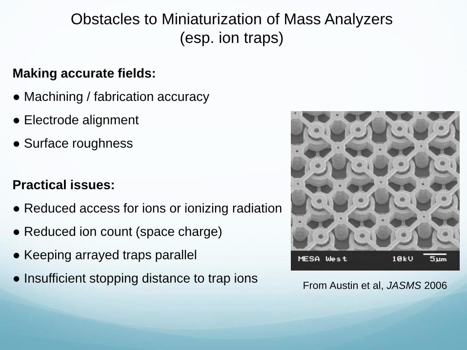
Obstacles to Miniaturization of Mass Analyzers
(esp. ion traps)
Making accurate fields:
● Machining / fabrication accuracy
● Electrode alignment
● Surface roughness
Practical issues:
● Reduced access for ions or ionizing radiation
● Reduced ion count (space charge)
● Keeping arrayed traps parallel
● Insufficient stopping distance to trap ionsFrom Austin et al, JASMS 2006

Two-Plate Ion Traps
Each plate contains series of
lithographically-defined metal “wires”,
overlaid with resistive germanium
Different RF amplitudes applied to
each “wire” produce trapping fields
Aluminum rings
Capacitors
Ceramic plate
Aluminum contact pads
Germanium
Gold vias
50-100 nm germanium layer
prevents charge build-up
and provides continuous
surface potential
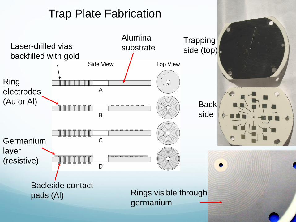
Trap Plate Fabrication
Backside contact
pads (Al)
Laser-drilled vias
backfilled with gold
Alumina
substrate
Ring
electrodes
(Au or Al)
Germanium
layer
(resistive)
Rings visible through
germanium
Trapping
side (top)
Back
side
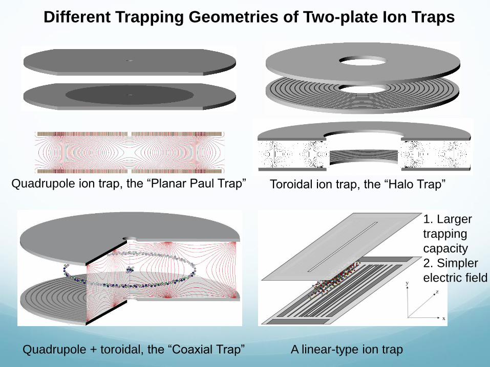
Different Trapping Geometries of Two-plate Ion Traps
Toroidal ion trap, the “Halo Trap”Quadrupole ion trap, the “Planar Paul Trap”
Quadrupole + toroidal, the “Coaxial Trap” A linear-type ion trap
1. Larger
trapping
capacity
2. Simpler
electric field

Two-plate Linear Ion Trap
Back side Trapping side
DC trapping potential
Mounting holes
Ejection slit
Patterned electrodes
DC trapping potential
Original design: r0 = 2.19 mm
Mass spectra with r0 < 1 mm were also demonstrated
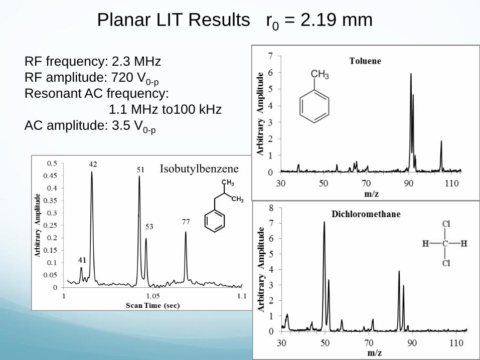
Isobutylbenzene
RF frequency: 2.3 MHz
RF amplitude: 720 V0-p
Resonant AC frequency:
1.1 MHz to100 kHz
AC amplitude: 3.5 V0-p
Planar LIT Results r0 = 2.19 mm
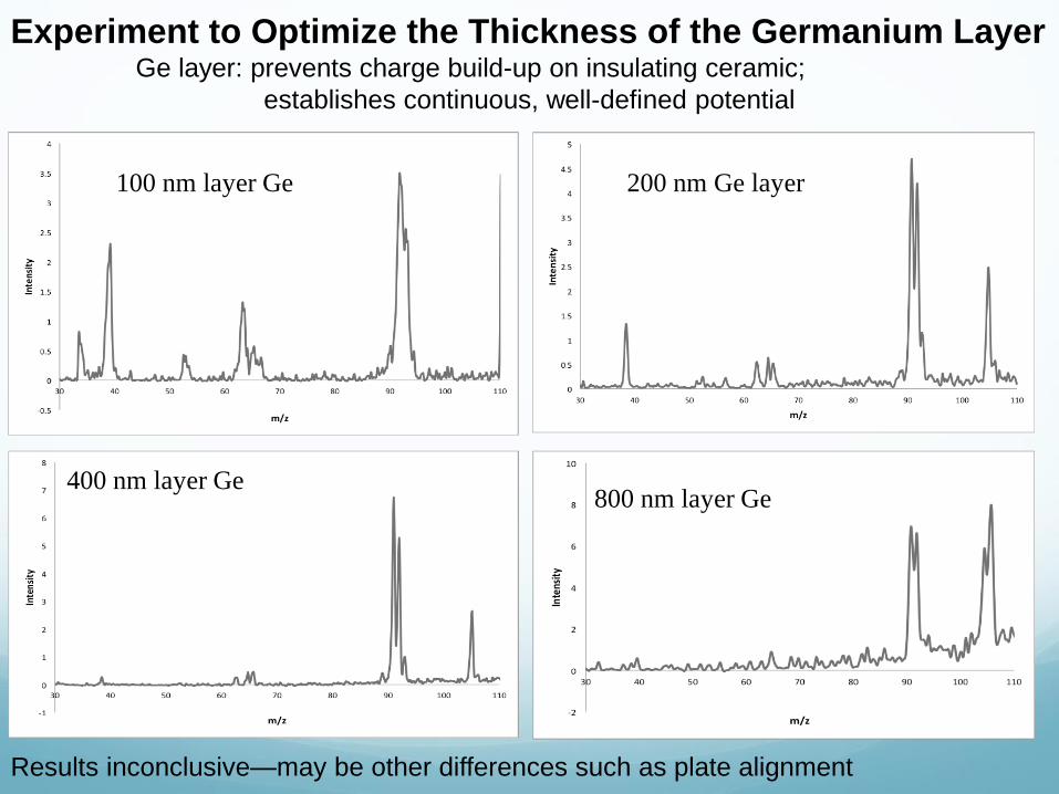
100 nm layer Ge 200 nm Ge layer
400 nm layer Ge800 nm layer Ge
Experiment to Optimize the Thickness of the Germanium LayerGe layer: prevents charge build-up on insulating ceramic;
establishes continuous, well-defined potential
Results inconclusive—may be other differences such as plate alignment
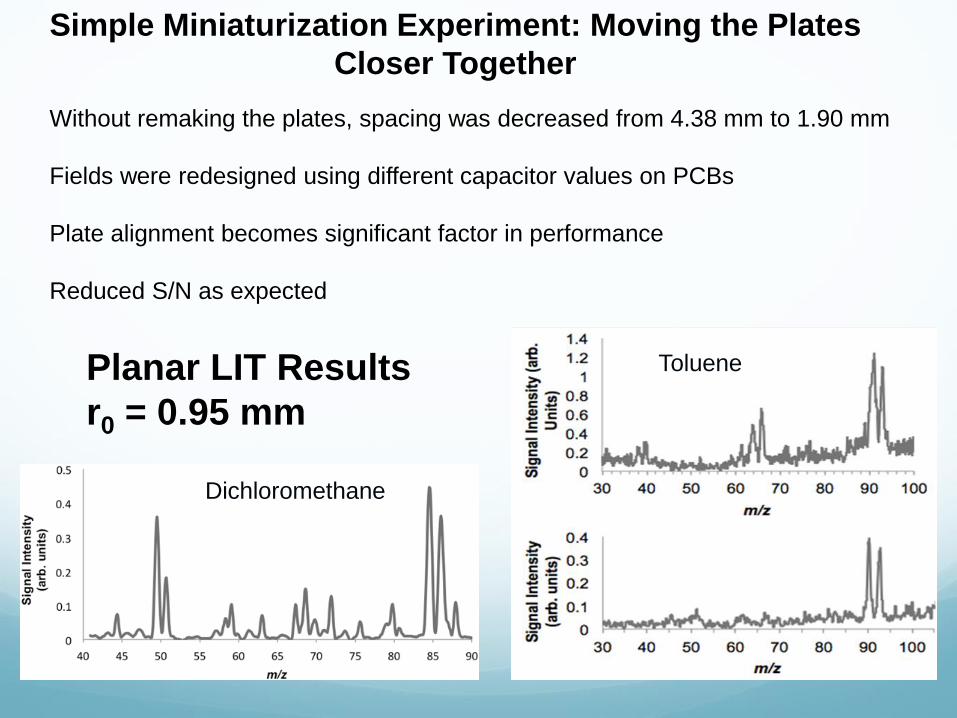
Simple Miniaturization Experiment: Moving the Plates
Closer Together
Without remaking the plates, spacing was decreased from 4.38 mm to 1.90 mm
Fields were redesigned using different capacitor values on PCBs
Plate alignment becomes significant factor in performance
Reduced S/N as expected
Dichloromethane
ToluenePlanar LIT Results
r0 = 0.95 mm
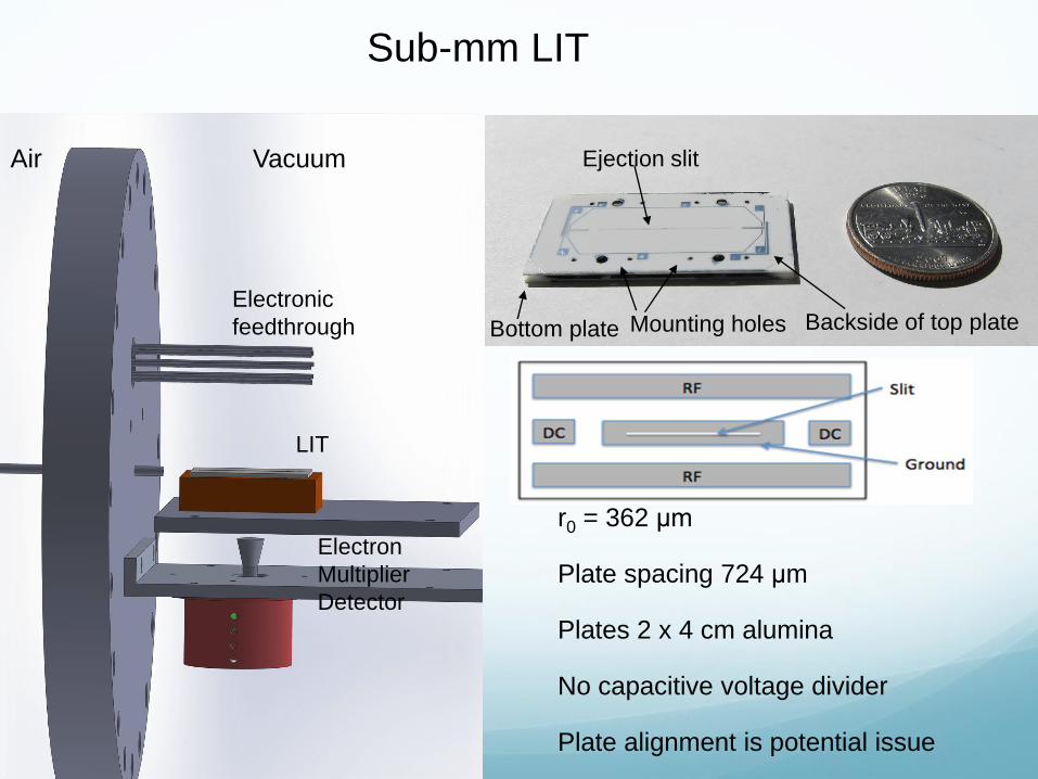
r0 = 362 μm
Plate spacing 724 μm
Plates 2 x 4 cm alumina
No capacitive voltage divider
Plate alignment is potential issue
Sub-mm LIT
Ejection slit
Bottom plate Mounting holes Backside of top plateElectronic
feedthrough
LIT
Electron
Multiplier
Detector
Air Vacuum

Sub-mm LIT
Ion Trapping Capacity
Cylindrical Ion TrapSub-mm LIT
85000 29000
r0 = 362 μm
Linear ion trap Cylindrical ion trap
V0-p
Capacity
Ω 4 MHz 3.8 MHz
190 V50 V

L. Ding, S. Kumashiro. Ion motion in the rectangular wave quadrupole field
and digital operation mode of a quadrupole ion trap mass spectrometer.
Rapid Commun. Mass Spectrom. 2006, 20, 3.
New Method with New LIT
–– Digital Operation
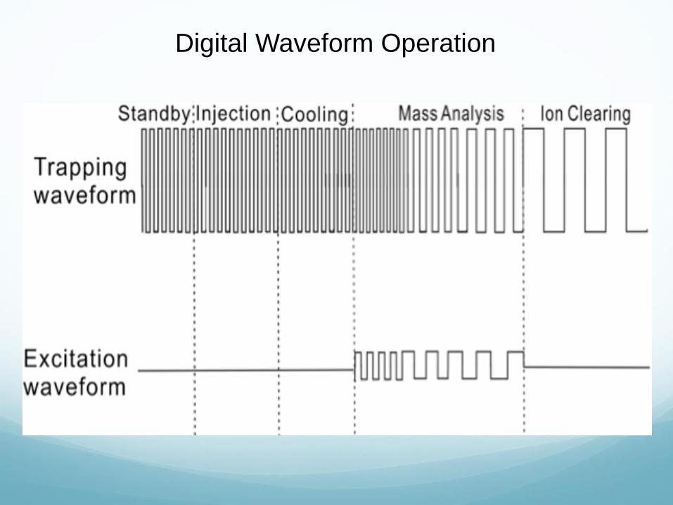
Digital Waveform Operation
Advantages
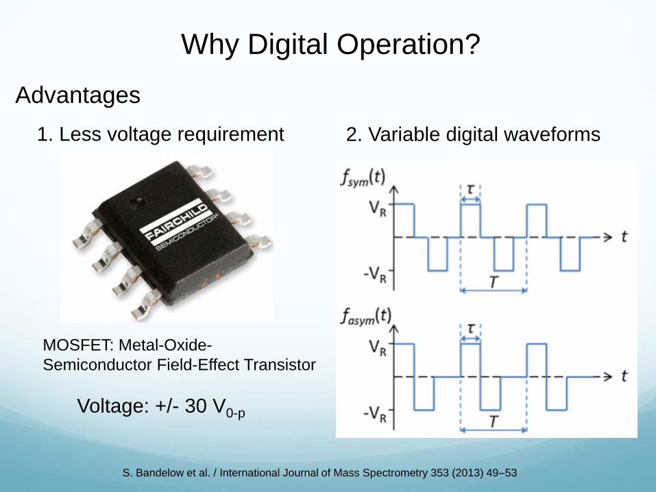
Why Digital Operation?
1. Less voltage requirement 2. Variable digital waveforms
Voltage: +/- 30 V0-p
MOSFET: Metal-Oxide-
Semiconductor Field-Effect Transistor
S. Bandelow et al. / International Journal of Mass Spectrometry 353 (2013) 49–53

Vacuum Chamber
Ion Trap
Interface
(Combines all
inputs into one
output cable)
Agilent Triple Output
DC Power Supply DC end bar V
SRS Function
Generator
Trapping waveform
+V power supply
SRS Function
Generator
Trapping Waveform
BNC
Pulse/Delay
Generator
(Timing)
Detector power
supplyDetector negative V
Detector Output signal
Excitation Waveform
LeCroy
OscilloscopeTrapping Waveform
Ion trap inputs
Pre-
amplifier
Trapping Waveform
Trapping waveform
-V power supply
MOSFET
Excitation Waveform
Trapping Waveform
Amplitude shape for
Trapping Waveform
Excitation Waveform
KEY:
Instrument
Function
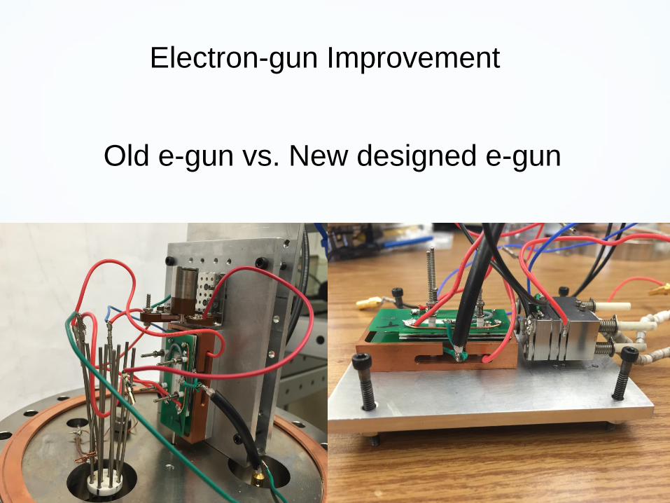
Old e-gun vs. New designed e-gun
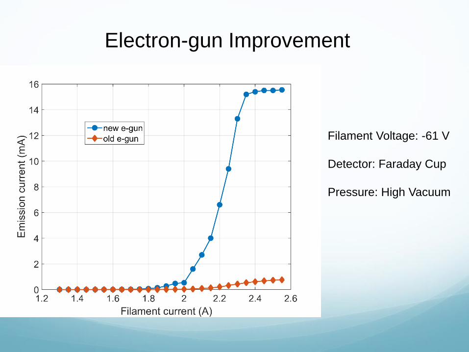
Electron-gun Improvement
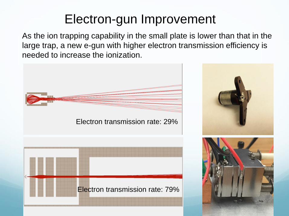
As the ion trapping capability in the small plate is lower than that in the
large trap, a new e-gun with higher electron transmission efficiency is
needed to increase the ionization.
Electron transmission rate: 79%
Electron transmission rate: 29%
Electron-gun Improvement
Electron-gun Improvement
Filament Voltage: -61 V
Detector: Faraday Cup
Pressure: High Vacuum

Improvements in
detectors, vacuum,
electronics, batteries
Converging onto a Truly Portable Mass Spectrometer
New fabrication
techniques: smaller,
more precision
Novel ion traps,
extended trapping
dimensions, arrays
New
ionization
techniquesTandem MS
Sampling
selectivity

Dr.
Qinghao
Wu
Funding from NASA, NSF and DoD
Thanks also to:
Dr. Steve Lammert (Perkin Elmer Corp.)
Acknowledgments
Yuan Tian
Ailin Li Dr. Daniel
Austin
Dr. Aaron
Hawkins
Derek
Andrews


Gas breakdown? Or not?
High vacuum
Very low density
High mean free path
Less collision ionization
High breakdown
voltage
Paschen’s Law: V= f (dp)
Next generation design LIT:
Pressure * Gap ≈ 2.8E-7
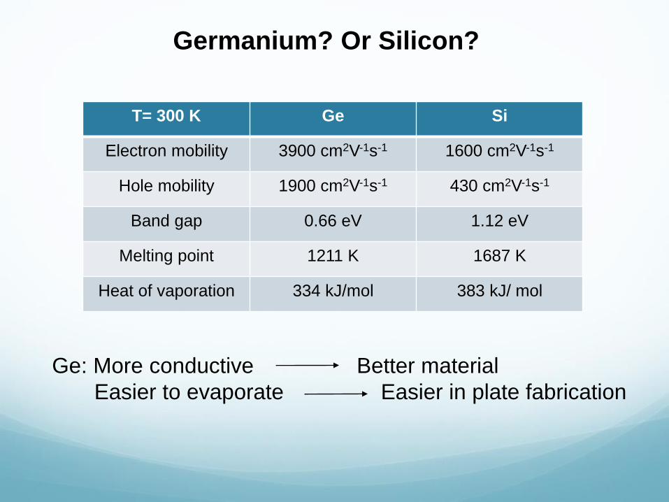
Germanium? Or Silicon?
T= 300 K Ge Si
Electron mobility 3900 cm2V-1s-1 1600 cm2V-1s-1
Hole mobility 1900 cm2V-1s-1 430 cm2V-1s-1
Band gap 0.66 eV 1.12 eV
Melting point 1211 K 1687 K
Heat of vaporation 334 kJ/mol 383 kJ/ mol
Ge: More conductive Better material
Easier to evaporate Easier in plate fabrication

Electric Field Simulated by SIMION
Next generation LIT
r0=360 μm
RIT
x0= 5 mm, y0= 4 mm
150 configurations were simulated to find a similar
electric field with the published optimal electric field of RIT.
