subcooled condensers - edge solution india
TRANSCRIPT
Steriflow by Jordan Valve 3170 Wasson Road • Cincinnati, OH 45209 513.533.5600 • 800.543.7311 • 513.871.0105 (f)[email protected] • www.steriflowvalve.com
SSC SeriesSubcooled Condensers
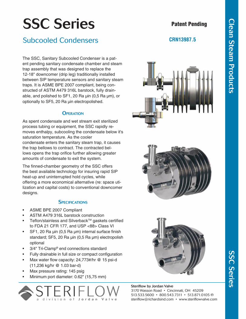
The SSC, Sanitary Subcooled Condenser is a pat-ent pending sanitary condensate chamber and steam trap assembly that was designed to replace the 12-18" downcomer (drip leg) traditionally installed between SIP temperature sensors and sanitary steam traps. It is ASME BPE 2007 compliant, being con-structed of ASTM A479 316L barstock, fully drain-able, and polished to SF1, 20 Ra µin (0,5 Ra µm), or optionally to SF5, 20 Ra µin electropolished.
OperatiOn
As spent condensate and wet stream exit sterilized process tubing or equipment, the SSC rapidly re-moves enthalpy, subcooling the condensate below it's saturation temperature. As the cooler condensate enters the sanitary steam trap, it causes the trap bellows to contract. The contracted bel-lows opens the trap orifice further allowing greater amounts of condensate to exit the system.
The finned-chamber geometry of the SSC offers the best available technology for insuring rapid SIP heat-up and uninterrupted hold cycles, while offering a more economical alternative (re: space uti-lization and capital costs) to conventional downcomer designs.
SpecificatiOnS
• ASME BPE 2007 Compliant• ASTM A479 316L barstock construction• Teflon/stainless and SilverbackTM gaskets certified
to FDA 21 CFR 177, and USP <88> Class VI• SF1, 20 Ra µin (0,5 Ra µm) internal surface finish
standard; SF5, 20 Ra µin (0,5 Ra µm) electropolish optional
• 3/4" Tri-Clamp® end connections standard• Fully drainable in full size or compact configuration• Max water flow capacity: 24,773#/hr @ 15 psi-d
(11,236 kg/hr @ 1.03 bar-d)• Max pressure rating: 145 psig• Minimum port diameter: 0.62" (15,75 mm)
Cle
an Ste
am Pro
ducts
SS
C S
erie
sPatent Pending
CRN13987.5
SSC SerieS
Project CAPex savings on new, or retrofit installations• The SSC can significantly reduce Project CAPex by reducing SIP temperature sensor/trap assembly TIC
(total installed cost), by reducing the cost for OEM process skids, or for retrofit and new site built installa-tions. The savings accrue from the SSC's smaller installed space envelope relative to traditional site built SIP downcomer assemblies, and from the installation labor, materials handling and purchasing expense reduction associated with the purchase of a prefabricated SSC SIP Assembly.
TIC (Total Installed Cost) reductions — Significant reductions in Installation Labor and Material Handling costs: Everything comes preassembled sealed in tagged plastic bags: no on site material consolidation, staging, tube bending, assembly, welding, polishing, or work inspection labor costs
— One purchase order for Tubing, Fittings, Valves, Temperature Sensor, and Steam Trap
Process skid capital cost reduction: — Use of the SSC will result in up to 15" skid height reduction – lower overall process skid material and labor costs
Process retrofit capital cost reduction: — SSC allows use of SIP steam trap/sensor in vertically constrained spaces (under vessels) without altering vessel height or requiring thru-the-floor downcomers
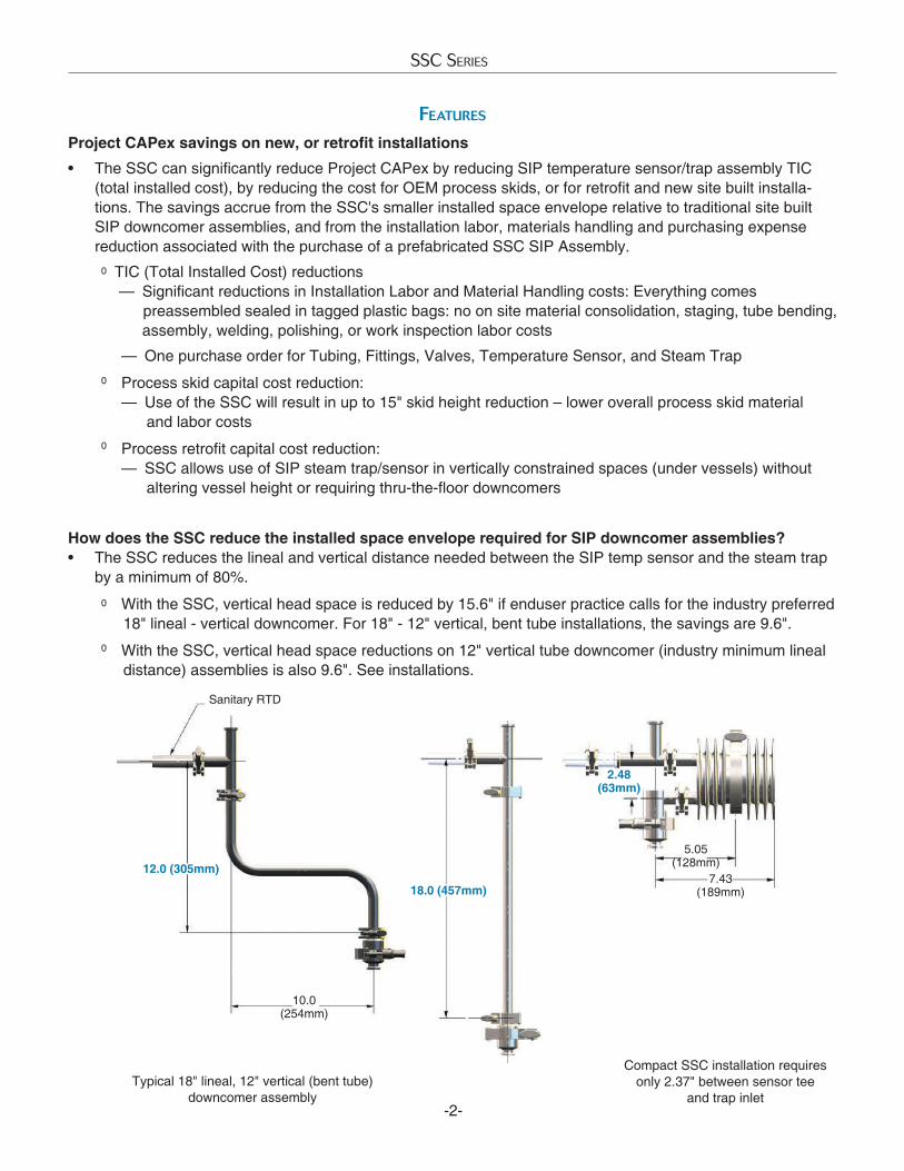
How does the SSC reduce the installed space envelope required for SIP downcomer assemblies?• The SSC reduces the lineal and vertical distance needed between the SIP temp sensor and the steam trap
by a minimum of 80%. With the SSC, vertical head space is reduced by 15.6" if enduser practice calls for the industry preferred 18" lineal - vertical downcomer. For 18" - 12" vertical, bent tube installations, the savings are 9.6".
With the SSC, vertical head space reductions on 12" vertical tube downcomer (industry minimum lineal distance) assemblies is also 9.6". See installations.
-2-
featureS
o
o
o
o
o
12.0 (305mm)
10.0 (254mm)
Sanitary RTD
18.0 (457mm)7.43
(189mm)
5.05 (128mm)
Compact SSC installation requires only 2.37" between sensor tee
and trap inletTypical 18" lineal, 12" vertical (bent tube)
downcomer assembly
2.48 (63mm)
SSC SerieS
-3-
Increased Process Availability• The SSC increases process equipment availability by reducing average annual SIP time. The device
dramatically reduces the probability of SIP wetted temperature sensor faults, and total heat-up time. The SSC design makes it impossible for spent condensate to touch (cool) the SIP temperature sensor upstream of the trap under expected load conditions. And, it ensures that condensate cannot cool (and insulate) critical process areas that are being sterilized during heat-up or temperature hold periods.
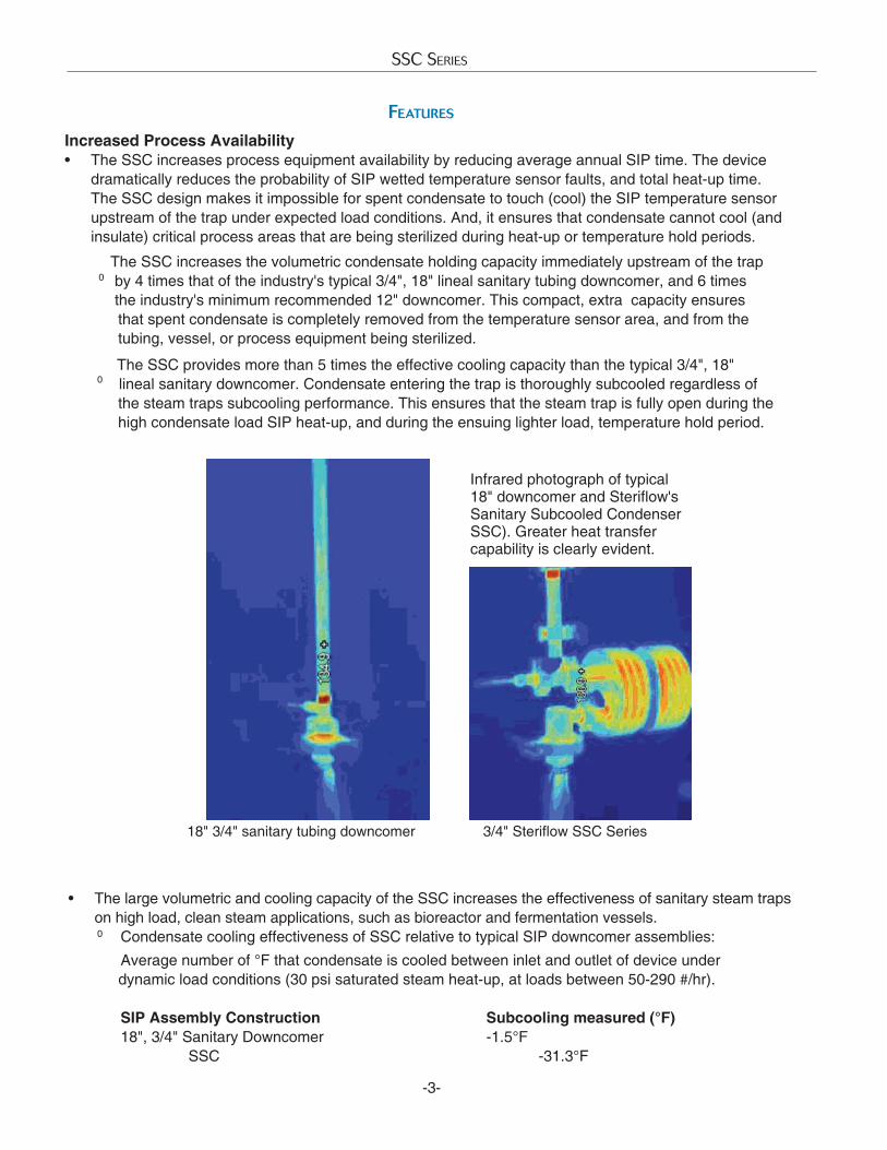
The SSC increases the volumetric condensate holding capacity immediately upstream of the trap by 4 times that of the industry's typical 3/4", 18" lineal sanitary tubing downcomer, and 6 times the industry's minimum recommended 12" downcomer. This compact, extra capacity ensures that spent condensate is completely removed from the temperature sensor area, and from the tubing, vessel, or process equipment being sterilized. The SSC provides more than 5 times the effective cooling capacity than the typical 3/4", 18" lineal sanitary downcomer. Condensate entering the trap is thoroughly subcooled regardless of the steam traps subcooling performance. This ensures that the steam trap is fully open during the high condensate load SIP heat-up, and during the ensuing lighter load, temperature hold period.
featureS
Infrared photograph of typical 18" downcomer and Steriflow's Sanitary Subcooled Condenser SSC). Greater heat transfer capability is clearly evident.
18" 3/4" sanitary tubing downcomer 3/4" Steriflow SSC Series
• The large volumetric and cooling capacity of the SSC increases the effectiveness of sanitary steam traps on high load, clean steam applications, such as bioreactor and fermentation vessels.
Condensate cooling effectiveness of SSC relative to typical SIP downcomer assemblies: Average number of °F that condensate is cooled between inlet and outlet of device under dynamic load conditions (30 psi saturated steam heat-up, at loads between 50-290 #/hr). SIP Assembly Construction Subcooling measured (°F) 18", 3/4" Sanitary Downcomer -1.5°F SSC -31.3°F
o
o
o
-4-
SSC SerieS
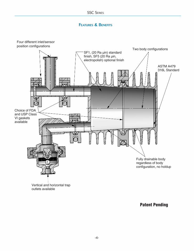
Four different inlet/sensor position configurations
SF1, (20 Ra µin) standard finish, SF5 (20 Ra µin, electropolish) optional finish
Two body configurations
ASTM A479 316L Standard
Fully drainable body regardless of body configuration, no holdup
Vertical and horizontal trap outlets available
Choice of FDA and USP Class VI gaskets available
Patent Pending
featureS & BenefitS
-5-
SSC SerieS
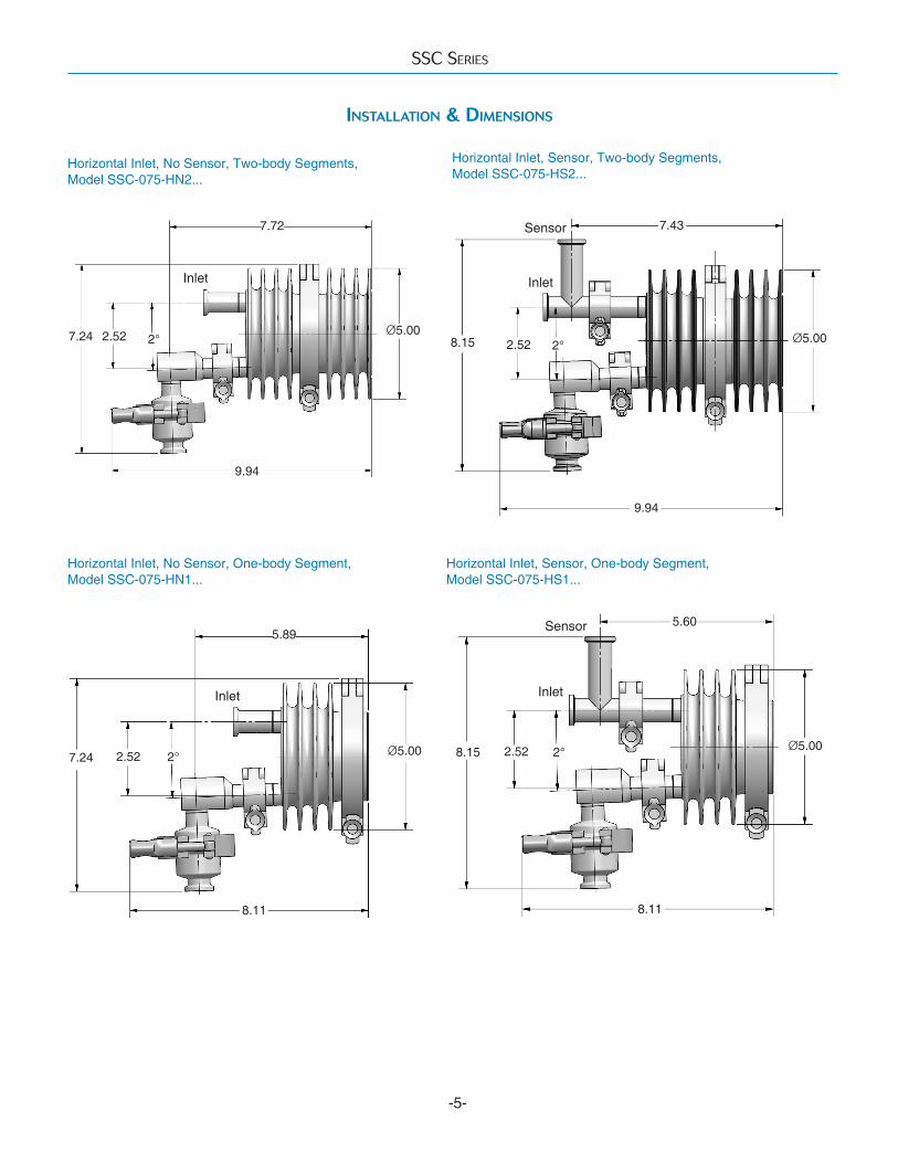
Horizontal Inlet, No Sensor, Two-body Segments, Model SSC-075-HN2...
Horizontal Inlet, Sensor, Two-body Segments, Model SSC-075-HS2...
Horizontal Inlet, No Sensor, One-body Segment, Model SSC-075-HN1...
Horizontal Inlet, Sensor, One-body Segment, Model SSC-075-HS1...
inStallatiOn & DimenSiOnS
Inlet
Inlet Inlet
Inlet
Sensor
Sensor
7.72
Ø5.002°2.52
9.94
Ø5.00
9.94
8.15 2.52
7.43
2.527.24
8.11
5.89
Ø5.00 Ø5.00
8.11
2.528.15
5.60
7.242°
2° 2°
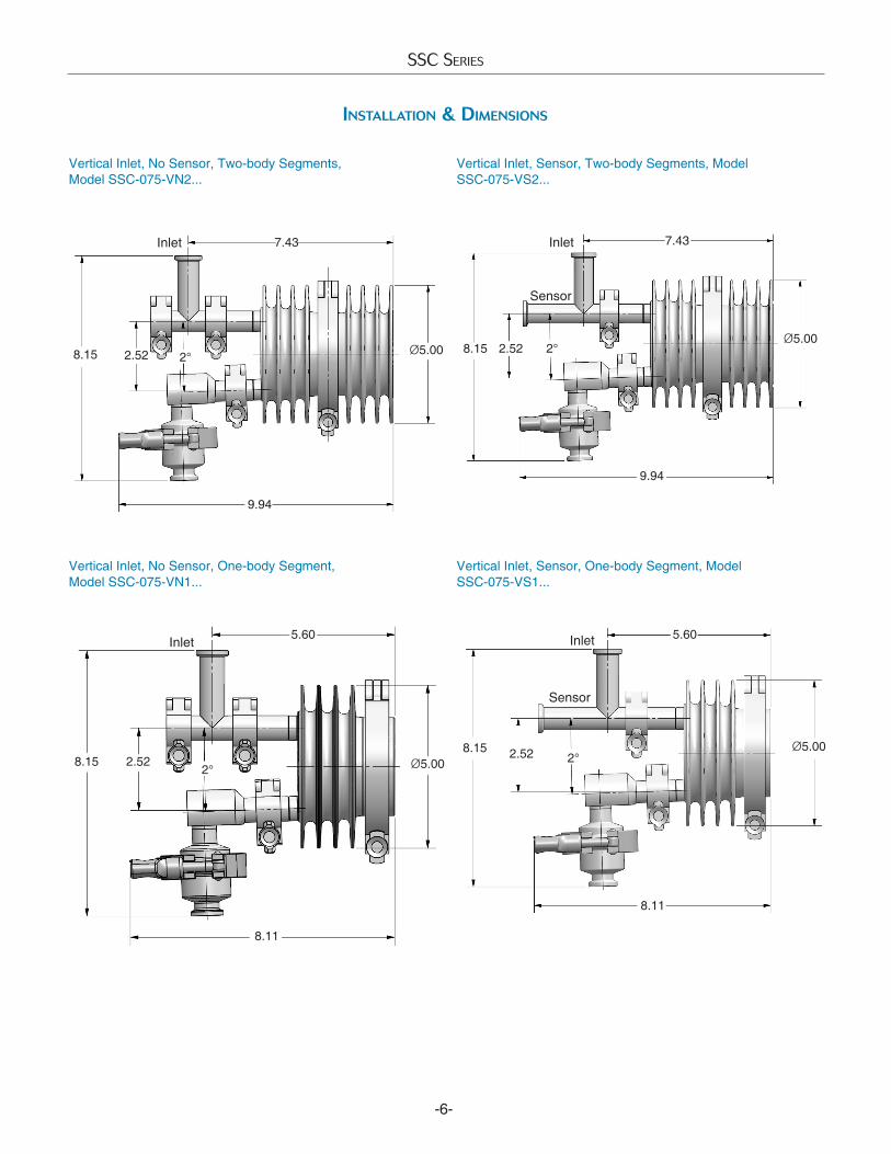
Vertical Inlet, No Sensor, Two-body Segments, Model SSC-075-VN2...
Vertical Inlet, Sensor, Two-body Segments, Model SSC-075-VS2...
Vertical Inlet, No Sensor, One-body Segment, Model SSC-075-VN1...
Vertical Inlet, Sensor, One-body Segment, Model SSC-075-VS1...
Inlet
-6-
SSC SerieS
inStallatiOn & DimenSiOnS
Inlet Inlet
Inlet
Sensor
Sensor
8.15
9.94
2.52
7.43
Ø5.00
9.94
Ø5.00
7.43
2.52
8.11
Ø5.002.528.15Ø5.008.15 2.52
5.60
8.11
2°8.15 2°
2°
5.60
2°
SSC SerieS
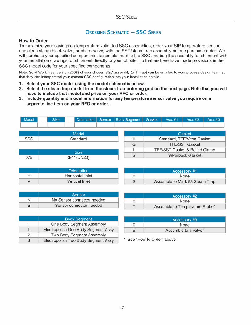
OrDering Schematic — SSc SerieS
ModelSSC Standard
How to OrderTo maximize your savings on temperature validated SSC assemblies, order your SIP temperature sensor and clean steam block valve, or check valve, with the SSC/steam trap assembly on one purchase order. We will purchase your specified components, assemble them to the SSC and bag the assembly for shipment with your installation drawings for shipment directly to your job site. To that end, we have made provisions in the SSC model code for your specified components. Note: Solid Work files (version 2008) of your chosen SSC assembly (with trap) can be emailed to your process design team so that they can incorporated your chosen SSC configuration into your installation details.
1. Select your SSC model using the model schematic below. 2. Select the steam trap model from the steam trap ordering grid on the next page. Note that you will
have to include that model and price on your RFQ or order.3. Include quantity and model information for any temperature sensor valve you require on a
separate line item on your RFQ or order.
Size075 3/4" (DN20)
OrientationH Horizontal InletV Vertical Inlet
Gasket0 Standard, TFE/Viton GasketG TFE/SST GasketL TFE/SST Gasket & Bolted ClampS Silverback Gasket
Model—
Size—
Orientation Sensor Body Segment Gasket Acc. #1 Acc. #2 Acc. #3
Accessory #10 NoneS Assemble to Mark 93 Steam Trap
SensorN No Sensor connector neededS Sensor connector needed
Accessory #20 NoneT Assemble to Temperature Probe*
Accessory #30 NoneB Assemble to a valve*
Body Segment1 One Body Segment AssemblyL Electropolish One Body Segment Assy2 Two Body Segment AssemblyJ Electropolish Two Body Segment Assy
-7-
* See "How to Order" above
SSC Series/0116
Steriflow, a division of Jordan Valve3170 Wasson Road • Cincinnati, OH 45209 513.533.5600 • 800.543.7311 • 513.871.0105 (f)[email protected] • www.steriflowvalve.com
Steriflow Valve reserves the right to make revisions to its product, specifications, literature and related information without notice. Please visit our website at www.steriflowvalve.com for the latest information on our products.
SSC SerieS
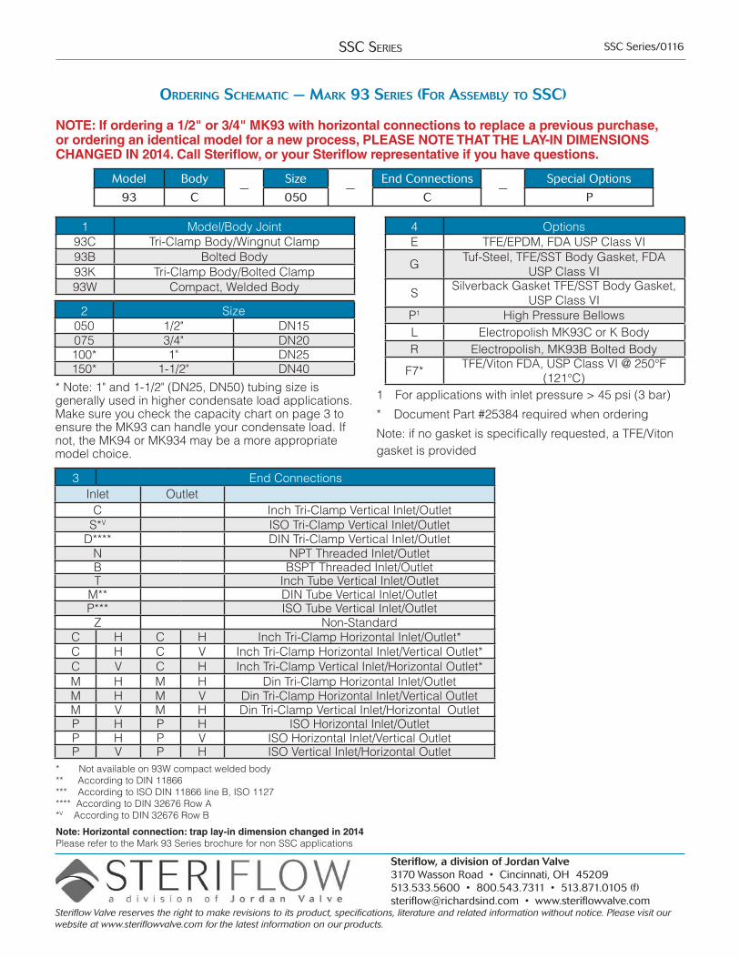
OrDering Schematic — mark 93 SerieS (fOr aSSemBly tO SSc)
NOTE: If ordering a 1/2" or 3/4" MK93 with horizontal connections to replace a previous purchase, or ordering an identical model for a new process, PLEASE NOTE THAT THE LAY-IN DIMENSIONS CHANGED IN 2014. Call Steriflow, or your Steriflow representative if you have questions.
Model Body—
Size—
End Connections—
Special Options
93 C 050 C P
1 Model/Body Joint93C Tri-Clamp Body/Wingnut Clamp93B Bolted Body93K Tri-Clamp Body/Bolted Clamp93W Compact, Welded Body
2 Size050 1/2" DN15075 3/4" DN20100* 1" DN25150* 1-1/2" DN40
* Note: 1" and 1-1/2" (DN25, DN50) tubing size is generally used in higher condensate load applications. Make sure you check the capacity chart on page 3 to ensure the MK93 can handle your condensate load. If not, the MK94 or MK934 may be a more appropriate model choice.
4 OptionsE TFE/EPDM, FDA USP Class VI
G Tuf-Steel, TFE/SST Body Gasket, FDA USP Class VI
S Silverback Gasket TFE/SST Body Gasket, USP Class VI
P1 High Pressure BellowsL Electropolish MK93C or K BodyR Electropolish, MK93B Bolted Body
F7* TFE/Viton FDA, USP Class VI @ 250°F (121°C)
1 For applications with inlet pressure > 45 psi (3 bar)
* Document Part #25384 required when ordering
Note: if no gasket is specifically requested, a TFE/Viton gasket is provided
3 End ConnectionsInlet Outlet
C Inch Tri-Clamp Vertical Inlet/OutletS*V ISO Tri-Clamp Vertical Inlet/Outlet
D**** DIN Tri-Clamp Vertical Inlet/OutletN NPT Threaded Inlet/OutletB BSPT Threaded Inlet/OutletT Inch Tube Vertical Inlet/Outlet
M** DIN Tube Vertical Inlet/OutletP*** ISO Tube Vertical Inlet/Outlet
Z Non-StandardC H C H Inch Tri-Clamp Horizontal Inlet/Outlet*C H C V Inch Tri-Clamp Horizontal Inlet/Vertical Outlet*C V C H Inch Tri-Clamp Vertical Inlet/Horizontal Outlet*M H M H Din Tri-Clamp Horizontal Inlet/OutletM H M V Din Tri-Clamp Horizontal Inlet/Vertical OutletM V M H Din Tri-Clamp Vertical Inlet/Horizontal OutletP H P H ISO Horizontal Inlet/OutletP H P V ISO Horizontal Inlet/Vertical OutletP V P H ISO Vertical Inlet/Horizontal Outlet
* Not available on 93W compact welded body ** According to DIN 11866*** According to ISO DIN 11866 line B, ISO 1127 **** According to DIN 32676 Row A*V According to DIN 32676 Row B
Note: Horizontal connection: trap lay-in dimension changed in 2014Please refer to the Mark 93 Series brochure for non SSC applications