subdivision code - city of shoalhaven · subdivision code – page i contents ... element ru3 –...
TRANSCRIPT
SCC Development & Environmental Services Group City Administrative Centre, Bridge Road, Nowra Telephone (02) 4429 3111 • Fax (02) 4429 3178 • Post: PO Box 42 Nowra 2541 Southern District Office, Deering Street, Ulladulla Telephone (02) 4429 8999 • Fax (02) 4429 8939 • Post: PO Box 737 Ulladulla 2539
[email protected] www.shoalhaven.nsw.gov.au 1262/01/02
SUBDIVISION
CODE (Development Control Plan 100)
Adopted18/12/01 – Minute 1749 – Effective 16/02/02 – File 5034

Subdivision Code – Page i
Contents PART 1 INTRODUCTION .................................................................................................................... 1
1.1 What is this plan called? ........................................................................................................... 1 1.2 Where does this plan apply? ..................................................................................................... 1 1.3 What is the purpose of this plan? ............................................................................................... 1 1.4 What are the aims of this plan? ................................................................................................. 1 1.5 What type of development does this plan cover?...................................................................... 1 1.6 How does this plan relate to other plans?.................................................................................. 1 2.0 How This Plan Works ............................................................................................................... 1 2.1 What does this plan contain?..................................................................................................... 1 2.2 Why has this format been selected? .......................................................................................... 2 2.3 How to use this plan.................................................................................................................. 2 2.4 How each design element works............................................................................................... 3
PART 2 DESIGN ELEMENTS.............................................................................................................. 4 Element RE1 – Site Analysis Urban ................................................................................................... 4 Element RE2 – Residential Neighbourhood Design........................................................................... 6 Element RE3 – Major Street Networks............................................................................................... 8 Element RE4 – Local Street Network.............................................................................................. 10 Element RE5 – Pedestrian and Cyclist Facilities.............................................................................. 15 Element RE6 – Public Transport ...................................................................................................... 18 Element RE7 – Public Open Space................................................................................................... 20 Element RE8 – Street Design............................................................................................................ 23 Element RE9 – Street and Common Driveway Construction........................................................... 40
Other Considerations.....................................................................................................................................42 Site Specific Requirements for Infill or Two Lot Subdivision........................................................42
Element RE10 – utility services........................................................................................................ 43 Other Considerations.....................................................................................................................................44
Water Supply, Sewerage, Electricity...............................................................................................44 General ......................................................................................................................................44 Dual Occupancy ........................................................................................................................44 Certificate of Compliance (CC).................................................................................................44 Design........................................................................................................................................44 Construction of Works...............................................................................................................44 Maintenance Bond.....................................................................................................................44 Pegging of Lot Boundaries.........................................................................................................44 Land Matters ..............................................................................................................................44 Electricity Supply and other Services Policy ..............................................................................44 Consent Conditions and Construction .......................................................................................45 Procedure Prior to Release of Survey Plan ................................................................................45 Other Utility Services ................................................................................................................45 Location of Utility Services.......................................................................................................45 Staged Development of Subdivisions ........................................................................................45 Design Requirements.................................................................................................................45
Element RE11 – Stormwater Drainage............................................................................................. 46 Other Considerations.....................................................................................................................................49
Drainage ..........................................................................................................................................49 Element RE12 – Stormwater Quality Management.......................................................................... 50
Page ii – Subdivision Code
Element RE13 – Streetscape..............................................................................................................52 Element RE14 – Allotment Layout ...................................................................................................54 Element RE15 – Bushfire Mitigation ................................................................................................65 Element RE16 – Geotechnical ...........................................................................................................67 Element RE17 – Subdivision of Buildings (Strata/Community Title Subdivision) ..........................68
Other Considerations .....................................................................................................................................68 Element RU1 – General.....................................................................................................................69 Element RU2 –Site Analysis – Rural ................................................................................................70 Element RU3 – Rural Road Network ................................................................................................71
Other Considerations .....................................................................................................................................72 Standard requirements for the provision of legal access to development properties. ..................... 72
Element RU4 – Drainage...................................................................................................................74 Element RU5 – Rural Landscape.......................................................................................................75 Element RU6 – Bushfire....................................................................................................................78 Element RU7 – Rural Services ..........................................................................................................80
Other Considerations .....................................................................................................................................81 Utility Services (Rural)................................................................................................................... 81
Water Supply ............................................................................................................................ 81 Effluent Disposal ...................................................................................................................... 81 Electricity.................................................................................................................................. 81
Site Information Required for Major Drainage Structures ............................................................. 81 Element ID1 – Industrial Subdivision ...............................................................................................82 Element ID2 – Site Analysis..............................................................................................................83
Other Considerations .....................................................................................................................................84 Vehicle Parking .............................................................................................................................. 84
Element CE1 – Commercial Subdivision ..........................................................................................85 Element TO1 – Tourist Accommodation Subdivision.......................................................................86
PART 3 PROCEDURES .......................................................................................................................87 P1 Procedures................................................................................................................................87 P2 Applications .............................................................................................................................87 P3 Integrated Development...........................................................................................................87 P4 Complying Development .........................................................................................................87 P5 Determination of Applications.................................................................................................90 P6 Request for Reconsideration and/or Rights of Appeal.............................................................90 P7 Staging .....................................................................................................................................90 P8 Development/Subdivision Applications ..................................................................................90 P9 Fees and Charges .....................................................................................................................90
P9.1 Application Fees..............................................................................................................................90 P9.2 Contributions – Section 94 and Section 64......................................................................................90
P10 Approvals.................................................................................................................................90 P11 Occupational Health and Safety...............................................................................................91 P12 Workers Compensations ..........................................................................................................91 P13 Variations to Approval.............................................................................................................91 P14 Engineering Design Plans and Specifications..........................................................................91
P14.1 Construction Certificate...................................................................................................................91 P14.2 Plan Preparation...............................................................................................................................91 P14.3 Plans – Residential Roadworks .......................................................................................................91
Subdivision Code – Page iii
P14.4.1 Stormwater Drainage Plans .............................................................................................................92 P14.4.2 Plans, Long Sections, Cross Sections..............................................................................................93 P14.4.3 Contour Plans ..................................................................................................................................93 P14.4.4 Scales ..............................................................................................................................................93 P14.4.5 Flood Prone Areas...........................................................................................................................94
P15 Site Regrading......................................................................................................................... 94 P16 Water Supply and Sewerage Drawings................................................................................... 94 P17 Landscaping Plans................................................................................................................... 94 P18 Design and Construction Specifications ................................................................................. 95 P19 Erosion Control Measures....................................................................................................... 95 P20 Testing..................................................................................................................................... 95 P21 Compliance Certificate............................................................................................................ 95 P22 Contractors and Sub-Contractors ............................................................................................ 95
P22.1 Water Supply or Sewerage Cut-ins .................................................................................................95 P23 Inspections .............................................................................................................................. 96
P23.1 Site Regrading and Clearing............................................................................................................96 P23.2 Stormwater Drainage and Utility Service Conduits ........................................................................96 P23.3 Water and Sewer Mains ..................................................................................................................96 P23.4 Sub-grade ........................................................................................................................................96 P23.5 Kerb and Gutter...............................................................................................................................96 P23.6 Pavement Construction ...................................................................................................................96 P23.7 Pavement Surfacing.........................................................................................................................96
P24 Insurance ................................................................................................................................. 96 P25 Work-as-Executed Plans ......................................................................................................... 97
P25.1 General ............................................................................................................................................97 P25.2 Water Supply...................................................................................................................................97 P25.3 Sewerage .........................................................................................................................................97
P26 Subdivision Certificate............................................................................................................ 97 P27 Bonding of Works in Subdivision........................................................................................... 97
P27.1 Assessment of Bond Amount ..........................................................................................................98 P27.2 Reduction of Bond ..........................................................................................................................98
P28 Completion of Works and Certification.................................................................................. 98 P29 Maintenance of Works ............................................................................................................ 98 P30 Naming of Roads .................................................................................................................... 98
APPENDICES ...................................................................................................................................... 101 Appendix 1 – Application Guidelines – Residential Land Subdivision ......................................... 102 Appendix 2 – Application Guidelines – Rural Land Subdivision .................................................. 103 Appendix 3 – Glossary.................................................................................................................... 104 Appendix 4 – Forms........................................................................................................................ 105
Form 1 Work-as-Executed Plans Subdivision Engineering Works.........................................................105 Form 2 Certificate of Compliance Example Certificate .........................................................................106
Restriction As To User.................................................................................................................... 107 Right of Way ...........................................................................................................................107 Other options which may be included .....................................................................................107 Building Envelope ...................................................................................................................108 Building Colours......................................................................................................................108 Landscaping.............................................................................................................................108 Removal of Vegetation ............................................................................................................108 Building Height .......................................................................................................................108

Page iv – Subdivision Code
Bushfire................................................................................................................................... 108 Effluent Disposal .................................................................................................................... 109 Environmental......................................................................................................................... 109 Access ..................................................................................................................................... 109 Driveways – Rural .................................................................................................................. 110 Floor Level.............................................................................................................................. 110
Bibliography ..........................................................................................................................................111 Index.......................................................................................................................................................112
Subdivision Code – Page v
Tables Table 1. Classification of Streets......................................................................................................................11 Table 2. Location of Intersections ....................................................................................................................12 Table 3. Residential Streets and Road Types ...................................................................................................24 Table 4. Traffic Speed ......................................................................................................................................25 Table 5-1. Bends or Curves..............................................................................................................................27 Table 5-2. Combination Alignment..................................................................................................................27 Table 6. Minimum Deflection Angles for Speed Control to 20km/h...............................................................28 Table 7. Minimum Stopping Distances ............................................................................................................30 Table 8. Street Classification – Industrial ........................................................................................................84 Table 9. Integrated Development .....................................................................................................................88
Figures Figure 1. Open space links ...............................................................................................................................22 Figure 2. Carriage Width..................................................................................................................................22 Figure 3. Measures to control speed.................................................................................................................28 Figure 4. Street Design and Visibility ..............................................................................................................30 Figure 5. Options for Access onto Limited Access Roads...............................................................................31 Figure 6. Turning Areas ...................................................................................................................................34 Figure 6-1. Turning Circle 15m Diameter........................................................................................................34 Figure 6-2. Turning Circle 18m Diameter........................................................................................................34 Figure 6-3. Central Island with Parking in Island ............................................................................................35 Figure 6-4. “Combination” Turning Area ........................................................................................................35 Figure 6-5a. Central Island with Parking Adjacent ..........................................................................................36 Figure 6-5b. Central Island with Parking Adjacent..........................................................................................36 Figure 6-6. Three Point Turn and Rectangular Lots.........................................................................................37 Figure 6-7. Turning Area Extension.................................................................................................................37 Figure 6-8. Typical Manoeuvring Areas for “MRV” Truck ............................................................................38 Figure 7. Typical Street Parking Details ..........................................................................................................39 Figure 8. Stormwater quality control measures................................................................................................51 Figure 9. Fire Policy Principles ........................................................................................................................66 Figure 10. Access to Rural Allotments ............................................................................................................73 Figure 11. Rural Landscape..............................................................................................................................76 Figure 12. Rural Landscape..............................................................................................................................77 Figure 13. Rural / Residential Bushfire Protection ..........................................................................................79

Subdivision Code – Page 1
PART 1
INTRODUCTION
1.1 What is this plan called? The name of the Plan is the Shoalhaven Subdivision Development DCP No. 100 Subdivision Code.
1.2 Where does this plan apply? This DCP applies to the Shoalhaven Local Government Area (LGA) where subdivision is generally permissible with Council’s consent.
1.3 What is the purpose of this plan? The purpose of this DCP is to encourage appropriate development which provides quality subdivision design, optimising land use and minimising net infrastructure costs being consistent with the objective of the Environmental Planning and Assessment Act, 1979. These important objectives must be balanced against maintaining or improving amenity.
1.4 What are the aims of this plan? The aims of this DCP are:
To encourage high quality urban design and residential amenity;
To set appropriate environmental criteria for subdivision development;
To provide a comprehensive design approach for residential, rural, industrial and commercial subdivision;
To provide a user friendly document with flexible performance-based criteria to guide development; and
To provide for the ecologically sustainable subdivision of land.
1.5 What type of development does this plan cover?
This DCP applies to residential, rural, tourism, industrial, commercial and strata and community title subdivisions.
1.6 How does this plan relate to other plans?
Section 72 of the Environmental Planning and Assessment (EP&A) Act 1979 and Part 3 of the
regulations require this DCP to be consistent with the Shoalhaven Local Environmental Plan (LEP) 1985. Accordingly, this DCP is generally consistent with the provisions of the LEP and the Model Provisions contained in the EP&A Act. In the event of any inconsistency, the provisions of the LEP shall prevail. This plan must also be read in conjunction with the relevant provisions of the Illawarra Regional Plan No. 1, the Jervis Bay Regional Environmental Plan No. 1 and any relevant State Environmental Planning Policy applying to the land for which a subdivision application is being made. To encourage good overall design it is also important that linkages are made between this DCP and other various codes and policies in place, eg. Medium Density Housing DCP No. 71. Integrated developments incorporating subdivision layout and the design and siting of dwellings concurrently are encouraged. Development applications for subdivision are also subject to Council’s Section 94 Contributions Plan 1993. Applicants may therefore need to contribute to the following works and services in accordance with this plan:
Roads and Traffic Control Drainage and Stormwater Pollution Passive Recreation Active Recreation City Wide Emergency Services Bushfire Protection Community Facilities Section 94 Plan Administration
For further information refer to Council’s Section 94 Contribution Plan and its supporting manual.
2.0 How This Plan Works 2.1 What does this plan contain? This DCP consists of five basic elements as follows:
Residential Subdivision RE1 to RE16 Rural Subdivision RU1 to RU6 Tourist Accommodation TO1 Industrial Subdivision ID1 Commercial Subdivision CE1 Procedures P1 to P29
Page 2 – Subdivision Code
Step 2 Determine whether IREP, JBREP, State Policies or any other DCPs or Council Policies apply to the site
The introductory and explanatory material indicates the purpose and objectives of the DCP, its relationship to other planning instruments and documents and the type of development covered by the Plan. (See Sections 1 & 2). Step 3 Carefully work through the design
elements of this DCP Subdivisions are divided into four groupings, residential, rural, industrial and commercial. Each section is then divided into subsections which include:
The design elements are arranged to work down from broad considerations affecting neighbourhood and streetscape to detailed considerations within the development site. Within each design element, designers should work through the following steps: Neighbourhood planning
Stormwater management Step 4 Read the objective of the particular design element. Physical infrastructure
Streetscape and lot layout Step 5 Read the performance criteria of the particular design element. Tourism
Step 6 Whilst it is not essential to study the acceptable solutions, these do contain useful examples of how the objectives and performance criteria may be satisfied.
Part 3 of this Plan lists the information required with an application, plan specification and procedures for the release of the plan of survey.
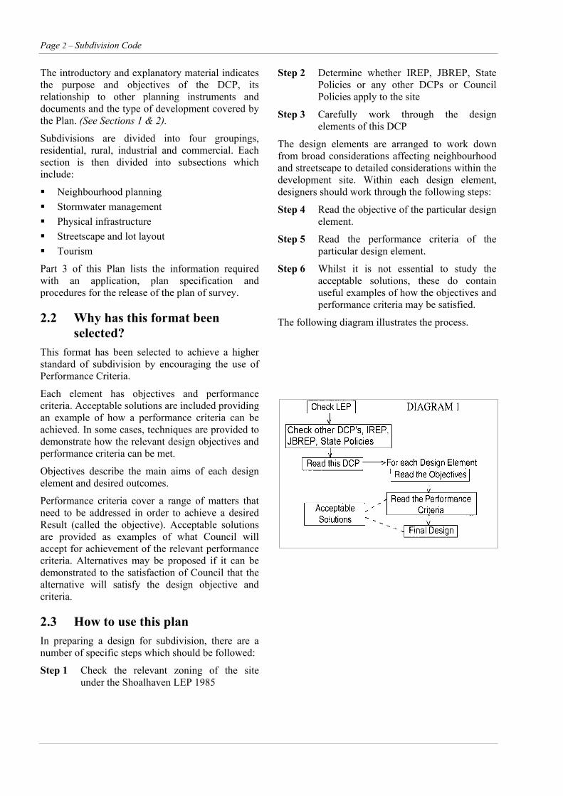
2.2 Why has this format been selected?
The following diagram illustrates the process.
This format has been selected to achieve a higher standard of subdivision by encouraging the use of Performance Criteria.
Each element has objectives and performance criteria. Acceptable solutions are included providing an example of how a performance criteria can be achieved. In some cases, techniques are provided to demonstrate how the relevant design objectives and performance criteria can be met.
Objectives describe the main aims of each design element and desired outcomes.
Performance criteria cover a range of matters that need to be addressed in order to achieve a desired Result (called the objective). Acceptable solutions are provided as examples of what Council will accept for achievement of the relevant performance criteria. Alternatives may be proposed if it can be demonstrated to the satisfaction of Council that the alternative will satisfy the design objective and criteria.
2.3 How to use this plan In preparing a design for subdivision, there are a number of specific steps which should be followed:
Step 1 Check the relevant zoning of the site under the Shoalhaven LEP 1985
Subdivision Code – Page 3
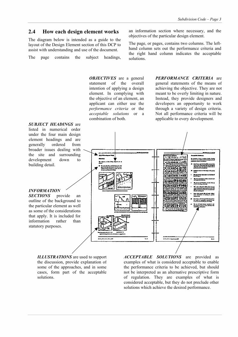
2.4 How each design element works The diagram below is intended as a guide to the layout of the Design Element section of this DCP to assist with understanding and use of the document.
The page contains the subject headings,
an information section where necessary, and the objectives of the particular design element.
The page, or pages, contains two columns. The left-hand column sets out the performance criteria and the right hand column indicates the acceptable solutions.
OBJECTIVES are a generalstatement of the overallintention of applying a designelement. In complying withthe objective of an element, anapplicant can either use theperformance criteria or theacceptable solutions or acombination of both.
PERFORMANCE CRITERIA aregeneral statements of the means ofachieving the objective. They are notmeant to be overly limiting in nature.Instead, they provide designers anddevelopers an opportunity to workthrough a variety of design criteria.Not all performance criteria will beapplicable to every development. SUBJECT HEADINGS are
listed in numerical orderunder the four main designelement headings and aregenerally ordered frombroader issues dealing withthe site and surroundingdevelopment down tobuilding detail.
INFORMATION SECTIONS provide anoutline of the background tothe particular element as wellas some of the considerationsthat apply. It is included forinformation rather thanstatutory purposes.
ILLUSTRATIONS are used to supportthe discussion, provide explanation ofsome of the approaches, and in somecases, form part of the acceptablesolutions.
ACCEPTABLE SOLUTIONS are provided asexamples of what is considered acceptable to enablethe performance criteria to be achieved, but shouldnot be interpreted as an alternative prescriptive formof regulation. They are examples of what isconsidered acceptable, but they do not preclude othersolutions which achieve the desired performance.
Page 4 – Subdivision Code
PART 2
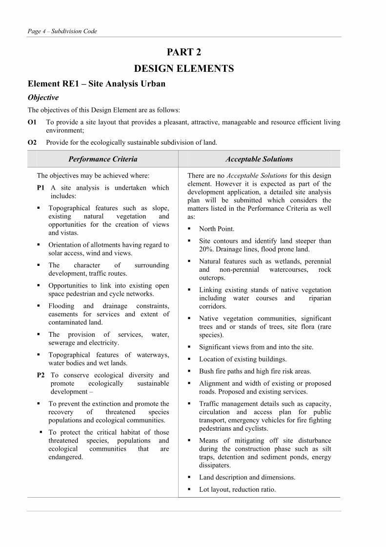
DESIGN ELEMENTS Element RE1 – Site Analysis Urban Objective The objectives of this Design Element are as follows:
O1 To provide a site layout that provides a pleasant, attractive, manageable and resource efficient living environment;
O2 Provide for the ecologically sustainable subdivision of land.
Performance Criteria Acceptable Solutions
The objectives may be achieved where:
P1 A site analysis is undertaken which includes:
Topographical features such as slope, existing natural vegetation and opportunities for the creation of views and vistas.
Orientation of allotments having regard to solar access, wind and views.
The character of surrounding development, traffic routes.
Opportunities to link into existing open space pedestrian and cycle networks.
Flooding and drainage constraints, easements for services and extent of contaminated land.
The provision of services, water, sewerage and electricity.
Topographical features of waterways, water bodies and wet lands.
P2 To conserve ecological diversity and promote ecologically sustainable development –
To prevent the extinction and promote the recovery of threatened species populations and ecological communities.
To protect the critical habitat of those threatened species, populations and ecological communities that are endangered.
There are no Acceptable Solutions for this design element. However it is expected as part of the development application, a detailed site analysis plan will be submitted which considers the matters listed in the Performance Criteria as well as:
North Point.
Site contours and identify land steeper than 20%. Drainage lines, flood prone land.
Natural features such as wetlands, perennial and non-perennial watercourses, rock outcrops.
Linking existing stands of native vegetation including water courses and riparian corridors.
Native vegetation communities, significant trees and or stands of trees, site flora (rare species).
Significant views from and into the site.
Location of existing buildings.
Bush fire paths and high fire risk areas.
Alignment and width of existing or proposed roads. Proposed and existing services.
Traffic management details such as capacity, circulation and access plan for public transport, emergency vehicles for fire fighting pedestrians and cyclists.
Means of mitigating off site disturbance during the construction phase such as silt traps, detention and sediment ponds, energy dissipaters.
Land description and dimensions.
Lot layout, reduction ratio.

Subdivision Code – Page 5
Element RE1 – Site Analysis Urban (cont’d)
Performance Criteria Acceptable Solutions
P2 (cont’d) –
To eliminate or manage certain processes that threaten the survival or evolutionary development of threatened species, populations and ecological communities.
To ensure that the impact of any action affecting threatened species, populations and ecological communities is properly assessed.
To encourage the conservation of threatened species, populations and ecological communities by adoptions of measures involving cooperative management.
Site analysis for threatened species and or their habitats.
Page 6 – Subdivision Code
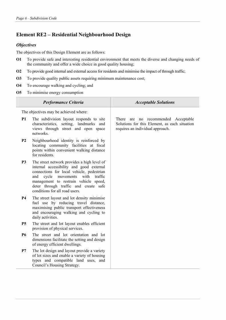
Element RE2 – Residential Neighbourhood Design
Objectives The objectives of this Design Element are as follows:
O1 To provide safe and interesting residential environment that meets the diverse and changing needs of the community and offer a wide choice in good quality housing;
O2 To provide good internal and external access for residents and minimise the impact of through traffic;
O3 To provide quality public assets requiring minimum maintenance cost;
O4 To encourage walking and cycling; and
O5 To minimise energy consumption
Performance Criteria Acceptable Solutions
The objectives may be achieved where:
P1 The subdivision layout responds to site characteristics, setting, landmarks and views through street and open space networks.
There are no recommended Acceptable Solutions for this Element, as each situation requires an individual approach.
P2 Neighbourhood identity is reinforced by locating community facilities at focal points within convenient walking distance for residents.
P3 The street network provides a high level of internal accessibility and good external connections for local vehicle, pedestrian and cycle movements with traffic management to restrain vehicle speed, deter through traffic and create safe conditions for all road users.
P4 The street layout and lot density minimise fuel use by reducing travel distance, maximising public transport effectiveness and encouraging walking and cycling to daily activities.
P5 The street and lot layout enables efficient provision of physical services.
P6 The street and lot orientation and lot dimensions facilitate the setting and design of energy efficient dwellings.
P7 The lot design and layout provide a variety of lot sizes and enable a variety of housing types and compatible land uses, and Council’s Housing Strategy.
Subdivision Code – Page 7
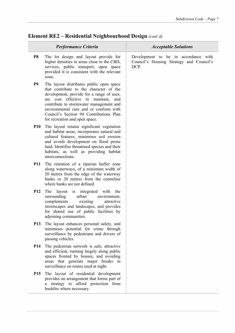
Element RE2 – Residential Neighbourhood Design (cont’d)
Performance Criteria Acceptable Solutions
P8 The lot design and layout provide for higher densities in areas close to the CBD, services, public transport, open space provided it is consistent with the relevant zone.
Development to be in accordance with Council’s Housing Strategy and Council’s DCP.
P9 The layout distributes public open space that contribute to the character of the development, provide for a range of uses, are cost effective to maintain, and contribute to stormwater management and environmental care and or conform with Council’s Section 94 Contributions Plan for recreation and open space.
P10 The layout retains significant vegetation and habitat areas, incorporates natural and cultural features, minimises soil erosion and avoids development on flood prone land. Identifies threatened species and their habitats, as well as providing habitat interconnections.
P11 The retention of a riparian buffer zone along waterways, of a minimum width of 20 metres from the edge of the waterway banks or 20 metres from the centreline where banks are not defined.
P12 The layout is integrated with the surrounding urban environment, complements existing attractive streetscapes and landscapes, and provides for shared use of public facilities by adjoining communities.
P13 The layout enhances personal safety, and minimises potential for crime through surveillance by pedestrians and drivers of passing vehicles.
P14 The pedestrian network is safe, attractive and efficient, running largely along public spaces fronted by houses, and avoiding areas that generate major breaks in surveillance on routes used at night.
P15 The layout of residential development provides an arrangement that forms part of a strategy to afford protection from bushfire where necessary.
Page 8 – Subdivision Code
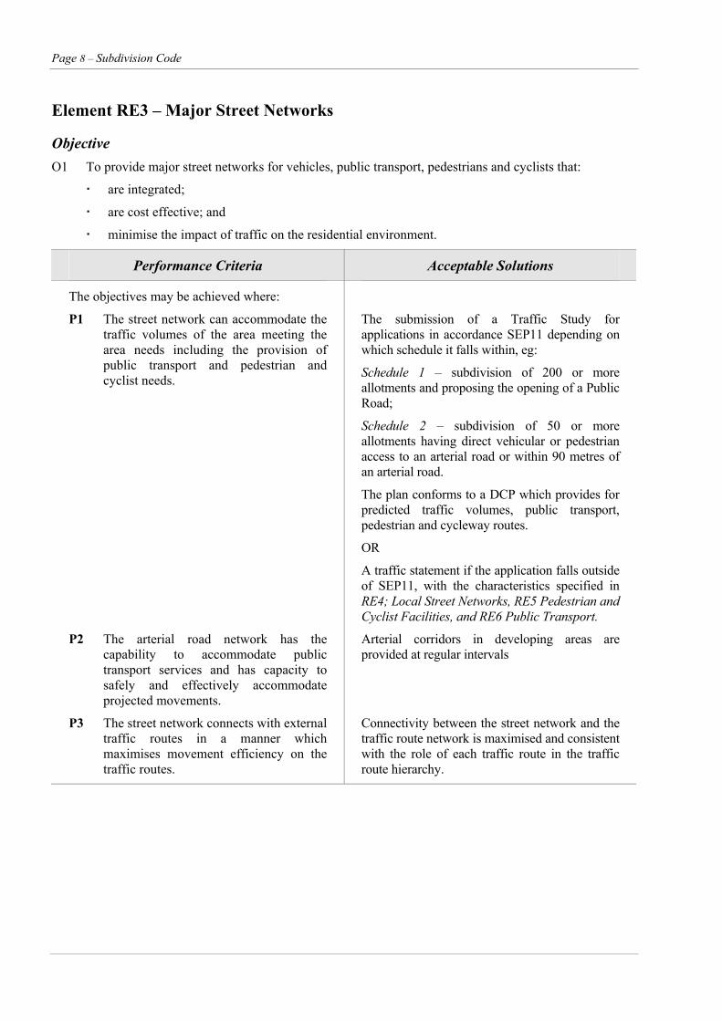
Element RE3 – Major Street Networks
Objective O1 To provide major street networks for vehicles, public transport, pedestrians and cyclists that:
are integrated;
are cost effective; and
minimise the impact of traffic on the residential environment.
Performance Criteria Acceptable Solutions
The objectives may be achieved where:
P1 The street network can accommodate the traffic volumes of the area meeting the area needs including the provision of public transport and pedestrian and cyclist needs.
The submission of a Traffic Study for applications in accordance SEP11 depending on which schedule it falls within, eg:
Schedule 1 – subdivision of 200 or more allotments and proposing the opening of a Public Road;
Schedule 2 – subdivision of 50 or more allotments having direct vehicular or pedestrian access to an arterial road or within 90 metres of an arterial road.
The plan conforms to a DCP which provides for predicted traffic volumes, public transport, pedestrian and cycleway routes.
OR
A traffic statement if the application falls outside of SEP11, with the characteristics specified in RE4; Local Street Networks, RE5 Pedestrian and Cyclist Facilities, and RE6 Public Transport.
P2 The arterial road network has the capability to accommodate public transport services and has capacity to safely and effectively accommodate projected movements.
Arterial corridors in developing areas are provided at regular intervals
P3 The street network connects with external traffic routes in a manner which maximises movement efficiency on the traffic routes.
Connectivity between the street network and the traffic route network is maximised and consistent with the role of each traffic route in the traffic route hierarchy.
Subdivision Code – Page 9
Element RE3 – Major Street Networks (cont’d)
Performance Criteria Acceptable Solutions
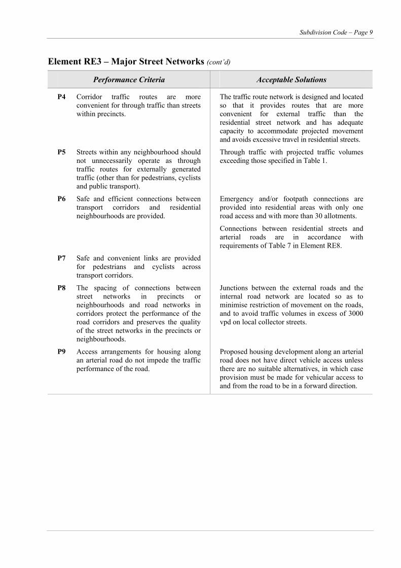
P4 Corridor traffic routes are more convenient for through traffic than streets within precincts.
The traffic route network is designed and located so that it provides routes that are more convenient for external traffic than the residential street network and has adequate capacity to accommodate projected movement and avoids excessive travel in residential streets.
P5 Streets within any neighbourhood should not unnecessarily operate as through traffic routes for externally generated traffic (other than for pedestrians, cyclists and public transport).
Through traffic with projected traffic volumes exceeding those specified in Table 1.
P6 Safe and efficient connections between transport corridors and residential neighbourhoods are provided.
Emergency and/or footpath connections are provided into residential areas with only one road access and with more than 30 allotments.
Connections between residential streets and arterial roads are in accordance with requirements of Table 7 in Element RE8.
P7 Safe and convenient links are provided for pedestrians and cyclists across transport corridors.
P8 The spacing of connections between street networks in precincts or neighbourhoods and road networks in corridors protect the performance of the road corridors and preserves the quality of the street networks in the precincts or neighbourhoods.
Junctions between the external roads and the internal road network are located so as to minimise restriction of movement on the roads, and to avoid traffic volumes in excess of 3000 vpd on local collector streets.
P9 Access arrangements for housing along an arterial road do not impede the traffic performance of the road.
Proposed housing development along an arterial road does not have direct vehicle access unless there are no suitable alternatives, in which case provision must be made for vehicular access to and from the road to be in a forward direction.
Page 10 – Subdivision Code
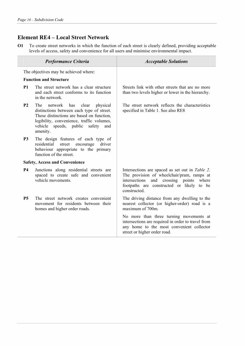
Element RE4 – Local Street Network O1 To create street networks in which the function of each street is clearly defined, providing acceptable
levels of access, safety and convenience for all users and minimise environmental impact.
Performance Criteria Acceptable Solutions
The objectives may be achieved where:
Function and Structure
P1 The street network has a clear structure and each street conforms to its function in the network.
Streets link with other streets that are no more than two levels higher or lower in the hierarchy.
P2 The network has clear physical distinctions between each type of street. These distinctions are based on function, legibility, convenience, traffic volumes, vehicle speeds, public safety and amenity.
The street network reflects the characteristics specified in Table 1. See also RE8
P3 The design features of each type of residential street encourage driver behaviour appropriate to the primary function of the street.
Safety, Access and Convenience
P4 Junctions along residential streets are spaced to create safe and convenient vehicle movements.
Intersections are spaced as set out in Table 2. The provision of wheelchair/pram, ramps at intersections and crossing points where footpaths are constructed or likely to be constructed.
P5 The street network creates convenient movement for residents between their homes and higher order roads.
The driving distance from any dwelling to the nearest collector (or higher-order) road is a maximum of 700m.
No more than three turning movements at intersections are required in order to travel from any home to the most convenient collector street or higher order road.
Subdivision Code – Page 11
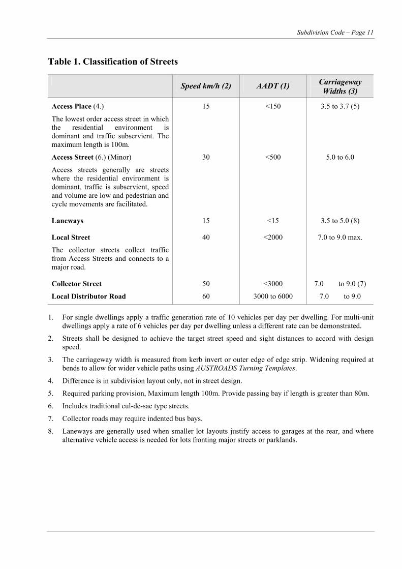
Table 1. Classification of Streets
Speed km/h (2) AADT (1) Carriageway Widths (3)
Access Place (4.)
The lowest order access street in which the residential environment is dominant and traffic subservient. The maximum length is 100m.
15 <150 3.5 to 3.7 (5)
Access Street (6.) (Minor)
Access streets generally are streets where the residential environment is dominant, traffic is subservient, speed and volume are low and pedestrian and cycle movements are facilitated.
30 <500 5.0 to 6.0
Laneways 15 <15 3.5 to 5.0 (8)
Local Street
The collector streets collect traffic from Access Streets and connects to a major road.
40 <2000 7.0 to 9.0 max.
Collector Street
Local Distributor Road
50
60
<3000
3000 to 6000
7.0 to 9.0 (7)
7.0 to 9.0
1. For single dwellings apply a traffic generation rate of 10 vehicles per day per dwelling. For multi-unit dwellings apply a rate of 6 vehicles per day per dwelling unless a different rate can be demonstrated.
2. Streets shall be designed to achieve the target street speed and sight distances to accord with design speed.
3. The carriageway width is measured from kerb invert or outer edge of edge strip. Widening required at bends to allow for wider vehicle paths using AUSTROADS Turning Templates.
4. Difference is in subdivision layout only, not in street design.
5. Required parking provision, Maximum length 100m. Provide passing bay if length is greater than 80m.
6. Includes traditional cul-de-sac type streets.
7. Collector roads may require indented bus bays.
8. Laneways are generally used when smaller lot layouts justify access to garages at the rear, and where alternative vehicle access is needed for lots fronting major streets or parklands.
Page 12 – Subdivision Code
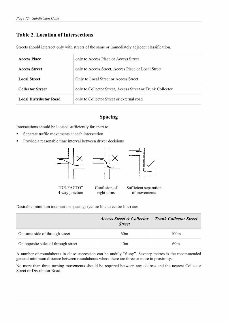
Table 2. Location of Intersections
Streets should intersect only with streets of the same or immediately adjacent classification.
Access Place only to Access Place or Access Street
Access Street only to Access Street, Access Place or Local Street
Local Street Only to Local Street or Access Street
Collector Street only to Collector Street, Access Street or Trunk Collector
Local Distributor Road only to Collector Street or external road
Spacing
Intersections should be located sufficiently far apart to:
Separate traffic movements at each intersection
Provide a reasonable time interval between driver decisions
“DE-FACTO” Confusion of Sufficient separation 4 way junction right turns of movements
Desirable minimum intersection spacings (centre line to centre line) are:
Access Street & Collector Street
Trunk Collector Street
On same side of through street 60m 100m
On opposite sides of through street 40m 60m
A number of roundabouts in close succession can be unduly “fussy”. Seventy metres is the recommended general minimum distance between roundabouts where there are three or more in proximity.
No more than three turning movements should be required between any address and the nearest Collector Street or Distributor Road.
Subdivision Code – Page 13
Element RE4 – Local Street Network (cont’d)
Performance Criteria Acceptable Solutions
Mode Choice
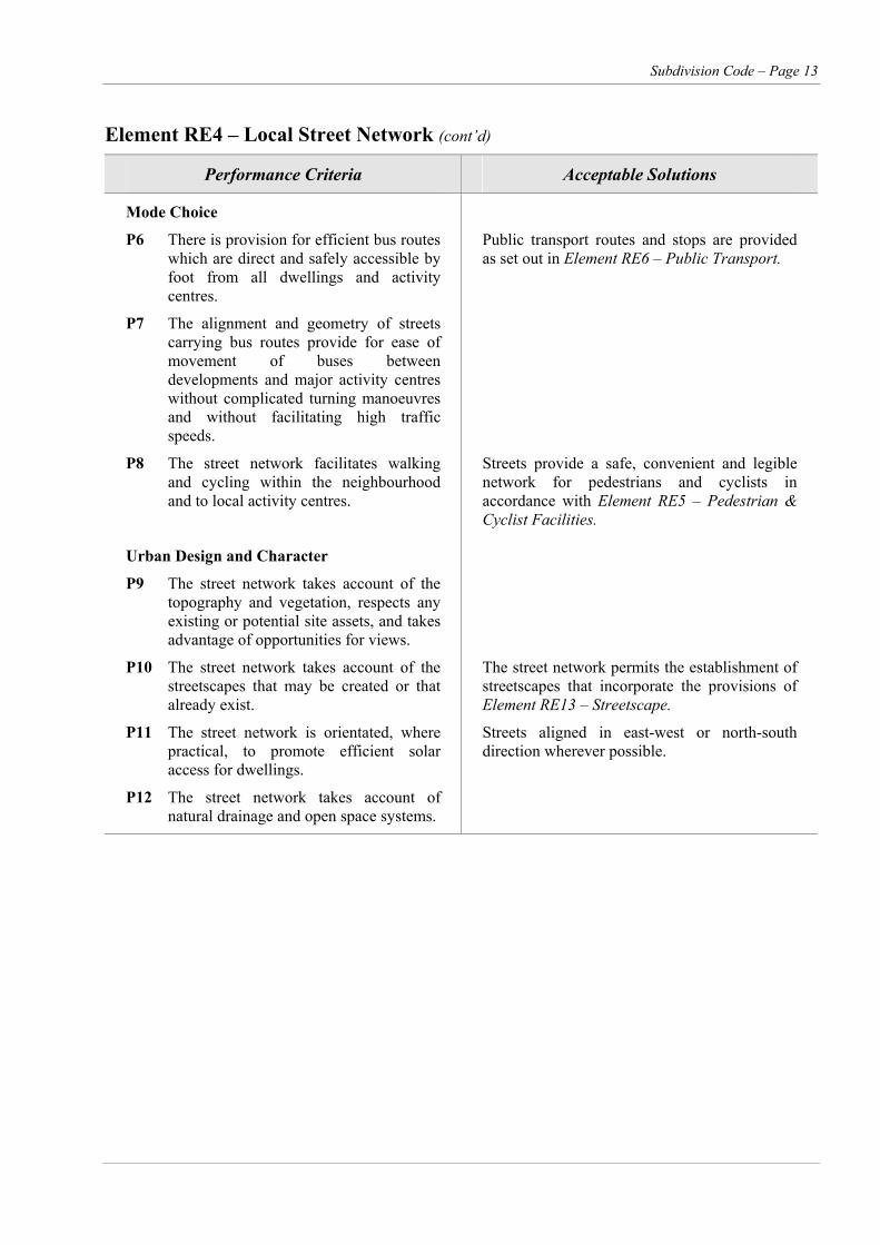
P6 There is provision for efficient bus routes which are direct and safely accessible by foot from all dwellings and activity centres.
Public transport routes and stops are provided as set out in Element RE6 – Public Transport.
P7 The alignment and geometry of streets carrying bus routes provide for ease of movement of buses between developments and major activity centres without complicated turning manoeuvres and without facilitating high traffic speeds.
P8 The street network facilitates walking and cycling within the neighbourhood and to local activity centres.
Streets provide a safe, convenient and legible network for pedestrians and cyclists in accordance with Element RE5 – Pedestrian & Cyclist Facilities.
Urban Design and Character
P9 The street network takes account of the topography and vegetation, respects any existing or potential site assets, and takes advantage of opportunities for views.
P10 The street network takes account of the streetscapes that may be created or that already exist.
The street network permits the establishment of streetscapes that incorporate the provisions of Element RE13 – Streetscape.
P11 The street network is orientated, where practical, to promote efficient solar access for dwellings.
Streets aligned in east-west or north-south direction wherever possible.
P12 The street network takes account of natural drainage and open space systems.
Page 14 – Subdivision Code
Element RE4 – Local Street Network (cont’d)
Performance Criteria Acceptable Solutions
Safety and Amenity
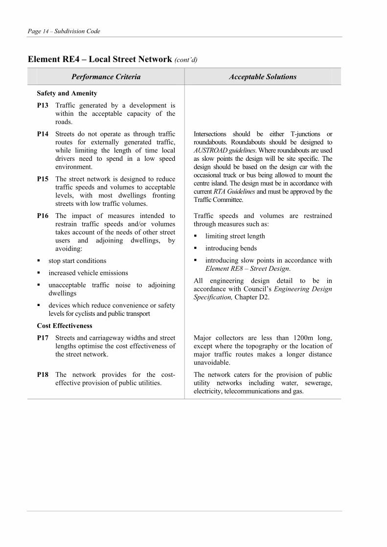
P13 Traffic generated by a development is within the acceptable capacity of the roads.
P14 Streets do not operate as through traffic routes for externally generated traffic, while limiting the length of time local drivers need to spend in a low speed environment.
P15 The street network is designed to reduce traffic speeds and volumes to acceptable levels, with most dwellings fronting streets with low traffic volumes.
Intersections should be either T-junctions or roundabouts. Roundabouts should be designed to AUSTROAD guidelines. Where roundabouts are used as slow points the design will be site specific. The design should be based on the design car with the occasional truck or bus being allowed to mount the centre island. The design must be in accordance with current RTA Guidelines and must be approved by the Traffic Committee.
P16 The impact of measures intended to restrain traffic speeds and/or volumes takes account of the needs of other street users and adjoining dwellings, by avoiding:
stop start conditions
increased vehicle emissions
unacceptable traffic noise to adjoining dwellings
devices which reduce convenience or safety levels for cyclists and public transport
Traffic speeds and volumes are restrained through measures such as:
limiting street length
introducing bends
introducing slow points in accordance with Element RE8 – Street Design.
All engineering design detail to be in accordance with Council’s Engineering Design Specification, Chapter D2.
Cost Effectiveness
P17 Streets and carriageway widths and street lengths optimise the cost effectiveness of the street network.
Major collectors are less than 1200m long, except where the topography or the location of major traffic routes makes a longer distance unavoidable.
P18 The network provides for the cost-effective provision of public utilities.
The network caters for the provision of public utility networks including water, sewerage, electricity, telecommunications and gas.
Subdivision Code – Page 15
Element RE5 – Pedestrian and Cyclist Facilities
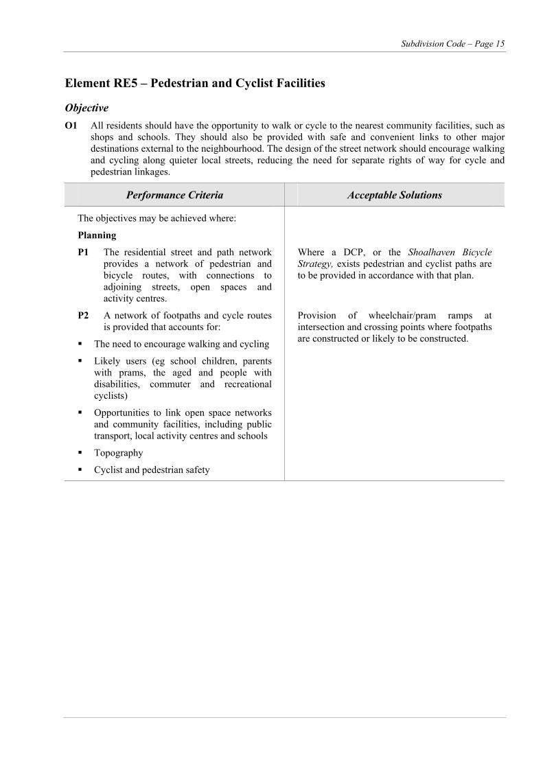
Objective O1 All residents should have the opportunity to walk or cycle to the nearest community facilities, such as
shops and schools. They should also be provided with safe and convenient links to other major destinations external to the neighbourhood. The design of the street network should encourage walking and cycling along quieter local streets, reducing the need for separate rights of way for cycle and pedestrian linkages.
Performance Criteria Acceptable Solutions
The objectives may be achieved where:
Planning
P1 The residential street and path network provides a network of pedestrian and bicycle routes, with connections to adjoining streets, open spaces and activity centres.
Where a DCP, or the Shoalhaven Bicycle Strategy, exists pedestrian and cyclist paths are to be provided in accordance with that plan.
P2 A network of footpaths and cycle routes is provided that accounts for:
The need to encourage walking and cycling
Likely users (eg school children, parents with prams, the aged and people with disabilities, commuter and recreational cyclists)
Opportunities to link open space networks and community facilities, including public transport, local activity centres and schools
Topography
Cyclist and pedestrian safety
Provision of wheelchair/pram ramps at intersection and crossing points where footpaths are constructed or likely to be constructed.
Page 16 – Subdivision Code
Element RE5 – Pedestrian and Cyclist Facilities (cont’d)
Performance Criteria Acceptable Solutions
Location and Design
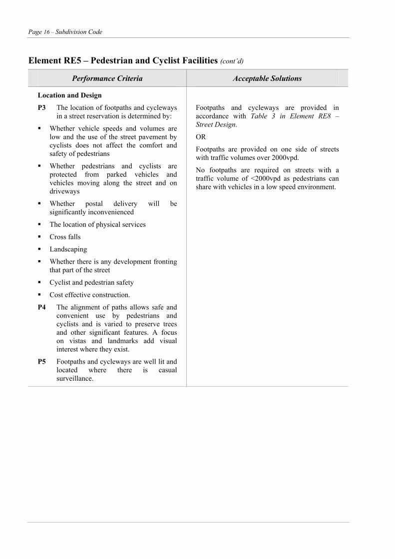
P3 The location of footpaths and cycleways in a street reservation is determined by:
Whether vehicle speeds and volumes are low and the use of the street pavement by cyclists does not affect the comfort and safety of pedestrians
Whether pedestrians and cyclists are protected from parked vehicles and vehicles moving along the street and on driveways
Whether postal delivery will be significantly inconvenienced
The location of physical services
Cross falls
Landscaping
Whether there is any development fronting that part of the street
Cyclist and pedestrian safety
Cost effective construction.
Footpaths and cycleways are provided in accordance with Table 3 in Element RE8 – Street Design.
OR
Footpaths are provided on one side of streets with traffic volumes over 2000vpd.
No footpaths are required on streets with a traffic volume of <2000vpd as pedestrians can share with vehicles in a low speed environment.
P4 The alignment of paths allows safe and convenient use by pedestrians and cyclists and is varied to preserve trees and other significant features. A focus on vistas and landmarks add visual interest where they exist.
P5 Footpaths and cycleways are well lit and located where there is casual surveillance.
Subdivision Code – Page 17
Element RE5 – Pedestrian and Cyclist Facilities (cont’d)
Performance Criteria Acceptable Solutions
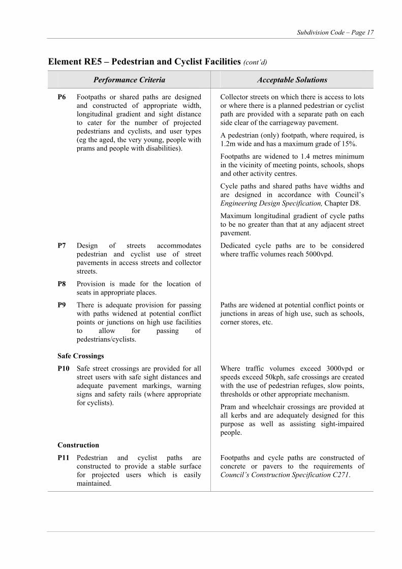
P6 Footpaths or shared paths are designed and constructed of appropriate width, longitudinal gradient and sight distance to cater for the number of projected pedestrians and cyclists, and user types (eg the aged, the very young, people with prams and people with disabilities).
Collector streets on which there is access to lots or where there is a planned pedestrian or cyclist path are provided with a separate path on each side clear of the carriageway pavement.
A pedestrian (only) footpath, where required, is 1.2m wide and has a maximum grade of 15%.
Footpaths are widened to 1.4 metres minimum in the vicinity of meeting points, schools, shops and other activity centres.
Cycle paths and shared paths have widths and are designed in accordance with Council’s Engineering Design Specification, Chapter D8.
Maximum longitudinal gradient of cycle paths to be no greater than that at any adjacent street pavement.
P7 Design of streets accommodates pedestrian and cyclist use of street pavements in access streets and collector streets.
Dedicated cycle paths are to be considered where traffic volumes reach 5000vpd.
P8 Provision is made for the location of seats in appropriate places.
P9 There is adequate provision for passing with paths widened at potential conflict points or junctions on high use facilities to allow for passing of pedestrians/cyclists.
Paths are widened at potential conflict points or junctions in areas of high use, such as schools, corner stores, etc.
Safe Crossings
P10 Safe street crossings are provided for all street users with safe sight distances and adequate pavement markings, warning signs and safety rails (where appropriate for cyclists).
Where traffic volumes exceed 3000vpd or speeds exceed 50kph, safe crossings are created with the use of pedestrian refuges, slow points, thresholds or other appropriate mechanism.
Pram and wheelchair crossings are provided at all kerbs and are adequately designed for this purpose as well as assisting sight-impaired people.
Construction
P11 Pedestrian and cyclist paths are constructed to provide a stable surface for projected users which is easily maintained.
Footpaths and cycle paths are constructed of concrete or pavers to the requirements of Council’s Construction Specification C271.
Page 18 – Subdivision Code
Element RE6 – Public Transport
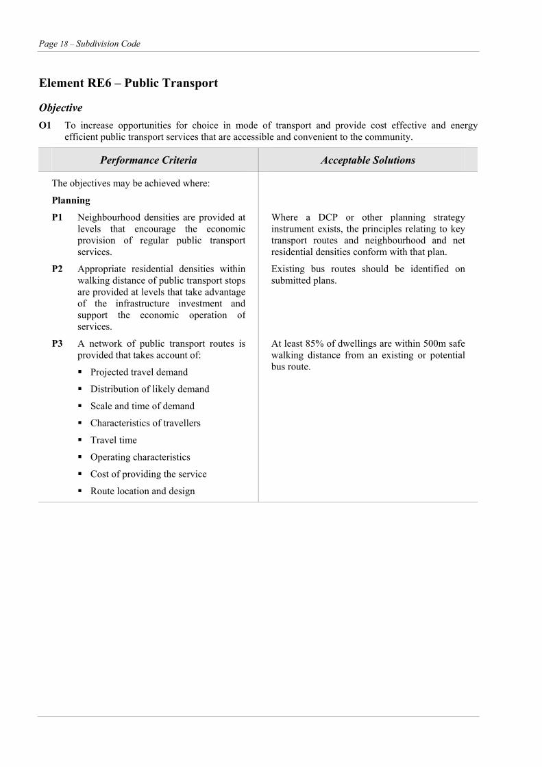
Objective O1 To increase opportunities for choice in mode of transport and provide cost effective and energy
efficient public transport services that are accessible and convenient to the community.
Performance Criteria Acceptable Solutions
The objectives may be achieved where:
Planning
P1 Neighbourhood densities are provided at levels that encourage the economic provision of regular public transport services.
P2 Appropriate residential densities within walking distance of public transport stops are provided at levels that take advantage of the infrastructure investment and support the economic operation of services.
Where a DCP or other planning strategy instrument exists, the principles relating to key transport routes and neighbourhood and net residential densities conform with that plan.
Existing bus routes should be identified on submitted plans.
P3 A network of public transport routes is provided that takes account of:
Projected travel demand
Distribution of likely demand
Scale and time of demand
Characteristics of travellers
Travel time
Operating characteristics
Cost of providing the service
Route location and design
At least 85% of dwellings are within 500m safe walking distance from an existing or potential bus route.
Subdivision Code – Page 19
Element RE6 – Public Transport (cont’d)
Performance Criteria Acceptable Solutions
Route location and design
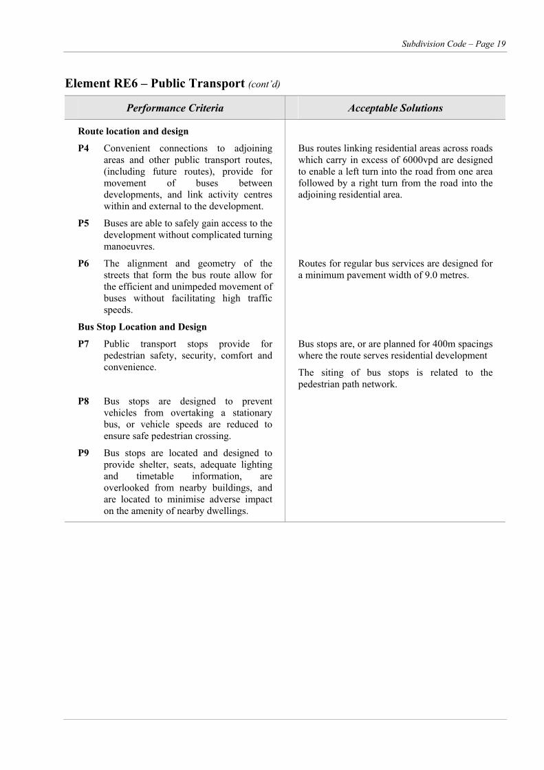
P4 Convenient connections to adjoining areas and other public transport routes, (including future routes), provide for movement of buses between developments, and link activity centres within and external to the development.
Bus routes linking residential areas across roads which carry in excess of 6000vpd are designed to enable a left turn into the road from one area followed by a right turn from the road into the adjoining residential area.
P5 Buses are able to safely gain access to the development without complicated turning manoeuvres.
P6 The alignment and geometry of the streets that form the bus route allow for the efficient and unimpeded movement of buses without facilitating high traffic speeds.
Routes for regular bus services are designed for a minimum pavement width of 9.0 metres.
Bus Stop Location and Design
P7 Public transport stops provide for pedestrian safety, security, comfort and convenience.
Bus stops are, or are planned for 400m spacings where the route serves residential development
The siting of bus stops is related to the pedestrian path network.
P8 Bus stops are designed to prevent vehicles from overtaking a stationary bus, or vehicle speeds are reduced to ensure safe pedestrian crossing.
P9 Bus stops are located and designed to provide shelter, seats, adequate lighting and timetable information, are overlooked from nearby buildings, and are located to minimise adverse impact on the amenity of nearby dwellings.
Page 20 – Subdivision Code
Element RE7 – Public Open Space
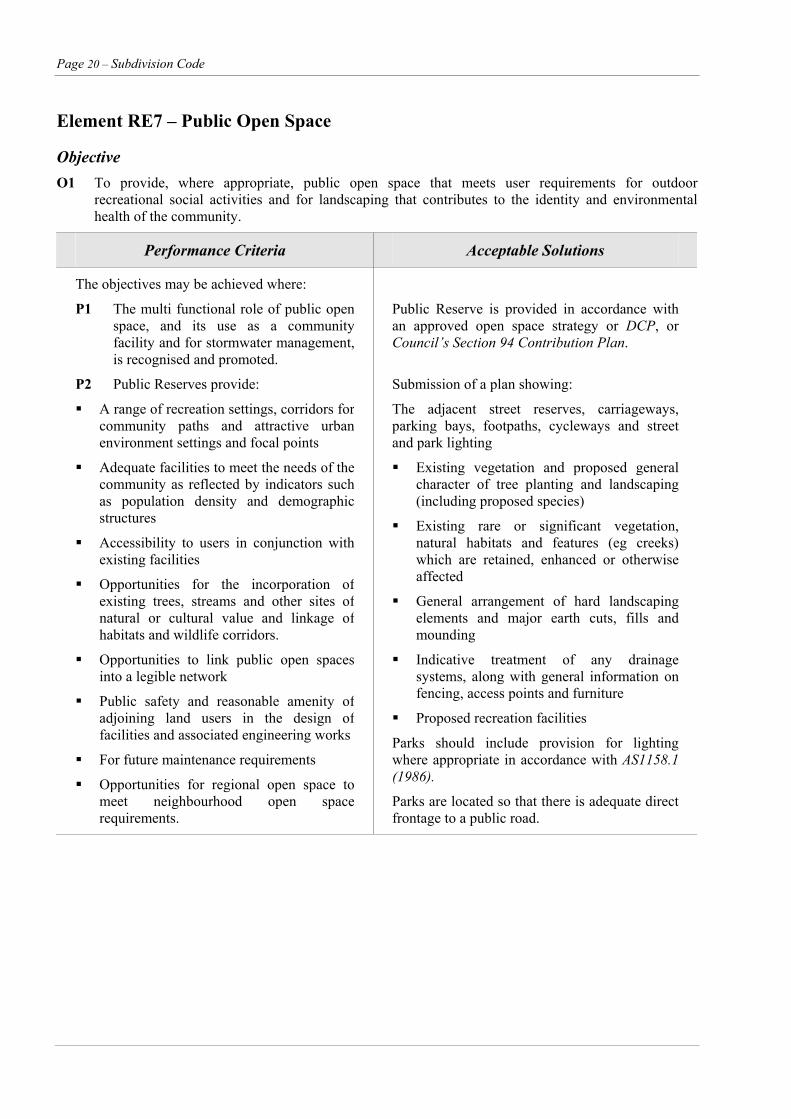
Objective O1 To provide, where appropriate, public open space that meets user requirements for outdoor
recreational social activities and for landscaping that contributes to the identity and environmental health of the community.
Performance Criteria Acceptable Solutions
The objectives may be achieved where:
P1 The multi functional role of public open space, and its use as a community facility and for stormwater management, is recognised and promoted.
Public Reserve is provided in accordance with an approved open space strategy or DCP, or Council’s Section 94 Contribution Plan.
P2 Public Reserves provide:
A range of recreation settings, corridors for community paths and attractive urban environment settings and focal points
Adequate facilities to meet the needs of the community as reflected by indicators such as population density and demographic structures
Accessibility to users in conjunction with existing facilities
Opportunities for the incorporation of existing trees, streams and other sites of natural or cultural value and linkage of habitats and wildlife corridors.
Opportunities to link public open spaces into a legible network
Public safety and reasonable amenity of adjoining land users in the design of facilities and associated engineering works
For future maintenance requirements
Opportunities for regional open space to meet neighbourhood open space requirements.
Submission of a plan showing:
The adjacent street reserves, carriageways, parking bays, footpaths, cycleways and street and park lighting
Existing vegetation and proposed general character of tree planting and landscaping (including proposed species)
Existing rare or significant vegetation, natural habitats and features (eg creeks) which are retained, enhanced or otherwise affected
General arrangement of hard landscaping elements and major earth cuts, fills and mounding
Indicative treatment of any drainage systems, along with general information on fencing, access points and furniture
Proposed recreation facilities
Parks should include provision for lighting where appropriate in accordance with AS1158.1 (1986).
Parks are located so that there is adequate direct frontage to a public road.
Subdivision Code – Page 21
Element RE7 – Public Open Space (cont’d)
Performance Criteria Acceptable Solutions
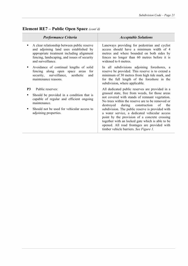
A clear relationship between public reserve and adjoining land uses established by appropriate treatment including alignment fencing, landscaping, and issues of security and surveillance.
Avoidance of continual lengths of solid fencing along open space areas for security, surveillance, aesthetic and maintenance reasons.
Laneways providing for pedestrian and cyclist access should have a minimum width of 4 metres and where bounded on both sides by fences no longer than 60 metres before it is widened to 6 metres.
In all subdivisions adjoining foreshores, a reserve be provided. This reserve is to extend a minimum of 30 metres from high tide mark, and for the full length of the foreshore in the subdivision, where applicable.
P3 Public reserves:
Should be provided in a condition that is capable of regular and efficient ongoing maintenance.
Should not be used for vehicular access to adjoining properties.
All dedicated public reserves are provided in a grassed state, free from weeds, for those areas not covered with stands of remnant vegetation. No trees within the reserve are to be removed or destroyed during construction of the subdivision. The public reserve is provided with a water service, a dedicated vehicular access point by the provision of a concrete crossing together with an locked gate which is able to be opened. All road frontages are provided with timber vehicle barriers. See Figure 1.
Page 22 – Subdivision Code
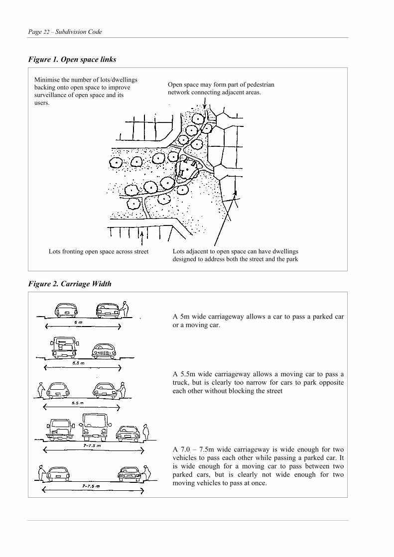
Figure 1. Open space links
Minimise the number of lots/dwellings backing onto open space to improve surveillance of open space and its users.
Open space may form part of pedestrian network connecting adjacent areas.
Lots adjacent to open space can have dwellings designed to address both the street and the park
Lots fronting open space across street
Figure 2. Carriage Width
A 5m wide carriageway allows a car to pass a parked car or a moving car.
A 5.5m wide carriageway allows a moving car to pass a truck, but is clearly too narrow for cars to park opposite each other without blocking the street
A 7.0 – 7.5m wide carriageway is wide enough for two vehicles to pass each other while passing a parked car. It is wide enough for a moving car to pass between two parked cars, but is clearly not wide enough for two moving vehicles to pass at once.
Subdivision Code – Page 23
Element RE8 – Street Design
Objective O1 To provide for streets that:
Fulfil their designated functions within the street network,
Accommodate public utility services,
Accommodate drainage systems, and
Create a safe and attractive environment.
Performance Criteria Acceptable Solutions
The objectives may be achieved where: All Engineering Design is to conform with Council’s Engineering Design Specification.
Engineering plans are to be signed by an engineer of NPER (Civil) standing or a registered surveyor accredited under the Survey Practice Accreditation Scheme (SPAS) as established by the Institution of Surveyors NSW Inc and Association of Consulting Surveyors NSW Inc.
Function and Width
P1 The design features of each type of residential street convey its primary function.
P2 The street reserve width is sufficient to cater for all street functions, including:
Safe and efficient movement of all users
Provision for parked vehicles
Provision of landscaping
Location, construction and maintenance of public utilities
The following minimum street component for each type of street are as specified in Tables 1 and 3; Figure 2.
Carriageway widths
Verge widths
Parking within street reserve
Kerb type
Pedestrian cyclist facilities
Longitudinal gradients
P3 The verge width is sufficient to provide for special site conditions and future requirements.
The verge width is increased where necessary to allow space for larger scale landscaping, indented parking, future carriageway widening, retaining walls, cycle paths or overland flow paths.
Page 24 – Subdivision Code
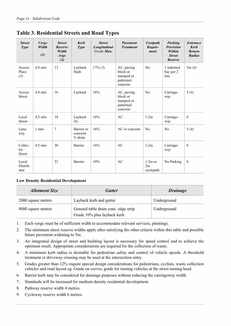
Table 3. Residential Streets and Road Types
Street Type
Verge Width
(1)
Street Reserve Width Avge (2)
Kerb Type
Street Longitudinal Grade Max.
Pavement Treatment
Footpath Requir-
ment
Parking Provision
Within Street
Reserve
Entrance Kerb
Return Radius
Access Place (3)
4.0 min 13 Layback flush
17% (5) AC, paving block or stamped or patterned concrete
No 1 indented bay per 2 lots
5m (4)
Access Street
4.0 min 16 Layback 16% AC, paving block or stamped or patterned concrete
No Carriage-way
5 (4)
Local Street
4.5 min 18 Layback (6)
16% AC 1.2m Carriage-way
6
Lane-way
1 min 7 Barrier or concrete V-drain
16% AC or concrete No No 5 (4)
Collec-tor Street
4.5 min 20 Barrier 16% AC 1.2m Carriage-way
8
Local Distrib-utor
22 Barrier 10% AC 1.2m or 2m cyclepath
No Parking 8
Low Density Residential Development
Allotment Size Gutter Drainage
2000 square metres Layback kerb and gutter Underground
4000 square metres Grassed table drain conc. edge strip Grade 10% plus layback kerb
Underground
1. Each verge must be of sufficient width to accommodate relevant services, plantings. 2. The minimum street reserve widths apply after satisfying the other criteria within this table and possible
future pavement widening to 5m. 3. An integrated design of street and building layout is necessary for speed control and to achieve the
optimum result. Appropriate considerations are required for the collection of waste. 4. A minimum kerb radius is desirable for pedestrian safety and control of vehicle speeds. A threshold
treatment or driveway crossing may be used at the intersection entry. 5. Grades greater than 12% require special design considerations for pedestrians, cyclists, waste collection
vehicles and road layout eg. Grade on curves, grade for turning vehicles at the street turning head. 6. Barrier kerb may be considered for drainage purposes without reducing the carriageway width. 7. Standards will be increased for medium density residential development. 8. Pathway reserve width 4 metres. 9. Cycleway reserve width 6 metres.
Subdivision Code – Page 25
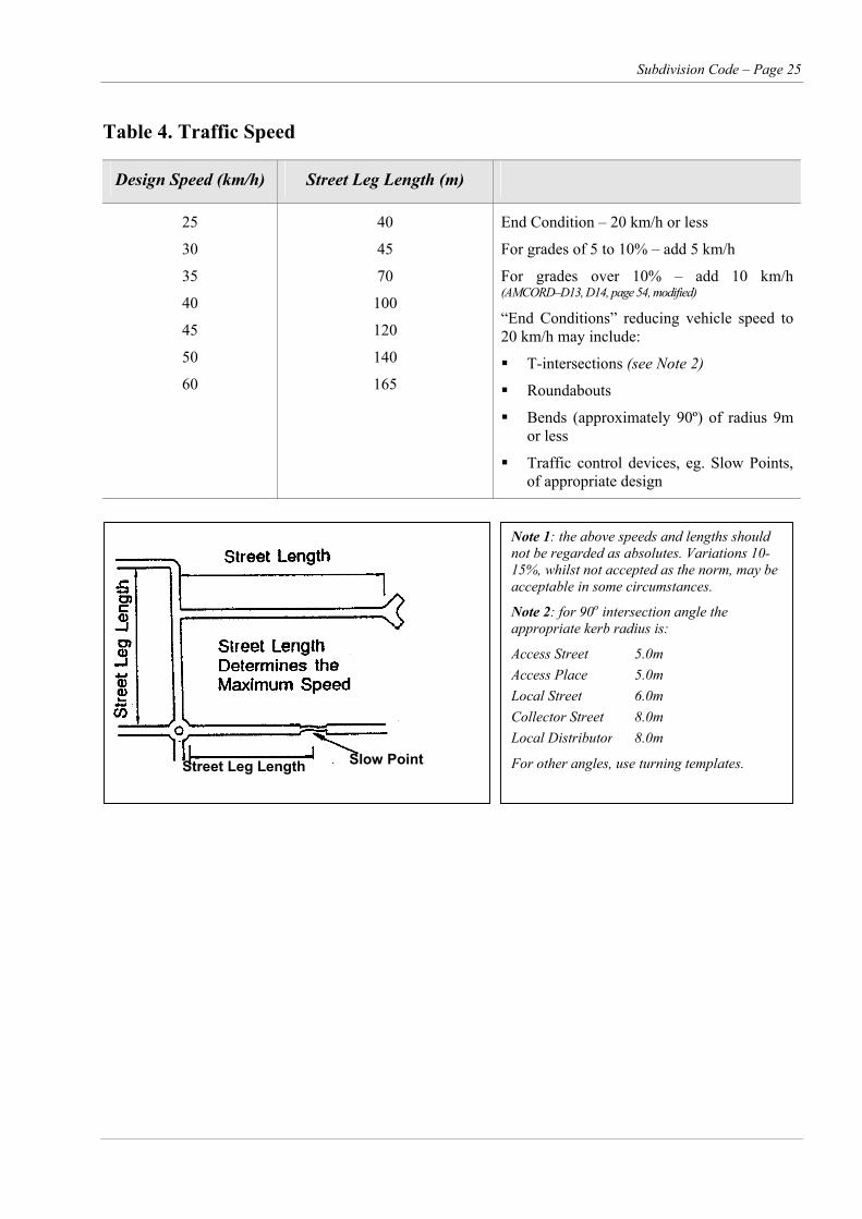
Table 4. Traffic Speed
Design Speed (km/h) Street Leg Length (m)
25
30
35
40
45
50
60
40
45
70
100
120
140
165
End Condition – 20 km/h or less
For grades of 5 to 10% – add 5 km/h
For grades over 10% – add 10 km/h(AMCORD–D13, D14, page 54, modified)
“End Conditions” reducing vehicle speed to 20 km/h may include:
T-intersections (see Note 2)
Roundabouts
Bends (approximately 90º) of radius 9m or less
Traffic control devices, eg. Slow Points, of appropriate design
Note 1: the above speeds and lengths should not be regarded as absolutes. Variations 10-15%, whilst not accepted as the norm, may be acceptable in some circumstances.
Note 2: for 90o intersection angle the appropriate kerb radius is:
Access Street 5.0m Access Place 5.0m Local Street 6.0m Collector Street 8.0m Local Distributor 8.0m
For other angles, use turning templates.
Slow Point Street Leg Length

Page 26 – Subdivision Code
Element RE8 – Street Design (cont’d)
Performance Criteria Acceptable Solutions
Designing for Safety
P4 The design facilitates safe use by pedestrians, particularly people with disabilities, the aged and children, by:
Providing a carriageway width which allows vehicles to proceed safely at the operating speed intended for that level of street
Making allowances for restrictions caused by on street parking
Providing a horizontal and vertical alignment which is not conducive to excessive speeds
Promoting the safety of pedestrians at bus stops and other crossing points
Promoting the safety of cyclists in streets and at crossing points
P5 Speed reduction techniques are used to achieve desired speeds, as part of a design for the whole street environment, and include the following principles:
Slow points using horizontal deflection are designed to slow traffic to design speeds
Slow points and carriageway narrowings are designed to take into account the needs of cyclists, by ensuring speed compatibility, adequate space for concurrent passage or off street diversions
Landscape design, on street parking and streetscape design are used to complement speed restriction measures
Speed restriction techniques and devices are not used in isolation
The verge provides safe sight distances, taking into account expected vehicle speeds and pedestrian and cyclist movements.
Traffic speeds and volumes are restrained through one or more of the following measures:
i. Limiting street length
Where street ‘leg’ length is limited to control vehicle speed, the lengths between slow points are designed to restrict operating speeds as specified in Table 4.
ii. Curved alignment
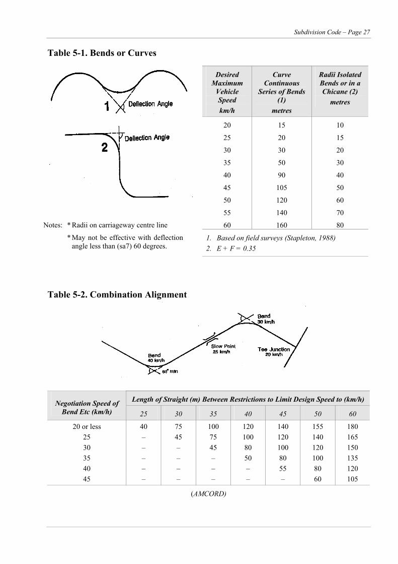
Where bends are introduced to control speeds to 20 km/h or less, the deflection angle in the change of the alignment of a street or pavement is at least the angle determined from Table 5.1.
iii. Introducing slow points
Where street ‘leg’ length is limited to control vehicle speed, the lengths between slow points are designed to restrict operating speeds as specified in Table 4.
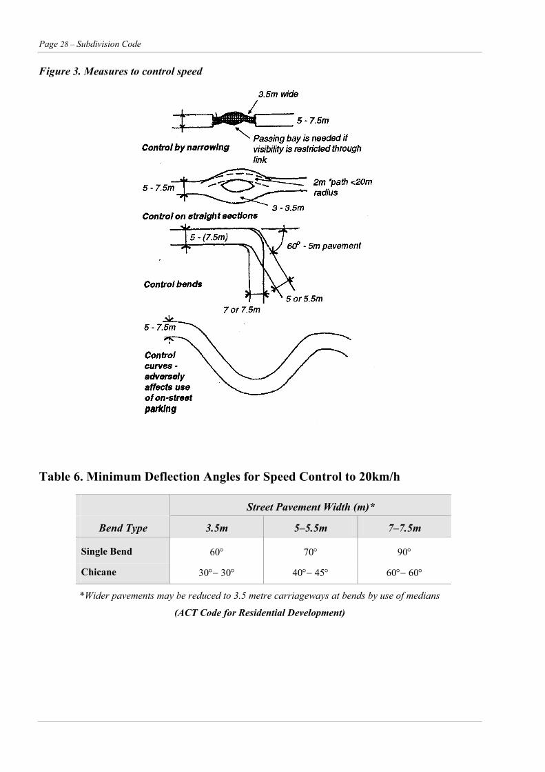
Where speed reduction devices are part of a design for the total street environment, devices conform with those in Figure 3.
Where speed restriction devices are used in isolation, they shall include:
Full horizontal displacement of the vehicle path
Swept vehicle paths to have a 20m radius
Construction on exit rather than on entry (otherwise there is a risk that the device may be short cut)
Additional pavement treatment behind the kerb for large vehicles
Line marking and signposting
Slow points to be designed in accordance with AS 1742.3.
Subdivision Code – Page 27
Table 5-1. Bends or Curves
Desired Maximum
Vehicle Speed km/h
Curve Continuous
Series of Bends (1)
metres
Radii Isolated Bends or in a Chicane (2)
metres
20
25
30
35
40
45
50
55
60
15
20
30
50
90
105
120
140
160
10
15
20
30
40
50
60
70
80
1. Based on field surveys (Stapleton, 1988) 2. E + F = 0.35
Notes: * Radii on carriageway centre line
* May not be effective with deflectionangle less than (sa7) 60 degrees.
Table 5-2. Combination Alignment
Length of Straight (m) Between Restrictions to Limit Design Speed to (km/h) Negotiation Speed of Bend Etc (km/h) 25 30 35 40 45 50 60
20 or less 40 75 100 120 140 155 180 25 – 45 75 100 120 140 165 30 – – 45 80 100 120 150 35 – – – 50 80 100 135 40 – – – – 55 80 120 45 – – – – – 60 105
(AMCORD)
Page 28 – Subdivision Code
Figure 3. Measures to control speed
Table 6. Minimum Deflection Angles for Speed Control to 20km/h
Street Pavement Width (m)*
Bend Type 3.5m 5–5.5m 7–7.5m
Single Bend 60° 70° 90°
Chicane 30°− 30° 40°− 45° 60°− 60°
*Wider pavements may be reduced to 3.5 metre carriageways at bends by use of medians
(ACT Code for Residential Development)

Subdivision Code – Page 29
Element RE3 – Street Design (cont’d)
Performance Criteria Acceptable Solutions
P6 Safe sight distances, based on vehicle travel speeds, exist at property access points, pedestrian and cyclist crossings and at junctions and intersections.
Driveway Access
P7 The carriageway and verge width allows for unobstructed access to individual lots, even when a car is parked on the opposite side of the street.
Driveway egress movements do not create a safety hazard.
Sight distances at pedestrian and cyclist crossings and at junctions/intersections conform with those set out in Figure 4.
Motorists can enter or reverse from a lot in a single movement.
Lot design enables driveways on major collector streets and streets which carry more than 3000vpd to be designed to promote forward movement of vehicles across the verge. (see Figure 5)

Page 30 – Subdivision Code
Figure 4. Street Design and Visibility
a. Priority Junctions and Driveways
Visibility uninterrupted by fixed objects to be provided over entire shaded area. Hilly terrain may require junctions to be moved onto or well away from crests to satisfy sight distance requirements.
Stopping distance Y (refer table below) is directly related to speed. Increased speed requires increased verge width to improve visibility of people or cars coming out of driveways or at intersections
b. Vertical Curves
c. Carriageway Edge
Planting with foliage in the height range of 0.6m to 2m should not restrict the available sight distance to less than Y (refer to table below) on streets with frontage access. 1.15m represents the standard driver eye height.
Table 7. Minimum Stopping Distances
Stopping Distance
Street Type
Target Speed Within Carriageway Intersection
Access place
Minor access street
Access street
Local collector
Minor and major distributor
15
30
40
50
60
5
20
30
40
55
60
80
105
Note: Assumes longitudinal gradient is less than 8%. Refer to AUSTROADS Guide to Traffic Engineering Practice Part 5: Intersections at Grade for additional information. Sight distances for junctions with traffic routes are provided in AUSTROADS 1988.
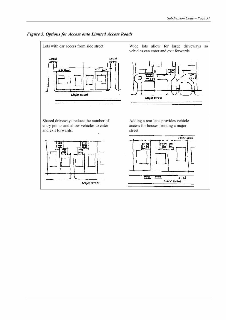
Subdivision Code – Page 31
Figure 5. Options for Access onto Limited Access Roads
Lots with car access from side street Wide lots allow for large driveways so vehicles can enter and exit forwards
Shared driveways reduce the number of Adding a rear lane provides vehicle entry points and allow vehicles to enter access for houses fronting a major. and exit forwards. street
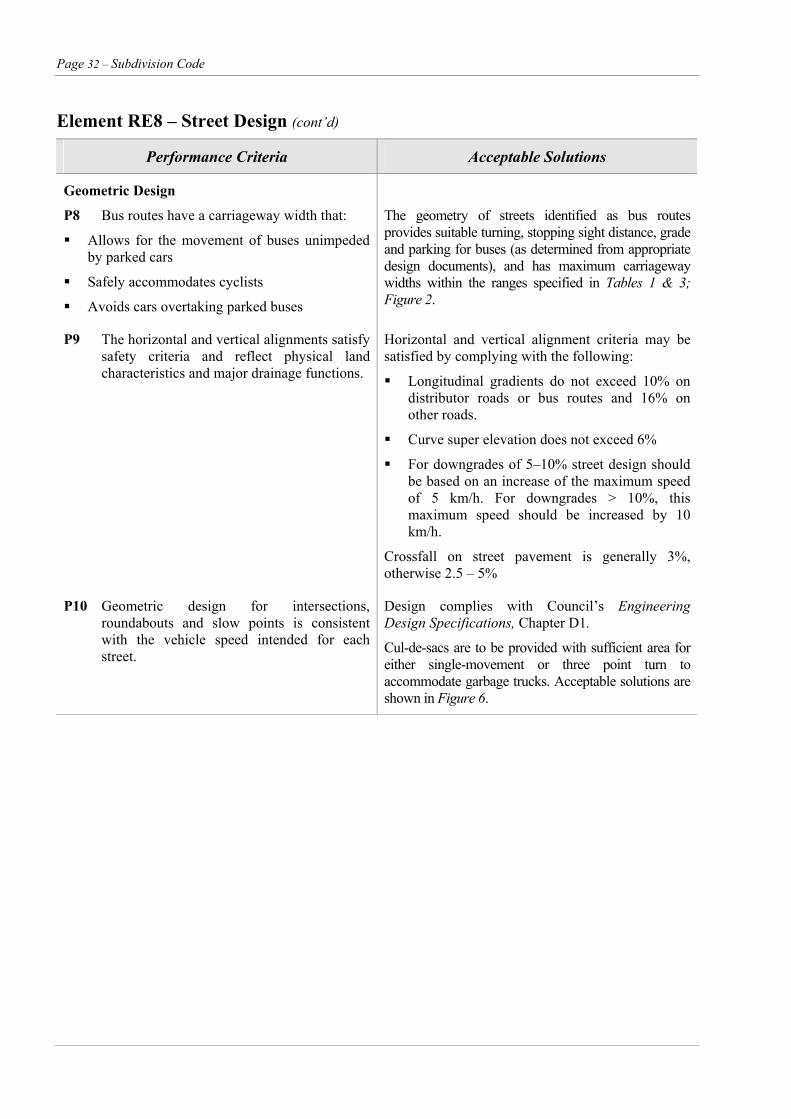
Page 32 – Subdivision Code
Element RE8 – Street Design (cont’d)
Performance Criteria Acceptable Solutions
Geometric Design
P8 Bus routes have a carriageway width that:
Allows for the movement of buses unimpeded by parked cars
Safely accommodates cyclists
Avoids cars overtaking parked buses
The geometry of streets identified as bus routes provides suitable turning, stopping sight distance, grade and parking for buses (as determined from appropriate design documents), and has maximum carriageway widths within the ranges specified in Tables 1 & 3; Figure 2.
P9 The horizontal and vertical alignments satisfy safety criteria and reflect physical land characteristics and major drainage functions.
Horizontal and vertical alignment criteria may be satisfied by complying with the following:
Longitudinal gradients do not exceed 10% on distributor roads or bus routes and 16% on other roads.
Curve super elevation does not exceed 6%
For downgrades of 5–10% street design should be based on an increase of the maximum speed of 5 km/h. For downgrades > 10%, this maximum speed should be increased by 10 km/h.
Crossfall on street pavement is generally 3%, otherwise 2.5 – 5%
P10 Geometric design for intersections, roundabouts and slow points is consistent with the vehicle speed intended for each street.
Design complies with Council’s Engineering Design Specifications, Chapter D1.
Cul-de-sacs are to be provided with sufficient area for either single-movement or three point turn to accommodate garbage trucks. Acceptable solutions are shown in Figure 6.
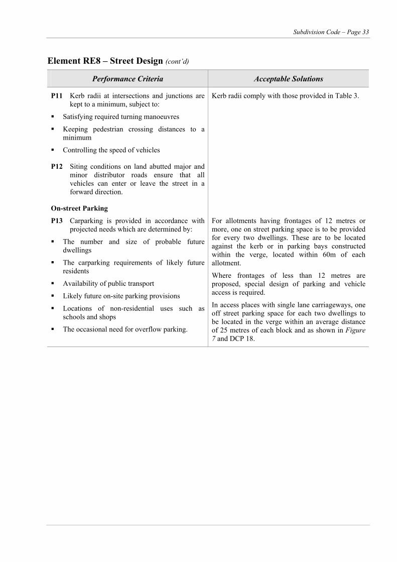
Subdivision Code – Page 33
Element RE8 – Street Design (cont’d)
Performance Criteria Acceptable Solutions
P11 Kerb radii at intersections and junctions are kept to a minimum, subject to:
Satisfying required turning manoeuvres
Keeping pedestrian crossing distances to a minimum
Controlling the speed of vehicles
Kerb radii comply with those provided in Table 3.
P12 Siting conditions on land abutted major and minor distributor roads ensure that all vehicles can enter or leave the street in a forward direction.
On-street Parking
P13 Carparking is provided in accordance with projected needs which are determined by:
The number and size of probable future dwellings
The carparking requirements of likely future residents
Availability of public transport
Likely future on-site parking provisions
Locations of non-residential uses such as schools and shops
The occasional need for overflow parking.
For allotments having frontages of 12 metres or more, one on street parking space is to be provided for every two dwellings. These are to be located against the kerb or in parking bays constructed within the verge, located within 60m of each allotment.
Where frontages of less than 12 metres are proposed, special design of parking and vehicle access is required.
In access places with single lane carriageways, one off street parking space for each two dwellings to be located in the verge within an average distance of 25 metres of each block and as shown in Figure 7 and DCP 18.
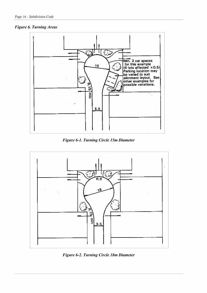
Page 34 – Subdivision Code
Figure 6. Turning Areas
Figure 6-1. Turning Circle 15m Diameter
Figure 6-2. Turning Circle 18m Diameter
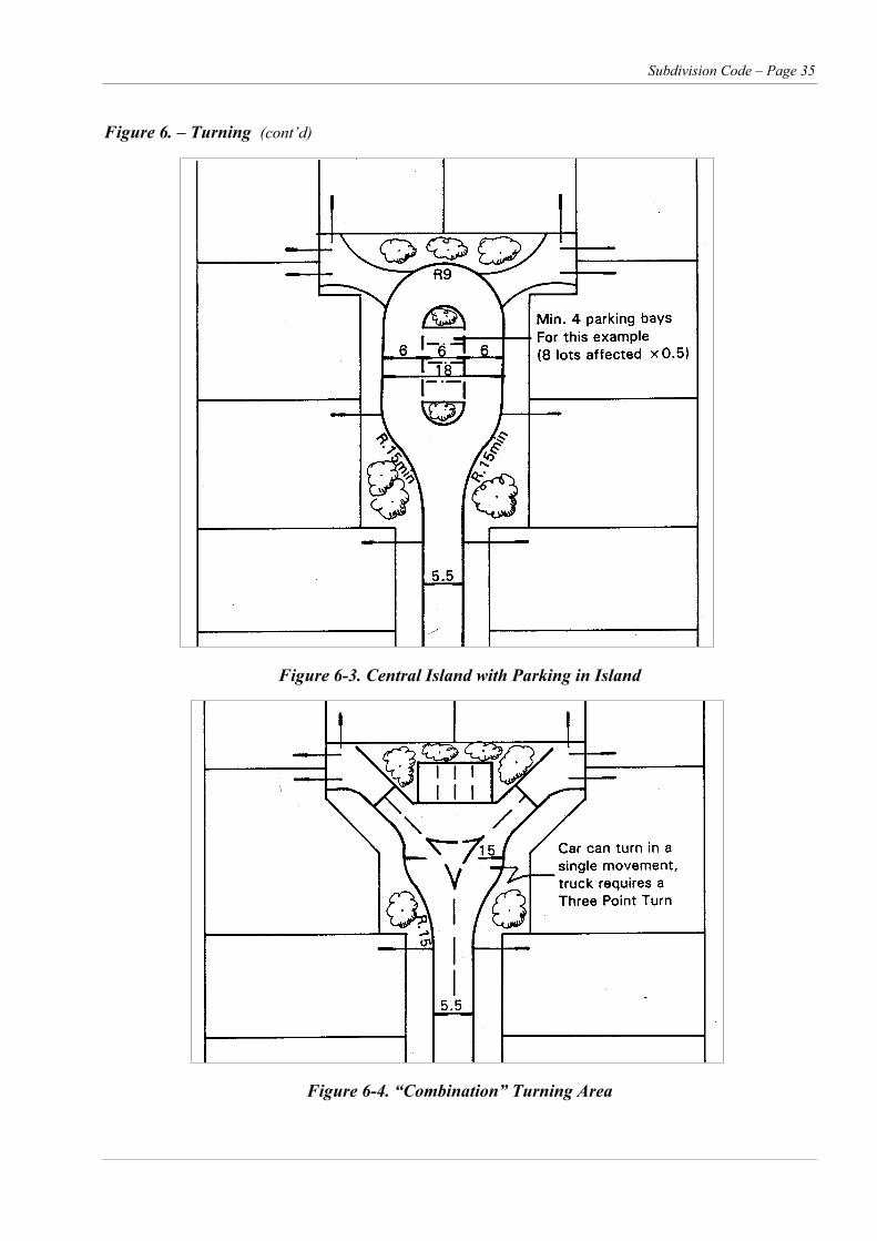
Subdivision Code – Page 35
Figure 6. – Turning (cont’d)
Figure 6-3. Central Island with Parking in Island
Figure 6-4. “Combination” Turning Area
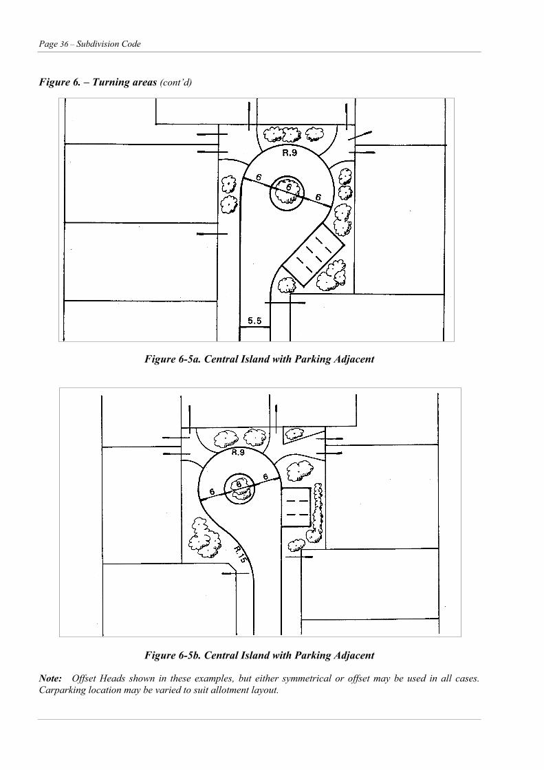
Page 36 – Subdivision Code
Figure 6. – Turning areas (cont’d)
Figure 6-5a. Central Island with Parking Adjacent
Figure 6-5b. Central Island with Parking Adjacent
Note: Offset Heads shown in these examples, but either symmetrical or offset may be used in all cases. Carparking location may be varied to suit allotment layout.
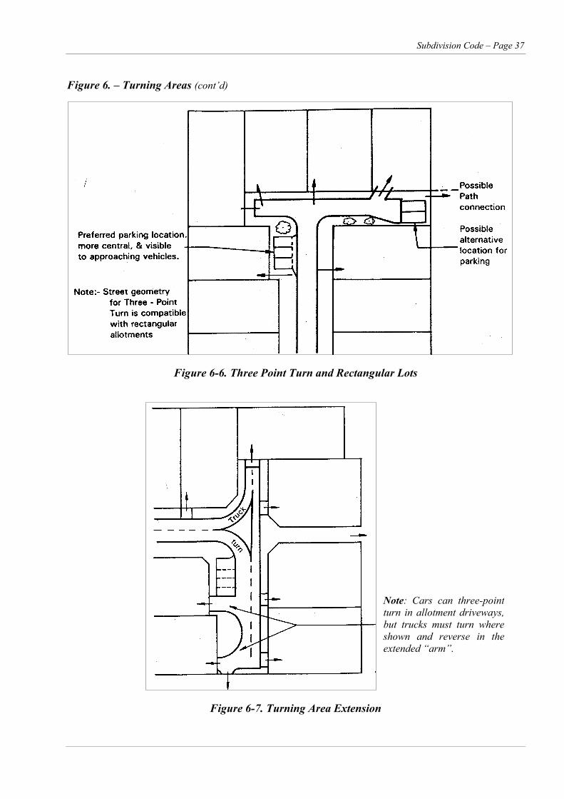
Subdivision Code – Page 37
Figure 6. – Turning Areas (cont’d)
Figure 6-6. Three Point Turn and Rectangular Lots
Note: Cars can three-pointturn in allotment driveways,but trucks must turn whereshown and reverse in theextended “arm”.
Figure 6-7. Turning Area Extension
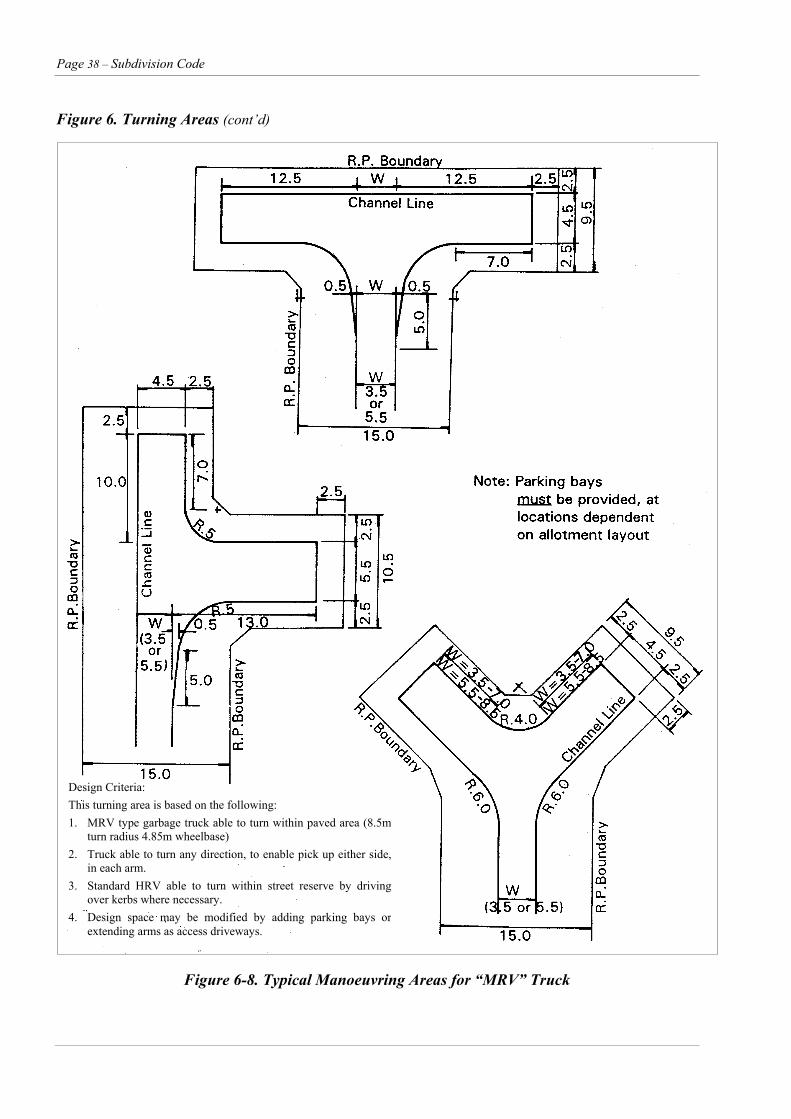
Page 38 – Subdivision Code
Figure 6. Turning Areas (cont’d)
Design Criteria: This turning area is based on the following: 1. MRV type garbage truck able to turn within paved area (8.5m
turn radius 4.85m wheelbase) 2. Truck able to turn any direction, to enable pick up either side,
in each arm. 3. Standard HRV able to turn within street reserve by driving
over kerbs where necessary. 4. Design space may be modified by adding parking bays or
extending arms as access driveways.
Figure 6-8. Typical Manoeuvring Areas for “MRV” Truck
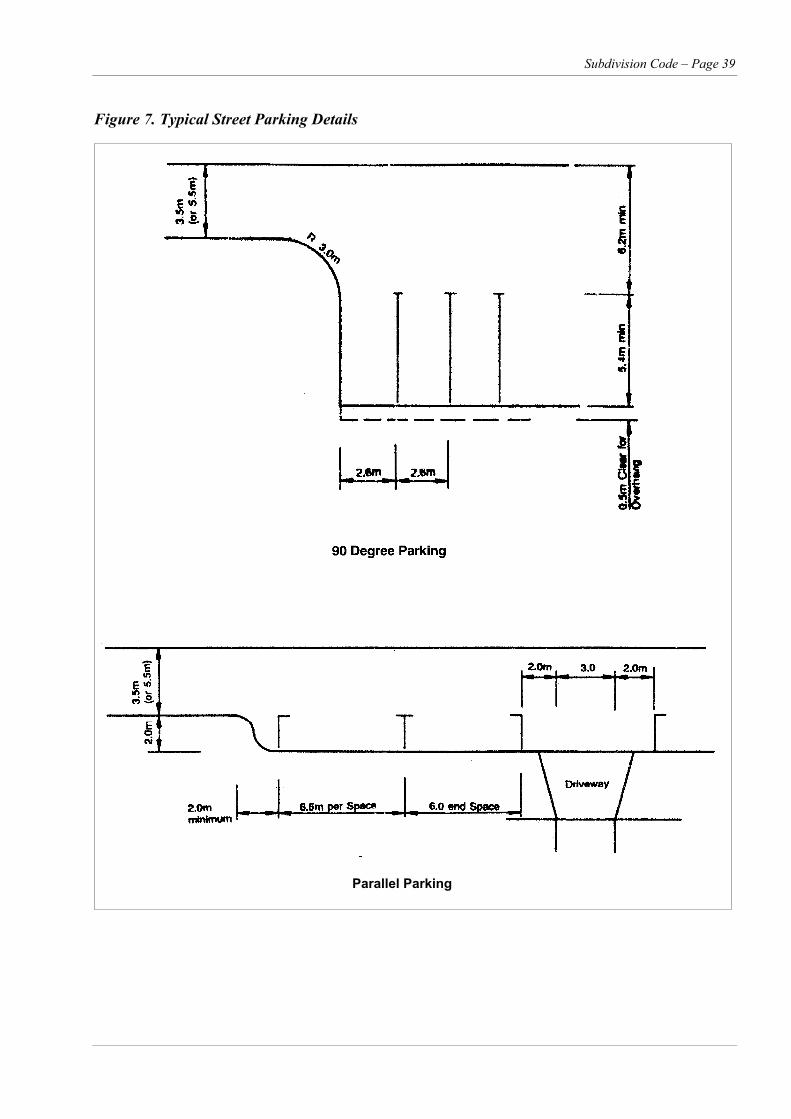
Subdivision Code – Page 39
Figure 7. Typical Street Parking Details
Parallel Parking
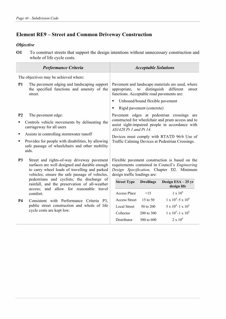
Page 40 – Subdivision Code
Element RE9 – Street and Common Driveway Construction
Objective O1 To construct streets that support the design intentions without unnecessary construction and
whole of life cycle costs.
Performance Criteria Acceptable Solutions
The objectives may be achieved where:
P1 The pavement edging and landscaping support the specified functions and amenity of the street.
Pavement and landscape materials are used, where appropriate, to distinguish different street functions. Acceptable road pavements are:
Unbound/bound flexible pavement
Rigid pavement (concrete)
P2 The pavement edge:
Controls vehicle movements by delineating the carriageway for all users
Assists in controlling stormwater runoff
Provides for people with disabilities, by allowing safe passage of wheelchairs and other mobility aids.
Pavement edges at pedestrian crossings are constructed for wheelchair and pram access and to assist sight-impaired people in accordance with AS1428 Pt 1 and Pt 14.
Devices must comply with RTATD 96/6 Use of Traffic Calming Devices at Pedestrian Crossings.
P3 Street and rights-of-way driveway pavement surfaces are well designed and durable enough to carry wheel loads of travelling and parked vehicles; ensure the safe passage of vehicles, pedestrians and cyclists; the discharge of rainfall, and the preservation of all-weather access; and allow for reasonable travel comfort.
P4 Consistent with Performance Criteria P3, public street construction and whole of life cycle costs are kept low.
Flexible pavement construction is based on the requirements contained in Council’s Engineering Design Specification, Chapter D2. Minimum design traffic loadings are:
Street Type Dwellings Design ESA – 25 yr design life
Access Place <15 1 x 10⁴
Access Street 15 to 50 1 x 10⁴–5 x 10⁴
Local Street 50 to 200 5 x 10⁴–1 x 10⁵
Collector 200 to 300 1 x 10⁵–1 x 10⁶
Distributor 300 to 600 2 x 10⁶
Subdivision Code – Page 41
Element RE9 – Street and Common Driveway Construction (cont’d)
Performance Criteria Acceptable Solutions
All newly created public roads having flexible pavements must be surfaced on an approved base designed in accordance with APRG Report No. 21 for pavements with a traffic volume up to 5 x 10⁵ ESA or AUSTROADS, A Guide to the Structural Design of Road Pavements where Traffic Volumes Exceed 5 x 10⁵ ESA. Pavements must be surfaced as follows:
i. Arterial roads AC
ii. Local distributor roads AC including industrial roads
iii. Local access roads serving AC allotments of up to 2000 m2 or concrete
iv. Carparks – AC or patterned concrete.
v. Accessways – patterned concrete or AC
Kerb and gutter profiles are to comply with the requirements contained in Table 3.
Miscellaneous – see below for details on infill and two lot subdivisions.
Page 42 – Subdivision Code
Other Considerations e. Where not more than two lots are to be created and this Code specifies the installation of an isolated section of kerb and gutter and/or other road construction, then provided that all weather access is available to the proposed lots, Council may require a cash contribution for the roadworks specified, and the work will be carried out in conjunction with other construction by Council in the road concerned.
Site Specific Requirements for Infill or Two Lot Subdivision a. Where proposed allotments have frontage to an
existing sealed road, the developer shall provide necessary road widening if required, kerb and gutter, and appropriately sealed shoulders with associated drainage fronting the newly created allotments. f. The access strips to battle axe lots are to be
constructed to the rear of the front lots in order to avoid dust nuisance to the owners of such lots. Care is to be taken to allow satisfactory width for service mains beside the access construction. The construction is to extend to the kerb line or bitumen seal in the road fronting the subdivision.
b. At intersections with existing roads, the new sealed pavement shall be bellmouthed and extended to meet the existing pavement or in the event that the existing road is not sealed, the new pavement shall extend 2 metres beyond the gutter line. Road shoulders may be required to be sealed on the existing road. Rights of way serving up to 6 allotments are to be provided with reinforced concrete of varying widths and as detailed in Council’s Engineering Design Specification, Chapter D1.
i. Single battle axe lot – two reinforced concrete strips centrally placed each 0.8m wide, 100mm thick on 75mm FCR AS72 fabric, 20mpa with full width footpath concrete cross over. c. Where proposed allotments have frontage to an
existing gravel or unformed road the developer will be required to provide any necessary road widening, plus kerb and gutter, half width sealed pavement and necessary drainage fronting the new lots.
ii. Two battle axe lots – reinforced concrete pavement 3m wide 100mm thick on 75mm FCR AS72 Fabric with 35mm topcover 20mpa concrete.
iii. An alternative for (ii) 3m wide hotmix sealed pavement 25mm thick on 200mm of compacted road base.
d. In addition, if there is a section of unformed road leading to the subdivision, the developer will be required to construct this section of unformed road to a minimum gravel standard. The minimum gravel standard is 200mm of compacted material as specified in Council’s Flexible Pavement Materials Specification C242. Where the access road to a new subdivision is considered by Council to be inadequate to carry the increased traffic generated by the subdivision, Council may apply a Section 94 Contribution prior to the issue of an approval.
g Vehicle kerb crossings are required at access points to battle axe lots to connect with access strip construction.
h. Rights of way serving 3 to 6 residential allotments are to be provided with reinforced concrete driveways of varying width and as detailed in Council’s Engineering Design Specification, Chapter D1.

Subdivision Code – Page 43
Element RE10 – utility services
Objective O1 To ensure that residential areas are adequately serviced with sewerage, water, fire fighting, electricity,
street lighting and communication services, in a timely, cost effective, coordinated and efficient manner that supports sustainable development practices.
Performance Criteria Acceptable Solutions
P1 Design and provision of utility services, including sewerage, water electricity, gas, street lighting, and communication services, are cost effective over their life cycle and incorporate provisions to minimise adverse environmental impact in the short and long term.
The design and provision of utility services conforms to the requirement of the relevant service authorities.
Refer to Other Considerations Section for details and Council’s Engineering Design Specification, chapters D10 and D11.
P2 Compatible public utility services are located in common trenching (where practical) in order to minimise the land required and the costs for underground services.
P3 Development occurs within locations where there is an adequate water supply for domestic and fire fighting purposes.
P4 Development is staged to ensure that each stage is fully serviced before a new area is released.
P5 Water supply and sewerage networks are accessible, easy to maintain, and cost effective based on life cycle costs.
P6 Adequate buffers are maintained between utilities and houses to protect residential amenity and health.
Page 44 – Subdivision Code
Other Considerations
Water Supply, Sewerage, Electricity General Water supply and sewerage reticulation where
located in urban areas will require the extension of the system to and through the subdivision.
Section 64 Contributions on a per lot basis for water and sewerage headworks will apply. Special Section 64 contributions may apply to certain areas in the City.
In urban areas where Council proposes to commence construction of a water supply and or sewerage system within two years of the issue of a construction certificate, it will be a requirement to provide reticulation mains within the subdivision. Council shall provide a written statement that construction work on the system is planned to commence within two years.
Where a water supply and/or sewerage reticulation extension is capable of servicing intervening unsubdividable land the cost of the extension will be borne by the present subdivider and recouped by Council by contributions from subsequent subdividers benefiting by that extension.
Payment is to be made to Council for the cost of a 20mm water service for each lot.
Dual Occupancy Where dual occupancy is proposed to be subdivided for Torrens title purposes a separate water service will be required. Each proposed lot is to be provided with a sewerage connection which may require the extension of the sewerage main and or the provision of a junction.
Certificate of Compliance (CC) Where a Development/subdivision approval is conditioned with the provision of water or sewerage, a CC is to be obtained from Shoalhaven Water specifying what conditions must be complied with before the plan of survey or approved building plans are released.
Design Water and/or sewerage designs are to be
undertaken by qualified and experienced consultants. Consultants are advised that other utility authorities must be consulted in the
preparation of design plans and the location of services in the footpath should conform with the requirements of Council’s Engineering Design Specification, Chapters D10 and D11.
Construction of Works The subdivider is required to engage a suitably
qualified consultant to supervise construction of the works.
The subdivider will be responsible for the cost of inspection of the works by Council.
Maintenance Bond A maintenance bond of 5% (minimum) of the cost
of the works is to be lodged with Council at the time of acceptance of these works by Council (practical completion). The maintenance period shall be 6 months (or 12 months in the case of mechanical installations). Any defects in the works within the maintenance period will be notified to the applicant. If these defects are not rectified to the satisfaction of the Shoalhaven Water Director within one month of the expiration of the maintenance period, the Council shall be at liberty to rectify these defects and apply the maintenance bond to the cost of this rectification. Any unexpended balance will be refunded to the subdivider.
Pegging of Lot Boundaries All necessary pegs must be in position
(temporary pegs will be accepted) before construction work on water and sewerage reticulation commences.
Land Matters The subdivider, when providing services, will
be required to provide at no cost to Council:-
suitable easements for water mains and sewer rising mains where required;
an agreed area of land for pumping stations;
easements or land for access to pumping stations;
easements for power to pumping stations where required.
Widths of easements will be determined for each subdivision by Shoalhaven Water.
Electricity Supply and other Services Policy The responsible authority for electricity supply
within the City of Shoalhaven is Integral Energy. The policy of both Integral Energy and the
Subdivision Code – Page 45
Shoalhaven City Council is for underground electricity supply within residential subdivision, except where major technical difficulties may be encountered, eg. where there is significant rock.
Some cases will require special consideration by the Integral Energy, who will make the final determination.
Consent Conditions and Construction The Council will state the development consent
condition for electricity supply in its determination. Integral Energy will state upon application its detailed requirements including cost of street lighting and the provision of necessary land or easements for cables, lines and/or pad-mounted substations and road crossings.
Procedure Prior to Release of Survey Plan All requirements of Integral Energy as to
easements etc are to be incorporated in the final survey plan and associated Section 88B Instrument. Evidence is required that Integral Energy's requirements have been met before a Subdivision Certificate can be issued and the release of the plan of survey effected.
Other Utility Services Gas – Where gas reticulation within a
subdivision is desired and is available, subdividers are advised to discuss the matter with Integral Energy.
Telephone – Where underground power is to be provided Council will require underground telephone service as a condition of development (subdivision) approval. The Developer/ Subdivider is to be responsible to satisfy Council when this condition has been met prior to issuing of the subdivision certificate.
Location of Utility Services Subdividers may be aware of standard positions
in footways for utility services as proposed by the Streets Opening Conferences of 1998.
Although Council recognises the desirability of such a standard (especially in new roads), Council does not adopt this standard due to the variability of factors affecting the location of utility services and the existence of many non-standard services in existing roads.
Subdividers and utility authorities are informed that in each case individual consideration of the location of utility services in footways is
required, although in new roads it could be expected that the locations would probably conform closely to the Streets Opening Conference Standard.
In some cases, existing services may need to be relocated and/or lowered, and such work will be at the Subdividers cost. All such detail is to be shown on road and drainage plans submitted for Council approval.
In some locations where there is significant rock and where the authorities concerned agree, the Council will permit electricity, gas and telephone services to share a common trench.
Staged Development of Subdivisions Provided the stages are of sufficient area to
provide a reasonable amount and continuity of subdivision construction, the general concept of staged development in subdivisions is acceptable.
Where a DCP under the EPA Act has been finalised by Council for an area of proposed subdivision, any application must be in conformity with that Plan.
Design Requirements Developers and designers are referred to
Council's Engineering Design Specification, chapters D10 and D11 and construction specifications for further detail.
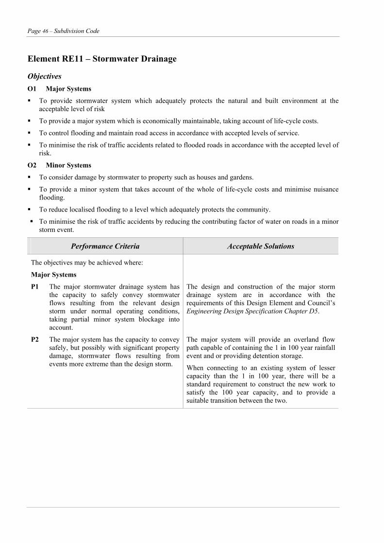
Page 46 – Subdivision Code
Element RE11 – Stormwater Drainage
Objectives O1 Major Systems
To provide stormwater system which adequately protects the natural and built environment at the acceptable level of risk
To provide a major system which is economically maintainable, taking account of life-cycle costs.
To control flooding and maintain road access in accordance with accepted levels of service.
To minimise the risk of traffic accidents related to flooded roads in accordance with the accepted level of risk.
O2 Minor Systems
To consider damage by stormwater to property such as houses and gardens.
To provide a minor system that takes account of the whole of life-cycle costs and minimise nuisance flooding.
To reduce localised flooding to a level which adequately protects the community.
To minimise the risk of traffic accidents by reducing the contributing factor of water on roads in a minor storm event.
Performance Criteria Acceptable Solutions
The objectives may be achieved where:
Major Systems
P1 The major stormwater drainage system has the capacity to safely convey stormwater flows resulting from the relevant design storm under normal operating conditions, taking partial minor system blockage into account.
The design and construction of the major storm drainage system are in accordance with the requirements of this Design Element and Council’s Engineering Design Specification Chapter D5.
P2 The major system has the capacity to convey safely, but possibly with significant property damage, stormwater flows resulting from events more extreme than the design storm.
The major system will provide an overland flow path capable of containing the 1 in 100 year rainfall event and or providing detention storage.
When connecting to an existing system of lesser capacity than the 1 in 100 year, there will be a standard requirement to construct the new work to satisfy the 100 year capacity, and to provide a suitable transition between the two.
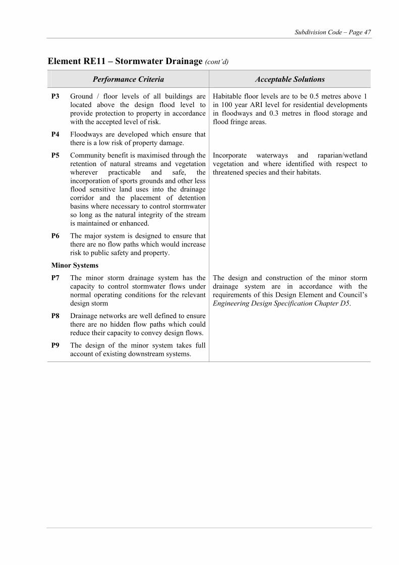
Subdivision Code – Page 47
Element RE11 – Stormwater Drainage (cont’d)
Performance Criteria Acceptable Solutions
P3 Ground / floor levels of all buildings are located above the design flood level to provide protection to property in accordance with the accepted level of risk.
Habitable floor levels are to be 0.5 metres above 1 in 100 year ARI level for residential developments in floodways and 0.3 metres in flood storage and flood fringe areas.
P4 Floodways are developed which ensure that there is a low risk of property damage.
P5 Community benefit is maximised through the retention of natural streams and vegetation wherever practicable and safe, the incorporation of sports grounds and other less flood sensitive land uses into the drainage corridor and the placement of detention basins where necessary to control stormwater so long as the natural integrity of the stream is maintained or enhanced.
Incorporate waterways and raparian/wetland vegetation and where identified with respect to threatened species and their habitats.
P6 The major system is designed to ensure that there are no flow paths which would increase risk to public safety and property.
Minor Systems
P7 The minor storm drainage system has the capacity to control stormwater flows under normal operating conditions for the relevant design storm
The design and construction of the minor storm drainage system are in accordance with the requirements of this Design Element and Council’s Engineering Design Specification Chapter D5.
P8 Drainage networks are well defined to ensure there are no hidden flow paths which could reduce their capacity to convey design flows.
P9 The design of the minor system takes full account of existing downstream systems.
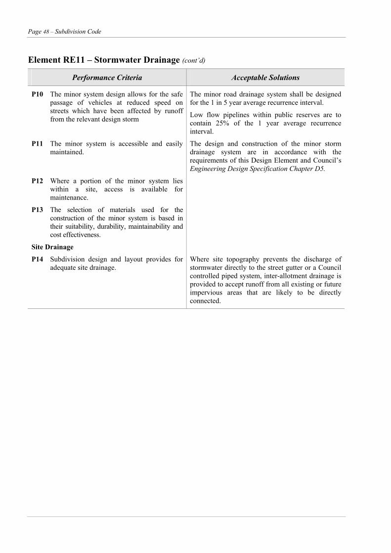
Page 48 – Subdivision Code
Element RE11 – Stormwater Drainage (cont’d)
Performance Criteria Acceptable Solutions
P10 The minor system design allows for the safe passage of vehicles at reduced speed on streets which have been affected by runoff from the relevant design storm
The minor road drainage system shall be designed for the 1 in 5 year average recurrence interval.
Low flow pipelines within public reserves are to contain 25% of the 1 year average recurrence interval.
P11 The minor system is accessible and easily maintained.
The design and construction of the minor storm drainage system are in accordance with the requirements of this Design Element and Council’s Engineering Design Specification Chapter D5.
P12 Where a portion of the minor system lies within a site, access is available for maintenance.
P13 The selection of materials used for the construction of the minor system is based in their suitability, durability, maintainability and cost effectiveness.
Site Drainage
P14 Subdivision design and layout provides for adequate site drainage.
Where site topography prevents the discharge of stormwater directly to the street gutter or a Council controlled piped system, inter-allotment drainage is provided to accept runoff from all existing or future impervious areas that are likely to be directly connected.
Subdivision Code – Page 49
Other Considerations Where a piped system exists in close proximity to the development, connection to that system shall be required.
Drainage Where the calculated stormwater discharge exceeds the capacity of two 100mm pipes, then discharge into the kerb and gutter may be provided by means of a concrete converter.
Floor Levels
Floor levels of all habitual rooms shall be 300 mm above the 1 in 100 year Average Recurrence Interval in flood storage areas and 500mm in floodways. Such minimum floor levels shall be specified, adjacent to drainage paths, on subdivision and engineering plans. This shall include roads where they are used as overflow paths in the major/minor design concept.
The maximum discharge allowable by this method is 55l/sec. Construction to be in accordance with Standard Plan Drawing Plan Ref 263726.
Where the total discharge from any Development/ Subdivision exceeds 55 l/sec, the disposal of all concentrated/paved surface runoff and roof discharge shall be by means of a drainage line connected directly into an existing Council pipeline or stormwater channel.
Bridges
All bridges are to be designed for a 1 in 100 year Average Recurrence Interval. The design is to be checked for effect of probable maximum flood level. Where, however, the approach road but excluding bridge approaches has a flood level below the 1:100 year level then a lower standard of level may be acceptable.
Where however the approach road but excluding bridge approaches has a flood level below the 1:100 year level then a lower standard of level may be acceptable.
Small bridges and culverts within rights of way shall be designed with appropriate afflux to the 1:5 ARI event. Certification is to be provided stating the bridge can withstand loadings up to the 1:100 year storm event. Waterways Design to be in accordance with Austroads A Guide to the Hydraulic Design of Bridges, Culverts and Floodways.
Small bridges and culverts within rights-of-way shall be designed with appropriate afflux to the 1:5 ARI event. Certification is to be provided stating the bridge can withstand loadings of up to the 1:100 year storm event. Waterway Design to be in accordance with Austroads A guide to the Hydraulic Design of Bridges, Culverts and Floodways. Interallotment Drainage
Design requirements are provided in Council’s Engineering Design Specification, chapter D3.
Interallotment drainage lines are to be at least 0.5 metres from the lot boundary and contained within a drainage easement of minimum width 1.0 metres. Detention Basins Interallotment drainage is to be provided for every allotment which does not drain directly to its street frontage or a natural watercourse. Easements shall be in favour of the benefiting allotments. Council is not responsible for the maintenance and control of interallotment drainage lines. Drainage pits are to be located at all changes of direction and at a maximum spacing of 60 metres.
Where down stream storm water drainage systems are inadequate and the cost of upgrading is excessive, Council may determine the use of a detention basin as being applicable.
The design should be based on the 1 in 100 Average Recurrence Interval storm. Full design criteria is available in Council's Engineering Design Specification Chapter D5.
Easements Flood Studies Necessary road drainage easements – minimum of 3
metres width; see full drainage easement width requirements in the Engineering Design Specification Chapter D5 – are to be provided free of cost to Council. Easements are to be piped. Pathways may be used in lieu of an easement where appropriate.
Developments/subdivisions which are within flood prone areas, or which may be subject to temporary local flooding, shall require a flood level analysis to be prepared by a civil engineer of NPER standing or equivalent qualifications and experience.
Drainage Discharge from Property Development
Where the stormwater drainage conveyed in a drainage easement discharge onto land other than an existing drainage easement or public place, it shall be the responsibility of the developer/ subdivider to obtain a drainage easement through such land, sufficient in dimensions to drain, including overflow, to an existing easement, natural watercourse or public place and to transfer easement rights to Council.
All drainage lines emanating from property developments must have a point of discharge approved by Council. Drainage from a development can be discharged into the kerb and gutter by two 100mm dia pipes where the calculated flow does not exceed the pipes capacity.

Page 50 – Subdivision Code
Element RE12 – Stormwater Quality Management
Objectives O1 To ensure that existing downstream systems are not adversely affected and ensure no net increase in
pollution levels discharging from the development.
O2 The interception and treatment of pollutants through the use of appropriate water quality control measures prior to discharge to receiving waters, including wetlands, lakes and ponds.
O3 The drainage system optimises control of any accumulation of silts and controls blockages by debris of inlet structures and pipes.
O4 The design and construction of water quality control facilities will be undertaken to the requirements of Council and relevant authorities.
Performance Criteria Acceptable Solutions
The objectives may be achieved where:
P1 Adequate provision is made for measures during construction to ensure that the land form is stabilised and erosion is controlled.
An Erosion and Sediment Management Plan is prepared by suitably qualified personnel using recognised and locally accepted hydrological, hydraulic hydrogeological, soils, water quality and biological data and design methodologies.
P2 The system design optimises the interception, retention and removal of water-borne pollutants through the use of appropriate criteria, prior to their discharge to receiving waters.
The Erosion and Sediment Management Plan is to comply with Council’s Engineering Design Specifications, Chapter D7 and Environmental Protection Authority Manual.
P3 The system design minimises the environmental impact of urban runoff on surface receiving water quality and on other aspects of the natural environment, such as creek configuration and existing vegetation, by employing techniques which are appropriate and effective in reducing runoff and pollution travel.
P4 Sewerage overflows into the stormwater system are prevented.
Water pollution control ponds or wetlands are developed (where appropriate) for final treatment before discharge to the wider environment and should be sited to minimise impacts on the natural environment. See Figure 8 and Council’s Engineering Design Specifications, Chapter D7. All pollution control mechanisms are to be in accordance with the Department of Housing’s “Managing Urban Stormwater Soils and Construction” manual.
P5 Point sources of pollution in the catchment should be identified and their impact minimised until their impact can be eliminated.
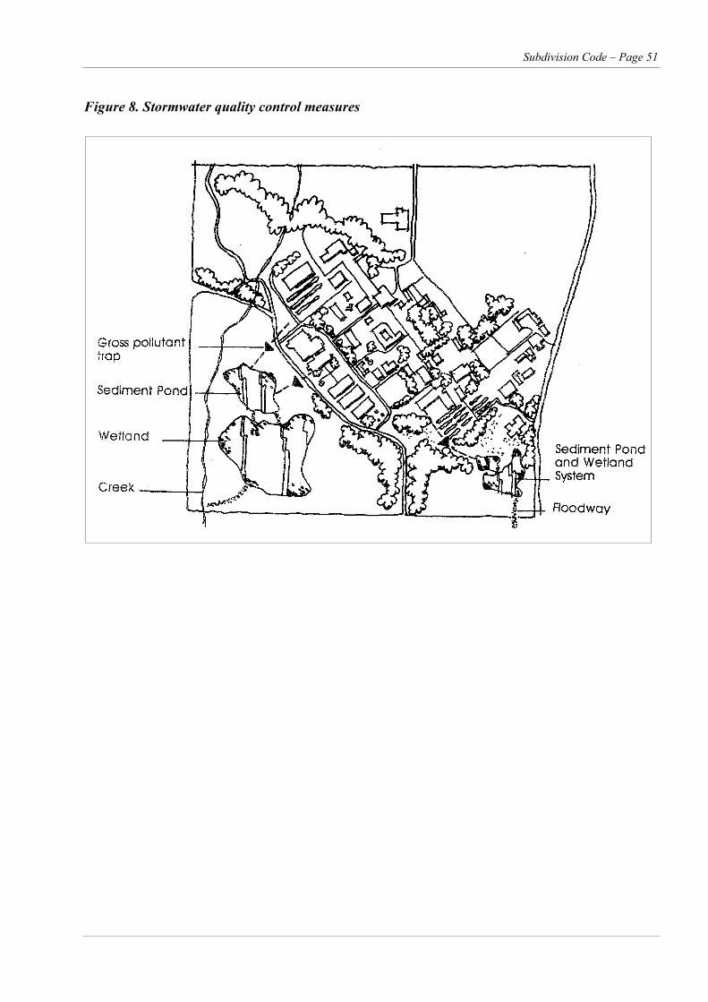
Subdivision Code – Page 51
Figure 8. Stormwater quality control measures
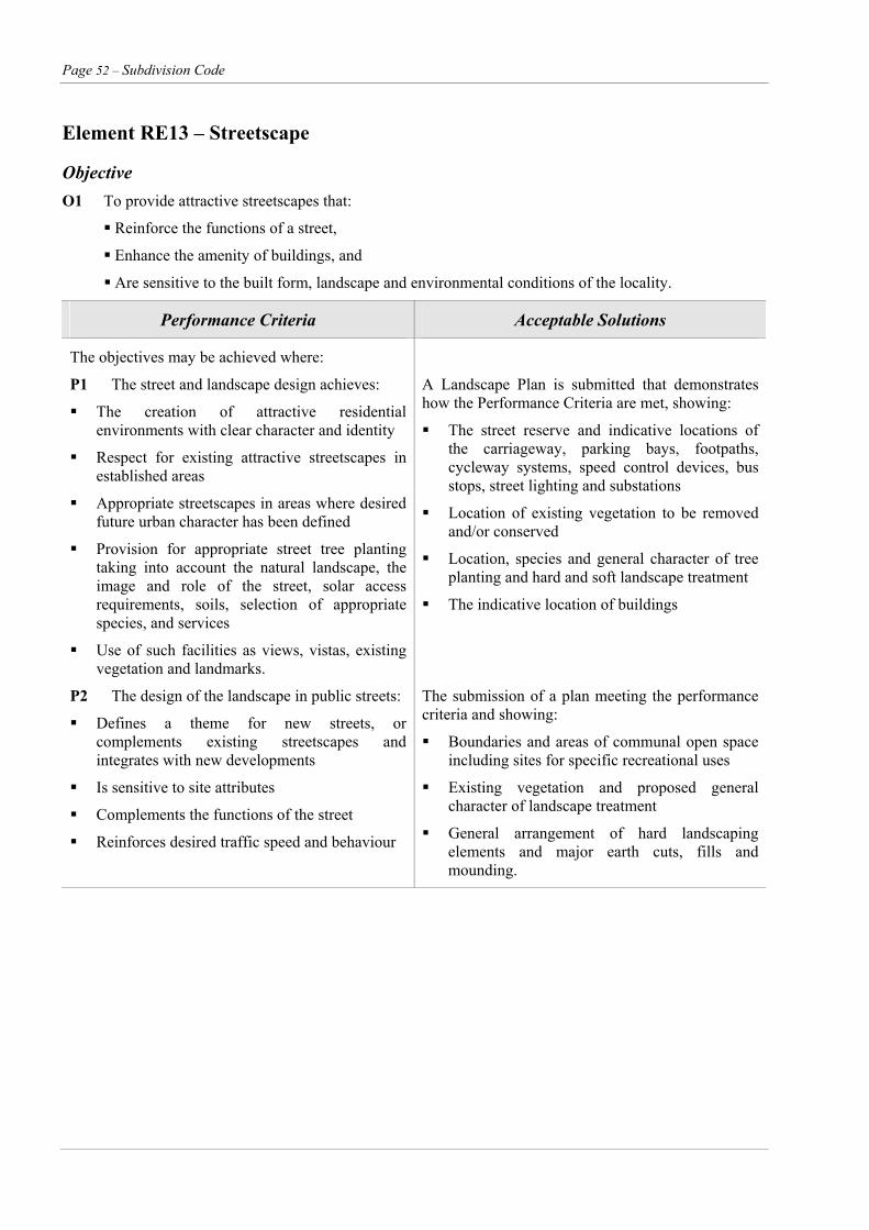
Page 52 – Subdivision Code
Element RE13 – Streetscape
Objective O1 To provide attractive streetscapes that:
Reinforce the functions of a street,
Enhance the amenity of buildings, and
Are sensitive to the built form, landscape and environmental conditions of the locality.
Performance Criteria Acceptable Solutions
The objectives may be achieved where:
P1 The street and landscape design achieves:
The creation of attractive residential environments with clear character and identity
Respect for existing attractive streetscapes in established areas
Appropriate streetscapes in areas where desired future urban character has been defined
Provision for appropriate street tree planting taking into account the natural landscape, the image and role of the street, solar access requirements, soils, selection of appropriate species, and services
Use of such facilities as views, vistas, existing vegetation and landmarks.
A Landscape Plan is submitted that demonstrates how the Performance Criteria are met, showing:
The street reserve and indicative locations of the carriageway, parking bays, footpaths, cycleway systems, speed control devices, bus stops, street lighting and substations
Location of existing vegetation to be removed and/or conserved
Location, species and general character of tree planting and hard and soft landscape treatment
The indicative location of buildings
P2 The design of the landscape in public streets:
Defines a theme for new streets, or complements existing streetscapes and integrates with new developments
Is sensitive to site attributes
Complements the functions of the street
Reinforces desired traffic speed and behaviour
The submission of a plan meeting the performance criteria and showing:
Boundaries and areas of communal open space including sites for specific recreational uses
Existing vegetation and proposed general character of landscape treatment
General arrangement of hard landscaping elements and major earth cuts, fills and mounding.

Subdivision Code – Page 53
Element RE13 – Streetscape (cont’d)
Performance Criteria Acceptable Solutions
P2 (cont’d)
Is of an appropriate scale relative to both the street reserve width and existing or expected future building bulk
Promotes safety and casual street surveillance
Improves privacy and minimises unwanted overlooking
Incorporates existing vegetation where possible and desirable
Promotes the planting of native vegetation in environmentally sensitive areas
Appropriately accounts for streetscapes and landscapes of heritage significance
Assists in microclimate management
Maximises landscaped areas where appropriate
Integrates and forms linkages with parks, reserves and transport corridors
Enhances opportunities for pedestrian comfort
Achieves lines of sight for pedestrians, cyclists and vehicles
Provides adequate lighting for pedestrian and vehicle safety
Provides attractive and coordinated street furniture and facilities to meet user needs
Satisfies maintenance and utility requirements and minimises their visual impact of above ground utilities.
Landscaping of floodways, drainage lines, type of fencing, threshold treatment entrance statement.
Footpath trees maximum spacing 10 metres, minimum of two trees per lot, minimum distance from intersection 10 metres, provide a six month maintenance period.
Common design theme that aids street identity, lighting, signs, tree guards, bus shelters. Street signs to be placed at all intersections in accordance with AS1743 Road Signs.
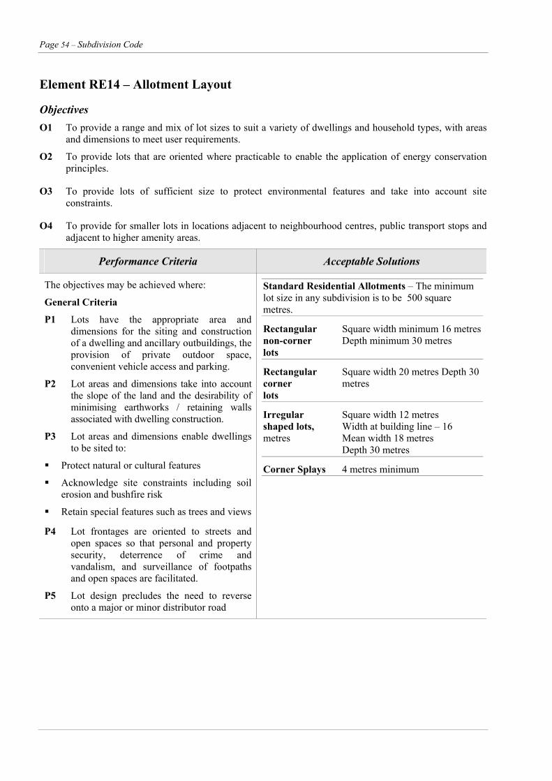
Page 54 – Subdivision Code
Element RE14 – Allotment Layout
Objectives O1 To provide a range and mix of lot sizes to suit a variety of dwellings and household types, with areas
and dimensions to meet user requirements.
O2 To provide lots that are oriented where practicable to enable the application of energy conservation principles.
O3 To provide lots of sufficient size to protect environmental features and take into account site constraints.
O4 To provide for smaller lots in locations adjacent to neighbourhood centres, public transport stops and adjacent to higher amenity areas.
Performance Criteria Acceptable Solutions
The objectives may be achieved where:
General Criteria
P1 Lots have the appropriate area and dimensions for the siting and construction of a dwelling and ancillary outbuildings, the provision of private outdoor space, convenient vehicle access and parking.
P2 Lot areas and dimensions take into account the slope of the land and the desirability of minimising earthworks / retaining walls associated with dwelling construction.
P3 Lot areas and dimensions enable dwellings to be sited to:
Protect natural or cultural features
Acknowledge site constraints including soil erosion and bushfire risk
Retain special features such as trees and views
Standard Residential Allotments – The minimum lot size in any subdivision is to be 500 square metres.
Rectangular Square width minimum 16 metresnon-corner Depth minimum 30 metres lots
Rectangular Square width 20 metres Depth 30corner metres lots
Irregular Square width 12 metres shaped lots, Width at building line – 16 metres Mean width 18 metres Depth 30 metres
Corner Splays 4 metres minimum
P4 Lot frontages are oriented to streets and open spaces so that personal and property security, deterrence of crime and vandalism, and surveillance of footpaths and open spaces are facilitated.
P5 Lot design precludes the need to reverse onto a major or minor distributor road
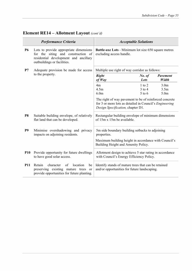
Subdivision Code – Page 55
Element RE14 – Allotment Layout (cont’d)
Performance Criteria Acceptable Solutions
P6 Lots to provide appropriate dimensions for the siting and construction of residential development and ancillary outbuildings or facilities.
Battle-axe Lots - Minimum lot size 650 square metres excluding access handle.
P7 Adequate provision be made for access to the property.
Multiple use right of way corridor as follows: Right No. of Pavement of Way Lots Width 4m 1 to 2 3.0m 4.5m 3 to 4 3.5m 6.0m 5 to 6 5.0m
The right of way pavement to be of reinforced concrete for 3 or more lots as detailed in Council’s Engineering Design Specification, chapter D1.
P8 Suitable building envelope, of relatively flat land that can be developed.
Rectangular building envelope of minimum dimensions of 15m x 15m be available.
P9 Minimise overshadowing and privacy impacts on adjoining residents.
5m side boundary building setbacks to adjoining properties.
Maximum building height in accordance with Council’s Building Height and Amenity Policy.
P10 Provide opportunity for future dwellings to have good solar access.
Allotment design to achieve 5 star rating in accordance with Council’s Energy Efficiency Policy.
P11 Retain character of location be preserving existing mature trees or provide opportunities for future planting.
Identify stands of mature trees that can be retained and/or opportunities for future landscaping.

Page 56 – Subdivision Code
Element RE14 – Allotment Layout (cont’d)
Performance Criteria Acceptable Solutions
P12 Density Lot areas should conform with minimum requirements as setout in relevant zones detailed in SLEP1985. Small lot subdivision (below standard allotment requirements) shall only be located in accordance with Council’s adopted housing strategy or DCP. That is, within a locality clearly identified as suitable for such development.
P13 Allotment Design Considerations The following matters should be
addressed in the allotment design: Building envelope – setbacks, building to boundary areas, height, floor levels, northern boundary setback for solar access. Building details – frontage orientation, privacy, street surveillance and window location, screening, style elements, roof form, colours and materials. Parking – number of spaces, locations, access. Private Open Space – location, dimensions, qualities. Fencing – heights, materials, detailing, retaining walls. Services – easements, stormwater, air conditioners. Landscaping – protection of existing streets, space for shade trees. Noise – buffering – dwelling design and layout to protect from external noise, provision of noise-buffering walls. Storage space – potential location and size. Energy efficiency – window location, shading, shared boundary walls. Setting on lot in relation to shape – retaining walls cut and fill. Encroachments – porches and verandahs, utilities, reciprocal right-of-way, party walls.
P14 Integrated or medium density lots shall only be located in medium density zones as defined in Council’s SLEP1985.
Small Minimum 350m2. Residential Minimum frontage 15m Allotments Battle-axe lots to be 25% greater in area than adjoining lots including access handles
Detailed Area The applicant provides detailed area Plans for plans (DAP) which include: Small Lots Parking and Access provide two spaces per dwelling within the allotment, one of which may be in tandem. specify the vehicle access point in
a manner that optimises on-street parking, where a lane is provided parking must be accessed from it.
specify the garage location and size and ensure it is set back behind the frontage of the dwelling.
Building envelope and windows specify the minimum frontage
setback and maximum building height, building to boundary locations and wall heights, and other side and rear setbacks, eg relating to solar access, tree protection easements.
specify any critical window locations and treatment, eg for solar access, shading, frontage outlook or limit overlooking or noise intrusions.
Private open space and fencing ensure that a minimum private
outdoor area of 60m2 with minimum dimension of 5m, will be provided at the side or rear of the dwellings.
limit front fence height to a maximum of 1m if solid and to 1.5m if more than 50% transparent.
Integrated or Compliance with Council’s Medium Medium Density guidelines Density Allotments
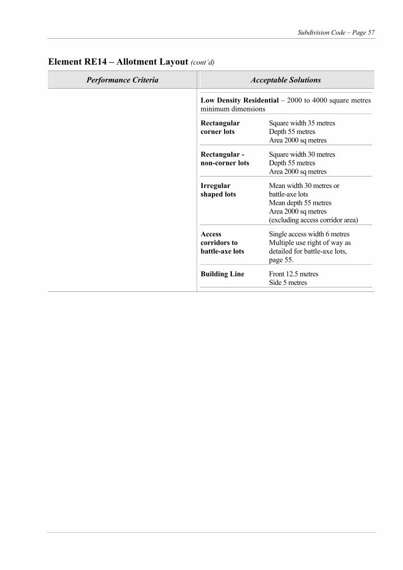
Subdivision Code – Page 57
Element RE14 – Allotment Layout (cont’d)
Performance Criteria Acceptable Solutions
Low Density Residential – 2000 to 4000 square metres minimum dimensions
Rectangular Square width 35 metres corner lots Depth 55 metres Area 2000 sq metres
Rectangular - Square width 30 metres non-corner lots Depth 55 metres Area 2000 sq metres
Irregular Mean width 30 metres or shaped lots battle-axe lots Mean depth 55 metres Area 2000 sq metres (excluding access corridor area)
Access Single access width 6 metres corridors to Multiple use right of way as battle-axe lots detailed for battle-axe lots, page 55.
Building Line Front 12.5 metres Side 5 metres
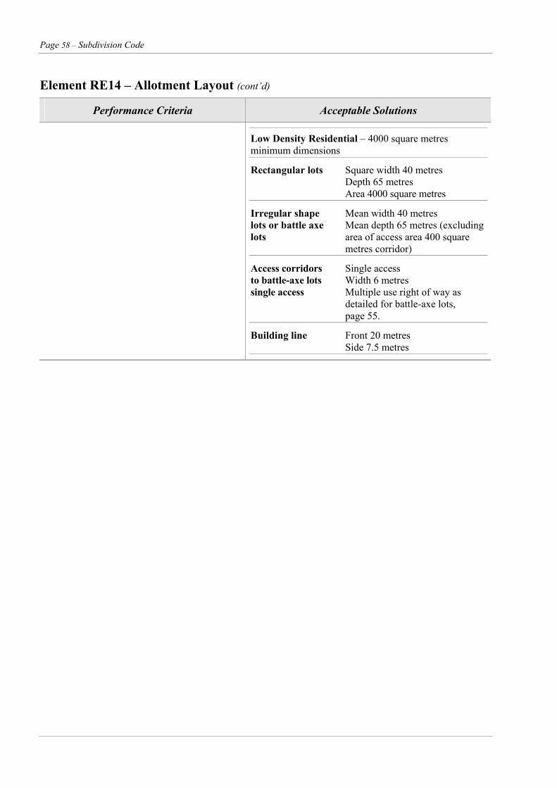
Page 58 – Subdivision Code
Element RE14 – Allotment Layout (cont’d)
Performance Criteria Acceptable Solutions
Low Density Residential – 4000 square metres minimum dimensions
Rectangular lots Square width 40 metres Depth 65 metres Area 4000 square metres
Irregular shape Mean width 40 metres lots or battle axe Mean depth 65 metres (excluding lots area of access area 400 square metres corridor)
Access corridors Single access to battle-axe lots Width 6 metres single access Multiple use right of way as detailed for battle-axe lots, page 55.
Building line Front 20 metres Side 7.5 metres
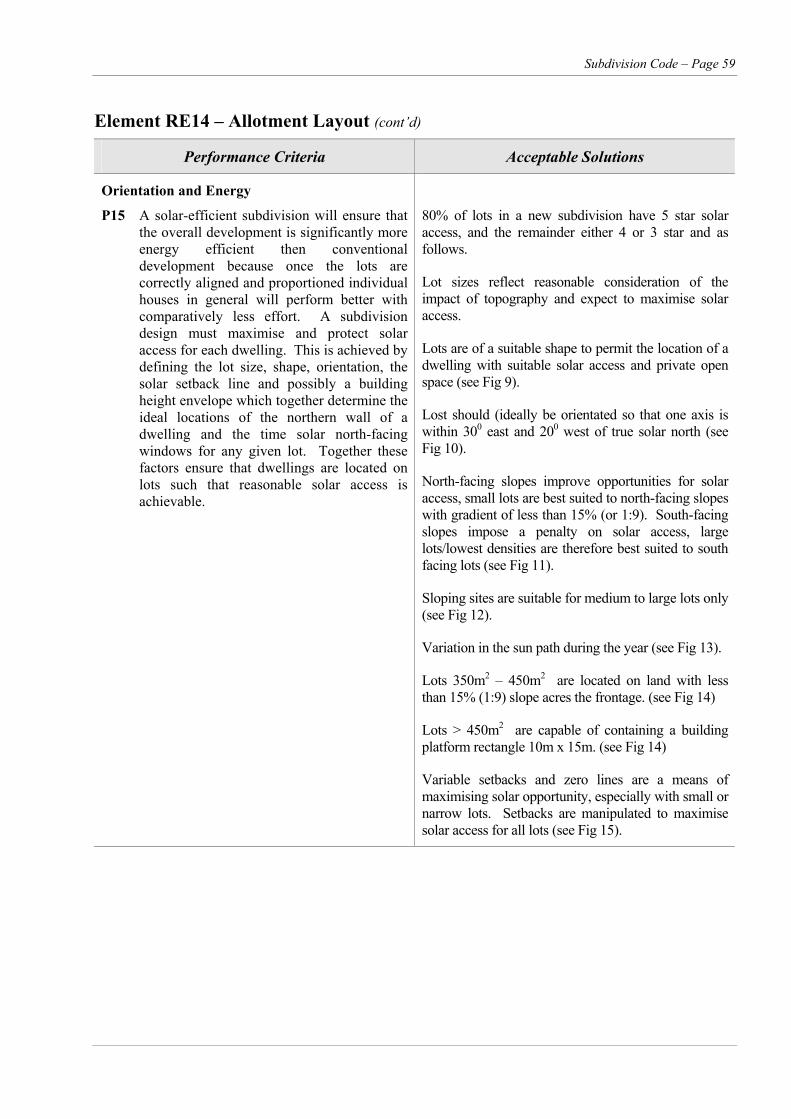
Subdivision Code – Page 59
Element RE14 – Allotment Layout (cont’d)
Performance Criteria Acceptable Solutions
Orientation and Energy
P15 A solar-efficient subdivision will ensure that the overall development is significantly more energy efficient then conventional development because once the lots are correctly aligned and proportioned individual houses in general will perform better with comparatively less effort. A subdivision design must maximise and protect solar access for each dwelling. This is achieved by defining the lot size, shape, orientation, the solar setback line and possibly a building height envelope which together determine the ideal locations of the northern wall of a dwelling and the time solar north-facing windows for any given lot. Together these factors ensure that dwellings are located on lots such that reasonable solar access is achievable.
80% of lots in a new subdivision have 5 star solar access, and the remainder either 4 or 3 star and as follows.
Lot sizes reflect reasonable consideration of the impact of topography and expect to maximise solar access.
Lots are of a suitable shape to permit the location of a dwelling with suitable solar access and private open space (see Fig 9).
Lost should (ideally be orientated so that one axis is within 300 east and 200 west of true solar north (see Fig 10).
North-facing slopes improve opportunities for solar access, small lots are best suited to north-facing slopes with gradient of less than 15% (or 1:9). South-facing slopes impose a penalty on solar access, large lots/lowest densities are therefore best suited to south facing lots (see Fig 11).
Sloping sites are suitable for medium to large lots only (see Fig 12).
Variation in the sun path during the year (see Fig 13).
Lots 350m2 – 450m2 are located on land with less than 15% (1:9) slope acres the frontage. (see Fig 14)
Lots > 450m2 are capable of containing a building platform rectangle 10m x 15m. (see Fig 14)
Variable setbacks and zero lines are a means of maximising solar opportunity, especially with small or narrow lots. Setbacks are manipulated to maximise solar access for all lots (see Fig 15).
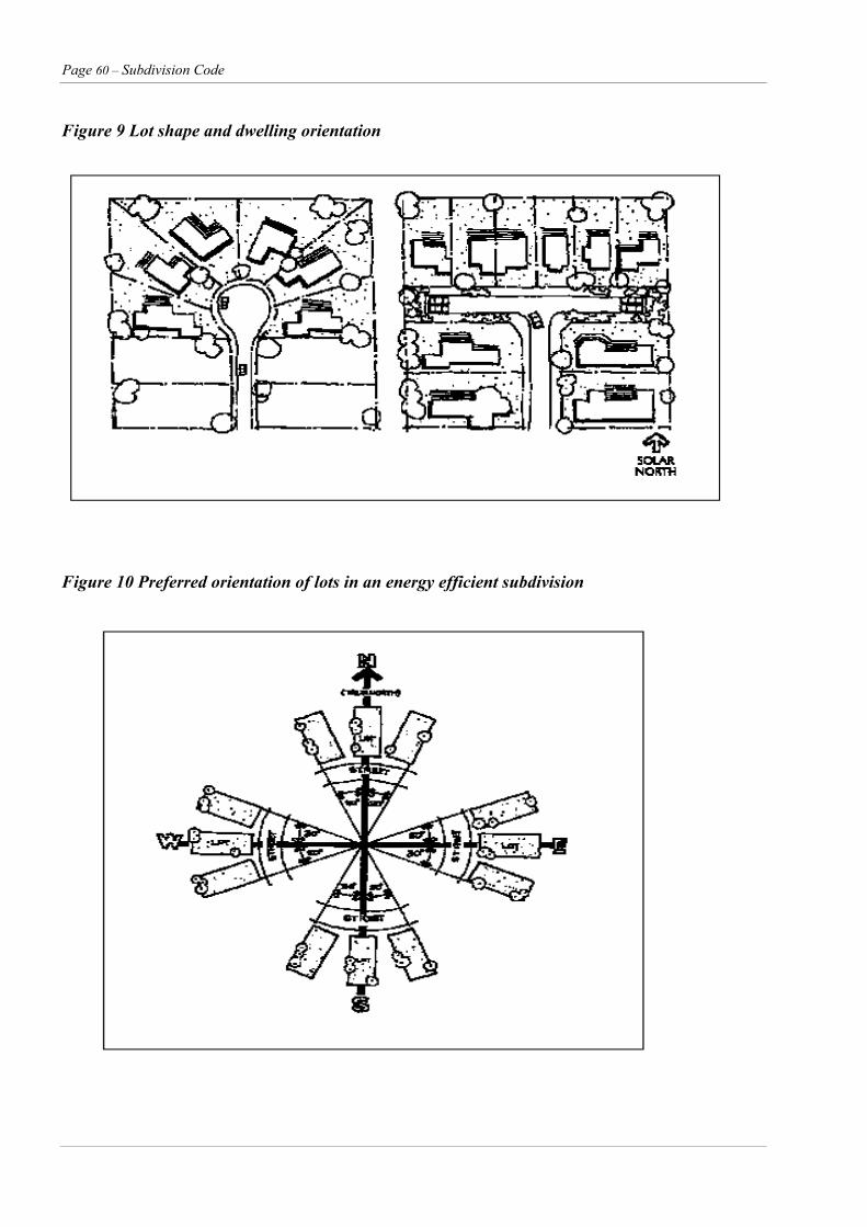
Page 60 – Subdivision Code
Figure 9 Lot shape and dwelling orientation
Figure 10 Preferred orientation of lots in an energy efficient subdivision
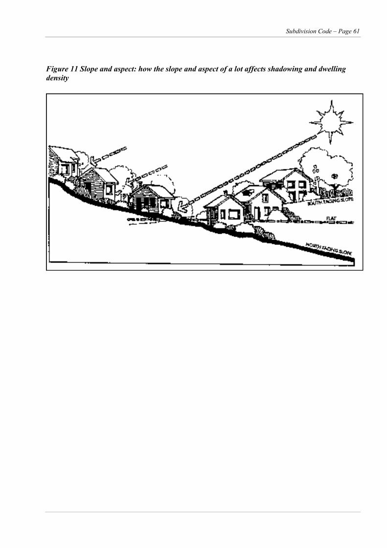
Subdivision Code – Page 61
Figure 11 Slope and aspect: how the slope and aspect of a lot affects shadowing and dwelling density
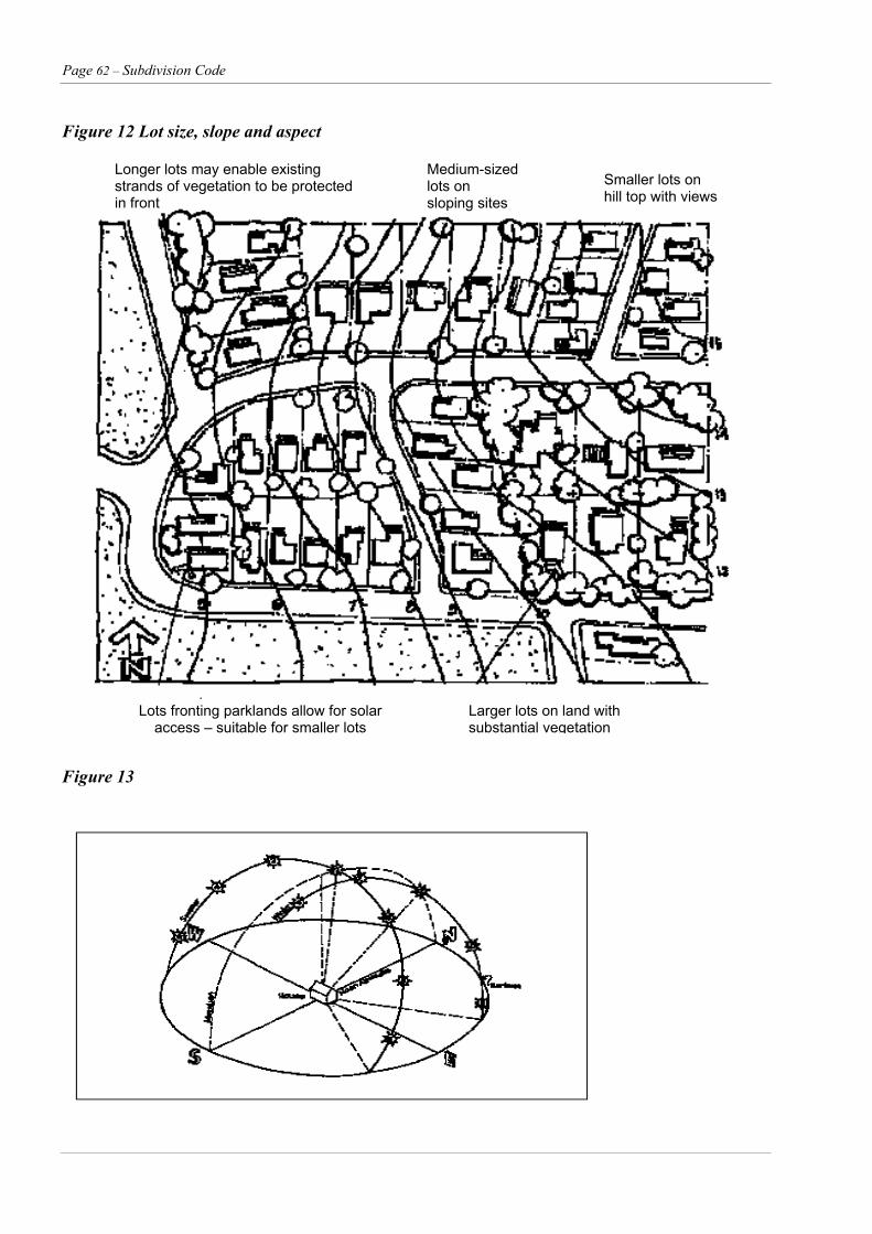
Page 62 – Subdivision Code
Figure 12 Lot size, slope and aspect
Longer lots may enable existing strands of vegetation to be protected in front
Medium-sized lots on sloping sites
Smaller lots on hill top with views
Lots fronting parklands allow for solar access – suitable for smaller lots
Figure 13
Larger lots on land with substantial vegetation
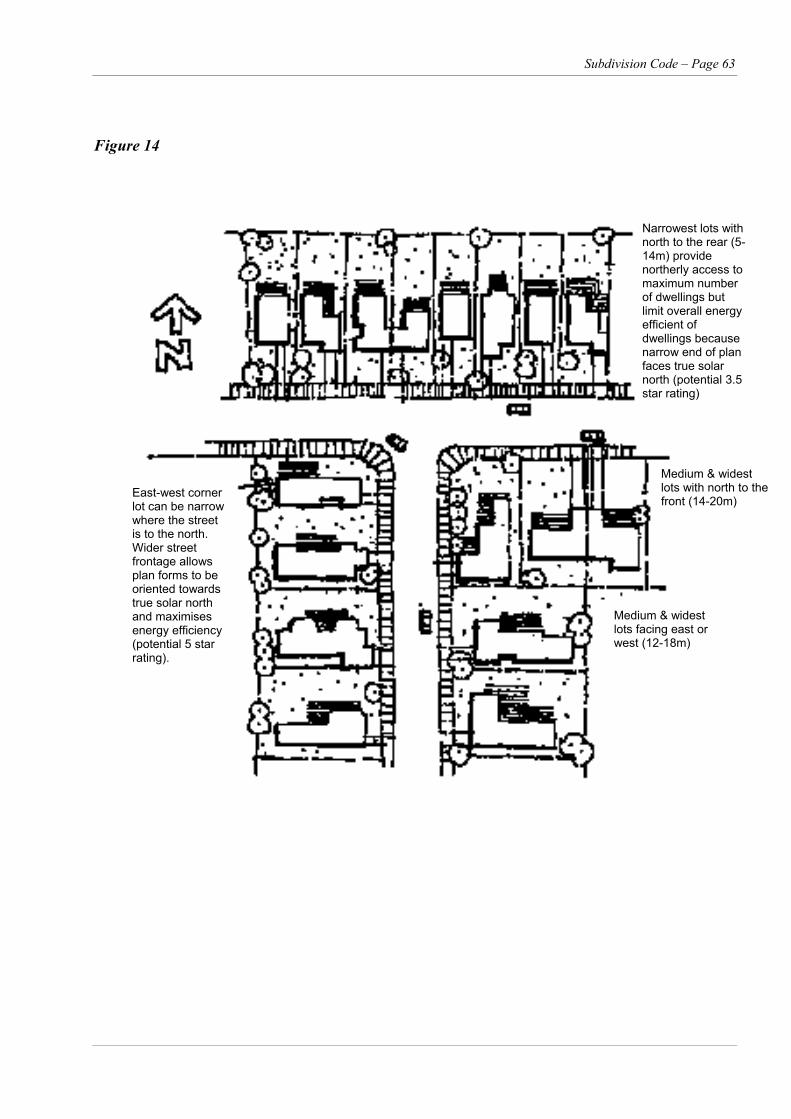
Subdivision Code – Page 63
Figure 14
Narrowest lots with north to the rear (5-14m) provide northerly access to maximum number of dwellings but limit overall energy efficient of dwellings because narrow end of plan faces true solar north (potential 3.5 star rating)
Medium & widest lots with north to the front (14-20m)
East-west corner lot can be narrow where the street is to the north. Wider street frontage allows plan forms to be oriented towards true solar north and maximises energy efficiency (potential 5 star rating).
Medium & widest lots facing east or west (12-18m)
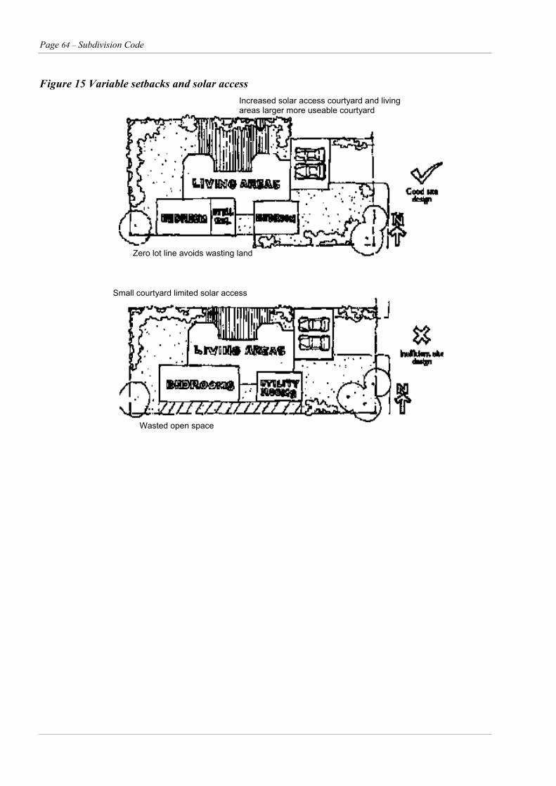
Page 64 – Subdivision Code
Figure 15 Variable setbacks and solar access
Increased solar access courtyard and living areas larger more useable courtyard
Zero lot line avoids wasting land
Small courtyard limited solar access
Wasted open space
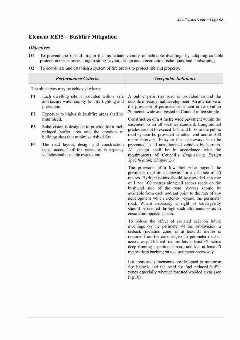
Subdivision Code – Page 65
Element RE15 – Bushfire Mitigation
Objectives O1 To prevent the risk of fire in the immediate vicinity of habitable dwellings by adopting suitable
protection measures relating to siting, layout, design and construction techniques, and landscaping.
O2 To coordinate and establish a system of fire breaks to protect life and property.
Performance Criteria Acceptable Solutions
The objectives may be achieved where:
P1 Each dwelling site is provided with a safe and secure water supply for fire fighting and protection.
P2 Exposure to high-risk bushfire areas shall be minimised.
P3 Subdivision is designed to provide for a fuel-reduced buffer area and the creation of building sites that minimise risk of fire.
P4 The road layout, design and construction takes account of the needs of emergency vehicles and possible evacuation.
A public perimeter road is provided around the outside of residential development. An alternative is the provision of perimeter easement or reservation 20 metres wide and vested in Council in fee simple.
Construction of a 4 metre wide pavement within the easement to an all weather standard. Longitudinal grades are not to exceed 15% and links to the public road system be provided at either end and at 300 metre intervals. Entry to the accessways is to be prevented to all unauthorised vehicles by barriers. All design shall be in accordance with the requirements of Council’s Engineering Design Specification, Chapter D9.
The provision of a low fuel zone beyond the perimeter road or accessway for a distance of 40 metres. Hydrant points should be provided at a rate of 1 per 100 metres along all access roads on the bushland side of the road. Access should be available from each hydrant point to the rear of any development which extends beyond the perimeter road. Where necessary a right of carriageway should be created through such allotments so as to ensure unimpeded access.
To reduce the effect of radiated heat on future dwellings on the perimeter of the subdivision, a setback (radiation zone) of at least 35 metres is required from the outer edge of a perimeter road or access way. This will require lots at least 35 metres deep fronting a perimeter road, and lots at least 40 metres deep backing on to a perimeter accessway.
Lot areas and dimensions are designed to minimise fire hazards and the need for fuel reduced buffer zones especially whether forested/wooded areas (see Fig 16).
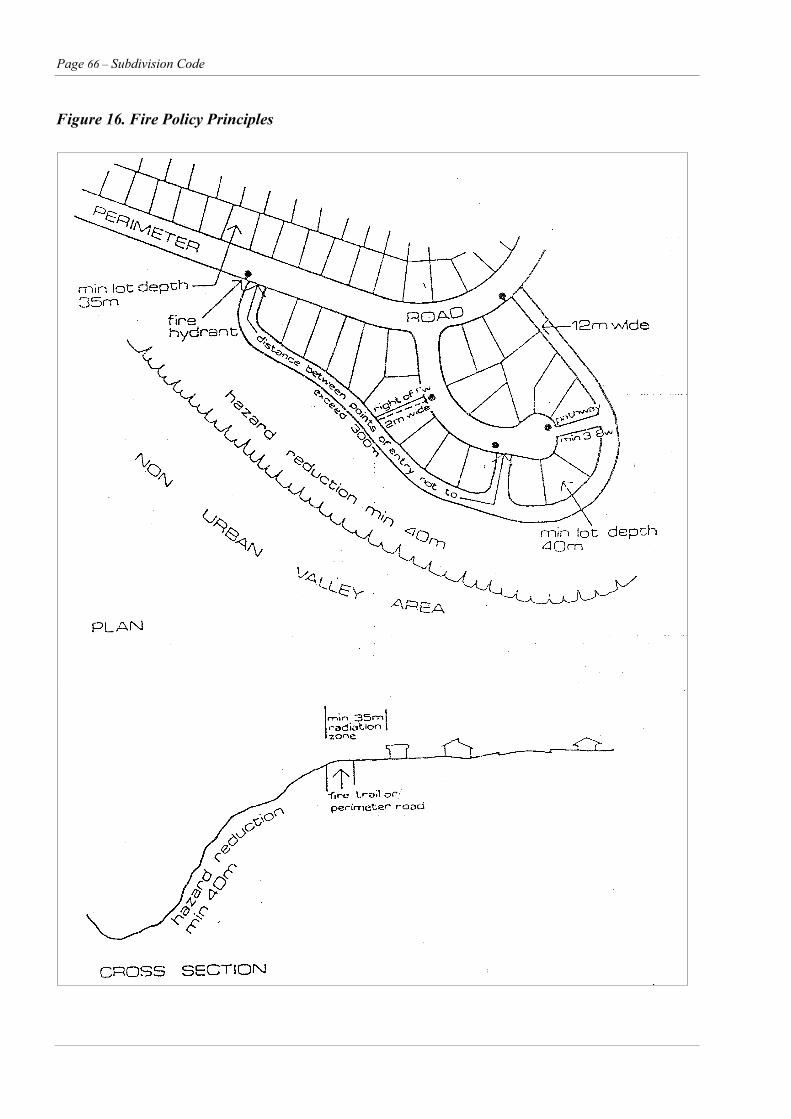
Page 66 – Subdivision Code
Figure 16. Fire Policy Principles
Subdivision Code – Page 67
Element RE16 – Geotechnical
Objective O1 To ensure efficient and economical subdivision design which will have minimal impact on adjoining
properties and provide safe building conditions for development.
Performance Criteria Acceptable Solutions
The objective may be achieved where:
P1 Subdivision is prevented in high risk slip areas Subdivision contouring areas with slope stability problems shall be designed so as to exclude those areas and or provide suitable geotechnical advice from a practicing geotechnical engineer.
P2 Subdivision is designed to provide for controlled filling and providing for the free flow of surface water.
All lots to be above flood level.
Minimum surface grade of 1% falling to road or drainage system.
Approved fill material placed in 150mm consolidated layers.
Minimum density 95% Standard Proctor Compaction Test AS1289.
NATA Laboratory tested.
Where depth of fill exceed 300mm 88B Restriction on title of that lot classifying foundation design in accordance with AS2870 1986.
Page 68 – Subdivision Code
Element RE17 – Subdivision of Buildings (Strata/Community Title Subdivision)
Objectives O1 To allow separate titles to be created for parts of a development.
O2 To provide for the effective and efficient management of common or shared facilities.
Performance Criteria Acceptable Solutions
The objective may be achieved where:
P1 The range and extent of owner corporation activities are limited as far as practicable.
Such measures may include:
creating separate sites for each dwelling with their own public street frontage
limiting communal land to driveways only
designing dwellings to minimise the need for corporate building management
ensuring that cost-effective management is practicable where communal open space or shared facilities are provided
P2 The street and lot layout clearly defines the public, communal and private areas of a development, including the function, ownership and management of open spaces and communal areas.
Separate utility service metres are provided to each dwelling and if necessary any common area
Attaching all private open space areas to a dwelling unit.
Meet all requirements of any development application which may apply to the building proposed to be subdivided.
A relevant development consent is in force for a proposed strata subdivision if the subdivision has either –
Other Considerations Strata subdivision as set out in the Strata Acts needs a certificate of approval before the Registrar General can register the plans. This certificate is called a Strata Certificate.
a development consent or a complying development certificate for the subdivision, or
if development consent or a complying development certificate is not required, a development consent or a certificate for the building and it was clear that the building was to be strata subdivided.
Council can issue Strata Certificates for each of the plans under the Strata Acts, for existing and new buildings.
Accredited Certifiers can issue Strata Certificates for –
Council’s DCP 89 Exempt and Complying Development adopted on 7th September, 1999 identifies where an accredited certifier may be a certifying authority.
a strata plan
a strata plan of subdivision or
a notice of conversion of a lot to common property but only if there is a relevant development consent in force.
Subdivision Code – Page 69
RURAL SUBDIVISION
Element RU1 – General
Objectives O1 To provide an alternative living environment to that of urban and village settlements.
O2 To ensure that development complements and enhances the existing landscape and settlement pattern of the area so as to maintain the rural character and lifestyle.
O3 To ensure that development of the land will not lead to a decline in ground and surface water quality and does not lead to significant risk to life and property from natural hazards such as bushfire, flooding and slippage.
O4 To minimise the cost to the community by ensuring that development does not create unreasonable or uneconomic demands for the provision of services.
Performance Criteria Acceptable Solutions
The objectives may be achieved where:
P1 The arrangement of future buildings will have an important influence upon the quality of the rural environment.
Lots comply with SLEP1985.
In identified rural residential locations compliance with any specific DCP’s or Council policies. The location of lots should therefore consider:
North Point
Slopes analysis to identify land steeper than 1 in 5 (20%)
identification of site features of conservation significance, water courses, wetlands, significant tree stands.
location and delineation of landscape for buffer areas and screening.
identification of high bushfire risk areas and fire paths.
identification of significant views from the coast and into the site from external viewing points.
means of access.
subdivision boundaries are then located as a result of the above design process.
Page 70 – Subdivision Code
Element RU2 –Site Analysis – Rural
Objectives O1 To provide rural living areas which have minimum impact on the rural environment and the operations
of agriculture.
O2 Provide for the ecologically sustainable subdivision of land.
Performance Criteria Acceptable Solutions
The objectives may be achieved where:
P1 A site analysis is undertaken which includes:.
Topographical features such as slope, existing nature vegetation
Location of existing farm buildings and commercial operations
Access
Provision of services
High fire risk areas
Views and vistas
Flooding
P2 To conserve ecological diversity and promote ecologically sustainable development:
To prevent the extinction and promote the recovery of threatened species populations and ecological communities.
To protect the critical habitat of those threatened species, populations and ecological communities that are endangered.
To eliminate or manage certain processes that threaten the survival or evolutionary development of threatened species, populations and ecological communities.
To ensure that the impact of any action affecting threatened species, populations and ecological communities is properly assessed.
To encourage the conservation of threatened species, populations and ecological communities by adoptions of measures involving cooperative management.
There are no Recommended Acceptable solutions for this design element, however, it is expected as part of the development application, a detailed site analysis plan will be submitted which considers the matters listed in the Performance Criteria as well as:
General site contours, natural water courses, wet lands, protected lands.
Classification of agricultural land
Natural features such as wet lands, perennial and non perennial water courses
Significant views from and into the site
Bush fire paths and high fire risk areas
Access, public road, Crown road, right of way, location of road fencing. Reserve widths, indicative road grades, entrance site distance. Proposed and existing services
Land description and dimensions
Lot layout areas and reduction ratio
Site analysis for threatened species and or their habitats.
Subdivision Code – Page 71
Element RU3 – Rural Road Network
Objectives O1 To provide acceptable levels of access, safety and convenience for all users of the rural road
network
O2 Each lot to have coincidental practical and legal vehicular access.
Performance Criteria Acceptable Solutions
The objectives may be achieved where:
P1 Legal access is provided by either:
new roads – to be dedicated and constructed;
presently unformed public roads to be constructed;
presently unformed crown roads to be dedicated and constructed;
roads presently constructed and maintained by Council;
Right-of-way over adjoining private property or within the proposed subdivision and providing access to no more than four allotments, existing or proposed in the subdivision.
Minimum pavement widths:
Rural roads – See Other Considerations (page 66)
Rights of Way – 4 to 5 metres with shoulders 0.5 metres. See Other Considerations Section.
P2 Existing road reserves may require widening so as to provide for a design speed of 80 km/h.
The provision of road widening where required so as to provide an 80 km/h design speed. In those areas considered by Council to be environmentally sensitive a lower design speed may be negotiated.
New roads to be located so as to minimise impact on the environment by limiting native vegetation removal, disturbance to watercourses and waterbodies, horizontal geometry and excessive cut and fill.
P3 The re-erection of fences to new alignment fronting excised lots.
Entrance treatment as per Figure 17 and access to properties detailed in advice procedures and checklist.
P4 Road widening at entrance point to lots. Section 94 Contributions for road upgrading may be applicable and in accordance with Council’s Section 94 Plan.
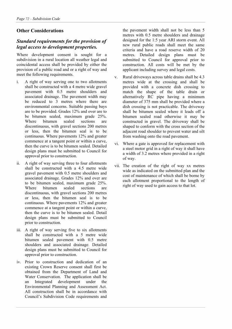
Page 72 – Subdivision Code
Other Considerations
Standard requirements for the provision of legal access to development properties. Where development consent is sought for a subdivision in a rural location all weather legal and coincidental access shall be provided by either the provision of a public road and or a right of way and meet the following requirements.
i. A right of way serving one to two allotments shall be constructed with a 4 metre wide gravel pavement with 0.5 metre shoulders and associated drainage. The pavement width may be reduced to 3 metres where there are environmental concerns. Suitable passing bays are to be provided. Grades 12% and over are to be bitumen sealed, maximum grade 25%. Where bitumen sealed sections are discontinuous, with gravel sections 200 metres or less, then the bitumen seal is to be continuous. Where pavements 12% and greater commence at a tangent point or within a curve, then the curve is to be bitumen sealed. Detailed design plans must be submitted to Council for approval prior to construction.
ii. A right of way serving three to four allotments shall be constructed with a 4.5 metre wide gravel pavement with 0.5 metre shoulders and associated drainage. Grades 12% and over are to be bitumen sealed, maximum grade 25%. Where bitumen sealed sections are discontinuous, with gravel sections 200 metres or less, then the bitumen seal is to be continuous. Where pavements 12% and greater commence at a tangent point or within a curve, then the curve is to be bitumen sealed. Detail design plans must be submitted to Council prior to construction.
iii. A right of way serving five to six allotments shall be constructed with a 5 metre wide bitumen sealed pavement with 0.5 metre shoulders and associated drainage. Detailed design plans must be submitted to Council for approval prior to construction.
iv. Prior to construction and dedication of an existing Crown Reserve consent shall first be obtained from the Department of Land and Water Conservation. The application shall be an Integrated development under the Environmental Planning and Assessment Act. All construction shall be in accordance with Council’s Subdivision Code requirements and
the pavement width shall not be less than 5 metres with 0.5 metre shoulders and drainage designed for the 1:5 year ARI storm event. All new rural public roads shall meet the same criteria and have a road reserve width of 20 metres. Detailed design plans must be submitted to Council for approval prior to construction. All costs will be met by the applicant including survey and legal costs.
v. Rural driveways across table drains shall be 4.3 metres wide at the crossing and shall be provided with a concrete dish crossing to match the shape of the table drain or alternatively RC pipe having a minimum diameter of 375 mm shall be provided where a dish crossing is not practicable. The driveway shall be bitumen sealed where it leads off a bitumen sealed road otherwise it may be constructed in gravel. The driveway shall be shaped to conform with the cross section of the adjacent road shoulder to prevent water and silt from washing onto the road pavement.
vi. Where a gate is approved for replacement with a steel motor grid in a right of way it shall have a width of 3.2 metres where provided in a right of way.
vii. The creation of the right of way xx metres wide as indicated on the submitted plan and the cost of maintenance of which shall be borne by each allotment proportional to the length of right of way used to gain access to that lot.
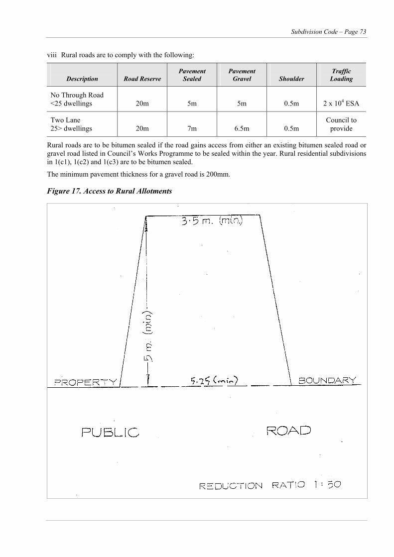
Subdivision Code – Page 73
viii Rural roads are to comply with the following:
Description
Road Reserve
Pavement Sealed
Pavement Gravel
Shoulder
Traffic Loading
No Through Road <25 dwellings
20m
5m
5m
0.5m
2 x 10⁴ ESA
Two Lane 25> dwellings
20m
7m
6.5m
0.5m
Council to provide
Rural roads are to be bitumen sealed if the road gains access from either an existing bitumen sealed road or gravel road listed in Council’s Works Programme to be sealed within the year. Rural residential subdivisions in 1(c1), 1(c2) and 1(c3) are to be bitumen sealed.
The minimum pavement thickness for a gravel road is 200mm.
Figure 17. Access to Rural Allotments
Page 74 – Subdivision Code
Element RU4 – Drainage
Objectives O1 To maintain road access in accordance with accepted levels of service.
O2 To minimise the risk of traffic accidents related to flooded roads in accordance with the accepted level of risk.
Performance Criteria Acceptable Solutions
The objectives may be achieved where:
P1 Lots are to be provided with flood free access. Habitable floor levels are to be 0.5 metres above 1 in 100 year ARI level for residential development in floodways and 0.3 metres in flood storage and flood prone areas.
All drainage design to be in accordance with Council’s Engineering Design Specifications, Chapter 5.
P2 Culverts and other drainage structures to be designed for 1 in 5 year Average Recurrence Interval.
Bridge design to conform to AUSTROADS Bridge Design Code 1992 and Waterway Design, 1994.
Culverts and small bridges within rights of way to be designed for the 1 in 5 year ARI level and designed to withstand the 1 in 100 year ARI flow.
P3 Bridges to be designed for 1 in 100 year Average Recurrence Interval.
Where it is proposed to carry out any excavations or fill within 40 metres of a watercourse, waterbody or wetland a 3A permit under the Rivers and Foreshores Improvement Act 1948 must be obtained from the Department of Land and Water Conservation.
P4 Overflow over roads to be in accordance with velocity and depth criteria.
Subdivision Code – Page 75
Element RU5 – Rural Landscape
Objectives O1 To minimise the impact of the subdivision on the natural environment.
O2 To enhance development by screening and providing colour, texture and spatial definition and linking natural to developed areas
Performance Criteria Acceptable Solutions
The objectives may be achieved where:
P1 Lot locations are to provide house sites which consider
views and visual impact
landscape potential and building suitability
wind and fire protection
Designation of building envelopes where appropriate. The use of Section 88B Restrictions to define appropriate building materials, colours and regulate height of buildings in sensitive locations.
Provision of landscaping.
See Figures 18 & 19.
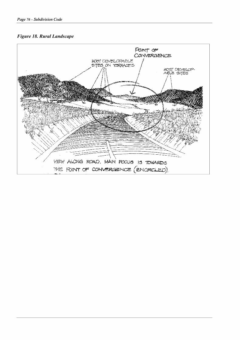
Page 76 – Subdivision Code Page 76 – Subdivision Code
Figure 18. Rural Landscape
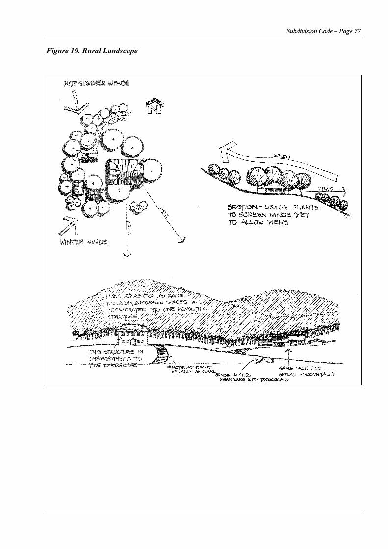
Subdivision Code – Page 77 Subdivision Code – Page 77
Figure 19. Rural Landscape
Page 78 – Subdivision Code
Element RU6 – Bushfire
Objectives O1 To provide rural subdivisions with bushfire control measures which can be readily defended
in a bushfire event.
O2 To control the construction of rural dwellings in high bushfire prone areas.
Performance Criteria Acceptable Solutions
The objectives may be achieved where: The provision of perimeter fire fighting access tracks.
The provision of public road or right of way access constructed to Council’s standard together with a secondary egress located in an east/west direction and all constructed in accordance with requirements of Council’s Engineering Design Specifications, Chapter D9.
P1 Subdivision must not be permitted in areas of high bush fire risk.
Buildings comply with the BCA requirements for construction in bushfire prone areas and with Council requirements. (see Fig 20).
P2 Subdivision is to be provided with legal primary and secondary access.
P3 Subdivision is designed to provide for a fuel reduced buffer area and the creation of building sites that minimise the risk of fire and fire fighters.
The provision of Section 88B restrictions and as follows
No building is to be constructed without being surrounded by a low bushfire fuel zone having a minimum radius of xx metres
No erection of dwellings on proposed lots without the provision of an additional 10,000 litre water storage suitable for use for bushfire purposes.
A backup dam, if required by Council’s Fire Control Officer, is to be provided on each lot and suitable for access by a bushfire tanker to a deep water point. The construction of dams for bushfire fighting purposes as affected by the NSW Governments Farm Dams Policy. Dams can only be constructed which capture 10% of the run off generated off their property in accordance with this policy. Dam capacities in excess of this harvestable right require licensing from Department of Land and Water Conservation.
Access is to be provided for bushfire fighting purposes along the perimeter bushfire track marked xxx. Where boundary fences cross the track a suitable unlocked gate is to be provided.
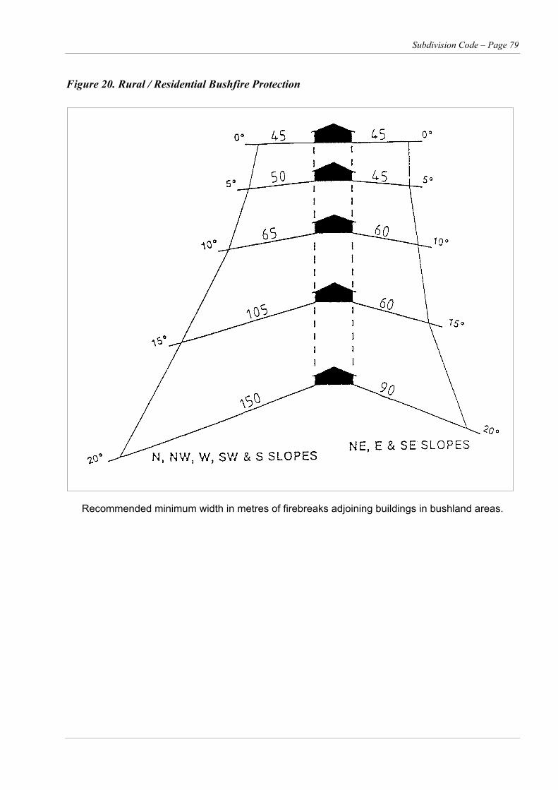
Subdivision Code – Page 79
Figure 20. Rural / Residential Bushfire Protection
Recommended minimum width in metres of firebreaks adjoining buildings in bushland areas.

Page 80 – Subdivision Code
Element RU7 – Rural Services
Objective O1 To provide public utilities to each allotment in an efficient and cost-effective manner.
Performance Criteria Acceptable Solutions
The objectives may be achieved where:
P1 Design and provision of utility services which are cost effective over their life cycle and incorporate provisions to minimise adverse environmental impact in the short and long term.
The design and provision of utility services conforms to the requirements of the relevant service authorities.
See Page 76, Other Considerations for detail and Council’s Engineering Design Specification Chapter D1.
Subdivision Code – Page 81
Other Considerations
Utility Services (Rural) Water Supply Water supply will not normally be required unless Council has a main directly adjacent to the proposed subdivision, and connection to that main will not disadvantage the main system. Special arrangements may be necessary in particular cases.
Where a Council main passes through a subdivision, and an easement has not previously been created, a 3 metre easement for water supply will be required to be created over the main through at least the created lots.
Effluent Disposal Effluent disposal for each application needs to be considered on its merit, but must comply with Onsite Sewerage Management DCP No. 78. There may be some allotments where aerated wastewater treatment systems will not be adequate to meet environmental or other concerns. In such cases Council may stipulate a specific type of effluent disposal system or require additional information.
Electricity The responsible Authority is Integral Energy. That Authority's rural subdivision policy requires the applicant to pay for the cost of high voltage overhead electricity supply to and throughout the subdivision and provide low voltage electricity to all lots up to 6 hectares in area. In addition, creation of easements over existing transmission lines through the area of a subdivision may be required.
It should be clearly understood by subdividers and future owners that the above rural subdivision policy means that future owners will be required to provide the cost of low voltage supply where not provided, including the cost of any sub-stations.
Significant savings in the final cost of low voltage supply to the lots in a rural subdivision can normally be effected by the Subdivider providing low voltage electricity supply to nominated house sites on each lot at subdivision stage. Shoalhaven City Council strongly urges subdividers to provide low voltage electricity supply to nominated house sites in rural subdivision. Integral Energy would require written application for such a supply together with a plan detailing the proposed house sites.
Should a future owner wish supply to another house site, any additional cost of adjusting the supply to
the new site would be the future owners responsibility.
Site Information Required for Major Drainage Structures To determine that the structure is compatible to the site, the following information is required:
1. Contour plan at 1:100 extending minimum 30 metres upstream and downstream and showing:
a. Contours well above the known or estimated highest flood level;
b. Location of road centre line including chainages;
c. Location of proposed structure;
d. Location of foundation test bores;
e. Location and value of Bench Mark.
2. Longitudinal section of road centre line at 1:100 showing:
a. Accurate profile of stream bed;
b. Location of structure;
c. Proposed road design levels, deck level, soffit level;
d. 1:5, 1:20 and 1:100 flood levels (so that capacity and stability can be assessed).
3. Characteristic cross sections at 1:100 (natural) minimum 10-metre intervals for minimum 30 metres upstream and downstream with 1:5, 1:20 calculated or observed flood levels shown.
4. Longitudinal section of stream extending 30 metres upstream and downstream at 1:100 (natural) showing levels at critical changes of grade and the location of the proposed structure.
Page 82 – Subdivision Code
Element ID1 – Industrial Subdivision
Objective O1 To provide for a wide range of general industrial development within the City for the creation of
employment.
Performance Criteria Acceptable Solutions
The objectives may be achieved where:
P1 Lots have the appropriate area and dimensions for the siting of buildings and vehicle manoeuvring and on-site parking.
Provide a range of lot sizes with the following minimum
Frontage 25 metres
Ideal ratio to depth 2:1 to 3:1
Area > 950 square metres
P2 Lots are dimensioned to take into account where possible existing vegetation or groups of trees which can be incorporated into the landscape design
Provide building set backs to provide landscaping and adequate on-site parking.
Battle-axe lots are not favoured unless the access strip is at least 8 metres wide and constructed to a width of 6 metres.
P3 The street system to be planned with a definite hierarchy and capable of conveying heavy transport traffic. Cul-de-sacs are highly undesirable.
Industrial subdivision road pavements shall be designed for heavy traffic loading requirements in accordance with DMR Form No. 76 and Council’s Engineering Design Specification, Chapter D2.
P4 The major and minor stormwater drainage system has the capacity to safely convey stormwater flows resulting from the relevant design storm under normal operating conditions
The design and construction of the minor storm drainage system is capable of accommodating the 1 in 20 year recurrence interval and meet the requirements of Council’s Engineering Design Specifications and Other Considerations.
P5 Design and provision of utility services including water, sewerage, electricity, street lighting and communication services, are cost effective over their life cycle and incorporate provision to minimise adverse environmental impact in the short and long term.
The design and provision of utility services conforms to the requirements of the relevant service authorities. Refer to Other Considerations for detail and Council’s Engineering Design Specification.
Building lines for Flinders Industrial Estate are 15 metres in Flinders Road, 10 metres for other roads.
The street design to enable the movement of all vehicles including B-doubles.
Subdivision Code – Page 83
Element ID2 – Site Analysis
Objective O1 To provide a site layout which meets the requirements for an efficient industrial operation for access,
services and works and services undertaken onsite.
Performance Criteria Acceptable Solutions
The objectives may be achieved where:
P1 A site analysis is undertaken which includes:
topographical features such as contours, location of existing buildings, services, water, sewerage, telecommunications, electricity.
Access, road widths, kerb and gutter, traffic generation.
Adjacent buildings, BCA requirements.
Drainage both natural and piped easements flooding.
There are no recommended Acceptable Solutions for this design element. However, it is expected as part of the development application, a detailed site analysis plan will be submitted which considers the matters listed in the Performance Criteria.
Page 84 – Subdivision Code
Table 8. Street Classification – Industrial
Road Classification
Road Reserve (metres)
Carriageway (metres)
Footpath Reserve (metres)
Kerb Type
Distributor Road 23 13 5 Barrier
Access Road 20 10 5 Barrier
Service Road (for rear access to lots)
10 9 1 Barrier
Note: Provision may need to be made for pathways and cycleway routes in specified circumstances and where these are required, the above widths may need to be increased. For standards for pathways and cycleways, see the residential standards in Element RE4. All other road design requirements will be as per the relevant parts of Element RE7. Cul-de-sacs are not favoured but where there is no alternative they are to have a pavement radius of 13 metres.
Other Considerations
Vehicle Parking All new industrial developments must provide onsite parking for all vehicles used by employees. Provision of 1 space per 100 square metres gross floor area for General Industry Factories applies.
Parking provision rate is increased when:
retailing is permitted onsite.
office space component is in excess of 20%.
employee parking demand is substantially less than the recommended rate.
refer to Car Parking DCP No. 18.
The number of onsite truck parking spaces provided must be on the basis of one space for each vehicle present at any one time (excluding those vehicles in the loading docks). Under no circumstances is the parking of trucks on contiguous public streets acceptable.
On any road, all vehicles should be able to complete their turning manoeuvres without crossing the road centre line. Minimum carriageway widths of 6.5 metres for two-way operation and 4.5 metres for one way operations are recommended for internal roads which do not allow parking.
There must be adequate provision for the manoeuvring, loading and unloading of vehicles on the site. AS 2890.2 provides further information on the requirements of service vehicle areas.
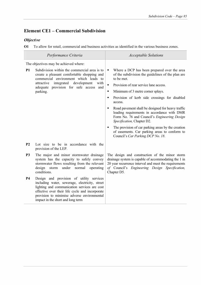
Subdivision Code – Page 85
Element CE1 – Commercial Subdivision
Objective O1 To allow for retail, commercial and business activities as identified in the various business zones.
Performance Criteria Acceptable Solutions
The objectives may be achieved where:
P1 Subdivision within the commercial area is to create a pleasant comfortable shopping and commercial environment which leads to attractive integrated development with adequate provision for safe access and parking.
Where a DCP has been prepared over the area of the subdivision the guidelines of the plan are to be met.
Provision of rear service lane access.
Minimum of 3 metre corner splays.
Provision of kerb side crossings for disabled access.
Road pavement shall be designed for heavy traffic loading requirements in accordance with DMR Form No. 76 and Council’s Engineering Design Specification, Chapter D2.
The provision of car parking areas by the creation of easements. Car parking areas to conform to Council’s Car Parking DCP No. 18.
P2 Lot size to be in accordance with the provision of the LEP.
P3 The major and minor stormwater drainage system has the capacity to safely convey stormwater flows resulting from the relevant design storm under normal operating conditions.
The design and construction of the minor storm drainage system is capable of accommodating the 1 in 20 year recurrence interval and meet the requirements of Council’s Engineering Design Specification, Chapter D5.
P4 Design and provision of utility services including water, sewerage, electricity, street lighting and communication services are cost effective over their life cycle and incorporate provision to minimise adverse environmental impact in the short and long term
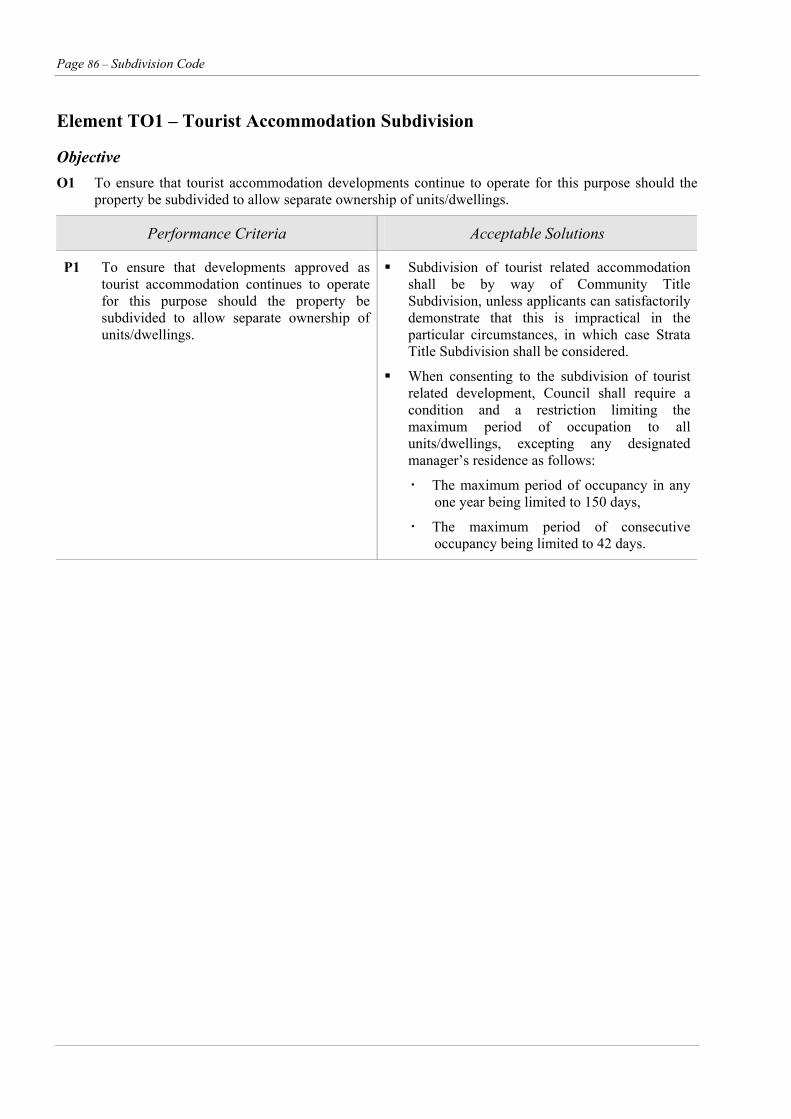
Page 86 – Subdivision Code
Element TO1 – Tourist Accommodation Subdivision
Objective O1 To ensure that tourist accommodation developments continue to operate for this purpose should the
property be subdivided to allow separate ownership of units/dwellings.
Performance Criteria Acceptable Solutions
P1 To ensure that developments approved as tourist accommodation continues to operate for this purpose should the property be subdivided to allow separate ownership of units/dwellings.
Subdivision of tourist related accommodation shall be by way of Community Title Subdivision, unless applicants can satisfactorily demonstrate that this is impractical in the particular circumstances, in which case Strata Title Subdivision shall be considered.
When consenting to the subdivision of tourist related development, Council shall require a condition and a restriction limiting the maximum period of occupation to all units/dwellings, excepting any designated manager’s residence as follows:
The maximum period of occupancy in any one year being limited to 150 days,
The maximum period of consecutive occupancy being limited to 42 days.

Subdivision Code – Page 87
P2 Applications PART 3
PROCEDURES Applications are to be made on Council's standard form and lodged together with:
At least 8 copies of a sketch plan showing the detail of the proposed subdivision (see also Section 2.4). Extra copies of the sketch plan are required when the application is referred to other government authorities.
P1 Procedures General
A subdivision application must be accompanied with:
The consent of the owner/s of the land (where the application is being submitted by any person other than the owner).
Statement of environment effects
A traffic study for applications with 200 or more allotments or if access is from an arterial road 50 or more allotments requires a traffic study.
The current application fee.
Additional information or report concerning the purpose and detail of the subdivision proposal and how specific problems will be overcome (eg. flooding).
The application must comply with all Acts relevant to subdivision. These include, but are not limited to the following:
Whether the application is Integrated Development. Clean Air Act 1961
Clean Waters Act 1970 Applicants are advised that all this detail must be completed before an application can be received and its consideration commenced.
Community Land Development Act 1989
Construction Safety Act 1912 P3 Integrated Development Crown Lands Act Integrated development is development that in order for it to be carried out requires development consent from Council and one or more of the approvals shown in Table 9.
Dam Safety Act 1975
Environmental Planning and Assessment Act 1979
Farm Dam Policy P4 Complying Development Fisheries Management Act 1994 A proposed subdivision can only be deemed complying development if it has been nominated as such in SLEP1985 and Amendments.
Heritage Act 1977
Land and Environment Court Act 1979
Local Government Act 1993
National Parks and Wildlife Act 1974
Native Vegetation Conservation Act 1997
Noise Control Act 1975
Occupational Health and Safety Act 1983
Pollution Control Act 1970
Rivers and Foreshores Improvement Act 1948
Soil Conservation Act 1938
Threatened Species Conservation Act 1995
Water Management Act 2000
Water Administration Act 1986
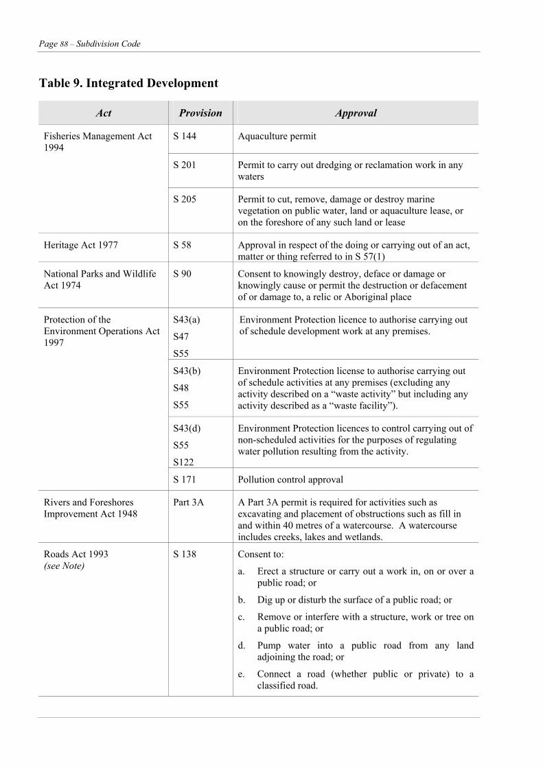
Page 88 – Subdivision Code
Table 9. Integrated Development
Act Provision Approval
Fisheries Management Act 1994
S 144 Aquaculture permit
S 201 Permit to carry out dredging or reclamation work in any waters
S 205 Permit to cut, remove, damage or destroy marine vegetation on public water, land or aquaculture lease, or on the foreshore of any such land or lease
Heritage Act 1977 S 58 Approval in respect of the doing or carrying out of an act, matter or thing referred to in S 57(1)
National Parks and Wildlife Act 1974
S 90 Consent to knowingly destroy, deface or damage or knowingly cause or permit the destruction or defacement of or damage to, a relic or Aboriginal place
Protection of the Environment Operations Act 1997
S43(a)
S47
S55
Environment Protection licence to authorise carrying out of schedule development work at any premises.
S43(b)
S48
S55
Environment Protection license to authorise carrying out of schedule activities at any premises (excluding any activity described on a “waste activity” but including any activity described as a “waste facility”).
S43(d)
S55
S122
Environment Protection licences to control carrying out of non-scheduled activities for the purposes of regulating water pollution resulting from the activity.
S 171 Pollution control approval
Rivers and Foreshores Improvement Act 1948
Part 3A A Part 3A permit is required for activities such as excavating and placement of obstructions such as fill in and within 40 metres of a watercourse. A watercourse includes creeks, lakes and wetlands.
Roads Act 1993 (see Note)
S 138 Consent to:
a. Erect a structure or carry out a work in, on or over a public road; or
b. Dig up or disturb the surface of a public road; or
c. Remove or interfere with a structure, work or tree on a public road; or
d. Pump water into a public road from any land adjoining the road; or
e. Connect a road (whether public or private) to a classified road.
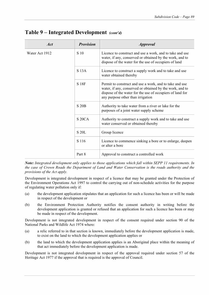
Subdivision Code – Page 89
Table 9 – Integrated Development (cont’d)
Act Provision Approval
Water Act 1912 S 10 Licence to construct and use a work, and to take and use water, if any, conserved or obtained by the work, and to dispose of the water for the use of occupiers of land
S 13A Licence to construct a supply work and to take and use water obtained thereby
S 18F Permit to construct and use a work, and to take and use water, if any, conserved or obtained by the work, and to dispose of the water for the use of occupiers of land for any purpose other than irrigation
S 20B Authority to take water from a river or lake for the purposes of a joint water supply scheme
S 20CA Authority to construct a supply work and to take and use water conserved or obtained thereby
S 20L Group licence
S 116 Licence to commence sinking a bore or to enlarge, deepen or alter a bore
Part 8 Approval to construct a controlled work
Note: Integrated development only applies to those applications which fall within SEPP 11 requirements. In the case of Crown Roads the Department of Land and Water Conservation is the roads authority and the provisions of the Act apply.
Development is integrated development in respect of a licence that may be granted under the Protection of the Environment Operations Act 1997 to control the carrying out of non-schedule activities for the purpose of regulating water pollution only if:
(a) the development application stipulates that an application for such a licence has been or will be made in respect of the development or
(b) the Environment Protection Authority notifies the consent authority in writing before the development application is granted or refused that an application for such a licence has been or may be made in respect of the development.
Development is not integrated development in respect of the consent required under section 90 of the National Parks and Wildlife Act 1974 where:
(a) a relic referred to in that section is known, immediately before the development application is made, to exist on the land to which the development application applies or
(b) the land to which the development application applies is an Aboriginal place within the meaning of that act immediately before the development application is made.
Development is not integrated development in respect of the approval required under section 57 of the Heritage Act 1977 if the approval that is required is the approval of Council.
Page 90 – Subdivision Code
P5 Determination of Applications Applications considered under the provisions of the EP & A Act are required to be determined within 40 days. An application which is illegible or unclear may be rejected within 7 days. Additional information may be sought within 21 days and which stops the 40 day determination period. In the case of Integrated Development, the matter must be determined within 60 days.
Upon determination of any application, a written notification will be sent to the applicant stating that consent/approval has been granted subject to detailed conditions or that consent/approval has been refused (with reasons).
P6 Request for Reconsideration and/or Rights of Appeal
Where an applicant is dissatisfied with the determination of his application, he may request reconsideration of a refused application, provided the request is received within 28 days after the date of determination and the prescribed fee paid. Details of the reasons for reconsideration must be submitted with the request. See Section 82A of EP & A Act
Alternatively, (and preferably as a last resort), the applicant may lodge an appeal with the Land and Environmental Court, such appeal must to be lodged with the Court within twelve months of receipt of Council's determination of the application. See Section 97 of the EP & A Act.
P7 Staging Where development consent only is required for the first or part stages of a subdivision, eight (8) copies of the plan for the first stage must be submitted, together with copies of the overall plan of the subdivision on which the staged development proposal is clearly marked. The overall plan will become a development strategy plan, if adopted by Council. Each stage of the subdivision will be considered separately and if approved issued with a consent.
Where consent has been issued for the overall development a section 96 application for each stage will be required.
P8 Development/Subdivision Applications
A site analysis with plans of the land to which the application relates are to accompany the
development application and conform with the design element of this Code.
P9 Fees and Charges
P9.1 Application Fees All applications for the subdivision of land will require the payment of application fees at the time of submitting each application. The schedule of fees is available from the Development and Environmental Services Group.
P9.2 Contributions – Section 94 and Section 64
a. Urban Residential Any development consent issued for the
subdivision of land for residential purposes will generally attract the payment of a cash contribution at the time of release of the plan of survey:
i. Water supply and/or sewerage headworks and/or special charge.
ii. Community facilities, open space – either dedication of land where appropriate or cash contribution for active and passive recreation, bushfire, road upgrading.
b. Rural Residential and Rural The following contributions are generally
imposed at the time of development consent:
i. Water supply and sewerage headworks charge where applicable.
ii. Community facilities, passive recreation – either dedication of land where appropriate or cash contribution in accordance with the plan, Active Recreation, Bushfire, Road upgrading.
P10 Approvals Subdivision applications are determined in accordance with the EP & A Act 1979.
Applications may be granted a consent either unconditionally or subject to conditions.
A deferred commencement consent may be granted subject to a condition that the consent is not to operate until the application satisfies the Consent Authority in regards to any matter specified in the conditions.
A development consent may be granted as a staged development. A development consent for a
Subdivision Code – Page 91
subdivision lapses five (5) years after the date of approval. The consent does not lapse if engineering or construction works relating to the subdivision is physically commenced on the land to which the consent applies. Integrated Development approvals lapse after three (3) years. Upon receiving an approval which requires physical work to be undertaken a Principal Certifying Authority must be nominated. This may be Council or an Accredited Certifier.
Where road and drainage works are required to be constructed, a construction certificate must be obtained certifying the engineering plans where relevant a Part 3A permit under the Rivers and Foreshore Improvement Act is to be obtained from Department of Land and Water Conservation. A compliance certificate is to be obtained in regards to the execution of those works.
A Construction Certificate and a Compliance Certificate may be issued by Council and or an accredited certifier. In regards to the provision of water and sewerage a Compliance Certificate must be obtained from Shoalhaven Water.
A Subdivision Certificate will not be issued by Council or a Principal Certifying Authority unless all development conditions have been met. A Principal Certifying Authority can only be appointed if the subdivision is of a kind identified by SLEP 1985.
P11 Occupational Health and Safety Particular attention is drawn to the provisions of the OH & S Act and Construction Safety Act and the obligations imposed to make a full assessment of all safety aspects of the project and to ensure the safety of the general public and construction workers at all times.
P12 Workers Compensations Contractors engaged on development/subdivisional works must carry current workers compensation insurance on all works as required by Statute.
P13 Variations to Approval In any discussions with Council employees the applicant shall ensure any advice that he obtains and intends to act upon is ratified by personnel with delegated authority in these respective matters. Any amendments to the Development Consent, agreed to verbally by Council Officers, should be confirmed in writing by way of a Section 96 application.
Should the applicant or his representative choose to act on such unconfirmed advice then rectification works at full cost to the applicant may be required.
P14 Engineering Design Plans and Specifications
P14.1 Construction Certificate Where required as a condition of subdivision approval engineering plans and specifications must be submitted to Council or an accredited certifier for approval.
All designs are to be in accordance with the conditions of consent and Council’s Engineering Design Specification.
It is desirable to make a preliminary submission (one set of prints) and any amendments may then be made prior to the final submission.
Plans and specifications are to be prepared and submitted by suitably qualified and experienced persons. All plans and specifications for road works and drainage works must be submitted by a Civil Engineer of NPER3 standing or Registered Surveyor accredited from the Institute of Surveyors for the undertaking of Subdivisional Civil Works.
Plans and specifications for all sewer pumping stations and structural works such as flood control structures, bridges over 6 m clear span or retaining walls in excess of 1 m in height must be submitted by a Civil or Structural Engineer.
P14.2 Plan Preparation A number of standard drawings have been prepared to assist with plan preparation and are attached to Council’s Engineering Design Specification, chapters 10 and 11. All engineering drawings must be submitted on Australian Standard A1 or A2 size sheets. All levels are to be referenced to Australian Height Datum A.H.D.
P14.3 Plans – Residential Roadworks P14.3.1 Plan Details Plans are to be prepared in accordance with the following details:
general construction plan;
landscaping plan;
road details (plan, longitudinal / constructions);
intersection plan;
Page 92 – Subdivision Code
catchment plan; Intermediate points on long straights no more than 100m intervals, there variation exceeds + 10% from the approved width. general drainage plan;
drainage longitudinal sections; Gutter invert levels to be shown at: special drainage structures.
All T.P.'s The above list may be shortened for small subdivisions, provided all necessary information is clearly shown.
Crests
Sags
P14.3.2 General Construction Plan End of straight grades
As required on flat grades This plan shows all work except drainage at a ratio of 1:1000 and provide: Location of all Vehicle Entries where applicable to
be shown. The location of all pits and pipes within the street alignments are to be shown where they may conflict with the unrestricted vehicular entry to lots.
extent of kerb and gutter;
extent of pavement construction of various thicknesses;
extent of bus stop construction; P14.3.4 Intersection Plan sign posts; These drawings are only required in special cases
and drawn to a ratio of 1:200. They should show all data necessary for setting out the kerbs and show finished contours on the road surface.
fender posts;
typical cross sections;
pathway details; P14.3.5 Rural Road Plans
proposed landscaping including tree plantings. The following drawings should be prepared generally in conformity with Council’s Engineering Design Specification and the Roads and Traffic Authority. Reduction ratios to be as follows:
Where any work is to take place adjacent to existing properties which are outside the subdivision, details of any alterations to levels, fencing or other improvements are to be shown. Evidence of compliance by the adjoining owners will be required.
i. Plan and longitudinal sections:
RR 1:2000 horizontal P14.3.3 Road Plans RR 1:200 vertical Plans are to be prepared in accordance with the following details and show bearings and centreline chainages, kerb return diagrams, existing services, improvements and numbered allotments.
ii. Cross sections:
RR 1:100 natural
(30 metre intervals
20 metres on curves) i. Cross sections of all proposed roads at intervals of fifteen (15) metres and at lesser intervals where necessary RR 1:100 natural. iii. All provisions for drainage and relevant
information and calculations. ii. Longitudinal sections of all kerb returns and
kerb profiles in cul-de-sacs closer or similar locations shall be provided.
iv. Road-side furniture.
P14.4.1 Stormwater Drainage Plans iii. Typical cross sections of roads proposed RR
1:100. Catchment area plan – Reduction Ratios as appropriate but not less than 1:4000 and shall show the area in hectares drained by each headwall, gully pit, junction pit, or other pick up points to enable pipe, channel etc, size to be determined. The vertical fall from the extremity of the catchment to each pick-up point shall be supplied and a note made of any flood marks or flooding information known to local residents. Defined watercourses and
iv. Footpath widths are to be shown to face of kerb at:
All T.P.'s
Centre of Curves
Beginning and end of construction
Subdivision Code – Page 93
drains, either natural or man-made and marsh/swamp areas shall be clearly defined on the catchment plan.
P14.4.2 Plans, Long Sections, Cross Sections
A drainage plan shall be supplied on which is shown a locality sketch, north point, invert levels, pipelines, easements, lot boundaries, gully pits, headwalls and numbers and junction pits, channels, watercourses, table drains, overflow paths, pathways, access ways, roadways, all notable vegetation, natural and man-made features including control structures, energy dissipaters, detention basins, dams, edge of bitumen, kerb and gutter, fences, all services and roadside furniture etc. proposed and existing, where appropriate, together with curve geometry, recover marks with levels, centre line bearings, chainages along pipelines, channels, watercourses, areas of cut and fill etc.
Longitudinal sections shall show chainage, existing grades, reduced levels to Australian Height Datum of natural surface and finished surface levels, floor levels, pavement levels and invert levels of all open drains/channels/ watercourses and pipelines, pits.
Design grades, catchment discharge, water surface profiles/hydraulic grade line, buildings and floor levels on adjacent properties, pit entry details, pit and line numbers, pipe class, overflow paths allowing for blockage effects, outlet details including erosion/scour protection and any structures such as energy dissipaters, surcharge structures, debris control structures, calculated size of channels, pipelines, pipe class, velocities etc. shall also be shown.
Generally survey information is to be provided for a minimum of 30 metres upstream and downstream of the works for culverts 1050mm diameter and larger. Accurate levels, position and size of all services (telephone, gas, electricity, water, sewer etc.) crossed by the pipelines/channels shall be shown on both the longitudinal, plan and cross sections.
The details of any special feature affecting run off, such as stormwater concentration from or to adjoining lands, the nature of the soil onsite and/or the presence of rock to be supplied.
The point of discharge into Council's drainage system shall be approved by council. The cost of work involved in constructing drainage from the development to the point of discharge shall be met by the developer/subdivider. Before construction
commences in any footpath, a Section 138 permit must be obtained from Council.
In cases where discharge of stormwater must take place over downstream properties, easements in favour of the applicant's property shall be obtained.
P14.4.3 Contour Plans In cases where lands either appear to be difficult to protect by drainage or are in areas which may be utilised for sewerage reticulation, then plans showing existing contours at one (1) metre vertical intervals are to be provided or, if slopes are less than 1 in 100, at interval of half (0.5) metres. At least two contours are to be provided across each lot extending beyond the boundary of the site a distance sufficient to show any design/construction constraints, minimum 20 metres.
P14.4.4 Scales Appropriate to the size of the works being shown but generally the scales to be adopted are as follows.
i. Site Drainage and associated plans:– 1:500
ii. Longitudinal section of centre line of pipelines and open channels:– Horizontal 1:500 and Vertical 1:100
iii. Cross Section :–1:100 Natural
iv. Detail Drawings of special structures :– 1:20
v. ll drainage lines identified with line numbers, pipe diameters and pipe classes.
vi. ll drainage structures numerically identified.
vii. he following information shall be shown on each section reading from the base:
Running chainage
Road chainage (where applicable)
Finished surface levels
Invert levels at pit inlet and outlet
Grade in percent
Pipe diameter and class
Capacity in cumecs
Discharge flow in cumecs
Discharge velocity in cumecs
Page 94 – Subdivision Code
d. AHD level of the highest point of a water main to allow an assessment of the adequacy of available pressures and flow rates.
P14.4.5 Flood Prone Areas Water surface levels for the 1 in 20 year and 1 in 100 year ARI flows are to be specified on the plan for any natural watercourse, trunk drainage system or a major system flow path. Development within such areas must be consistent with the State Government Flood Prone Land Policy as set out in the “Flood Plain Management Manual: The management of flood liable land – January 2001”. Council’s Floodplain Management Plan for the area should also be consulted.
e. A typical cross section of trench showing the backfill materials and depths.
f. Detail design drawings of any pumping station or reservoir.
Sewerage drawings shall show the following information:
a. Plan locations of existing mains and extensions to service the subdivision.
P15 Site Regrading b. Locations of manholes, sidelines and junctions.
c. Any part of a block which cannot be served from its proposed sewer junction is to be shaded. Contours will be required on the plan to establish any such areas.
Where any lot is the subject of site regrading, the following is required:
a. Finished surface levels are to be recorded by spot levels of the regraded area and the natural surface area adjacent. d. Long sections of sewers shall also give the
following information: b. Spot levels are to be taken and recorded on
plans at: Chainages at junctions and manholes from an existing main, a new section of truck main or a new pumping station. Allotment corners
Centre of front and rear boundaries Surface and invert levels at manholes. Depths are also to be shown. 12 metres from front alignment on side
boundaries and centre of lot. Pipe materials, slope and the spacing of trench stops or concrete bulkheads, in accordance with Council’s Engineering Design Specification, chapter D11.
c. Major site regrading (ie. cut or fill over 0.5m in depth) is to be recorded by new contours.
d. Depths of fill to be indicated by shading or crosshatching to intervals of 0.5m (for use by Council's Development Services Department for determining the depth of piered footings).
Any special treatment when minimum cover requirements are not achievable.
e. A typical cross section of the trench showing the backfill materials and depths. e. See Standard Drawing Ref. 263718.
f. Civil design details of any pumping stations including materials is to comply with Council’s Engineering Design Specification, chapter D11.
P16 Water Supply and Sewerage Drawings
Water supply plans shall show the following information: P17 Landscaping Plans a. Plan location of existing mains and proposed
extensions to service the subdivision. a. Detailed vegetation survey of the proposed subdivision showing the location of all trees three (3) metres or more in height. b. Location of hydrants, valves and water
services. The water main fittings required are to be detailed. b. Details of proposed plantings including the
type of species. c. AHD level of the lowest point of a water main
to allow an assessment of the suitability of pipe class.
Subdivision Code – Page 95
P18 Design and Construction Specifications
All road construction works (rural and urban) shall be carried out in accordance with Engineering Design Specification.
Construction of roads shall not be commenced until plans and specifications are approved by Council or an accredited certifier and a construction certificate issued and Council has been notified in writing two (2) days in advance of the contractor commencing work.
P19 Erosion Control Measures Submission of an erosion and sediments control plan shall be as follows:
(a) Stage 1
Preliminary plans for subdivisions shall clearly indicate the approximate limit of clearing, the approximate limits of grading which may not be the same as for clearing, together with tentative methods for erosion and siltation control. Areas to be disturbed by clearing or grading on which unstable or dispersable soils exist must be specifically indicated and in accordance with procedures provided in the NSW Department of Housing Manual "Managing Urban Stormwater Soils and Construction".
(b) Stage 2
Plans for the control of erosion and sedimentation shall be submitted to Council's Development Services Department or an accredited certifier at the time construction plans and site plans are submitted for approval.
i. Plan of works Reduction Ratio 1:500.
ii. Cross sections and longitudinal profiles as appropriate.
(c) Stage 3
The erosion control measures detailed on the approved engineering plans are to be implemented as part of the initial site works. Failure to adequately control erosion will result in a stop work notice being issued until those facilities have been provided.
P20 Testing The full cost of all pavement design and pavement testing is to be met by the subdividers. Test results will be required in accordance with requirements
detailed in Council’s Engineering Design Specification, Chapter D2. Test results are required to ensure that the material supplied and the work carried out conform with the approved specification.
P21 Compliance Certificate All Civil works (road and drainage) undertaken must be issued upon completion of the work with a certificate of compliance prior to the issuing of a subdivision certificate.
A certificate of compliance certifies that engineering works comply with the requirements of the construction certificate. The certificate of compliance can only be issued by Council or an accredited certifier.
P22 Contractors and Sub-Contractors
The contractor must have recent experience and competence in subdivision works and be familiar with current construction techniques and procedures in the following works:
a. Earthworks
b. Roadworks
c. Concreting
d. Water Supply
e. Sewerage
f. Stormwater
Contractors may engage sub-contractors to carry our specific works. Details of proposed sub-contractors for specific works are to be submitted to Council for approval before any work commences.
The Contractor and all employed personnel shall at all times fully comply with all Acts and Regulations of Government and statutory authorities having jurisdiction over the workplace or site.
Additionally, all Contractors working on public property shall comply with the statutory and Council Acts, Regulations, Codes and Policies and carry Public Liability Insurance to the value of $10 million dependent on risk exposure.
P22.1 Water Supply or Sewerage Cut-ins Where connection is to be made to existing water supply/sewerage facilities, such as pipelines, manholes, pump stations, all such work will be
Page 96 – Subdivision Code
See Council’s Engineering Design Specification, chapters D10 and D11.
carried out by Shoalhaven Water at the subdividers cost.
P23.4 Sub-grade P23 Inspections notice is to be given when sub-grade is ready
for inspection and conduits have been laid Where Council is the accredited certifier, the whole of the work is to be carried out to the satisfaction of the Subdivision Development Director or his representative. In the case of water and sewerage works, Shoalhaven Water is the accredited certifier. Uninterrupted access is to be available at all times.
pavement construction must not commence until the sub-grade has been tested and accepted
P23.5 Kerb and Gutter A compliance certificate will be issued by Council for each of the following stages where Council is the accredited certifier. Site inspections will be required for each of the stages. Adequate notice is to be provided by the contractor.
notice is to be given when base course pavement materials has been brought to the correct state of level and compaction and that an inspection is required prior to the laying of formwork, or the laying of kerb and gutter by the use of a kerbing machine. Where Council is not the Accredited Certifier, A
compliance certificate will need to be obtained from a nominated accredited certifier. P23.6 Pavement Construction
notice is to be given when each pavement course is ready for inspection P23.1 Site Regrading and Clearing
notice is to be given when the site is to be regraded and cleared
each subsequent course is not to be commenced until tested and inspected
notice is to be given when erosion control measures have been completed P23.7 Pavement Surfacing
notice shall be given of intention to surface pavements notice is to be given to determine the removal
of trees and vegetation prior to the commencement of earth works if weather conditions necessitate any alteration,
the Subdivision Development Director is to be notified as soon as possible P23.2 Stormwater Drainage and Utility
Service Conduits The subdivider will be required to meet the full cost of any inspections required outside normal Council working hours and will be required to agree in writing to meet those costs prior to any such work being authorised.
notice is to be given when trenches are to be opened
notice is to be given when pipes are laid and jointed
P24 Insurance trenches must not be backfilled until approval has been obtained
The accredited certifier shall take out a professional indemnity insurance indemnifying himself and Council against claims in regard to any alleged inadequacies or incompetence in the design and construction of individual civil engineering works. The level of indemnity insurance must be in accordance with the regulations attached to the EP&A Act Part 4C.
P23.3 Water and Sewer Mains notice is to be given when trenches are to be
opened
notice is to be given when pipes are laid and jointed
trenches must not to be backfilled until approval has been obtained Contractors shall hold third party and public liability
insurance for a minimum value of $5 million, dependant on risk exposure for work on public property.
notice is to be given prior to the pouring of all concrete for sewer manholes and pumping stations
Subdivision Code – Page 97
P25 Work-as-Executed Plans f. Longitudinal sections of pipelines.
g. Extent of partial drainage of property if applicable.
Following completion of the work, one full set of work-as-executed plans and/or transparent film suitable for reproduction and/or compatible computer disk, is to be submitted and retained by Council. The work-as-executed plans are to include the following:
h. Details of sewerage pumping stations and rising mains where applicable.
All works-as-executed plans shall bear the consulting engineer's or consulting surveyor's certification stating that all information shown on the plans is accurate, and in accordance with Forms 1 and 2. (See Appendix). It should be noted that only Registered Surveyors can delineate on public record information which relates to cadastral boundaries.
P25.1 General a. A complete set of Council approved plans
clearly marked "work-as-executed".
b. Any changes to approved road levels, stormwater pipe sizes, grades, sub soil drains etc to be marked. A Subdivision Certificate will not be issued nor the
plan of survey released, or where a construction bond has been lodged to allow the early release of the plan of survey, the performance bond will not be discharged until satisfactory work-as-executed plans have been submitted.
c. Interallotment drainage junctions.
d. Site regrading – Where any lot is the subject of site regrading, the following is required:
i. Finished surface levels are to be recorded by spot levels of the regraded area and the natural surface area adjacent. P26 Subdivision Certificate
ii. Spot levels are to be taken and recorded on plans at:
The original transparency of each plan of survey and eight (8) copies (10 copies of subdivision located in Sussex Inlet and further south) of each are to be submitted to Council for the issue of a Subdivision Certificate.
Allotment corners
Recorded by new contours
iii. Depths of fill to be indicated by shading or crosshatching to intervals of 0.5m (for use of Council's Development Services Department in determining the depth of piered footings). See Standard Drawing Ref 263718.
The Section 88B Instrument must incorporate Council as party benefited or party to release, vary or modify as appropriate for any easement or restrictions as to user required as a condition of development consent. Provision must be made for the signature of Council on every page of the instrument.
P25.2 Water Supply P27 Bonding of Works in
Subdivision a. Pipe details including size, type and class.
b. Ties to property boundaries of stop valves, hydrants tees, scours, air valves etc. In order to achieve an early release of the plan of
survey by the issuing of a Subdivision Certificate, applicants sometimes request bonding of certain works in subdivisions. Generally, this procedure is not favoured, as problems can arise with servicing of lots not being complete prior to buildings commencing. However, Council may agree to the release of final plan of survey in the following circumstances:
c. Size and location of services to each property.
P25.3 Sewerage a. Pipe details including size, type, class and
grade.
b. Invert of incoming lines and surface levels of manholes.
i. Where roadworks are involved, only where such works have progressed to the stage of providing all-weather access to all lots and security in the form of a cash deposit or irrevocable bank guarantee is provided for the completion of the work and a contract between
c. Distance between manholes
d. Junction details including distance from downstream manhole, depth and length of sideline if appropriate.
e. Ties to property boundaries of manholes.

Page 98 – Subdivision Code
the applicant and the Contractor for the completion of the works has been sighted by Council.
ii. Provided utility service road crossings are installed, Council may accept an irrevocable bank guarantee for the provision of either water and/or sewerage works in a subdivision in an amount to be determined by Council.
P27.1 Assessment of Bond Amount Where the work is to be carried out by the applicant's contractor, the bond is to be for full contract value of outstanding work plus 10%, further 5% of the contract price will be retained for maintenance for a period of 6 months after road works have been bitumen sealed.
The payment of fees and contributions to enable (early) release of the plan of survey, must be made unconditionally and Council will not accept compliance with conditions of consent made under "protest" or "subject" to further discussion" etc.
P27.2 Reduction of Bond The bond amount may be progressively reduced as the work covered by the bond is carried out but at no time will the bond amount fall below 10% of the contract amount or the estimated total cost of the outstanding works. The applicant will be required to lodge a schedule of quantities of all outstanding works to enable the bond amount to be determined.
P28 Completion of Works and Certification
On practical completion of construction works, a compliance certificate will be issued by Council or an accredited certifier (except for water and sewerage where Shoalhaven Water is the accredited certifier) and which indicates that the whole of the works have been carried out in accordance with the construction certificate and specification. If the whole of the works are considered satisfactory the Subdivision Development Director will agree to a date (the date of practical completion) on which the whole of the works are considered to have entered into the maintenance period. (Forms 1 and 2).
Separate components of works will not be accepted into maintenance individually.
P29 Maintenance of Works Notwithstanding any contractual agreement an applicant may have with a contractor for any
portion of the work within a subdivision, Council requires a maintenance period for all work prior to the final acceptance of the work; and this period shall be at least six (6) months after the works are certified complete by the Subdivision Development Director or the accredited certifier.
Council will accept copies of test results throughout the program of each subdivision. All requests for Council's acceptance of subdivisions into maintenance are to be made in writing including documentation of all test results obtained.
In the case of sewerage pumping stations, these will not be accepted into maintenance until they are fully operational and have satisfactorily completed pump performance tests. The applicant will be required to meet all the maintenance costs associated with any failure which may occur in the operation of the pumping station from the time the pumping station is accepted into service by Council to the end of the maintenance period.
In the case of water and sewerage main construction, these will not be accepted into maintenance until they have been connected to Council's reticulation, which will only occur after the submission of work-as-executed plans.
P30 Naming of Roads The naming or re-naming of roads and streets should meet the following criteria:
Will not duplicate existing names within the City.
Be reasonably easy to spell and pronounce.
Will not use compass directions as prefix or suffix (eg north, south etc) if this can be avoided.
Names of people to be used only to mark notable public achievements or pioneers of the area. A Council resolution is required if the name is to be that of a living person. The name, should preferably be the surname only.
A relationship to the locality eg flora and fauna, aboriginal, historical etc is desirable but not obligatory.
The suffix “Place” or “Close” or some other appellation with a similar meaning should be used for cul de sacs.
For large subdivisions with multiple streets an overall theme for the naming of streets and parks is recommended.
Subdivision Code – Page 99
All private accesses (including private thoroughfares created under Community title) should be clearly identified with the statement “private”.
Due consideration be given to the use of Aboriginal names for appropriate features within the City (added through resolution of 17 December 1991 – minute no. 91.3218).
Private access over private land be clearly marked on the street name as “private” and the sign not include Council’s logo. These applications do not require advertising, but must comply with Council’s policy. All costs involved to the borne by the applicant. Where the access is used by more than one owner, consent from all land owners be obtained and Council’s rural numbering policy be used (added through resolution of 17 August 1993 – minute no. 93.2072).
Accesses over privately maintained Crown Road Reserves be signposted, comply with Council’s policy and be advertised, including notification to NSW Department of Land and Water Conservation. The sign not include Council’s logo and have the addition of the words “privately maintained”. All costs involved to be borne by the applicant. All affected owners will be notified and where significant objections are received the matter would be reported back to Council. Council’s rural numbering policy will also be used. (added through resolution of 17 August 1993 – minute no. 93.2072).
Where roads are only maintained by Council for part of their length, the remainder being normally a Crown road reserve, then a sign be erected at the end of the Council maintained section indicating that Council does not maintain the road beyond this point (added through resolution of 17 August 1993 – minute no. 93.2072).
Long Service Levy under the Environmental Planning and Assessment (Building code of Australia Regulation, 1999) is required to be paid to Council before a construction certificate can be issued. The levy is charged at the rate of 0.02% of construction cost where works are valued at more than $25,000.


Subdivision Code – Page 101
APPENDICES
Appendix 1 Application Guidelines – Residential Land Subdivision
Appendix 2 Application Guidelines – Rural Land Subdivision
Appendix 3 Glossary
Appendix 4 Form 1 Work-as-Executed Plans
Form 2 Drainage Easements
Form 3 Certificate of Compliance
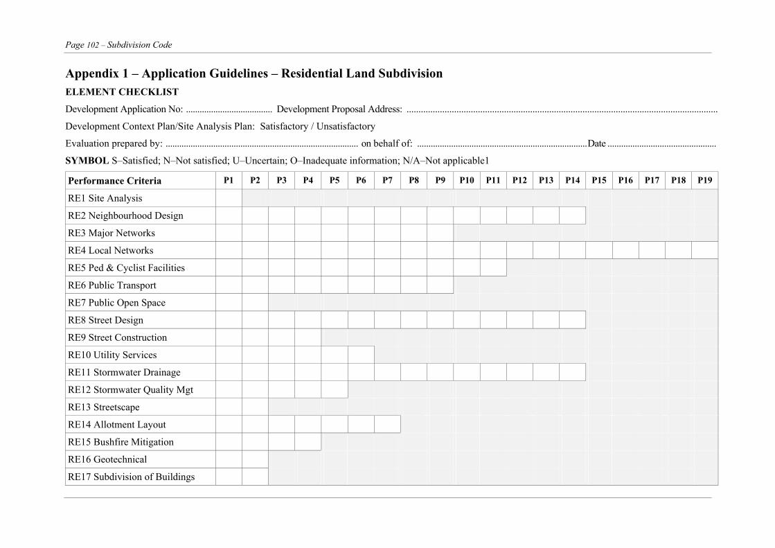
Page 102 – Subdivision Code
Appendix 1 – Application Guidelines – Residential Land Subdivision ELEMENT CHECKLIST
Development Application No: ...................................... Development Proposal Address: ...................................................................................................................................
Development Context Plan/Site Analysis Plan: Satisfactory / Unsatisfactory
Evaluation prepared by: ..................................................................................... on behalf of: ...........................................................................Date ................................................
SYMBOL S–Satisfied; N–Not satisfied; U–Uncertain; O–Inadequate information; N/A–Not applicable1
Performance Criteria P1 P2 P3 P4 P5 P6 P7 P8 P9 P10 P11 P12 P13 P14 P15 P16 P17 P18 P19
RE1 Site Analysis
RE2 Neighbourhood Design
RE3 Major Networks
RE4 Local Networks
RE5 Ped & Cyclist Facilities
RE6 Public Transport
RE7 Public Open Space
RE8 Street Design
RE9 Street Construction
RE10 Utility Services
RE11 Stormwater Drainage
RE12 Stormwater Quality Mgt
RE13 Streetscape
RE14 Allotment Layout
RE15 Bushfire Mitigation
RE16 Geotechnical
RE17 Subdivision of Buildings
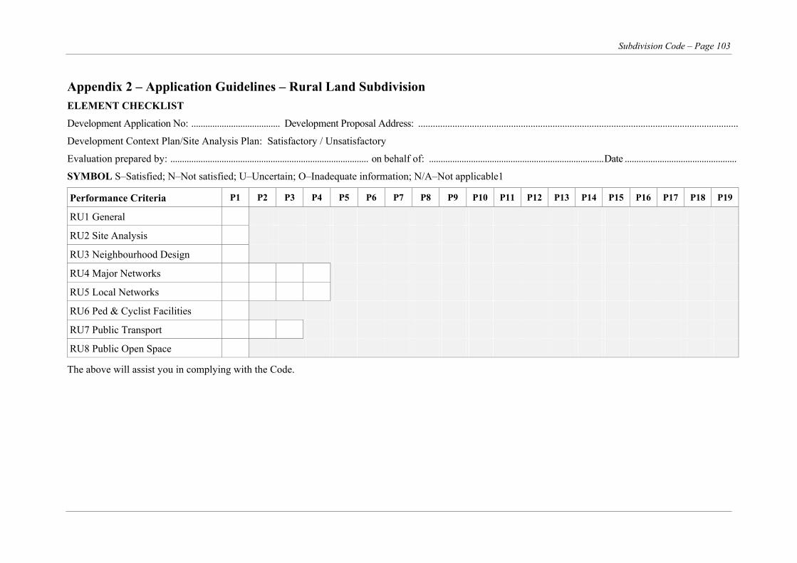
Subdivision Code – Page 103
Appendix 2 – Application Guidelines – Rural Land Subdivision ELEMENT CHECKLIST
Development Application No: ...................................... Development Proposal Address: ...................................................................................................................................
Development Context Plan/Site Analysis Plan: Satisfactory / Unsatisfactory
Evaluation prepared by: ..................................................................................... on behalf of: ...........................................................................Date ................................................
SYMBOL S–Satisfied; N–Not satisfied; U–Uncertain; O–Inadequate information; N/A–Not applicable1
Performance Criteria P1 P2 P3 P4 P5 P6 P7 P8 P9 P10 P11 P12 P13 P14 P15 P16 P17 P18 P19
RU1 General
RU2 Site Analysis
RU3 Neighbourhood Design
RU4 Major Networks
RU5 Local Networks
RU6 Ped & Cyclist Facilities
RU7 Public Transport
RU8 Public Open Space
The above will assist you in complying with the Code.
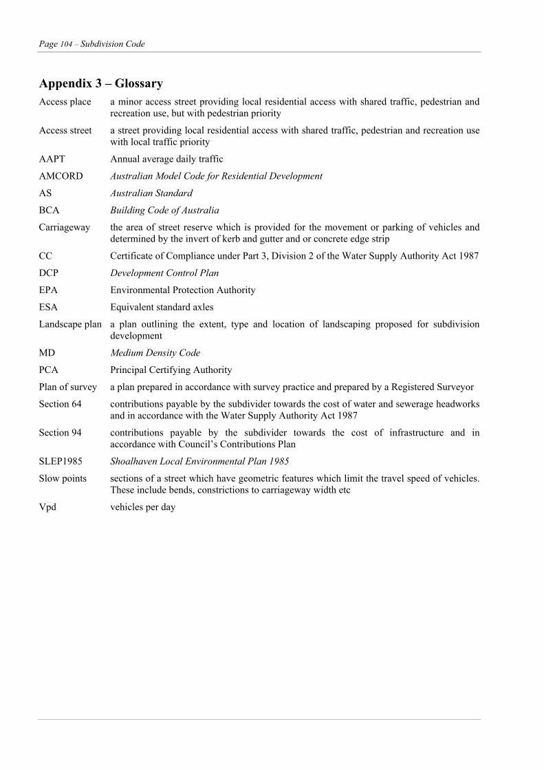
Page 104 – Subdivision Code
Appendix 3 – Glossary Access place a minor access street providing local residential access with shared traffic, pedestrian and
recreation use, but with pedestrian priority
Access street a street providing local residential access with shared traffic, pedestrian and recreation use with local traffic priority
AAPT Annual average daily traffic
AMCORD Australian Model Code for Residential Development
AS Australian Standard
BCA Building Code of Australia
Carriageway the area of street reserve which is provided for the movement or parking of vehicles and determined by the invert of kerb and gutter and or concrete edge strip
CC Certificate of Compliance under Part 3, Division 2 of the Water Supply Authority Act 1987
DCP Development Control Plan
EPA Environmental Protection Authority
ESA Equivalent standard axles
Landscape plan a plan outlining the extent, type and location of landscaping proposed for subdivision development
MD Medium Density Code
PCA Principal Certifying Authority
Plan of survey a plan prepared in accordance with survey practice and prepared by a Registered Surveyor
Section 64 contributions payable by the subdivider towards the cost of water and sewerage headworks and in accordance with the Water Supply Authority Act 1987
Section 94 contributions payable by the subdivider towards the cost of infrastructure and in accordance with Council’s Contributions Plan
SLEP1985 Shoalhaven Local Environmental Plan 1985
Slow points sections of a street which have geometric features which limit the travel speed of vehicles. These include bends, constrictions to carriageway width etc
Vpd vehicles per day

Subdivision Code – Page 105
Appendix 4 – Forms
Form 1 Work-as-Executed Plans Subdivision Engineering Works
1. GENERAL
a. In order to have a permanent record of construction which incorporates amendments, completed site regrading etc a certified Works-as-Executed plan is to be lodged for Council's records, with Work-as-Executed figures (where there is a variation from the design) shown on plan and longitudinal section.
b. Work-as-Executed Plans must be lodged to Subdivision Development Director.
c. A Subdivision Certificate will not be processed until the Work-as-Executed Plan or construction bond has been received and verified.
d. The Work-as-Executed Plan must be certified by the Registered Surveyor or Professional Civil Engineer responsible for the preparation of the Work-as-Executed Plan.
e. The Registered Surveyor responsible for the preparation of the Plan of Survey covering the subdivision is to supply a signed certificate stating that all pipes and associated pits are located wholly within the respective easements (Form 2).
f. The following certificate is to be appended to the plan and signed by the supervising surveyor or engineer:
"I hereby certify that engineering works shown on this plan have been constructed generally in accordance with the construction certificate approved by Shoalhaven City Council/Accredited Certifier."
Name: ...............................................................................
Signature: ...............................................................................
Capacity: ...............................................................................
Date: ...............................................................................
Page 106 – Subdivision Code
Appendix 4 – Forms (cont’d)
Form 2 Certificate of Compliance Example Certificate
Council Ref:
The General Manager Shoalhaven City Council PO BOX 42 NOWRA NSW 2541
Dear Sir,
Re: Subdivision of Lot The plan of survey bearing the above mentioned description and reference intends to create the following easements over the specified lots. Easement Description Burdened Lots 1. Easement to Drain Water over lots___________to__________ 1 metre wide 2. Easement to Drain Water over lots___________to__________ 2.5 metre wide Drainage pipes and associated structures are located in accordance with the approved plans and are laid wholly within the easement to be created by registration of the accompanying plan of survey.
Yours faithfully,
___________________________
Signature
___________________________
Name of Registered Surveyor
(Pls print)
Subdivision Code – Page 107
Restriction As To User The following are typical restrictions as to user under Section 88B of the Conveyancing Act which Council may impose as conditions of a development consent for subdivision. They are provided as a guide. Modification may be required to suit specific requirements.
Right of Way a) The maintenance of the Right of Carriageway shall be shared equally among the owners for the time
being of the lots benefited.
b) The cost of maintenance of the carriageway shall be borne by the registered proprietors of the lots benefited in the following proportions:
Lots XXX 50% each of the cost of that part of the carriageway as lies within Lot 1.
Lots XXX 25% each of the cost of that part of the carriageway as lies between the point where the road exits Lot 1 at the west and the western side of the principal point used for ingress and egress to Lot 2.
Lots XXX 33.3% each of the cost of that part of the carriageway as lies between western side of the principal point used for ingress and egress to Lot XXX aforesaid and the western side of the principal point used for ingress and egress to Lot XXX.
Lots XXX 50% each of the cost of that part of the carriageway as lies between the western side of the principal point used for ingress and egress to Lot 3 aforesaid and the principal residence on Lot XXX and if none, the point half way along the length of the carriageway within Lot XXX.
Lot XXX 100% of the cost of that part of the carriageway as lies between the principal residence on Lot XXX and if none, the point half way along the length of the carriageway within Lot XXX and the boundary of Lot XXX.
If at any time such owners cannot agree as to the need for or the cost of such maintenance then any one of them may serve upon the others a notice specifying the maintenance to be performed and its cost and if within fourteen days of service of that notice (which notice shall be in writing and served in accordance with Section 170 of the Conveyancing Act) the owners have not agreed to the performance of the maintenance specified in that notice then an engineer shall be appointed for purposes of deciding whether or not such maintenance is required and the cost of that maintenance.
If the owners of the said lots cannot agree upon the appointment of an engineer within the period of fourteen days from the expiry of the notice referred to above then the President for the time being of the Association of Consulting Engineers Australia shall be requested to appoint an engineer to report on the needs of such maintenance and its cost.
A certificate or report of the engineer appointed under this clause shall be conclusive and binding upon the owners of the said lots. The cost of such engineers report shall be borne by the part first serving the notice requiring maintenance work to be carried out if the report of the engineer is to the effect that such maintenance was not necessary otherwise the cost of such engineers report shall be borne equally among the owners for the time being of the lots benefited.
If the certificate or report of that engineer is to the effect that such maintenance is necessary then the party first serving the notice may arrange for such maintenance work to be carried out and the other owners shall each within fourteen days of being so requested contribute one (XXX) of the invoice cost of that work upon it being completed. If payment is not made within that time then the owner who has organised that work may pay for it and one XXX of the costs thereof shall be a debt owing by each of the other owners to that first owner.
Other options which may be included c) No registered proprietor of any lot benefited shall use, drive or permit to be used or driven any
vehicle exceeding 22 tonnes gross vehicular mass over the Right of Carriageway other than vehicles
Page 108 – Subdivision Code
used in the course of the construction of or maintenance of the surface of the carriageway or any buildings on any lot benefited or in connection with the agricultural use of any lot benefited.
d) Where it passes through Lot XXX DP XXX, both sides of the Right of Carriageway are to be fenced and maintained.
e) Only minimal tree clearing shall be carried out for the construction and maintenance of the Right of Carriageway.
Building Envelope a) No erection of buildings except within the hatched areas shown on the approved plans.
b) No dwelling shall be erected within 30 metres of any boundary of the lot burdened.
Building Colours a) No building shall be erected unless of darker external colour/materials, to blend with the landscape.
Any metal cladding roofing or water tank shall be pre-coloured at manufacturing stage.
Landscaping a) Any application for a building shall be accompanied by a landscape plan detailing landscaping to be
provided to reduce the visual impact of the building.
b) Any landscaping on all allotments shall include local native species.
c) The registered proprietor shall plant and maintain trees and shrubs within the area donated as “δ Easement for tree planting XXX wide” in the abovementioned plan.
Removal of Vegetation a) There shall be no removal or disturbance of indigenous native vegetation, on any allotment, including
canopy trees, understorey and ground cover vegetation, without the prior written consent of the Development and Environmental Services Director, except to maintain the existing building envelopes and access roads.
b) No trees are to be removed without obtaining development consent from the Development and Environmental Services Director.
c) No clearing of native vegetation except within building envelopes and/or bush fire protection zones.
Building Height a) No building erected on lots ** shall exceed 6.0 metres in height above existing natural ground level at
any point. Excluded shall be chimneys, vents, aerials and the like.
b) No building shall be constructed in a location such that the roofline projects above the adjacent natural ridgeline.
Bushfire a) No building to be constructed without being surrounded by a fuel free bushfire zone having a minimum
radius of *** metres and a fuel reduced zone beyond for a further *** metres. Trees may be retained within the fuel free zone where:
i) they do not overhang any building
ii) the tree canopy within this zone is not continuous (a ratio of approximately one tree per 220 square metres would be appropriate)
iii) the ground area is maintained as green well watered lawns within this zone;
iv) are not of a species that retain dead material or deposit excessive quantities of ground fuel in a short period;
v) the lower section of the trunk has any potential ground fuel removed; and
Subdivision Code – Page 109
vi) the planting of a fire retardant species would be encouraged within this zone and with the above constraints.
vii) Each building fire protection zone shall be placed such that they are totally located within each allotment.
b) No building shall be constructed unless provided with:-
i) A stored water facility dedicated to fire-fighting purposes in accordance with the recommendations of the NSW Rural Fire Service is to be provided. A minimum capacity of 10,000 litres shall be available at all times exclusively for fire fighting purposes. The dams on Lots *** may be used for the provision of water for fire fighting purposes.
ii) The provision of a petrol or diesel powered pump providing adequate pressure for fire-fighting purposes. This equipment must have a 38mm Stortz delivery coupling fitted to ensure compatibility with NSW Rural Fire Service fire fighting equipment.
Effluent Disposal a) No effluent disposal onsite except within the designated areas shown on the submitted plan and shall
only be by way of an aerated water treatment system. Wet weather storage areas shall be provided in accordance with the effluent disposal report prepared by ***.
b) No effluent disposal on site except where treated to a tertiary quality and applied by a spray or dripper irrigation to a filled, bunded and landscaped area of approximately XXX square metres in area. Wet weather storage may be required dependent on the size of future development.
c) No effluent disposal onsite except **.
d) No building shall be constructed unless effluent disposal is provided by way of an aerated system and for lots XXX are to be sited at a maximum distance from the adjacent creek.
Environmental a) No fencing to be erected within 20 metres of the road frontage, unless it is constructed of either post and
wire, post and rail, ti-tree fencing or cultivated hedges.
b) No erection of fencing within proposed allotments except boundary fences and which are to limit the removal of eucalyptus and casuarina trees to a one metre strip.
c) The keeping of domestic cats is prohibited on any allotment.
d) The keeping of domestic dogs on any allotment shall be subject to the following restrictions:
i) A maximum of two dogs can be kept on any allotment.
ii) No dogs of aggressive hunting ability shall be permitted (eg Rottweilers, Alsations, Pigdogs etc)
iii) Dogs shall be restrained within the building areas of each lot during the hours between sunset and sunrise each day by fencing/caging enclosures, leashing or physical restraint.
iv) Dogs shall be leashed or otherwise suitably restrained if they are taken outside any allotment during the day.
v) Dogs shall not be permitted to enter areas of indigenous vegetation or wetland areas on any allotment unless restrained.
e) All boundaries shall be fenced with a minimum of four strand plain wire, with the top wire and the bottom two wires consisting of non-electrified wire, and the bottom fence wire no closer than 40cm to the ground at any point.
Access a) No vehicular access to proposed lot XXX except at a point shown on the approved plans.
b) No vehicular access from XXX to lot(s) XXX.
Page 110 – Subdivision Code
c) No vehicular access from XXX to proposed lot(s) XXX except at the common boundaries between proposed lots XXX and proposed XXX.
Driveways – Rural a) No driveway shall be constructed to Lots XXX without the installation of a pipe culvert having a
minimum diameter of 375mm, with an effective length of 4.8 metres and associated headwalls.
b) No driveway shall be constructed to Lots XXX without the installation of a bitumen sealed/concrete/gravel driveway across the table drain and footpath being 4.8 metres wide at the concrete gutter crossing and in accordance with Councils Plan SC263234 XXX (A bitumen seated or concrete driveway to be specified if the existing public road is bitumen sealed. If the public road is gravel then the driveway is similarly constructed).
Floor Level a) No erection of habitable rooms on the proposed lots unless they have a minimum floor level 300mm
above the 1 in 100 year flood level determined at RL XXX AHD.
b) No erection of buildings on the proposed lots unless they have a minimum floor level 300mm above the 1 in 100 year flood level determined at RL XXX AHD.
Subdivision Code – Page 111
Bibliography
AMCORD Urban 1992
Victorian Code for Residential Development 1992
Armidale Residential Development Code 1996
ACT Code for Residential Development 1993
The Streets Where We Live, Stapleton 1984, Dept of Environmental and Planning, Traffic Authority NSW, Land Commission of NSW
Soil and Water Management for Urban Development, NSW Department of Housing 1993
Managing Urban Stormwater NSW Department of Housing 1998
Urban Erosion and Sediment Control, Department of Conservation and Land Management 1992
Guidelines for the Control of Erosion and Sedimentation in Roadworks, Roads and Traffic Authority 1984
Australian Rainfall and Runoff, Institution of Engineers Australia 1977 and 1987
Guidelines for Tree planting and Maintenance on Urban Roads, Roads and Traffic Authority of NSW 1987
Hazard Reduction for the Protection of Buildings in Bushland Areas, NSW Fire Brigades Board of Fire Commissioners of NSW 1984
Pollution Control Manual for Urban Stormwater, State Pollution Control Commission 1987
Design guidelines: Stormwater pollution control ponds and wetlands by Ian Lawrence and Peter Breen.
The Constructed Wetlands Manual Vol 1 and 2 Department of Land and Water Conservation NSW
Page 112 – Subdivision Code
Index Flood Studies, 49 AADT, 11 Floodways, 47 Acceptable Solutions, 3 floor levels, 47, 74 Access Place, 11, 24 Floor levels, 49 Access Street, 11, 24 footpath, 17 Accredited Certifier, 96
Allotment Layout, 54 Footpath, 24 Footpath Reserve, 84 appeal, 90 Gas, 45 Applications, 87 Geotechnical, 67 Approvals, 90 Heritage Act 1977, 87 Battle-axe lots, 55, 82 Industrial Subdivision, 82, 83 Bonding of Works, 97
Bridges, 49, 74 Inspections, 96 Insurance, 96 Building Code of Australia, bushfire, 78 Integrated Development, 88, 89 Bus routes, 18, 19
Bus Stop, 19 Integrated Development, 87 inter-allotment drainage, 48 Bushfire, 65, 78 Interallotment Drainage, 49 Carriageway, 11, 84 Intersections, 12 Certificate of Compliance, 44 Kerb and Gutter, 96 Clean Air Act 1961, 87 Kerb Return, 24 Clean Waters Act 1970, 87 Kerb Type, 24, 84 Clearing, 96 Land and Environment Court Act 1979, 87 Collector Street, 11, 24 Landscape, 75 Commercial Subdivision, 86 Landscape Plan, 52 Community Land Development Act 1989, 87 Laneways, 11, 24 Completion of Works, 98 legal access, 72 Compliance Certificate, 95, 96 Limited Access Roads, 31 Complying Development, 87 Local Distributor, 24 Construction Certificate, 91 Local Distributor Road, 11 Construction Safety Act, 91 Local Government Act 1993, 87 Construction Safety Act 1912, 87 Local Street, 11, 24 Contractors, 95 Longitudinal Grade, 24 Contributions, 90 Longitudinal gradients, 32 corner splays, 85 Low Density Residential, 58 Crossfall, 32 Maintenance Bond, 44 Culverts, 74 Maintenance of Works, 98 Curved alignment, 26 Medium Density Housing DCP No. 71, 1 Cyclist, 15 Naming of Roads, 98 Dam Safety Act 1975, 87 National Parks and Wildlife Act 1974, 87 DCP, 1 Noise Control Act 1975, 87 Design ESA, 40 Occupational Health and Safety Act 1983, 87 Design Speed, 25 On-street Parking, 33 Detention Basins, 49 Open Space, 20 Determination of Applications, 90 Parking, 24 Distributor Road Pavement Residential, 24
Drainage, 46, 47, 48, 49, 74 Construction, 96 Drainage Discharge, 49 Surfacing, 96 Driveway Access, 29 testing, 95
Pavement Design, 40, 41, 73 Dual Occupancy, 44 Easements, 49 Pavement Treatment, 24
Pedestrian, 15 Effluent Disposal, 81 Performance Criteria, 3 Electricity, 44, 81 Plans, 90 Electricity Supply, 44
Construction, 92 Engineering plans, 23 Contour, 93 Erosion Control Measures, 95 Erosion Control, 95 Fees and Charges, 90 Flood Prone Areas, 94 Fisheries Management Act 1994, 87
Subdivision Code – Page 113
Intersection, 92 Landscaping, 94 Preparation, 91 Residential Roadworks, 91 Road, 92 Rural road, 92 Scales, 93 Stormwater Drainage, 92 Water and Sewerage supply, 94 Work-as-Executed, 97
Pollution Control Act 1970, 87 Pram access, 40 Principal Certifying Authority, 91 Procedures, 87 Public Liability Insurance, 95 Request for Reconsideration, 90 Residential Allotments, 54, 55, 56, 57 right of way, 72 Rivers and Foreshores Improvement Act 1948, 87 Road Classification, 11, 73, 84 Road Reserve, 84 Roundabouts, 14 Rural driveways, 72 rural public roads, 72 Rural Road, 71 Rural Services, 80 Rural Subdivision, 69 Section 88B restrictions, 78 Section 94 Contributions, 1 service lane, 85 Service Road, 84 Sewerage, 44, 97 Shoalhaven Bicycle Strategy, 15 Site Analysis, 70 Site Analysis Urban, 4 Site Drainage, 48 Site regrading, 94 Site Regrading, 96 slow points, 26 Soil Conservation Act 1938, 87 solar access, 59
Staged Development, 45, 90 steel motor grid, 72 Stopping Distances, 30 Stormwater Drainage, 46, 47, 48
Major Systems, 46 Minor Systems, 46
Stormwater Quality Management, 50 Strata Subdivision, 68 Streepscape, 52, 53 Street Design, 23 Street Leg Length, 25 Street length, 26 Street parking, 39 Street Reserve, 24 Sub-Contractors, 95 Subdivision Certificate, 91, 97 Subdivision of Buildings, 68 Sub-grade, 96 super elevation, 32 Telephone, 45 Testing, 95 Threatened Species Conservation Act 1995, 87 T-junctions, 14 Traffic Study, 8 Transport, 18 Turning areas, 34, 35, 36, 37, 38 Urban Design, 6, 7 Utility Service Conduits, 96 Utility Services in Footways, 45 Variations to Approval, 91 Vehicle Parking, Industrial, 84 Verge Width, 24 Water and Sewer Mains, 96 Water pollution control ponds, 50 Water Supply, 44, 81, 97 Water Supply or Sewerage Cut-ins, 95 wetlands, 50 Wheelchair, 40 Work-as-Executed, 97 Workers Compensations, 91