subject: approval of amendment 7 to the pans-atm letter... · attachment a to state letter an...
TRANSCRIPT

999 Robert-Bourassa Boulevard
Montréal, Quebec
Canada H3C 5H7
Tel.: +1 514 954-8219-
Fax: +1 514 954-6077-
Email: [email protected]
www.icao.int
International
Civil Aviation
Organization
Organisation
de l’aviation civile
internationale
Organización
de Aviación Civil
Internacional
Международная
организация
гражданской
авиации
Tel.: +1 514-954-8219 ext. 6710
Ref.: AN 13/2.1-16/54 23 June 2016
Subject: Approval of Amendment 7 to the PANS-ATM
Action Required: a) Implementation of the amendment
on 10 November 20161; b) Publication of any differences
as of 10 November 2016
Sir/Madam,
I have the honour to inform you that the Air Navigation Commission, acting under 1.
delegated authority, on 1 March 2016, approved Amendment 7 (i.e. Amendments 7-A and 7-B) to the
fifteenth edition of the Procedures for Air Navigation Services — Air Traffic Management (PANS-ATM,
Doc 4444), for applicability on 10 November 20162. The amendments were approved on 6 June 2016 by
the President of the Council on behalf of the Council in accordance with established procedure. Copies of
the amendment are available as attachments to the electronic version of this State letter on the ICAO-NET
(http://portal.icao.int) where you can access all other relevant documentation.
Amendment 7 (i.e. Amendments 7-A and 7-B) stems from proposals developed by the 2.
Separation and Airspace Safety Panel (SASP), the second meeting of the Operational Data Link Panel
(OPLINKP/2), the third meeting of the Air Traffic Management Operation Panel (ATMOPSP/3), the first
meeting of the Flight Operations Panel (FLTOPSP/1), the sixteenth meeting of the Operations Panel
Working Group of the Whole (OPSP/WG/WHL/16), the third meeting of the Aerodromes Panel (AP/3)
and the Meteorology (MET) Divisional Meeting (2014). The amendment is related to:
a) performance-based longitudinal and lateral separation minima and automatic
dependent surveillance — contract (ADS-C) climb and descend procedure (CDP);
b) separation departing aircraft from arriving aircraft that are following an area
navigation (RNAV) or required navigation performance (RNP) route;
1 5 November 2020 for Amendment 7-B related to an enhanced global reporting format in terms of implementation and
publication of differences. 2 5 November 2020 for Amendment 7-B related to an enhanced global reporting format.

- 2 -
c) data link initiation capability (DLIC), ADS-C, performance-based communication
and surveillance (PBCS) and satellite voice communications (SATVOICE);
d) vectoring for final approach, advising of take-off run available (TORA) and use of
SID/STAR;
e) standard phraseology for de/anti-icing ground and flight crews;
f) emergency descent procedures;
g) autonomous runway incursion warning system (ARIWS);
h) forwarding of special air-reports and definition of SIGMET information; and
i) an enhanced global reporting format for assessing and reporting runway surface
conditions (2020 applicability).
An implementation task list, including an outline of guidance material, and an impact 3.
assessment for the amendment are presented in Attachments B and C, respectively.
Your Government is invited by the Council to implement the provisions of the 4.
PANS-ATM as amended. In this connection, I draw your attention to the decision taken by the Council,
on 1 October 1973, to discontinue the publication of differences in Supplements to the PANS documents
and, instead, to request States to publish up-to-date lists of significant differences from PANS documents
in their Aeronautical Information Publications (AIPs).
Please note that the time between the approved date and the applicability date of 5.
5 November 2020 for Amendment 7-B to the PANS-ATM is longer than usual due to the
multidisciplinary nature of the proposal and the resulting need for distributing an information package as
part of a roll-out plan to ensure that all disciplines are aligned towards a seamless implementation.
May I, therefore, invite your Government to publish in your Aeronautical Information 6.
Publication a list of any significant differences which will exist on 10 November 20163 between the
amended provisions of the PANS-ATM and your national regulations and practices.
Accept, Sir/Madam, the assurances of my highest consideration.
Fang Liu
Secretary General
Enclosures:
A — Amendment to the Foreword of the PANS-ATM
B — Implementation task list and outline of guidance material in
relation to Amendment 7 to the PANS-ATM
C — Impact assessment in relation to Amendment 7 to the
PANS-ATM
3 5 November 2020 for Amendment 7-B related to an enhanced global reporting format.

ATTACHMENT A to State letter AN 13/2.1-16/54
AMENDMENT TO THE FOREWORD OF THE
PANS-ATM, FIFTEENTH EDITION
Add the following at the end of Table A:
Amendment Source(s) Subject Approved
Applicable
7-A The Separation and
Airspace Safety Panel
(SASP), the second
meeting of the Operational
Data Link Panel
(OPLINKP/2), the third
meeting of the Air Traffic
Management Operation
Panel (ATMOPSP/3) and
the Secretariat, the first
meeting of the Flight
Operations Panel
(FLTOPSP/1), the sixteenth
meeting of the Operations
Panel Working Group of
the Whole
(OPSP/WG/WHL/16), the
third meeting of the
Aerodromes Panel (AP/3)
and the Meteorology
(MET) Divisional Meeting
(2014).
Performance-based longitudinal and
lateral separation minima and ADS-C
CDP; separation between arrival and
departure operations; DLIC, CPDLC,
ADS-C, PBCS and SATVOICE;
procedures used to vector for final
approach, advising of TORA and
SID/STAR; standard phraseology for
de/anti-icing ground and flight crews;
emergency descent procedures;
autonomous runway incursion
warning system (ARIWS); and
forwarding of special air-reports and
definition of SIGMET information.
6 June 2016
10 November 2016
Amendment Source(s) Subject Approved
Applicable
7-B The third meeting of the
Aerodromes Panel (AP/3)
The use of a global reporting format
for assessing and reporting runway
surface conditions
6 June 2016
5 November 2020


ATTACHMENT B to State letter AN 13/2.1-16/54
IMPLEMENTATION TASK LIST AND OUTLINE OF GUIDANCE
MATERIAL IN RELATION TO AMENDMENT 7 TO PANS-ATM
(DOC 4444)
1. IMPLEMENTATION TASK LIST
1.1 Essential steps to be followed by a State in order to implement Amendment 7 to the
PANS-ATM:
a) conduct a gap analysis between the amendment and national regulatory framework;
b) identification of the rule-making process necessary to transpose the amendment
concerning the following subjects into the national requirements, where necessary;
c) drafting of the modification to the national requirements and means of compliance;
d) official adoption of the national requirements and means of compliance;
e) identification and publication of significant differences, if any, in the State’s
aeronautical information publication (AIP);
f) modification of surveillance programmes to include new requirements, if applicable;
g) revision of guidance material and checklists for safety oversight inspectors;
h) training of inspectors based on the revised inspector guidance material; and
i) ensure compliance by industry (air navigation services provider (ANSP) and
operator) through safety oversight activities.
2. STANDARDIZATION PROCESS
2.1 Approval date: May 2016
2.2 Applicability date: 10 November 2016 for the elements concerning performance-based
longitudinal and lateral separation minima and automatic dependent surveillance — contract (ADS-C)
climb and descend procedure (CDP); separation between arrival and departure operations; data link
initiation capability (DLIC), controller-pilot data link communications (CPDLC), automatic dependent
surveillance — contract (ADS-C), performance-based communication and surveillance (PBCS) and
satellite voice communications (SATVOICE); procedures used to vector for final approach, advising
of take-off run available (TORA) and standard instrument departures (SID) and standard instrument
arrivals (STAR) (SID/STAR); standard phraseology for de/anti-icing ground and flight crews; emergency
descent procedures; autonomous runway incursion warning system (ARIWS); and forwarding of special
air-reports and definition of SIGMET information.
2.3 Applicability date: 5 November 2020 for the element concerning the use of a global
reporting format for assessing and reporting runway surface conditions.
2.4 Embedded applicability date(s): N/A

B-2
3. SUPPORING DOCUMENTATION
3.1 ICAO documentation
Title Type (PANS/TI/Manual/Circ)
Planned
publication date
Performance-based Communication and
Surveillance Manual (Doc 9869)
Manual November 2016
Global Operational Data Link (GOLD)
Manual (Doc 10037)
Manual
November 2016
Satellite Voice Operations Manual (SVOM)
(Doc 10038)
Manual November 2016
Guidelines for the Implementation of Lateral
Separation Minima Circular (Cir 341-AN/184)
Circular Available
Automatic Dependent Surveillance — Contract
(ADS-C) Climb and Descend Procedure (CDP)
Circular (Cir 342-AN/200)
Circular Available
Guidelines for the Implementation of
Performance-based Longitudinal Separation
Minima Circular (Cir 343-AN/201)
Circular November 2016
3.2 External documentation
Title
External
Organization Publication date
None
4. IMPLEMENTATION ASSISTANCE TASKS
Type Global Regional
Regional
workshop as
resources permit
ICAO regional offices or States
offering to host regional events
5. UNIVERSAL SAFETY OVERSIGHT AUDIT
PROGRAMME (USOAP)
5.1 No major changes to the USOAP CMA protocol questions are envisaged. However, in
the area of ANS, existing protocol questions may need amendment or new protocol questions may be
required to assess effective implementation by States. This will be assessed during the next amendment
cycle of the protocol questions.
— — — — — — — —
ATTACHMENT C to State letter AN 13/2.1-16/54
IMPACT ASSESSMENT IN RELATION
TO AMENDMENT 7 TO PANS-ATM (DOC 4444)
1. INTRODUCTION
1.1 Amendment 7 to the PANS-ATM is intended to address the requirements and procedures
for the following:
a) performance-based longitudinal and lateral separation minima for aircraft in the
en-route phase of flight and ADS-C CDP;
b) separation of departing aircraft from arriving aircraft that are following an RNAV or
RNP route;
c) use of DLIC, CPDLC, ADS-C, PBCS and SATVOICE;
d) vectoring for final approach, use of TORA and SID/STAR;
e) standard phraseology for de/anti-icing ground and flight crews;
f) emergency descent;
g) use of ARIWS;
h) forwarding of special air-reports and definition of SIGMET information; and
i) use of an enhanced global reporting format for assessing and reporting runway
surface conditions.
2. IMPACT ASSESSMENT
Amendment concerning performance-based longitudinal and lateral
separation minima and ADS-C CDP
2.1 Safety impact: Positive — This new separation minima increases flexibility in air traffic
management and is contingent on required communication performance (RCP) and required surveillance
performance (RSP) which increases robustness and safety of data link operations.
2.2 Financial impact: Negligible — The financial impact is considered negligible for both
State and industry if effective processes and procedures, necessary ground system automation and
monitoring programmes are already in place. However, should those not be in place and the ANSPs wish
to implement the procedure(s), associated implementation costs will only be incurred when the air traffic
demand requires reduction in separation minima. This will provide for increased access to optimal flight
levels, resulting in increased efficiency and fuel savings.

C-2
2.3 Security impact: No security impact is expected.
2.4 Environmental impact: Positive — Subject to traffic demand, the implementation of the
new separation standards will facilitate increased availability of optimal flight levels, with a consequent
reduction of emissions.
2.5 Efficiency impact: Positive — Subject to traffic demand, the implementation of the new
separation standards will facilitate increased availability of optimal flight levels, with a consequent
increase in efficiency.
2.6 Expected implementation time: One to two years — The new separation Standards will be
implemented only when air traffic density necessitates a reduction in separation minima. If effective
processes and procedures and necessary ground automation and monitoring programmes are already in
place, it is anticipated that a shorter timeline will suffice. However, should those not be in place and
ANSPs wish to implement, the implementation time will extend.
Amendment concerning separation between arrival and departure
operations
2.7 Safety impact: Positive — This amendment provides an additional separation method for
controllers to use in situations where none currently exist in the PANS-ATM. This change will therefore
make airspace management easier and is, as a consequence, expected to inherently result in improved
safety in the airspace. By defining where and when the aircraft should be before another aircraft is cleared
to take-off, it is expected that the conflicts between arrivals and departures will be reduced with a
consequent increase in the safety of operation.
2.8 Financial impact: Negligible — There will be a nominal cost to States, associated with
the rule-making process necessary to transpose the modified ICAO provisions into national regulations.
For industry, the cost incurred by the amendment will involve an analysis of departure and arrival tracks
to determine the waypoint positions to ensure the necessary separation, which is already embedded in the
exercise of their functions as procedure designers and/or airspace managers.
2.9 Security impact: No security impact is expected.
2.10 Environmental impact: Positive — With the reduction in waiting time to take-off,
greenhouse gas emissions by aircraft on the ground will be reduced.
2.11 Efficiency impact: Positive — With the definition of points in the arrival and/or approach
procedures, efficiency of operations are expected to increase with reduction in waiting time to take-off
which will reduce fuel burn on the ground.
2.12 Expected implementation time: One year — To take advantage of the new departure vs
arrival separation standards, the currently published departure and arrival procedures will need to be
analysed to determine the waypoint positions to guarantee the necessary separation. From that point on,
during the development of any applicable new procedures, procedure designers will conduct such an
analysis as an integral part of their work. This ongoing development will therefore be coincident with the
State performance-based navigation (PBN) implementation plan.

C-3
Amendment concerning DLIC, CPDLC, ADS-C, PBCS and
SATVOICE
2.13 Safety impact: Positive — Clarification on terms and existing provisions regarding data
link (DLIC, CPDLC and ADS-C) brought by this amendment will have a positive safety impact in
particular for operations in oceanic and remote areas. The amendment regarding PBCS will also have a
positive safety impact since ANSPs will be able to identify eligible aircraft to which reduced separation
minima can be safely applied based on communication and surveillance capabilities filed in the flight
plan. No safety impact is expected for the SATVOICE amendment.
2.14 Financial impact: Negligible to significant — No significant financial impact is expected
for States but the financial impact for industry will vary, from nominal to significant, depending on the
level of data link and PBCS implementation. Concerning the SATVOICE amendment, no significant
financial impact is expected.
2.15 Security impact: Neutral — No security impact is expected.
2.16 Environmental impact: Neutral — No environmental impact is expected.
2.17 Efficiency impact: Positive — The amendment supports the implementation of data link,
PBCS and SATVOICE, which enables more flexible use of airspace.
2.18 Expected implementation time: One to two years — Most changes are to clarify the terms
and streamline existing provisions except those related to PBCS, which may require adaptation of the
flight plan filing and processing system.
Amendment concerning procedures used to vector for final approach,
advising of TORA and SID/STAR
2.19 Safety impact: Positive — This amendment will enhance the comprehensibility as well as
the consistency of procedures, which will enable air traffic controllers and flight crews to have a common
understanding of the terms and expectations.
2.20 Financial impact: Negligible — This amendment is largely procedural in nature and it is
not expected that States would require any investment in systems or equipment. To prepare for
implementation, there will be a need to share information, and training will be required to acquaint the air
traffic controllers and flight crews with the new procedures.
2.21 Security impact: Neutral — No security impact is expected.
2.22 Environmental impact: Positive — The amendment, especially in regard to vectors for
final, will have a positive environmental impact as it removes the implied requirement for aircraft to be
established in level flight prior to intercepting the glide path thereby facilitating continuous descent and
reducing aircraft noise and fuel burn.
2.23 Efficiency impact: Positive — There will be a reduction of workload for both air traffic
controllers and flight crews with the removal of the requirement for flight crews to report when the
aircraft has intercepted the final approach track. The other facet would be increased efficiency through
reduced track miles.
C-4
2.24 Expected implementation time: One year —This amendment pertains only to operational
procedures. It is envisaged that air traffic controllers and flight crews should be able to use the new
procedures soon after they are allowed to do so.
Amendment concerning standard phraseology for de/anti-icing ground
and flight crews
2.25 Safety impact: Positive — The amendment improves the procedures for required
coordination between flight crew and ground de/anti-icing operations.
2.26 Financial impact: Negligible — The financial impact is considered neutral for States and
minimal for industry. The amendment is largely procedural in nature, so it would not require modification
to a State’s current legal or regulatory framework and would not require any investment in systems or
equipment. It is expected that industry would incorporate this amendment in the recurrent winter
operations training.
2.27 Security impact: No security impact is expected.
2.28 Environmental impact: Positive — Better coordination between flight crew and
de-icing/anti-icing ground crew will result in more efficient use of de-icing fluids and less waste.
2.29 Efficiency impact: Positive — Better coordination between flight crew and
de-icing/anti-icing ground crew will result in more efficient use of de-icing fluids and less waste.
2.30 Expected implementation time: One year — ICAO is working closely with SAE to
incorporate the content of this amendment in their documents. This will allow for wide industry adoption.
Amendment concerning emergency descent procedures
2.31 Safety impact: Positive — It removes uncertainty for air traffic controllers when an
aircraft is executing an emergency descent, especially in congested airspace.
2.32 Financial impact: Negligible — The financial impact is considered neutral for States and
minimal for industry. The amendment is largely procedural in nature, so it would not require modification
to a State’s current legal or regulatory framework and would not require any investment in systems or
equipment. It is expected that industry would incorporate this amendment in recurrent training.
2.33 Security impact: No security impact is expected.
2.34 Environmental impact: No environmental impact is expected.
2.35 Efficiency impact: No efficiency impact is expected.
2.36 Expected implementation time: One year — It is envisaged that air traffic controllers and
flight crews will become familiar with these procedures during their recurrent training.
C-5
Amendment concerning autonomous runway incursion warning
system (ARIWS)
2.37 Safety impact: Positive — The ARIWS concept has been designed for reduction of the
prevalence and consequences of runway incursions for specific cases where it is decided to implement.
2.38 Financial impact: The present cost of implementing an ARIWS is large but limited to a
small amount of aerodromes where it is needed. It will be justified by the local assessment. The
amendment to the PANS-ATM will only be applicable when the ARIWS is installed and used. The
financial impact as a result of this amendment is considered negligible for States and industry. There will
be a nominal cost to States, associated with the State rule-making process necessary to transpose the
modified ICAO provisions into the national regulations. There will be minimal cost to industry,
predominantly related to training of air traffic controllers and flight crews with respect to the operational
procedures to use the ARIWS.
2.39 Security impact: No security impact is expected.
2.40 Environmental impact: No environmental impact is expected.
2.41 Efficiency impact: ARIWS provisions have been developed to minimize the impact on
normal operations.
2.42 Expected implementation time: One year — The expected implementation tasks are
primarily related to training air traffic controllers and flight crews with respect to the operational
procedures to use the ARIWS.
Amendment concerning forwarding of special air-reports and
definition of SIGMET information
2.43 Safety impact: No safety impact is expected.
2.44 Financial impact: No significant financial impact is expected.
2.45 Security impact: No security impact is expected.
2.46 Environmental impact: No environmental impact is expected.
2.47 Efficiency impact: Positive — Greater efficiency can be expected through the exchange
of the special air-reports through the aeronautical fixed service (AFS) Internet-based services.
2.48 Expected implementation time: One year — The expected implementation tasks are
primarily related to a slight adjustment of the means employed by ATS units and their operating
procedures for forwarding special air-reports.
Amendment concerning use of an enhanced global reporting format
for assessing and reporting runway surface conditions
(2020 applicability)
2.49 Safety impact: Positive — The amendment will contribute to a reduction in runway
excursion incidents/accidents by ensuring that runway surface conditions are reported in a standardized

C-6
manner, which will enable flight crews to accurately determine aeroplane take-off and landing
performance.
2.50 Financial impact: Minimal — There will be a nominal cost to States, associated with the
State rule-making process necessary to transpose the modified ICAO provisions into the national
regulations. It is anticipated that there will be minimal cost to industry, predominantly related to training
of air traffic controllers and flight crew with respect to the phraseologies.
2.51 Security impact: No security impact is expected.
2.52 Environmental impact: Positive — Due to fewer occurrences of runway excursion
incidents and accidents.
2.53 Efficiency impact: Positive — Accurate and timely runway state information
disseminated according to defined terminology and procedures will have a positive impact on the
efficiency of the air transportation system. Occurrences of excursions, disruptions to aerodrome and air
traffic operations such as, but not limited to, the removal of aircraft disabled at an aerodrome, in particular
on a runway, are expected to be reduced.
2.54 Expected implementation time: One year — The expected implementation tasks are
primarily related to training air traffic controllers and flight crews with respect the addition and alignment
of phraseologies to the global reporting format for runway surface friction reporting. It should be noted
that it is essential that these changes are made in close coordination with those to Annex 14 —
Aerodromes, Volume I — Aerodrome Design and Operations and Annex 15 — Aeronautical Information
Services in connection with the introduction of the global reporting format, and that this may affect the
implementation date.
— END —

AMENDMENT No. 7-A
TO THE
PROCEDURES
FOR
AIR NAVIGATION SERVICES
AIR TRAFFIC MANAGEMENT
(Doc 4444)
INTERIM EDITION
The text of Amendment No. 7-A to the PANS-ATM (Doc 4444) was
approved by the President of the Council of ICAO on behalf of the Council
on 6 June 2016 for applicability on 10 November 2016. This interim edition
is distributed to facilitate implementation of the amendment by States.
Replacement pages incorporating Amendment No. 7-A are expected to be
distributed in October 2016. (State letter AN 13/2.1-16/54 refers.)
June 2016
INTERNATIONAL CIVIL AVIATION ORGANIZATION

2
NOTES ON THE EDITORIAL PRESENTATION
OF THE AMENDMENT 7-A TO THE PANS-ATM
The text of the amendment is arranged to show deleted text with a line through it and new text
highlighted with grey shading, as shown below:
1. Text to be deleted is shown with a line through it. text to be deleted
2. New text to be inserted is highlighted with grey shading. new text to be inserted
3. Text to be deleted is shown with a line through it
followed by the replacement text which is highlighted
with grey shading.
new text to replace existing text
3
TEXT OF AMENDMENT 7-A TO THE
PROCEDURES FOR AIR NAVIGATION SERVICES
AIR TRAFFIC MANAGEMENT
. . .
Chapter 1
DEFINITIONS
. . .
CPDLC message. Information exchanged between an airborne system and its ground counterpart. A
CPDLC message consists of a single message element or a combination of message elements
conveyed in a single transmission by the initiator.
CPDLC message set. A list of standard message elements and free text message elements
. . .
Downstream data authority. A designated ground system, different from the current data authority through
which the pilot can contact an appropriate ATC unit for the purposes of receiving a downstream
clearance.
. . .
Free text message element. Part of aA message element used to convey information not conforming that
does not conform to any standardized standard message element in the CPDLC message set in the
PANS-ATM (Doc 4444).
. . .
Logon address. A specified code used for data link logon to an ATS unit.
. . .
Performance-based communication (PBC). Communication based on performance specifications applied to
the provision of air traffic services.
Note.— An RCP specification includes communication performance requirements that are allocated to
system components in terms of the communication to be provided and associated transaction time,
continuity, availability, integrity, safety and functionality needed for the proposed operation in the context of
a particular airspace concept.
Performance-based navigation (PBN). Area navigation based on performance requirements for aircraft
operating along an ATS route, on an instrument approach procedure or in a designated airspace.

4
Note.— Performance requirements are expressed in navigation specifications (RNAV specification, RNP
specification) in terms of accuracy, integrity, continuity, availability and functionality needed for the
proposed operation in the context of a particular airspace concept.
. . .
Performance-based surveillance (PBS). Surveillance based on performance specifications applied to the
provision of air traffic services.
Note.— An RSP specification includes surveillance performance requirements that are allocated to
system components in terms of the surveillance to be provided and associated data delivery time, continuity,
availability, integrity, accuracy of the surveillance data, safety and functionality needed for the proposed
operation in the context of a particular airspace concept.
. . .
Preformatted free text message element. A free text message element that is stored within the aircraft
system or ground system for selection.
. . .
RCP type. A label (e.g. RCP 240) that represents the values assigned to RCP parameters for communication
transaction time, continuity, availability and integrity.
. . .
Required communication performance (RCP) specification. A statement of the performance requirements
for operational communication in support of specific ATM functions. A set of requirements for air
traffic service provision and associated ground equipment, aircraft capability, and operations needed to
support performance-based communication.
Required surveillance performance (RSP) specification. A set of requirements for air traffic service
provision and associated ground equipment, aircraft capability, and operations needed to support
performance-based surveillance.
. . .
SIGMET information. Information issued by a meteorological watch office concerning the occurrence or
expected occurrence of specified en-route weather phenomena which and other phenomena in the
atmosphere that may affect the safety of aircraft operations.
. . .
Standardized free text message element. A message element that uses a defined free text message format,
using specific words in a specific order.
Note.— Standardized free text message elements may be manually entered by the user or preformatted.
Standard message element. Part of a message defined in the PANS-ATM (Doc 4444) in terms of display
format, intended use and attributes.

5
. . .
Chapter 4
GENERAL PROVISIONS FOR AIR TRAFFIC SERVICES
. . .
4.4 FLIGHT PLAN
. . .
4.4.1 Flight plan form
. . .
4.4.1.4 An operator shall, prior to departure:
a) ensure that, where the flight is intended to operate on a route or in an area where an RNP type a
navigation specification is prescribed, the aircraft it has an appropriate RNP approval, and that all
conditions applying to that approval will be satisfied;
b) ensure that, where operation in reduced vertical separation minimum (RVSM) airspace is planned,
the aircraftit has the required RVSM approval; and
c) ensure that, where the flight is intended to operate where an RCP type specification is prescribed,
the aircraft has it has an appropriate RCP approval, and that all conditions applying to that approval
will be satisfied; and.
d) ensure that, where the flight is intended to operate where an RSP specification is prescribed, it has
an appropriate RSP approval, and that all conditions applying to that approval will be satisfied.
. . .
4.5.7 Description of air traffic control clearances
. . .
4.5.7.2 ROUTE OF FLIGHT
4.5.7.2.1 The route of flight shall be detailed in each clearance when deemed necessary. The phrase
“cleared via flight planned route” may be used to describe any route or portion thereof, provided the route or
portion thereof is identical to that filed in the flight plan and sufficient routing details are given to definitely
establish the aircraft on its route. The phrases “cleared via (designation) departure” or “cleared via
(designation) arrival” may be used when standard departure or arrival routes have been established by the
appropriate ATS authority and published in Aeronautical Information Publications (AIPs).
Note.— See 6.3.2.3 pertaining to standard clearances for departing aircraft and 6.5.2.3 pertaining to
standard clearances for arriving aircraft.
4.5.7.2.2 The phrase “cleared via flight planned route” shall not be used when granting a re-clearance.

6
. . .
4.6 HORIZONTAL SPEED CONTROL INSTRUCTIONS
4.6.1 General
4.6.1.1 In order to facilitate a safe and orderly flow of traffic, aircraft may, subject to conditions
specified by the appropriate authority, be instructed to adjust speed in a specified manner. Flight crews
should be given adequate notice of planned speed control.
Note 1.— Application of speed control over a long period of time may affect aircraft fuel reserves.
Note 2.— Provisions concerning longitudinal separation using the Mach number technique are
contained in Chapter 5, Separation Methods and Minima.
4.6.1.2 Speed control instructions shall remain in effect unless explicitly cancelled or amended by
the controller.
Note.— Cancellation of any speed control instruction does not relieve the flight crew of compliance
with speed limitations associated with airspace classifications as specified in Annex 11 — Air Traffic
Services, Appendix 4.
4.6.1.23 Speed control shall not be applied to aircraft entering or established in a holding pattern.
4.6.1.34 Speed adjustments should be limited to those necessary to establish and/or maintain a desired
separation minimum or spacing. Instructions involving frequent changes of speed, including alternate speed
increases and decreases, should be avoided.
4.6.1.45 The flight crew shall inform the ATC unit concerned if at any time they are unable to comply
with a speed instruction. In such cases, the controller shall apply an alternative method to achieve the desired
spacing between the aircraft concerned.
4.6.1.56 At levels at or above 7 600 m (FL 250), speed adjustments should be expressed in multiples of
0.01 Mach; at levels below 7 600 m (FL 250), speed adjustments should be expressed in multiples of
20 km/h (10 kt) based on indicated airspeed (IAS).
Note 1.— Mach 0.01 equals approximately 11 km/h (6 kt) IAS at higher flight levels.
Note 2.— When an aircraft is heavily loaded and at a high level, its ability to change speed may, in
cases, be very limited.
4.6.1.67 Aircraft shall be advised when a speed control restriction is no longer required.
. . .
4.6.4 SID and STAR
The flight crew shall comply with published SID and STAR speed restrictions unless the restrictions are

7
explicitly cancelled or amended by the controller.
Note 1.— Some SID and STAR speed restrictions ensure containment with RNAV departure or arrival
procedure (e.g. maximum speed associated with a constant radius arc to a fix (RF) leg).
Note 2.— See 6.3.2.4 pertaining to clearances on a SID and 6.5.2.4 pertaining to clearances on a STAR.
. . .
4.11 POSITION REPORTING
. . .
4.11.5 Contents of ADS-C reports
4.11.5.1 ADS-C reports shall be composed of data blocks selected from the following:
a) Aircraft identification
b) Basic ADS-C latitude longitude altitude time figure of merit
Note.— The basic ADS-C block is mandatory and is included in all ADS-C reports.
. . .
f) Meteorological information wind speed wind direction wind quality flag (if available) temperature turbulence (if available) humidity (if available)
Note.— The specifications for the elements in the meteorological information data block, including
their ranges and resolutions, are shown in Appendix 4 to Annex 3.
. . .
h) Extended projected profile (in response to an interrogation from the ground system) next waypoint estimated altitude at next waypoint estimated time at next waypoint (next + 1) waypoint estimated altitude at (next + 1) waypoint estimated time at (next + 1) waypoint (next + 2) waypoint

8
estimated altitude at (next + 2) waypoint estimated time at (next + 2) waypoint [repeated for up to (next + 128) waypoints] Note. — The specifications for the elements in the meteorological information data block, including
their ranges and resolutions, are shown in Appendix 4 to Annex 3.
. . .
4.12.6 Forwarding of meteorological information
. . .
4.12.6.2 When receiving special air-reports by data link communications, air traffic services units
shall forward them without delay to their associated meteorological watch office, and the WAFCs, and the
centres designated by regional air navigation agreement for the operation of aeronautical fixed service
Internet-based services.
. . .
4.15 DATA LINK COMMUNICATIONS INITIATION PROCEDURES
4.15.1 General
Note 1.— Provisions concerning the data link initiation capability (DLIC) are contained in Annex 10,
Volume II, Chapter 8.
Note 2.— Guidance material relating to the implementation of DLIC can be found in the Global
Operational Data Link (GOLD) Manual (Doc 10037).
4.15.1.1 Before entering an airspace where data link applications are required used by the ATS unit,
data link communications shall be initiated between the aircraft and the ATS unit in order to register the
aircraft and, when necessary, allow the start of a data link application. This shall be initiated by the aircraft,
either automatically or by the pilot, or by the ATS unit on address forwarding.
Note.— Guidance material relating to the data link initiation capability (DLIC) can be found in the
Manual of Air Traffic Services Data Link Applications (Doc 9694) ).
4.15.1.2 The DLIC logon address associated with an ATS unit shall be published in Aeronautical
Information Publications in accordance with Annex 15.
Note.— A given FIR may have multiple DLIC logon addresses; and more than one FIR may share the
same DLIC logon address.
4.15.2 Aircraft initiation
Whenever the pilot or the aircraft initiates data link communication procedures, an initiation message shall
be sent. Except when the initiation message is corrupted, it shall not be rejected by the ATS unit. On receipt
of a valid data link initiation request from an aircraft approaching or within a data link service area, the ATS
unit shall accept the request and, if able to correlate it with a flight plan, shall establish a connection with the
aircraft.
9
. . .
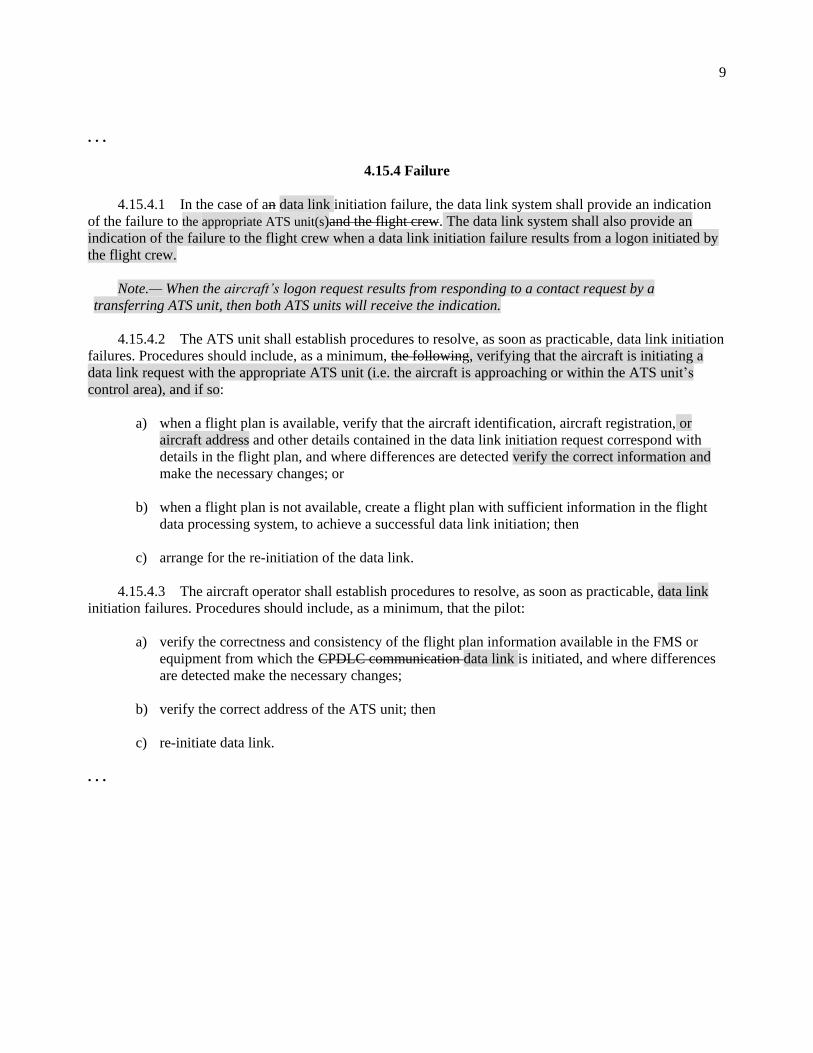
4.15.4 Failure
4.15.4.1 In the case of an data link initiation failure, the data link system shall provide an indication
of the failure to the appropriate ATS unit(s)and the flight crew. The data link system shall also provide an
indication of the failure to the flight crew when a data link initiation failure results from a logon initiated by
the flight crew.
Note.— When the aircraft’s logon request results from responding to a contact request by a
transferring ATS unit, then both ATS units will receive the indication.
4.15.4.2 The ATS unit shall establish procedures to resolve, as soon as practicable, data link initiation
failures. Procedures should include, as a minimum, the following, verifying that the aircraft is initiating a
data link request with the appropriate ATS unit (i.e. the aircraft is approaching or within the ATS unit’s
control area), and if so:
a) when a flight plan is available, verify that the aircraft identification, aircraft registration, or
aircraft address and other details contained in the data link initiation request correspond with
details in the flight plan, and where differences are detected verify the correct information and
make the necessary changes; or
b) when a flight plan is not available, create a flight plan with sufficient information in the flight
data processing system, to achieve a successful data link initiation; then
c) arrange for the re-initiation of the data link.
4.15.4.3 The aircraft operator shall establish procedures to resolve, as soon as practicable, data link
initiation failures. Procedures should include, as a minimum, that the pilot:
a) verify the correctness and consistency of the flight plan information available in the FMS or
equipment from which the CPDLC communication data link is initiated, and where differences
are detected make the necessary changes;
b) verify the correct address of the ATS unit; then
c) re-initiate data link.
. . .

10
Chapter 5
SEPARATION METHODS AND MINIMA
5.1 INTRODUCTION
. . .
Note 3.— Attention is drawn to the use of strategic lateral offset procedures (SLOP) described in
Chapter 16, 16.5.
Note 4.— Procedures applicable to data link initiation capability (DLIC) are contained in
Chapter 4. Procedures applicable to automatic dependent surveillance - contract (ADS-C) are contained in
Chapter 13. Procedures applicable to controller-pilot data link communications (CPDLC) are contained in
Chapter 14.
. . .
5.4.1 Lateral separation
. . .
5.4.1.2 LATERAL SEPARATION CRITERIA AND MINIMA
5.4.1.2.1 Means by which lateral separation may be applied include the following:
. . .
5.4.1.2.1.6 Lateral separation of aircraft on parallel or non-intersecting tracks or ATS routes.
Within designated airspace or on designated routes, lateral separation between aircraft operating on parallel
or non-intersecting tracks or ATS routes shall be established in accordance with the following:
a) for a minimum spacing between tracks of 93 km (50 NM) a navigational performance of RNAV 10
(RNP 10), RNP 4 or RNP 2 shall be prescribed;
b) for a minimum spacing between tracks of 55.542.6 km (3023 NM) a navigational performance of
RNP 4 or RNP 2 shall be prescribed. The communication system shall satisfy required communication performance 240 (RCP 240) and the surveillance system shall satisfy required surveillance performance 180 (RSP 180). Conformance monitoring shall be ensured by establishing an ADS-C event contract with a lateral deviation change event with a maximum of 5 NM threshold and a waypoint change event;
c) for a minimum spacing between tracks of 27.8 km (15 NM) a navigational performance of RNP 2 or
a GNSS equipage shall be prescribed. Direct controller-pilot VHF voice communication shall be maintained while such separation is applied;
d) for a minimum spacing between tracks of 13 km (7 NM), applied while one aircraft climbs/descends
through the level of another aircraft, a navigational performance of RNP 2 or a GNSS equipage shall be prescribed. Direct controller-pilot VHF voice communication shall be maintained while such separation is applied; and

11
e) for a minimum spacing between tracks of 37 km (20 NM), applied while one aircraft
climbs/descends through the level of another aircraft whilst using other types of communication than specified in d) above, a navigational performance of RNP 2 or a GNSS equipage shall be prescribed.
Note 1.— Guidance material for the implementation of the navigation capability supporting 93 km
(50 NM), 55.542.6 km (3023 NM), 37 km (20 NM), 27.8 km (15 NM) and 13 km (7 NM) lateral separation
minima is contained in the Performance-based Navigation (PBN) Manual (Doc 9613). Guidance material
for the implementation of the 93 km (50 NM), 42.6 km (23 NM), 37 km (20 NM), 27.8 km (15 NM) and 13 km
(7 NM) lateral separation minima is contained in and Circular 334341, Guidelines for the Implementation
of Lateral Separation Minima.
Note 2.— Guidance material for the implementation of communication and surveillance capability
supporting 93 km (50 NM) and 55.5 42.6 km (3023 NM) lateral separation minima is contained in the
Manual on Required Performance-based Communication and Surveillance (PBCS) Manual Performance
(RCP) (Doc 9869) and the Global Operational Data Link (GOLD) Manual (Doc 10037). Information
regarding RCP allocations for these capabilities is contained in RTCA DO-306/EUROCAE ED-122 Safety
and Performance Standard for Air Traffic Data Link Services in Oceanic and Remote Airspace (Oceanic
SPR Standard).
Note 3.— Existing implementations of the 55.5 km (30 NM) lateral separation minimum require a
communication capability of direct controller-pilot voice communications or CPDLC and a surveillance
capability by an ADS-C system in which a periodic contract and waypoint change and lateral deviation
event contracts are applied.
Note 43.— See Appendix 2, ITEM 10: EQUIPMENT AND CAPABILITIES, in relation to the GNSS
prescribed in c), d) and e) above.
5.4.1.2.1.7 Lateral separation of aircraft on intersecting tracks or ATS routes. Lateral separation
between aircraft operating on intersecting tracks or ATS routes shall be established in accordance with the
following.
a) an aircraft converging with the track of another aircraft is laterally separated until it reaches a lateral
separation point that is located a specified distance measured perpendicularly from the track of the other aircraft (see Figure 5-6); and
b) an aircraft diverging from the track of another aircraft is laterally separated after passing a lateral
separation point that is located a specified distance measured perpendicularly from the track of the other aircraft (see Figure 5-6).
This type of separation may be used for tracks that intersect at any angles using the values for lateral
separation points specified below:
Navigation Separation
RNAV 10 (RNP 10) 93 km (50 NM)
RNP 4 55.542.6 km (3023 NM)
RNP 2 27.8 km (15 NM)

12
5.4.1.2.1.8 When applying the 27.8 km (15 NM) separation minima specified in the table above, a
GNSS, as indicated in the flight plan by the letter G meets the specified navigation performance.
Note.— Guidance material for the implementation of the navigation capability supporting 93 km (50
NM), 55.542.6 km (3023 NM), and 27.8 km (15 NM) lateral separation minima is contained in the
Performance-based Navigation (PBN) Manual (Doc 9613). Supporting information for the implementation
of the 93 km (50 NM), 42.6 km (23 NM) and 27.8 km (15 NM) lateral separation minima is contained in and
Circular 334341, Guidelines for the Implementation of Lateral Separation Minima.
. . .
Editorial Note.— Move Figures 5-26, 5-27A, 5-27B and 5-28 from Section 5.4.2.6 to Section 5.4.2.5 with
their associated paragraphs. Delete Section 5.4.2.6.4.
. . .
5.4.2.6.4 LONGITUDINAL DISTANCE-BASED SEPARATION MINIMA
5.4.2.6.4 IN AN RNP RNAV ENVIRONMENT USING ADS-C
. . .
Insert new text as follows:
5.4.2.8 LONGITUDINAL SEPARATION MINIMA BASED ON DISTANCE
USING ADS-C CLIMB AND DESCEND PROCEDURE (CDP)
5.4.2.8.1 When an aircraft on the same track is cleared to climb or descend through the level of
another aircraft, the clearance should be issued provided the following requirements are met:
a) the longitudinal distance between the aircraft is determined by the ground automation
system from near-simultaneous demand ADS-C reports which contain position accuracy of
0.25 NM or better (Figure of Merit 6 or higher);
Note.— Refer to 5.4.2.9.5 for distance calculations.
b) the longitudinal distance between the aircraft, as determined in a) above, is not less than:
1) 27.8 km (15 NM) when the preceding aircraft is at the same speed or faster than the
following aircraft; or
2) 46.3 km (25 NM) when the following aircraft is not more than either 18.5 km/h (10 kt) or
Mach 0.02 faster than the preceding aircraft;
c) the altitude difference between aircraft is not greater than 600 m (2 000 ft);
d) the clearance is issued with a restriction that ensures vertical separation is re-established
within 15 minutes from the first demand report request; and
13
e) direct controller-pilot voice communications or CPDLC is maintained.
5.4.2.8.2 The application of the ADS-C climb and descend procedure (CDP) should be
supported by an ongoing monitoring process.
Note.— Supporting information on ongoing monitoring is provided in Circular 342, Automatic
Dependent Surveillance — Contract (ADS-C) Climb and Descend Procedure (CDP).
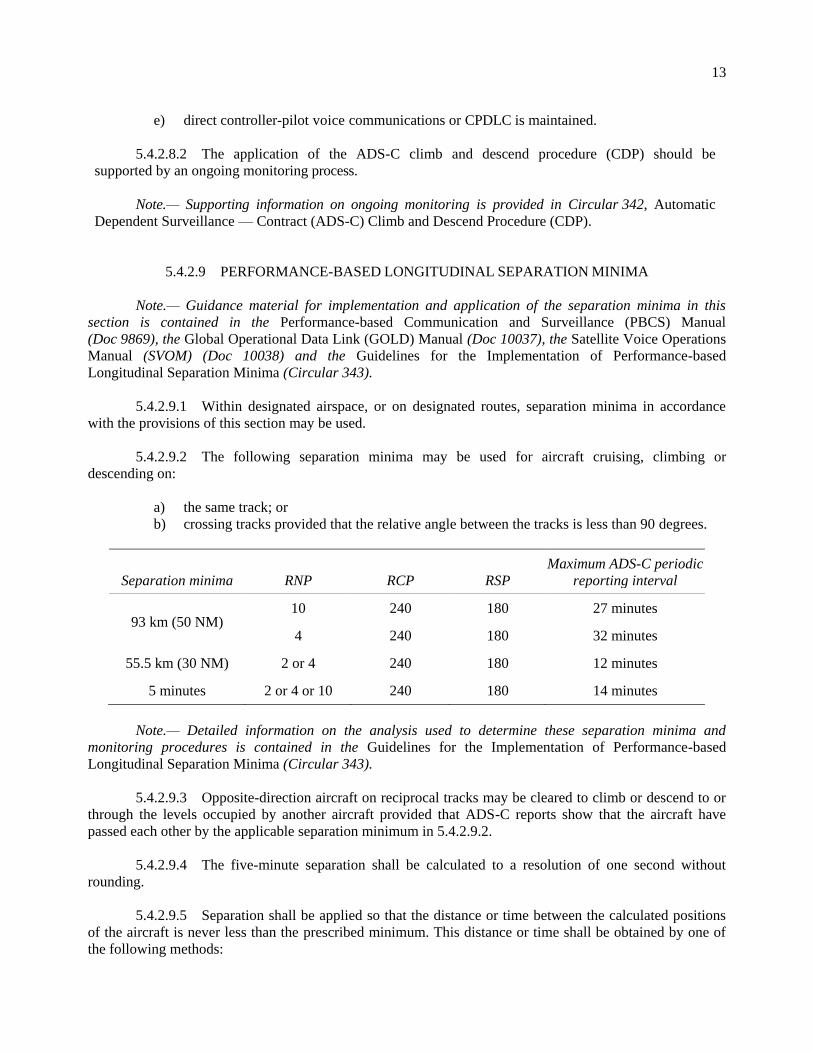
5.4.2.9 PERFORMANCE-BASED LONGITUDINAL SEPARATION MINIMA
Note.— Guidance material for implementation and application of the separation minima in this
section is contained in the Performance-based Communication and Surveillance (PBCS) Manual
(Doc 9869), the Global Operational Data Link (GOLD) Manual (Doc 10037), the Satellite Voice Operations
Manual (SVOM) (Doc 10038) and the Guidelines for the Implementation of Performance-based
Longitudinal Separation Minima (Circular 343).
5.4.2.9.1 Within designated airspace, or on designated routes, separation minima in accordance
with the provisions of this section may be used.
5.4.2.9.2 The following separation minima may be used for aircraft cruising, climbing or
descending on:
a) the same track; or
b) crossing tracks provided that the relative angle between the tracks is less than 90 degrees.
Separation minima RNP RCP RSP
Maximum ADS-C periodic
reporting interval
93 km (50 NM) 10 240 180 27 minutes
4 240 180 32 minutes
55.5 km (30 NM) 2 or 4 240 180 12 minutes
5 minutes 2 or 4 or 10 240 180 14 minutes
Note.— Detailed information on the analysis used to determine these separation minima and
monitoring procedures is contained in the Guidelines for the Implementation of Performance-based
Longitudinal Separation Minima (Circular 343).
5.4.2.9.3 Opposite-direction aircraft on reciprocal tracks may be cleared to climb or descend to or
through the levels occupied by another aircraft provided that ADS-C reports show that the aircraft have
passed each other by the applicable separation minimum in 5.4.2.9.2.
5.4.2.9.4 The five-minute separation shall be calculated to a resolution of one second without
rounding.
5.4.2.9.5 Separation shall be applied so that the distance or time between the calculated positions
of the aircraft is never less than the prescribed minimum. This distance or time shall be obtained by one of
the following methods:
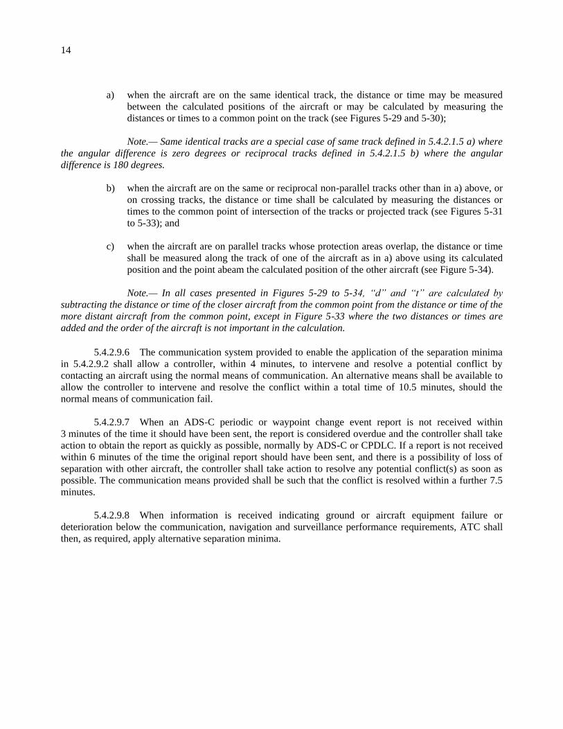
14
a) when the aircraft are on the same identical track, the distance or time may be measured
between the calculated positions of the aircraft or may be calculated by measuring the
distances or times to a common point on the track (see Figures 5-29 and 5-30);
Note.— Same identical tracks are a special case of same track defined in 5.4.2.1.5 a) where
the angular difference is zero degrees or reciprocal tracks defined in 5.4.2.1.5 b) where the angular
difference is 180 degrees.
b) when the aircraft are on the same or reciprocal non-parallel tracks other than in a) above, or
on crossing tracks, the distance or time shall be calculated by measuring the distances or
times to the common point of intersection of the tracks or projected track (see Figures 5-31
to 5-33); and
c) when the aircraft are on parallel tracks whose protection areas overlap, the distance or time
shall be measured along the track of one of the aircraft as in a) above using its calculated
position and the point abeam the calculated position of the other aircraft (see Figure 5-34).
Note.— In all cases presented in Figures 5-29 to 5-34, “d” and “t” are calculated by
subtracting the distance or time of the closer aircraft from the common point from the distance or time of the
more distant aircraft from the common point, except in Figure 5-33 where the two distances or times are
added and the order of the aircraft is not important in the calculation.
5.4.2.9.6 The communication system provided to enable the application of the separation minima
in 5.4.2.9.2 shall allow a controller, within 4 minutes, to intervene and resolve a potential conflict by
contacting an aircraft using the normal means of communication. An alternative means shall be available to
allow the controller to intervene and resolve the conflict within a total time of 10.5 minutes, should the
normal means of communication fail.
5.4.2.9.7 When an ADS-C periodic or waypoint change event report is not received within
3 minutes of the time it should have been sent, the report is considered overdue and the controller shall take
action to obtain the report as quickly as possible, normally by ADS-C or CPDLC. If a report is not received
within 6 minutes of the time the original report should have been sent, and there is a possibility of loss of
separation with other aircraft, the controller shall take action to resolve any potential conflict(s) as soon as
possible. The communication means provided shall be such that the conflict is resolved within a further 7.5
minutes.
5.4.2.9.8 When information is received indicating ground or aircraft equipment failure or
deterioration below the communication, navigation and surveillance performance requirements, ATC shall
then, as required, apply alternative separation minima.

15
Figure 5-29. Calculation of longitudinal distance/time between aircraft —
identical track, same direction (see 5.4.2.9.5 a))
Figure 5-30. Calculation of longitudinal distance/time between aircraft —
identical track, opposite direction (see 5.4.2.9.5 a))
d1 or t1
d2 or t2
d or t
Common point
d = d2 – d1
or
t = t2 – t1
Common point
d1 or t1
d2 or t2
d or t
d = d2 – d1
or
t = t2 – t1

16
Figure 5-31. Calculation of longitudinal distance/time between aircraft —
same track, but not identical and crossing tracks (see 5.4.2.9.5 b))
Figure 5-32. Calculation of longitudinal distance/time between aircraft —
same track projected, but not identical (see 5.4.2.9.5 b))
Common point
d1 or t1
d2 or t2
d = d2 – d1
or
t = t2 – t1
Common point
d1 or t1
d2 or t2
d = d2 – d1
or
t = t2 – t1

17
Figure 5-33. Calculation of longitudinal distance/time between aircraft —
opposite sides of the common point (see 5.4.2.9.5 b))
Figure 5-34. Calculation of longitudinal distance/time between aircraft –
parallel tracks (see 5.4.2.9.5 c))
End of new text.
. . .
Common point
Abeam point
d1 or t1
d2 or t2
d or t
d = d2 – d1
or
t = t2 – t1

18
5.7 SEPARATION OF DEPARTING AIRCRAFT
FROM ARRIVING AIRCRAFT
. . .
Insert new text as follows:
5.7.1.3 If an arriving aircraft is following an RNAV or RNP instrument flight procedure, a departing
aircraft may take off on a departure path that is clear of the arrival protection area for the arriving aircraft
(see Figure 5-41) provided:
j) vertical separation is applied until the arriving aircraft has reported passing the
compulsory reporting waypoint on the instrument flight procedure, the location of such
waypoint to be determined by the appropriate ATS authority;
k) the take-off takes place before the arriving aircraft crosses a designated waypoint on the
instrument flight procedure, the location of such waypoint to be determined by the
appropriate ATS authority; and
l) the departing aircraft remains clear of the arrival protection area until another form of
separation is established.
Note. — The arrival protection area is defined as the shaded area extending from a line
45 degrees from an established compulsory reporting waypoint to a line 45 degrees from the outermost edge
of the remainder of the arrival and/or approach procedure. (See Figure 5-41).
End of new text.
Editorial Note.— Renumber subsequent figures and amend related references in Chapter 5.

19
. . .
Chapter 6
. . .
6.3.2 Standard clearances for departing aircraft
. . .
6.3.2.3 CONTENTS
Standard clearances for departing aircraft shall contain the following items:
a) aircraft identification;
b) clearance limit, normally destination aerodrome;
c) designator of the assigned SID, if applicable;
d) initial cleared level except when this element is included in the SID description;
e) allocated SSR code;
f) any other necessary instructions or information not contained in the SID description, e.g.
instructions relating to change of frequency.
Note 1. — See 6.3.2.4.1 for clearances to aircraft on SID.
Note 2.— The use of a SID designator without a cleared level does not authorize the aircraft to climb
on the SID vertical profile.
6.3.2.4 CLIMB CLEARANCES ABOVE LEVELS SPECIFIED IN ON A SID
Note.— See also 11.4.2.6.2.5.
6.3.2.4.1 When a departing aircraft on a SID is cleared to climb to a level higher than the initially
cleared level or the level(s) specified in a SID, the aircraft shall follow the published vertical profile of a
SID, unless such restrictions are explicitly cancelled by ATC. Clearances to aircraft on a SID with remaining
published level and/or speed restrictions shall indicate if such restrictions are to be followed or are cancelled.
The following phraseologies shall be used with the following meanings:
a) CLIMB VIA SID TO (level):
i) climb to the cleared level and comply with published level restrictions;
ii) follow the lateral profile of the SID; and
iii) comply with published speed restrictions or ATC-issued speed control instructions as
applicable.
b) CLIMB VIA SID TO (level), CANCEL LEVEL RESTRICTION(S):

20
i) climb to the cleared level, published level restrictions are cancelled;
ii) follow the lateral profile of the SID; and
iii) comply with published speed restrictions or ATC-issued speed control instructions as
applicable.
c) CLIMB VIA SID TO (level), CANCEL LEVEL RESTRICTION(S) AT (point(s)):
i) climb to the cleared level, published level restriction(s) at the specified point(s) are
cancelled;
ii) follow the lateral profile of the SID; and
iii) comply with published speed restrictions or ATC-issued speed control instructions as
applicable.
d) CLIMB VIA SID TO (level), CANCEL SPEED RESTRICTION(S):
i) climb to the cleared level and comply with published level restrictions;
ii) follow the lateral profile of the SID; and
iii) published speed restrictions and ATC-issued speed control instructions are cancelled.
e) CLIMB VIA SID TO (level), CANCEL SPEED RESTRICTION(S) AT (point(s)):
i) climb to the cleared level and comply with published level restrictions;
ii) follow the lateral profile of the SID; and
iii) published speed restrictions are cancelled at the specified point(s).
f) CLIMB UNRESTRICTED TO (level) or CLIMB TO (level), CANCEL LEVEL AND
SPEED RESTRICTION(S):
i) climb to the cleared level, published level restrictions are cancelled;
ii) follow the lateral profile of the SID; and
iii) published speed restrictions and ATC-issued speed control instructions are cancelled.
6.3.2.4.2 If there are no remaining published level or speed restrictions on the SID, the phrase CLIMB
TO (level) should be used.
6.3.2.4.3 When subsequent speed restriction instructions are issued, and if the cleared level is
unchanged, the phrase CLIMB VIA SID TO (level) should be omitted.
6.3.2.4.4 When a departing aircraft is cleared to proceed direct to a published waypoint on the SID, the
speed and level restrictions associated with the bypassed waypoints are cancelled. All remaining published
speed and level restrictions shall remain applicable.
6.3.2.4.5 When a departing aircraft is vectored or cleared to proceed to a point that is not on the SID, all
the published speed and level restrictions of the SID are cancelled and the controller shall:
a) reiterate the cleared level;

21
b) provide speed and level restrictions as necessary; and
c) notify the pilot if it is expected that the aircraft will be instructed to subsequently rejoin the
SID.
Note.— See also 8.6.5.2 regarding prescribed obstacle clearance.
6.3.2.4.6 ATC instructions to an aircraft to rejoin a SID shall include:
a) the designator of the SID to be rejoined unless advance notification of rejoin has been
provided in accordance with 6.3.2.4.5;
b) the cleared level in accordance with 6.3.2.4.1; and
c) the position at which it is expected to rejoin the SID.
Note.— See 12.3.3.1 for phraseology on rejoin instructions.
. . .
6.3.2.5 COMMUNICATION FAILURE
6.3.2.5.1 Clearances for departing aircraft may specify an initial or intermediate a cleared level other
than that indicated in the filed flight plan for the en-route phase of flight, without a time or geographical
limit for the initialcleared level. Such clearances will normally be used to facilitate the application of tactical
control methods by ATC, normally through the use of an ATS surveillance system.
6.3.2.5.2 Where clearances for departing aircraft containing no time or geographical limit for an initial
or intermediate level a cleared levelare utilized, action to be taken by an aircraft experiencing air-ground
communication failure in the event the aircraft has been radar vectored away from the route specified in its
current flight plan should be prescribed on the basis of a regional air navigation agreement and included in
the SID description or published in AIPs.
. . .
6.5.2 Standard clearances for arriving aircraft
. . .
6.5.2.3 CONTENTS
Standard clearances for arriving aircraft shall contain the following items:
a) aircraft identification;
b) designator of the assigned STAR if applicable;
c) runway-in-use, except when part of the STAR description;
d) initial cleared level, except when this element is included in the STAR description; and
e) any other necessary instructions or information not contained in the STAR description, e.g. change
of communications.

22
Note 1.— See 6.5.2.4.1 for clearances on a STAR.
Note 2.— The use of a STAR designator without a cleared level does not authorize the aircraft to
descend on the STAR vertical profile.
6.5.2.4 DESCENT BELOW LEVELS SPECIFIED IN A STAR CLEARANCES ON A STAR
Note.— See also 11.4.2.6.2.5.
When an arriving aircraft on a STAR is cleared to descend to a level lower than the level or the level(s)
specified in a STAR, the aircraft shall follow the published vertical profile of a STAR, unless such
restrictions are explicitly cancelled by ATC. Published minimum levels based on terrain clearance shall
always be applied.
6.5.2.4.1 Clearances to aircraft on a STAR with remaining published level and/or speed restrictions
shall indicate if such restrictions are to be followed or are cancelled. The following phraseologies shall be
used with the following meaning:
a) DESCEND VIA STAR TO (level):
i) descend to the cleared level and comply with published level restrictions;
ii) follow the lateral profile of the STAR; and
iii) comply with published speed restrictions or ATC-issued speed control instructions as
applicable.
b) DESCEND VIA STAR TO (level), CANCEL LEVEL RESTRICTION(S):
i) descend to the cleared level, published level restrictions are cancelled;
ii) follow the lateral profile of the STAR; and
iii) comply with published speed restrictions or ATC-issued speed control instructions as
applicable.
c) DESCEND VIA STAR TO (level), CANCEL LEVEL RESTRICTION(S) AT (point(s)):
i) descend to the cleared level, published level restriction(s) at the specified point(s) are
cancelled;
ii) follow the lateral profile of the STAR; and
iii) comply with published speed restrictions or ATC-issued speed control instructions as
applicable.
d) DESCEND VIA STAR TO (level), CANCEL SPEED RESTRICTION(S):
i) descend to the cleared level and comply with published level restrictions;
ii) follow the lateral profile of the STAR; and
iii) published speed restrictions and ATC-issued speed control instructions are cancelled.
e) DESCEND VIA STAR TO (level), CANCEL SPEED RESTRICTION(S) AT (point(s)):

23
i) descend to the cleared level and comply with published level restrictions;
ii) follow the lateral profile of the STAR; and
iii) published speed restrictions are cancelled at the specified point(s).
f) DESCEND UNRESTRICTED TO (level) or DESCEND TO (level), CANCEL LEVEL
AND SPEED RESTRICTION(S):
i) descend to the cleared level, published level restrictions are cancelled;
ii) follow the lateral profile of the STAR; and
iii) published speed restrictions and ATC-issued speed control instructions are cancelled.
6.5.2.4.2 If there are no remaining published level or speed restrictions on the STAR, the phrase
DESCEND TO (level) should be used.
6.5.2.4.3 When subsequent speed restriction instructions are issued and if the cleared level is
unchanged, the phrase DESCEND VIA STAR TO (level) should be omitted.
6.5.2.4.4 When an arriving aircraft is cleared to proceed direct to a published waypoint on the STAR,
the speed and level restrictions associated with the bypassed waypoints are cancelled. All remaining
published speed and level restrictions shall remain applicable.
6.5.2.4.5 When an arriving aircraft is vectored or cleared to proceed to a point that is not on the STAR,
all the published speed and level restrictions of the STAR are cancelled and the controller shall:
a) reiterate the cleared level;
b) provide speed and level restrictions as necessary and;
c) notify the pilot if it is expected that the aircraft will be instructed to subsequently rejoin the
STAR.
Note.— See 8.6.5.2 regarding prescribed obstacle clearance.
6.5.2.4.6 ATC instructions to an aircraft to rejoin a STAR shall include:
a) the designator of the STAR to be rejoined, unless advance notification of rejoin has been
provided in accordance with 6.5.2.4.5;
b) the cleared level on rejoining the STAR in accordance with 6.5.2.4.1; and
c) the position at which it is expected to rejoin the STAR.
Note.— See 12.3.3.2 for phraseology on rejoin instructions.
. . .
24
Chapter 7
PROCEDURES FOR AERODROME CONTROL SERVICE
. . .
7.9 CONTROL OF DEPARTING AIRCRAFT
. . .
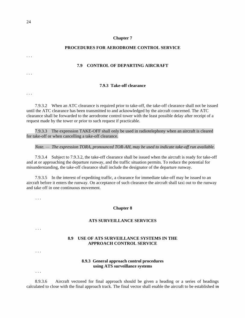
7.9.3 Take-off clearance
. . .
7.9.3.2 When an ATC clearance is required prior to take-off, the take-off clearance shall not be issued
until the ATC clearance has been transmitted to and acknowledged by the aircraft concerned. The ATC
clearance shall be forwarded to the aerodrome control tower with the least possible delay after receipt of a
request made by the tower or prior to such request if practicable.
7.9.3.3 The expression TAKE-OFF shall only be used in radiotelephony when an aircraft is cleared
for take-off or when cancelling a take-off clearance.
Note. — The expression TORA, pronounced TOR-AH, may be used to indicate take-off run available.
7.9.3.4 Subject to 7.9.3.2, the take-off clearance shall be issued when the aircraft is ready for take-off
and at or approaching the departure runway, and the traffic situation permits. To reduce the potential for
misunderstanding, the take-off clearance shall include the designator of the departure runway.
7.9.3.5 In the interest of expediting traffic, a clearance for immediate take-off may be issued to an
aircraft before it enters the runway. On acceptance of such clearance the aircraft shall taxi out to the runway
and take off in one continuous movement.
. . .
Chapter 8
ATS SURVEILLANCE SERVICES
. . .
8.9 USE OF ATS SURVEILLANCE SYSTEMS IN THE
APPROACH CONTROL SERVICE
. . .
8.9.3 General approach control procedures
using ATS surveillance systems
. . .
8.9.3.6 Aircraft vectored for final approach should be given a heading or a series of headings
calculated to close with the final approach track. The final vector shall enable the aircraft to be established in

25
level flight on the final approach track prior to intercepting the specified or nominal glide path of the
approach procedure from below if an MLS, ILS or radar approach is to be made, and should provide an
intercept angle with the final approach track of 45 degrees or less.
Note.— See Chapter 6, Section 6.7.3.2, and Section 6.7.3.2.3 concerning vectoring and level flight
requirements of independent parallel approaches, respectively.
. . .
8.9.4.2 When clearance for the approach is issued, aircraft shall maintain last assigned level until
intercepting the specified or nominal glide path of the approach procedure. If ATC requires an aircraft to
intercept the glide path at a level other than a level flight segment depicted on the instrument approach chart,
ATC shall instruct the pilot to maintain the particular level until established on the glide path.
8.9.4.32 The controller shall be responsible for maintaining separation specified in 8.7.3 between
succeeding aircraft on the same final approach, except that the responsibility may be transferred to the
aerodrome controller in accordance with procedures prescribed by the appropriate ATS authority and
provided an ATS surveillance system is available to the aerodrome controller.
8.9.4.43 Transfer of control of succeeding aircraft on final approach to the aerodrome controller shall
be effected in accordance with procedures prescribed by the appropriate ATS authority.
8.9.4.54 Transfer of communications to the aerodrome controller should be effected at such a point or
time that clearance to land or alternative instructions can be issued to the aircraft in a timely manner.
. . .
Chapter 12
PHRASEOLOGIES
. . .
12.3 ATC PHRASEOLOGIES
12.3.1 General
Circumstances
Phraseologies
12.3.1.2 LEVEL CHANGES, REPORTS AND
RATES
. . . . . .
… clearance to cancel level
restriction(s) of the vertical profile of
a SID during climb
z) CLIMB TO (level) [LEVEL RESTRICTION(S)
(SID designator) CANCELLED (or) LEVEL
RESTRICTION(S) (SID designator) AT (point)
CANCELLED];

26
Circumstances
Phraseologies
… clearance to cancel level
restriction(s) of the vertical profile of
a STAR during descent
aa) DESCEND TO (level) [LEVEL
RESTRICTION(S) (STAR designator) CANCELLED
(or) LEVEL RESTRICTION(S) (STAR designator)
AT (point) CANCELLED].
... clearance to climb on a SID which
has published level and/or speed
restrictions, where the pilot is to
climb to the cleared level and comply
with published level restrictions,
follow the lateral profile of the SID;
and comply with published speed
restrictions or ATC issued speed
control instructions as applicable.
z) CLIMB VIA SID TO (level)
... clearance to cancel level
restriction(s) of the vertical profile of
a SID during climb
aa) [CLIMB VIA SID TO (level)], CANCEL
LEVEL RESTRICTION(S)
... clearance to cancel specific level
restriction(s) of the vertical profile of
a SID during climb
bb) [CLIMB VIA SID TO (level)], CANCEL
LEVEL RESTRICTION(S) AT (point(s))
... clearance to cancel speed
restrictions of a SID during climb
cc) [CLIMB VIA SID TO (level)], CANCEL SPEED
RESTRICTION(S)
... clearance to cancel specific speed
restrictions of a SID during climb
dd) [CLIMB VIA SID TO (level)], CANCEL SPEED
RESTRICTION(S) AT (point(s))
…clearance to climb and to cancel
speed and level restrictions of a SID
ee) CLIMB UNRESTRICTED TO (level) (or)
CLIMB TO (level), CANCEL LEVEL AND
SPEED RESTRICTIONS
... clearance to descend on a STAR
which has published level and/or
speed restrictions, where the pilot is
to descend to the cleared level and
comply with published level
restrictions, follow the lateral profile
of the STAR and comply with
published speed restrictions or ATC
issued speed control instructions.
ff) DESCEND VIA STAR TO (level)
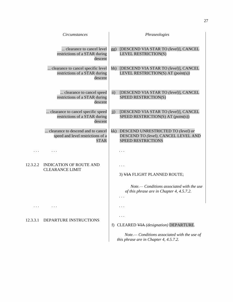
27
Circumstances
Phraseologies
... clearance to cancel level
restrictions of a STAR during
descent
gg) [DESCEND VIA STAR TO (level)], CANCEL
LEVEL RESTRICTION(S)
... clearance to cancel specific level
restrictions of a STAR during
descent
hh) [DESCEND VIA STAR TO (level)], CANCEL
LEVEL RESTRICTION(S) AT (point(s))
... clearance to cancel speed
restrictions of a STAR during
descent
ii) [DESCEND VIA STAR TO (level)], CANCEL
SPEED RESTRICTION(S)
... clearance to cancel specific speed
restrictions of a STAR during
descent
jj) [DESCEND VIA STAR TO (level)], CANCEL
SPEED RESTRICTION(S) AT (point(s))
... clearance to descend and to cancel
speed and level restrictions of a
STAR
kk) DESCEND UNRESTRICTED TO (level) or
DESCEND TO (level), CANCEL LEVEL AND
SPEED RESTRICTIONS
. . . . . . . . .
12.3.2.2
INDICATION OF ROUTE AND
CLEARANCE LIMIT
. . .
3) VIA FLIGHT PLANNED ROUTE;
Note.— Conditions associated with the use
of this phrase are in Chapter 4, 4.5.7.2.
. . .
. . . . . . . . .
12.3.3.1
DEPARTURE INSTRUCTIONS
. . .
f) CLEARED VIA (designation) DEPARTURE.
Note.— Conditions associated with the use of
this phrase are in Chapter 4, 4.5.7.2.

28
Circumstances
Phraseologies
…clearance to proceed direct with
advance notice of a future instruction
to rejoin the SID
g) CLEARED DIRECT (waypoint), CLIMB TO
(level), EXPECT TO REJOIN SID [(sid
designator)] [AT (waypoint)]
then
REJOIN SID [(sid designator)] [AT (waypoint)]
h) CLEARED DIRECT (waypoint),CLIMB TO
(level)
then
REJOIN SID (sid designator) AT (waypoint)
12.3.3.2
APPROACH INSTRUCTIONS
a) CLEARED (or PROCEED) VIA (designation)
ARRIVAL;
b) CLEARED TO (clearance limit) VIA
(designation)
c) CLEARED (or PROCEED) VIA (details of the
route to be followed)
…clearance to proceed direct with
advance notice of a future instruction
to rejoin the STAR
d) CLEARED DIRECT (waypoint), DESCEND TO
(level), EXPECT TO REJOIN STAR [(star
designator)] AT (waypoint)
then
REJOIN STAR [(star designator)] [AT
(waypoint)]
e) CLEARED DIRECT (waypoint), DESCEND TO
(level)
then
REJOIN STAR (star designator) AT (waypoint)
d)f) CLEARED (type of approach) APPROACH
[RUNWAY (number)];
Editorial Note.— Subsequent bullets to be
renumbered accordingly.
. . . . . .
29
Circumstances
Phraseologies
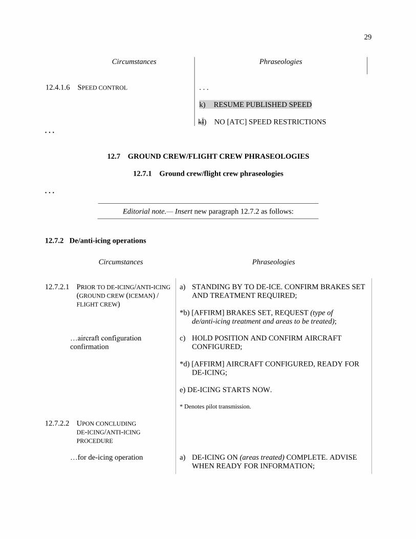
12.4.1.6
SPEED CONTROL
. . .
k) RESUME PUBLISHED SPEED
kl) NO [ATC] SPEED RESTRICTIONS
. . .
12.7 GROUND CREW/FLIGHT CREW PHRASEOLOGIES
12.7.1 Ground crew/flight crew phraseologies
. . .
Editorial note.— Insert new paragraph 12.7.2 as follows:
12.7.2 De/anti-icing operations
Circumstances Phraseologies
12.7.2.1 PRIOR TO DE-ICING/ANTI-ICING
(GROUND CREW (ICEMAN) /
FLIGHT CREW)
a) STANDING BY TO DE-ICE. CONFIRM BRAKES SET
AND TREATMENT REQUIRED;
*b) [AFFIRM] BRAKES SET, REQUEST (type of
de/anti-icing treatment and areas to be treated);
…aircraft configuration
confirmation
c) HOLD POSITION AND CONFIRM AIRCRAFT
CONFIGURED;
*d) [AFFIRM] AIRCRAFT CONFIGURED, READY FOR
DE-ICING;
e) DE-ICING STARTS NOW.
* Denotes pilot transmission.
12.7.2.2 UPON CONCLUDING
DE-ICING/ANTI-ICING
PROCEDURE
…for de-icing operation a) DE-ICING ON (areas treated) COMPLETE. ADVISE
WHEN READY FOR INFORMATION;

30
Circumstances Phraseologies
…for a two-step de-icing/anti-
icing operation
b) TYPE OF FLUID (Type I or II or III or IV);
c) HOLDOVER TIME STARTED AT (time);
d) ANTI-ICING CODE (appropriate anti-icing code)
Note.— Anti-icing code example:
A de-icing/anti-icing procedure whose last step is the use of a
mixture of 75% of a Type II fluid and 25% water, commencing
at 13:35 local time, is recorded as follows:
TYPE II/75 13:35 (followed by complete name of anti-
icing fluid)
e) FINAL STEP STARTED AT (time);
… De-icing/anti-icing complete f) POST DE-ICING CHECK COMPLETED;
g) PERSONNEL AND EQUIPMENT CLEAR OF
AIRCRAFT;
12.7.2.3 ABNORMAL OPERATIONS
… for spray nozzle proximity
sensor activation
… for other aircraft having an
emergency on the de-icing bay
a) BE ADVISED NOZZLE PROXIMITY ACTIVATION
ON (significant point on aircraft) [NO VISUAL
DAMAGE or DAMAGE (description of damage)
OBSERVED] [SAY INTENTIONS];
b) EMERGENCY IN DE-ICING BAY (de-icing bay
number) [SHUT DOWN ENGINES or STANDBY FOR
FURTHER INSTRUCTIONS].
End of new text
. . .

31
Chapter 13
AUTOMATIC DEPENDENT SURVEILLANCE —
CONTRACT (ADS-C) SERVICES
13.1 GENERAL
Note.— Guidance material concerning the implementation of ADS-C is contained in the Global
Operational Data Link (GOLD) Manual (Doc 10037).
. . .
13.2 ADS-C GROUND SYSTEM CAPABILITIES
13.2.1 ADS-C ground systems used in the provision of air traffic services shall have a very high
level of reliability, availability and integrity. The possibility of system failures or significant system
degradations that may cause complete or partial interruptions of service shall be very remote. Backup
facilities shall be provided.
Note 1.— An ADS-C ground system will normally consist of a number of integrated elements,
including communication interfaces, a data-processing system and one or more controller interfaces.
Note 2.— Information pertaining to use of ADS-C and to system reliability, availability and
integrity is contained in the Manual of Air Traffic Services Data Link Applications (Doc 9694)
Performance-based Communication and Surveillance (PBCS) Manual (Doc 9869).
. . .
13.4 USE OF ADS-C IN THE PROVISION OF
AIR TRAFFIC CONTROL SERVICE
. . .
13.4.3 Provision of ADS-C services
13.4.3.1 GENERAL
The number of aircraft simultaneously provided with ADS-C services shall not exceed that which can safely
be handled under the prevailing circumstances, taking into account:
a) the complexity of the traffic situation and associated workload within the sector or area of
responsibility of the controller; b) the level of automation of the ADS-C ground system; c) the overall technical performance of the ADS-C systems and communications systems, including
possible degradations that would require use of backup facilities;

32
d) the overall performance of the backup surveillance and communications systems; and e) the effect of loss of controller-pilot communications.
Note.— Further guidance on the factors to be considered can be found in the Manual of Air Traffic
Services Data Link Applications (Doc 9694).
. . .
13.4.3.4 GENERAL ADS-C PROCEDURES
. . .
13.4.3.4.3 ADS-C AGREEMENTS
. . .
13.4.3.4.3.2 In airspace where procedural separation is being applied, ADS-C agreements shall, as
a minimum, contain the following ADS contracts: a) a periodic contract at an interval appropriate to the airspace requirements; b) an event contract, specifying the following: b1) a waypoint change event contract; c2) a lateral deviation event contract; and d3) a level range deviation event contract.
Note 1.— Circumstances may dictate that periodic contract reporting rate might be increased on
receipt of a lateral deviation or level range deviation event report.
Note 2.— A vertical rate change event specified at, for example, a negative vertical rate
(i.e. a descent) exceeding 27 m/s (5 000 ft/min), may provide additional indication of an abnormal situation.
13.4.3.4.3.3 Upon receipt of an event report indicating a deviation from the clearance, the ATC
unit shall establish a periodic contract at a reduced reporting interval, as deemed appropriate, requesting the
ground vector data block in addition to basic ADS-C data block. The ATC unit shall advise the flight crew
of the observed deviation and ascertain its intention using CPDLC or voice, as appropriate.
13.4.3.4.3.4 The reduced ADS-C periodic reporting interval shall be retained until the aircraft has
resumed its clearance, at which time the event contract shall be re-established and the normal periodic
contract restored. Action should be taken by the ATC unit to notify proximate aircraft if appropriate.
13.4.3.4.3.35 When the application of specified separation minima is dependent on the reporting
interval of periodic position reports, the ATC unit shall not establish periodic contracts with a reporting
interval greater than the required reporting interval. 13.4.3.4.3.46 Where an expected position report is not received within a prescribed time
parameter, action shall be taken, as appropriate, to ascertain the position of the aircraft. Note 1.— This may be achieved by the use of an ADS demand contract, CPDLC or voice

33
communications, or receipt of a subsequent periodic report. Note 2.— Requirements concerning the provision of an alerting service are contained in Chapter 9.
13.4.3.4.3.5 An ADS-C aircraft observed to deviate significantly from its cleared flight profile shall
be advised accordingly. Action shall be taken, as appropriate, to ascertain the position and intentions of the
aircraft. Appropriate action shall also be taken if, in the opinion of the controller, such deviation is likely to
affect the air traffic service being provided.
Note.— This may be achieved by the use of an ADS demand contract, CPDLC or voice communications.
. . .
13.4.3.4.5 EMERGENCY AND/OR URGENCY REPORTS
Note.— To indicate that it is in a state of emergency or to transmit other urgent information the
state of emergency is terminated, an aircraft equipped with ADS-C might operate the emergency and/or
urgency mode as follows:
a) emergency; and
b) communication failure;
c) unlawful interference;
d) minimum fuel; and/or
e) medical.
b) emergency cancelled.
13.4.3.4.5.1 When an ADS-C emergency and/or urgency report is received with an emergency
status indication, the controller with responsibility for the flight must acknowledge receipt of the information
by the most appropriate means of communication. 13.4.3.4.5.2 Both the aircraft and the ADS-C ground system shall be capable of supporting an
emergency and/or urgency mode of ADS-C operation to assist ATC alerting procedures and to assist search
and rescue operations. In the event of an aircraft in, or appearing to be in, any form of emergency, all possible
assistance shall be provided by the controller. Note.— The ADS-C airborne system will provide for a pilot-initiated emergency and/or urgency
mode. It may also permit the aircraft to automatically establish the emergency and/or urgency mode. 13.4.3.4.5.3 The ADS-C ground system shall recognize the initiation, modification and termination
of an emergency and/or urgency mode and alert the controller. The ADS-C ground system shall be able to
modify the emergency and/or urgency reporting rate if necessary. The ADS-C ground system shall be able to
suppress an emergency/urgency indication. . . .
13.5.3 Application of horizontal separation using ADS-C position information
. . .
13.5.3.1 ADS-C-based longitudinal distance separation minima are detailed at 5.4.2.9 6.4 of
Chapter 5.
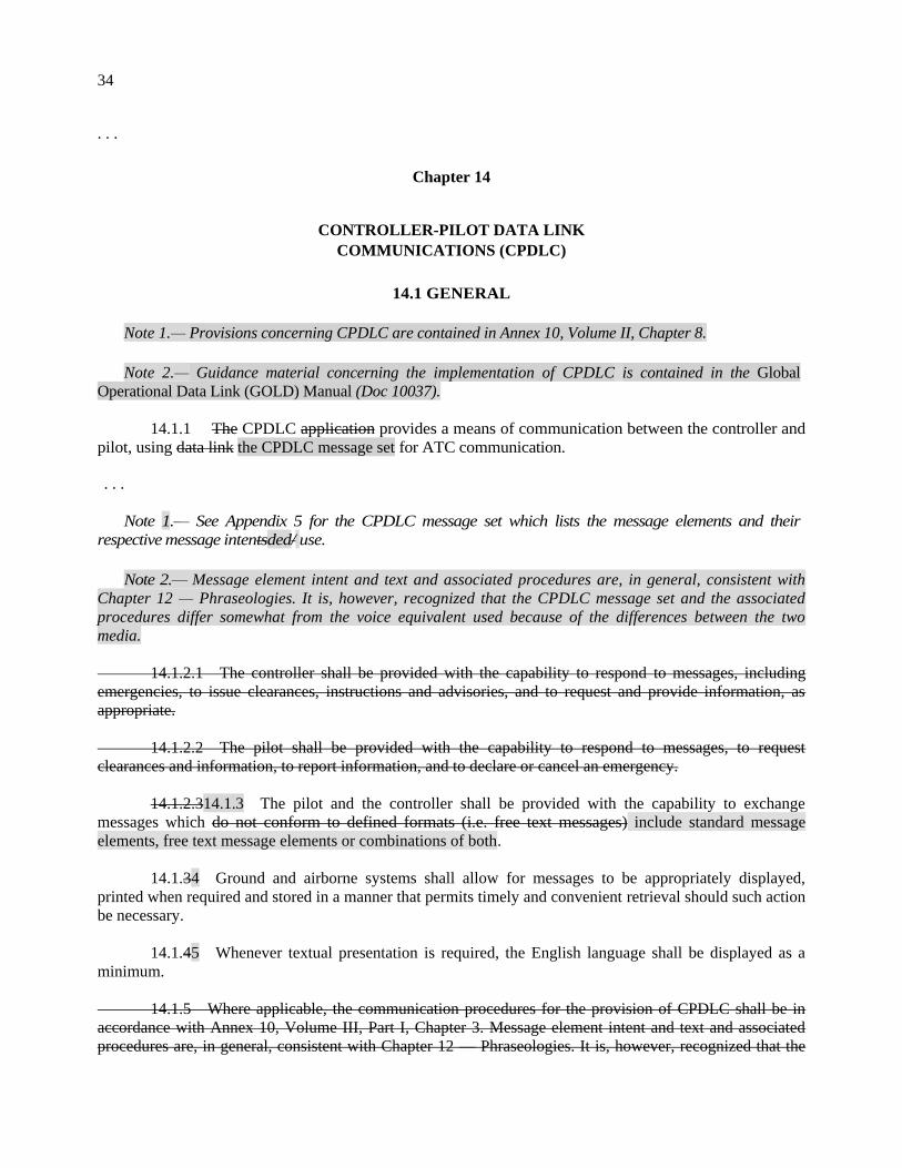
34
. . .
Chapter 14
CONTROLLER-PILOT DATA LINK
COMMUNICATIONS (CPDLC)
14.1 GENERAL
Note 1.— Provisions concerning CPDLC are contained in Annex 10, Volume II, Chapter 8.
Note 2.— Guidance material concerning the implementation of CPDLC is contained in the Global
Operational Data Link (GOLD) Manual (Doc 10037).
14.1.1 The CPDLC application provides a means of communication between the controller and
pilot, using data link the CPDLC message set for ATC communication. . . .
Note 1.— See Appendix 5 for the CPDLC message set which lists the message elements and their
respective message intentsded/ use.
Note 2.— Message element intent and text and associated procedures are, in general, consistent with
Chapter 12 — Phraseologies. It is, however, recognized that the CPDLC message set and the associated
procedures differ somewhat from the voice equivalent used because of the differences between the two
media.
14.1.2.1 The controller shall be provided with the capability to respond to messages, including
emergencies, to issue clearances, instructions and advisories, and to request and provide information, as
appropriate.
14.1.2.2 The pilot shall be provided with the capability to respond to messages, to request
clearances and information, to report information, and to declare or cancel an emergency.
14.1.2.314.1.3 The pilot and the controller shall be provided with the capability to exchange
messages which do not conform to defined formats (i.e. free text messages) include standard message
elements, free text message elements or combinations of both.
14.1.34 Ground and airborne systems shall allow for messages to be appropriately displayed,
printed when required and stored in a manner that permits timely and convenient retrieval should such action
be necessary.
14.1.45 Whenever textual presentation is required, the English language shall be displayed as a
minimum.
14.1.5 Where applicable, the communication procedures for the provision of CPDLC shall be in
accordance with Annex 10, Volume III, Part I, Chapter 3. Message element intent and text and associated
procedures are, in general, consistent with Chapter 12 — Phraseologies. It is, however, recognized that the

35
CPDLC message set and the associated procedures differ somewhat from the voice equivalent used because
of the differences between the two media; one being direct-speech and the other an exchange of data, the
latter of which can be displayed and/or printed.
. . .
14.3 EXCHANGE OF OPERATIONAL CPDLC MESSAGES
14.3.1 The controller or pilot shall construct CPDLC messages using the defined message set, a
free text message standard message elements, free text message elements or a combination of both.
. . .
14.3.1.2 When CPDLC is being used, and the intent of the message is included in the CPDLC
message set contained in Appendix 5, the associated message standard message elements shall be used.
. . .
14.3.2 Message attributes dictate certain message handling requirements for the CPDLC user receiving a
message. Each CPDLC message has three two attributes: Urgency, Alert and Response.
14.3.2.1 URGENCY
The urgency attribute delineates the queuing requirements for received messages that are displayed to the
end-user. Urgency types are presented in Table 14-1.
14.3.2.21 ALERT
The alert attribute delineates the type of alerting required upon message receipt. Alert types are presented in
Table 14-21.
14.3.2.32 RESPONSE
14.3.2.32.1 The response attribute delineates valid responses for a given message element.
Response types are presented in Table 14-32 for uplink messages and Table 14-43 for downlink messages.
14.3.2.32.2 When a multi-element message requires a response, and the response is in the form
of a single message element, the response shall apply to all message elements.
. . .
Table 14-1. Urgency attribute (uplink and downlink)
Type Description Precedence
D Distress 1

36
U Urgent 2
N Normal 3
L Low 4
Table 14-21. Alert attribute (uplink and downlink)
. . .
Table 14-32. Response attribute (uplink)
. . .
Table 14-43. Response attribute (downlink)
Type Response required Valid responses Precedence
Y Yes Any CPDLC uplink message,
LOGICAL ACKNOWLEDGEMENT (only if
required)
1
N No, unless logical
acknowledgement
required
LOGICAL ACKNOWLEDGEMENT (only if
required),
SERVICE UNAVAILABLE MESSAGE NOT
SUPPORTED BY THIS ATC UNIT,
FLIGHT PLAN NOT HELD,
ERROR
2
. . .
14.3.3 Transfer of CPDLC
Note.— Details on CPDLC transfer can be found in the Manual of Air Traffic Services Data Link
Applications (Doc 9694)
. . .
14.3.4 Free text messages elements
Note — Provisions concerning the use of free text message elements are contained in Annex 10,
Volume II, Chapter 8.
14.3.4.1 The use of free text message elements by controllers or pilots, other than standardized
free text message elements, should be avoided. Standardized free text message elements should be
preformatted and made available to controllers and pilots to facilitate their use.
Note 1.— While it is recognized that non-routine and emergency situations may necessitate use of
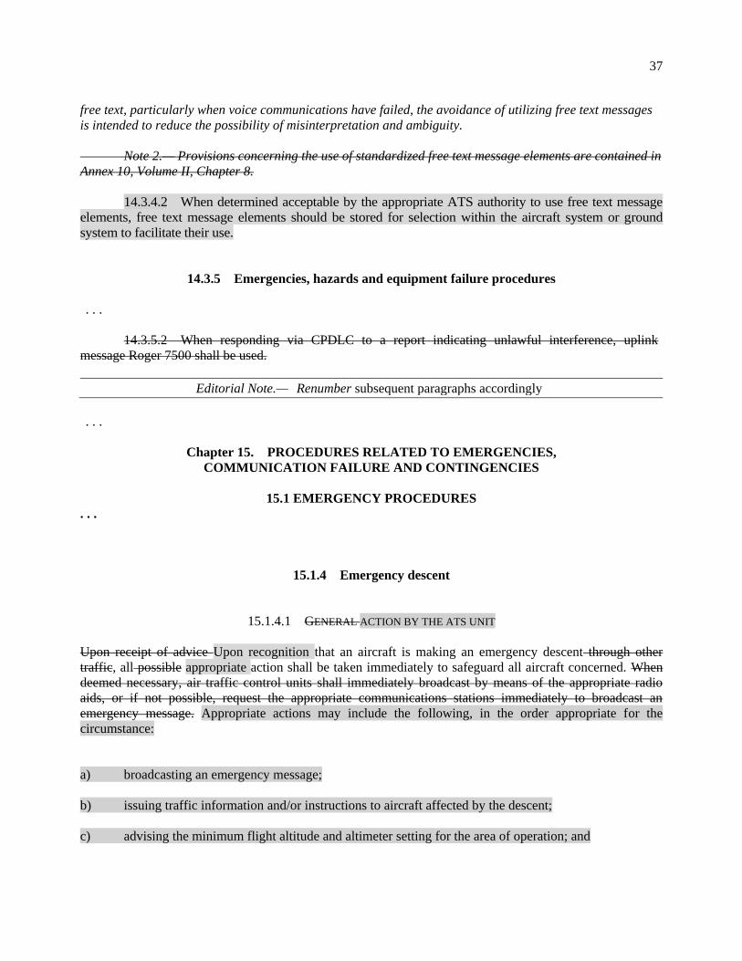
37
free text, particularly when voice communications have failed, the avoidance of utilizing free text messages
is intended to reduce the possibility of misinterpretation and ambiguity.
Note 2.— Provisions concerning the use of standardized free text message elements are contained in
Annex 10, Volume II, Chapter 8.
14.3.4.2 When determined acceptable by the appropriate ATS authority to use free text message
elements, free text message elements should be stored for selection within the aircraft system or ground
system to facilitate their use.
14.3.5 Emergencies, hazards and equipment failure procedures
. . .
14.3.5.2 When responding via CPDLC to a report indicating unlawful interference, uplink
message Roger 7500 shall be used.
Editorial Note.— Renumber subsequent paragraphs accordingly
. . .
Chapter 15. PROCEDURES RELATED TO EMERGENCIES,
COMMUNICATION FAILURE AND CONTINGENCIES
15.1 EMERGENCY PROCEDURES
. . .
15.1.4 Emergency descent
15.1.4.1 GENERAL ACTION BY THE ATS UNIT
Upon receipt of advice Upon recognition that an aircraft is making an emergency descent through other
traffic, all possible appropriate action shall be taken immediately to safeguard all aircraft concerned. When
deemed necessary, air traffic control units shall immediately broadcast by means of the appropriate radio
aids, or if not possible, request the appropriate communications stations immediately to broadcast an
emergency message. Appropriate actions may include the following, in the order appropriate for the
circumstance:
a) broadcasting an emergency message;
b) issuing traffic information and/or instructions to aircraft affected by the descent;
c) advising the minimum flight altitude and altimeter setting for the area of operation; and

38
d) informing any other ATS units which may be affected by the emergency descent.
15.1.4.2 ACTION BY THE PILOT-IN-COMMAND OF THE AIRCRAFT IN AN EMERGENCY DESCENT
It is expected that aircraft receiving such a broadcast will clear the specified areas and stand by on the
appropriate radio frequency for further clearances from the air traffic control unit.
The pilot shall take the following steps as soon as practicable in the order appropriate for the circumstance:
a) navigate as deemed appropriate by the pilot;
b) advise the appropriate ATS unit of the emergency descent and if able intentions;
c) set transponder to Code 7700 and, if applicable, select the appropriate emergency mode on ADS-B
and/or ADS-C;
d) turn on aircraft exterior lights (commensurate with appropriate operating limitations);
e) watch for conflicting traffic both visually and by reference to ACAS (if equipped); and
f) when emergency descent is complete, coordinate further intentions with the appropriate ATS unit.
Note.— Procedures for the use of ACAS are contained in PANS-OPS, Volume I, Part III, Section 3,
Chapter 3.
15.1.4.3 SUBSEQUENT ACTION BY THE AIR TRAFFIC CONTROL UNIT
Immediately after such an emergency broadcast has been made the ACC, the approach control unit, or the
aerodrome control tower concerned shall forward further clearances to all aircraft involved as to additional
procedures to be followed during and subsequent to the emergency descent. The ATS unit concerned shall
additionally inform any other ATS units and control sectors which may be affected.
15.1.4.3 ACTION BY THE PILOT OF AIRCRAFT
RECEIVING EMERGENCY DESCENT BROADCAST
Unless specifically instructed by the ATS unit to clear the area or threatened by immediate danger, the pilot
shall take the following actions:
a) continue according to current clearance and maintain listening watch on the frequency in use for any
further instructions from the ATS unit; and
b) watch for conflicting traffic both visually and by reference to ACAS (if equipped).
. . .

39
15.3 AIR-GROUND COMMUNICATIONS FAILURE
Note 4.— See also Chapter 6, 6.3.2.5, concerning departure clearances containing no geographical
or time limit for an initial cleared level below the flight planned level and procedures to be applied in
relation to an aircraft experiencing air-ground communication failure under such circumstances.
. . .
15.7 OTHER ATC CONTINGENCY PROCEDURES
. . .
Insert new text as follows:
15.7.5 Autonomous runway incursion warning system (ARIWS)
Note 1.— The generation of ARIWS warnings is a function based on surveillance data. The objective
of the ARIWS function is to assist flight crews and vehicle drivers in the prevention of runway incursions by
generating, in a timely manner, a direct warning of a possible runway hazard making it unsafe to enter, to
cross a runway or to take-off
Note 2.— The function of ARIWS is to operate independently from ATC, and the warnings are
generated for pilots and vehicle drivers.
Note 3.— Annex 14, Attachment A, Section 21, provides description of an autonomous runway
incursion warning system (ARIWS) and information on its use.
15.7.5.1 In the event an ARIWS warning is generated that conflicts with the ATC clearance, the
following action shall be taken by flight crew and vehicle drivers:
a) The flight crew or vehicle driver shall give priority to the ARIWS warning over the ATC
clearance. They shall not proceed onto the runway or commence the take-off roll. The flight
crew or vehicle driver shall inform the controller of the ARIWS warning and await further
clearance.
b) In the event the aircraft or vehicle has initiated actions to comply with a clearance that conflicts
with the warning, the flight crew or the vehicle driver shall use the warning to exercise their
best judgement and full authority in the choice of the best course of action to resolve any
potential conflict. The controller should be informed, when practicable, of the ARIWS warning.
15.7.5.2 ATS units shall have procedures in place for situations when controllers are informed of
ARIWS warnings, including how to disable the ARIWS in case of malfunctions.
End of new text.
Renumber subsequent paragraphs accordingly

40
Chapter 16
MISCELLANEOUS PROCEDURES
. . .
16.5 STRATEGIC LATERAL OFFSET PROCEDURES (SLOP)
. . .
16.5.2 Strategic lateral offsets shall be authorized only in en-route airspace as follows:
a) where the lateral separation minima or spacing between route centre lines is 55.542.6 km
(3023 NM) or more, offsets to the right of the centre line relative to the direction of flight in
tenths of a nautical mile up to a maximum of 3.7 km (2 NM); and
b) where the lateral separation minima or spacing between route centre lines is 11.1 km (6 NM) or
more and less than 55.542.6 km (3023 NM), offsets to the right of the centre line relative to the
direction of flight in tenths of a nautical mile up to a maximum of 0.9 km (0.5 NM).
. . .
Appendix 2
FLIGHT PLAN
. . .
2. Instructions for the completion of the flight plan form
. . .
2.2 Instructions for insertion of ATS data
. . .
ITEM 10: EQUIPMENT AND CAPABILITIES
. . .
Radiocommunication, navigation and
approach aid equipment and capabilities
. . .
INSERT one or more of the following letters to indicate the serviceable COM/NAV/approach aid equipment and capabilities available:

41
A GBAS landing system
B LPV (APV with SBAS)
C LORAN C
D DME
E1 FMC WPR ACARS
E2 D-FIS ACARS
E3 PDC ACARS
F ADF
G GNSS If any portion of
the flight is planned to be
conducted under IFR, it
refers to GNSS receivers
that comply with the
requirements of
Annex 10, Volume I (See
Note 2)
H HF RTF
I Inertial Navigation
J1 CPDLC ATN VDL
Mode 2 (See Note 3)
J2 CPDLC FANS 1/A
HFDL
J3 CPDLC FANS 1/A
VDL Mode A
J4 CPDLC FANS 1/A
VDL Mode 2
J5 CPDLC FANS 1/A
SATCOM
(INMARSAT)
J6 CPDLC FANS 1/A
SATCOM (MTSAT)
J7 CPDLC FANS 1/A SATCOM
(Iridium)
K MLS
L ILS
M1 ATC SATVOICE RTF SATCOM
(INMARSAT)
M2 ATC SATVOICE RTF (MTSAT)
M3 ATC SATVOICE RTF (Iridium)
O VOR
P1–P9 Reserved for RCP CPDLC RCP
400 (See Note 7)
P2 CPDLC RCP 240 (See Note 7)
P3 SATVOICE RCP 400 (See Note 7)
P4–P9 Reserved for RCP
R PBN approved (See Note 4)
T TACAN
U UHF RTF
V VHF RTF
W RVSM approved
X MNPS approved
Y VHF with 8.33 kHz channel spacing
capability
Z Other equipment carried or other
capabilities (See Note 5)
Any alphanumeric characters not indicated above are reserved.
. . .
Note 7.— Guidance material on the application of performance-based communication, which
prescribes RCP to an air traffic service in a specific area, is contained in the Performance-based
Communication and Surveillance (PBCS) Manual (Doc 9869).
Surveillance equipment
and capabilities
INSERT N if no surveillance equipment for the route to be flown is carried, or the equipment is unserviceable,
OR
INSERT one or more of the following descriptors, to a maximum of 20 characters, to describe the serviceable surveillance equipment and/or capabilities on board:

42
. . .
ADS-C
D1 ADS-C with FANS 1/A capabilities
G1 ADS-C with ATN capabilities Alphanumeric characters not indicated above are reserved. Example: ADE3RV/HB2U2V2G1
Note 1.— The RSP specification(s), if applicable, will be listed in Item 18 following the indicator SUR/.
Guidance material on the application of performance-based surveillance, which prescribes RSP to an air
traffic service in a specific area, is contained in the Performance-based Communication and Surveillance
(PBCS) Manual (Doc 9869).
Note 2.— Additional surveillance equipment or capabilities application should will be listed in Item 18
following the indicator SUR/, as required by the appropriate ATS authority.
. . .
ITEM 18: OTHER INFORMATION
. . .
COM/ Indicate communications equipment and applications or capabilities not specified in Item 10 a).
DAT/ Indicate data communication equipment and applications or capabilities not specified in 10 a).
SUR/ Indicate Include surveillance equipment and capabilities not specified in Item 10 b). Indicate as
many RSP specification(s) as apply to the flight, using designator(s) with no space. Multiple RSP
specifications are separated by a space. Example: RSP180 RSP400.
Appendix 3
AIR TRAFFIC SERVICES MESSAGES
. . .
1. Message contents, formats and data conventions
. . .
1.8 Accuracy in the preparation of ATS messages
. . .

43
Field Type 10 – Equipment and capabilities
. . .
SINGLE HYPHEN
(a) Radiocommunication, navigation and approach aid equipment and capabilities
1 LETTER as follows:
N no COM/NAV/approach aid equipment for the route to be flown is carried, or the
equipment is unserviceable
OR S Standard COM/NAV/approach aid equipment for the route to be flown is carried and
serviceable (see Note 1)
AND/OR ONE OR MORE OF THE FOLLOWING LETTERS to indicate the serviceable
COM/NAV/approach aid equipment and capabilities
A GBAS landing system
B LPV (APV with SBAS)
C LORAN C
D DME
E1 FMC WPR ACARS
E2 D-FIS ACARS
E3 PDC ACARS
F ADF
G GNSS. If any portion of the
flight is planned to be
conducted under IFR it refers
to GNSS receivers that
comply with the requirements
of Annex 10, Volume I (See
Note 2)
H HF RTF
I Inertial navigation
J1 CPDLC ATN VDL Mode 2
(see Note 3)
J2 CPDLC FANS 1/A HFDL
J3 CPDLC FANS 1/A VDL
Mode A
J4 CPDLC FANS 1/A VDL
Mode 2
J5 CPDLC FANS 1/A
SATCOM (INMARSAT)
J6 CPDLC FANS 1/A
SATCOM (MTSAT)
J7 CPDLC FANS 1/A SATCOM
(Iridium)
K MLS
L ILS
M1 ATC SATVOICE RTF SATCOM
(INMARSAT)
M2 ATC SATVOICE RTF (MTSAT)
M3 ATC SATVOICE RTF (Iridium)
O VOR
P1–P9 Reserved for RCPCPDLC RCP
400 (See Note 7)
P2 CPDLC RCP 240 (See Note 7)
P3 SATVOICE RCP 400 (See Note 7)
P4–P9 Reserved for RCP R PBN approved (see Note 4)
T TACAN
U UHF RTF
V VHF RTF
W RVSM approved
X MNPS approved
Y VHF with 8.33 kHz channel
spacing capability
Z Other equipment carried or other
capabilities (see Note 5)
. . .
Note 7.— Guidance material on the application of performance-based communication,
which prescribes RCP to an air traffic service in a specific area, is contained in the
Performance-based Communication and Surveillance (PBCS) Manual (Doc 9869).

44
(b) Surveillance equipment and capabilities
. . .
Note 1.— The RSP specification(s), if applicable, will be listed in Item 18 following the
indicator SUR/. Guidance material on the application of performance-based surveillance,
which prescribes RSP to an air traffic service in a specific area, is contained in the
Performance-based Communication and Surveillance (PBCS) Manual (Doc 9869).
Note 2.— Additional surveillance equipment or capabilities application should will be
listed in Item 18 following the indicator SUR/, as required by the appropriate ATS authority.
. . .
Field Type 18 — Other information
. . .
COM/ Indicate communications equipment and applications or capabilities not specified in Item 10 a).
DAT/ Indicate data communication equipment and applications or capabilities not specified in 10 a).
SUR/ Indicate Include surveillance equipment and capabilities not specified in Item 10 b). Indicate as many RSP specification(s) as apply to the flight, using designator(s) with no space. Multiple RSP specifications are separated by a space. Example: RSP180 RSP400..
. . .
Appendix 5
CONTROLLER-PILOT DATA LINK
COMMUNICATIONS (CPDLC) MESSAGE SET
Note 1.— The message identifier of the CPDLC message set in this appendix is derived from the
operational category of the CPDLC message element. A message element identifier of specific technologies,
correlated to those defined in this document can be found in the Global Operational Data Link (GOLD)
Manual (Doc 10037).
Note 2.— Parameters contained in message elements are defined in Table A-5-14-1 of this appendix.
When they are optional in a message element, parameters are denoted with an [O].

45
1. Uplink messages
2. Downlink messages
Table A5-1-1. Route uplinks (RTEU) 45
Table A5-1-2. Route downlinks (RTED) 49
Table A5-2-1. Lateral uplinks (LATU) 50
Table A5-2-2. Lateral downlinks (LATD) 52
Table A5-3-1. Level uplinks (LVLU) 54
Table A5-3-2. Level downlinks (LVLD) 59
Table A5-4-1. Crossing constraint uplinks (CSTU) 62
Table A5-5-1. Speed uplinks (SPDU) 64
Table A5-5-2. Speed downlinks (SPDD) 66
Table A5-6-1. Air traffic advisory uplinks (ADVU) 67
Table A5-6-2. Air traffic advisory downlinks (ADVD) 70
Table A5-7-1. Voice communications uplinks (COMU) 70
Table A5-7-2. Voice communications downlinks (COMD) 71
Table A5-8-1. Spacing uplinks (SPCU) 72
Table A5-8-2. Spacing downlinks (SPCD) 73
Table A5-9-1. Emergency/urgency uplinks (EMGU) 74
Table A5-9-2. Emergency/urgency downlinks (EMGD) 75
Table A5-10-1. Standard response uplinks (RSPU) 75
Table A5-10-2. Standard response downlinks (RSPD) 76
Table A5-11-1. Supplemental uplinks (SUPU) 77
Table A5-11-2. Supplemental downlinks (SUPD) 78
Table A5-12-1. Free text uplinks (TXTU) 78
Table A5-12-2. Free text downlinks (TXTD) 79
Table A5-13-1. System management uplinks (SYSU) 80
Table A5-13-2. System management downlinks (SYSD) 81
Table A5-14-1. Parameters 82
1. Route message elements
Table A5-1-1. Route uplinks (RTEU)
Instructions to proceed via the specified route or named procedure, change the route, and notifications to expect

46
route changes.
Message
element
identifier
Message element
intent/useintended use
Message elementFormat
for message element
display
ALRT RESP
73
RTEU-1
Instruction to be followed from
departure until proceed via the
specified departure clearance limit.
(departure clearance) M W/U
74
RTEU-2
Instruction to proceed directly
from its present position to the
specified position.
PROCEED DIRECT TO
(position)
M W/U
75 Instruction to proceed, when able,
directly to the specified position.
WHEN ABLE PROCEED
DIRECT TO (position)
M W/U
76
RTEU-3
Instruction to proceed, at the
specified time, directly to the
specified position.
AT TIME (time) PROCEED
DIRECT TO (position)
M W/U
77
RTEU-4
Instruction to proceed, at the
specified position, directly to the
next specified position.
AT (Position) PROCEED
DIRECT TO (position)
M W/U
78
RTEU-5
Instruction to proceed, upon
reaching the specified level,
directly to the specified position.
AT (level single) PROCEED
DIRECT TO (position)
M W/U
79
RTEU-6
Instruction to proceed to the
specified position via the specified
route.
CLEARED TO (position)
VIA (departure data[O])
(en-route dataclearance)
M W/U
80
RTEU-7
Instruction to proceed via the
specified route.
CLEARED (departure
data[O]) (en-route
dataclearance) (arrival
approach data)
M W/U
81
RTEU-8
Instruction to proceed in
accordance with the specified
procedure.
CLEARED (procedure name) M W/U
83
RTEU-9
Instruction to proceed from the
specified position via the specified
route.
AT (position) CLEARED
(en-route dataclearance)
(arrival approach data)
M W/U
84
RTEU-10
Instruction to proceed from the
specified position via the specified
procedure.
AT (position) CLEARED
(procedure name)
M W/U
85 Notification that a clearance to fly
on the specified route may be
issued.
EXPECT (route clearance) L R
86 Notification that a clearance to fly
on the specified route from the
specified position may be issued.
AT (position) EXPECT
(route clearance)
L R

47
Message
element
identifier
Message element
intent/useintended use
Message elementFormat
for message element
display
ALRT RESP
87 Notification that a clearance to fly
directly to the specified position
may be issued.
EXPECT DIRECT TO
(position)
L R
88 Notification that a clearance to fly
directly from the first specified
position to the next specified
position may be issued.
AT (position) EXPECT
DIRECT TO (position)
L R
89 Notification that a clearance to fly
directly to the specified position
commencing at the specified time
may be issued.
AT (time) EXPECT DIRECT
TO (position)
L R
90 Notification that a clearance to fly
directly to the specified position
commencing when the specified
level is reached may be issued.
AT (level) EXPECT DIRECT
TO (position)
L R
91
RTEU-11
Instruction to enter a holding
pattern with the specified
characteristics at the specified
position and level in accordance
with the specified instructions.
Note.— RTEU-13 EXPECT
FURTHER CLEARANCE AT
[time] is appended to this message
when an extended hold is
anticipated (Chapter 6, 6.5.7 and
6.5.8 refer).
AT (position) HOLD AT
(position) MAINTAIN (level)
INBOUND TRACK
(degrees) (direction) TURNS
(leg type) LEGS
M W/U
92
RTEU-12
Instruction to enter a holding
pattern with the published
characteristics at the specified
position and level.in accordance
with the published holding
instructions.
Note.— RTEU-13 EXPECT
FURTHER CLEARANCE AT
[time] is appended to this message
when an extended hold is
anticipated (Chapter 6, 6.5.7 and
6.5.8 refer).
AT (position) HOLD AT
(position) AS PUBLISHED
MAINTAIN (level)
M W/U
93
RTEU-13
Notification that an onwards
clearance may be issued at the
specified time.
EXPECT FURTHER
CLEARANCE AT TIME
(time)
LM R
99
RTEU-14
Notification that a clearance may
be issued for the aircraft to fly the
specified procedure or clearance
name.
EXPECT (procedure
namenamed instruction)
LM R

48
Message
element
identifier
Message element
intent/useintended use
Message elementFormat
for message element
display
ALRT RESP
132 Instruction to report the present
position.
REPORT POSITION M Y
137
RTEU-15
Instruction Request to confirm the
currently assigned route.
CONFIRM ASSIGNED
ROUTE
LM Y
138 Instruction to confirm the
previously reported time over the
last reported waypoint.
CONFIRM TIME OVER
REPORTED WAYPOINT
L Y
139 Instruction to confirm the identity
of the previously reported
waypoint.
CONFIRM REPORTED
WAYPOINT
L Y
140 Instruction to confirm the identity
of the next waypoint.
CONFIRM NEXT
WAYPOINT
L Y
141 Instruction to confirm the
previously reported estimated time
at the next waypoint.
CONFIRM NEXT
WAYPOINT ETA
L Y
142 Instruction to confirm the identity
of the next but one waypoint.
CONFIRM ENSUING
WAYPOINT
L Y
146 Instruction to report the present
ground track.
REPORT GROUND TRACK M Y
147
RTEU-16
Instruction Request to make a
position report.
REQUEST POSITION
REPORT
M Y
181 Instruction to report the present
distance to or from the specified
position.
REPORT DISTANCE
(to/from) (position)
M Y
184 Instruction to report at the
specified time the distance to or
from the specified position.
AT (time) REPORT
DISTANCE (to/from)
(position)
L Y
216 Instruction to file a flight plan. REQUEST FLIGHT PLAN M Y
228
RTEU-
1617
Instruction Request to provide
report the estimated time of arrival
at the specified position.
REPORT ADVISE ETA
(position)
LM Y
229 Instruction to report the preferred
alternate aerodrome for landing.
REPORT ALTERNATE
AERODROME
L Y

49
Table A5-1-2. Route downlinks (RTED)
Requests to modify the route of flight.
Message
element
identifier
Message element
intent/useintended use
Message elementFormat
for message element
display
ALRT RESP
22
RTED-1
Request to track from the present
position for a direct clearance to
the specified position.
REQUEST DIRECT TO
(position)
LM Y
23
RTED-2
Request for the specified procedure
or clearance name.
REQUEST (procedure
name)named instruction)
LM Y
24
RTED-3
Request for a the specified route
clearance.
REQUEST CLEARANCE
(departure data[O]) (en-route
dataclearance) (arrival
approach data[O])
LM Y
25
RTED-4
Request for athe specified
clearance.
REQUEST (clearance type)
CLEARANCE
LM Y
33 Notification of the present position. PRESENT POSITION
(position)
L N
36 Notification of the present ground
track in degrees.
PRESENT GROUND
TRACK (degrees)
L N
42 The next waypoint is the specified
position.
NEXT WAYPOINT
(position)
L N
43 The ETA at the next waypoint is as
specified.
NEXT WAYPOINT ETA
(time)
L N
44 The next but one waypoint is the
specified position.
ENSUING WAYPOINT
(position)
L N
45 Clarification of previously reported
waypoint passage.
REPORTED WAYPOINT
(position)
L N
46 Clarification of time over
previously reported waypoint.
REPORTED WAYPOINT
(time)
L N
48
RTED-5
Position report. POSITION REPORT
(position report)
M N
70
RTED-6
Request a clearance to adopt for the
specified heading.
REQUEST HEADING
(degrees)
LM Y
71
RTED-7
Request a clearance to adopt for the
specified ground track.
REQUEST GROUND
TRACK (degrees)
LM Y
78 Notification that at the specified
time the aircraft’s position was as
specified.
AT (time) (distance) (to/from)
(position)
L N
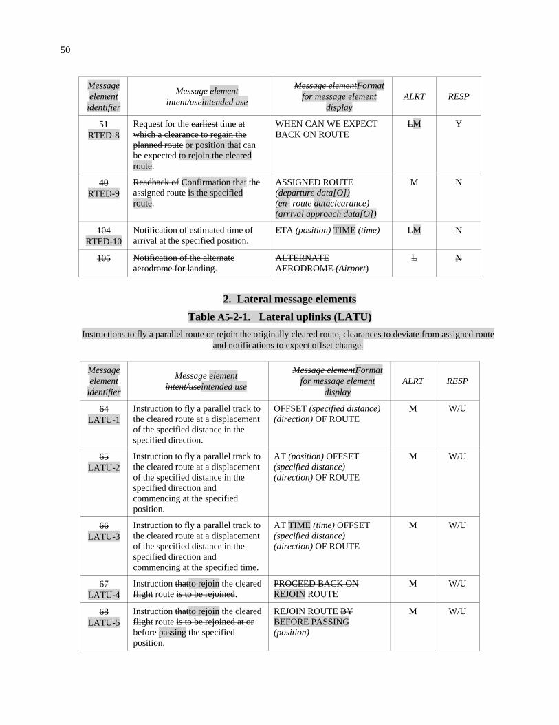
50
Message
element
identifier
Message element
intent/useintended use
Message elementFormat
for message element
display
ALRT RESP
51
RTED-8
Request for the earliest time at
which a clearance to regain the
planned route or position that can
be expected to rejoin the cleared
route.
WHEN CAN WE EXPECT
BACK ON ROUTE
LM Y
40
RTED-9
Readback of Confirmation that the
assigned route is the specified
route.
ASSIGNED ROUTE
(departure data[O])
(en- route dataclearance)
(arrival approach data[O])
M N
104
RTED-10
Notification of estimated time of
arrival at the specified position.
ETA (position) TIME (time) LM N
105
Notification of the alternate
aerodrome for landing.
ALTERNATE
AERODROME (Airport)
L N
2. Lateral message elements
Table A5-2-1. Lateral uplinks (LATU)
Instructions to fly a parallel route or rejoin the originally cleared route, clearances to deviate from assigned route
and notifications to expect offset change.
Message
element
identifier
Message element
intent/useintended use
Message elementFormat
for message element
display
ALRT RESP
64
LATU-1
Instruction to fly a parallel track to
the cleared route at a displacement
of the specified distance in the
specified direction.
OFFSET (specified distance)
(direction) OF ROUTE
M W/U
65
LATU-2
Instruction to fly a parallel track to
the cleared route at a displacement
of the specified distance in the
specified direction and
commencing at the specified
position.
AT (position) OFFSET
(specified distance)
(direction) OF ROUTE
M W/U
66
LATU-3
Instruction to fly a parallel track to
the cleared route at a displacement
of the specified distance in the
specified direction and
commencing at the specified time.
AT TIME (time) OFFSET
(specified distance)
(direction) OF ROUTE
M W/U
67
LATU-4
Instruction thatto rejoin the cleared
flight route is to be rejoined.
PROCEED BACK ON
REJOIN ROUTE
M W/U
68
LATU-5
Instruction thatto rejoin the cleared
flight route is to be rejoined at or
before passing the specified
position.
REJOIN ROUTE BY
BEFORE PASSING
(position)
M W/U

51
Message
element
identifier
Message element
intent/useintended use
Message elementFormat
for message element
display
ALRT RESP
69
LATU-6
Instruction that to rejoin the
cleared flight route is to be
rejoined at or before the specified
time.
REJOIN ROUTE BY
BEFORE TIME (time)
M W/U
70
LATU-7
Notification that a clearance may
be issued to enable the aircraft to
rejoin the cleared route at or before
passing the specified position.
EXPECT BACK ON ROUTE
BY BEFORE PASSING
(position)
LM R
71
LATU-8
Notification that a clearance may
be issued to enable the aircraft to
rejoin the cleared route at or before
the specified time.
EXPECT BACK ON ROUTE
BY BEFORE TIME (time)
LM R
72
LATU-9
Instruction to resume own
navigation following a period of
tracking or heading clearances.
May be used in conjunction with
an instruction on how or where to
rejoin the cleared route.
RESUME OWN
NAVIGATION
M W/U
82
LATU-
10
Approval Instruction allowing
deviation to deviate up to the
specified distance(s) from the
cleared route in the specified
direction(s).
CLEARED TO DEVIATE
UP TO (specified distance)
(directionlateral deviation)
OF ROUTE
M W/U
94
LATU-
11
Instruction to turn left or right as
specified on to the specified
heading.
TURN (direction) HEADING
(degrees)
M W/U
95
LATU-
12
Instruction to turn left or right as
specified on to the specified track.
TURN (direction) GROUND
TRACK (degrees)
M W/U
215
LATU-
13
Instruction to turn a the specified
number of degrees left or right.
TURN (direction) (number of
degrees) DEGREES
M W/U
96
LATU-
14
Instruction to continue to fly on the
cupresent heading.
CONTINUE PRESENT
HEADING
M W/U
97
LATU-
15
Instruction to fly on the specified
heading from upon reaching the
specified position.
AT (position) FLY
HEADING (degrees)
M W/U
190
LATU-
16
Instruction to fly on the specified
heading.
FLY HEADING (degrees) M W/U

52
Message
element
identifier
Message element
intent/useintended use
Message elementFormat
for message element
display
ALRT RESP
243
LATU-
17
Instruction to report when the
aircraft is clear of adverse
meteorological conditions, and a
clearance to regain cleared flight
route can be accepted weather.
REPORT CLEAR OF
WEATHER
LM W/U
127
LATU-
18
Instruction to report when the
aircraft is back on the cleared
route.
REPORT BACK ON ROUTE LM W/U
130
LATU-
19
Instruction to report when the
aircraft has passed upon passing
the specified position.
REPORT PASSING
(position)
LM W/U
152 Instruction to report the earliest
time or position when the specified
offset track can be accepted.
WHEN CAN YOU ACCEPT
(specified distance)
(direction) OFFSET
L Y
221 Instruction to stop turn at the
specified heading prior to reaching
the previously assigned heading.
STOP TURN HEADING
(degrees)
M W/U
98 Instruction to turn immediately left
or right as specified on to the
specified heading.
IMMEDIATELY TURN
(direction) HEADING
(degrees)
H W/U
145 Instruction to report the present
heading.
REPORT HEADING M Y
Table A5-2-2. Lateral downlinks (LATD)
Requests to offset or deviate from route.
Message
element
identifier
Message element
intent/useintended use
Message elementFormat
for message element
display
ALR
T
RES
P
15
LATD-1
Request that for a parallel track,
offset from the cleared track by
route at a displacement of the
specified distance in the specified
direction, be approved.
REQUEST OFFSET
(specified distance)
(direction) OF ROUTE
LM Y
16 Request that a parallel track, offset
from the cleared track by the
specified distance in the specified
direction, be approved from the
specified position.
AT (position) REQUEST
OFFSET (specified distance)
(direction) OF ROUTE
L Y

53
Message
element
identifier
Message element
intent/useintended use
Message elementFormat
for message element
display
ALR
T
RES
P
17 Request that a parallel track, offset
from the cleared track by the
specified distance in the specified
direction, be approved from the
specified time.
AT (time) REQUEST
OFFSET (specified distance)
(direction) OF ROUTE
L Y
26 Request for a weather deviation to
the specified position via the
specified route.
REQUEST WEATHER
DEVIATION TO (position)
VIA (route clearance)
M Y
27
LATD-2
Request for a weather deviation up
to the specified distance(s) off track
in the specified direction(s).
REQUEST WEATHER
DEVIATION UP TO
(specified distance)
(directionlateral deviation)
OF ROUTE
M Y
35 Notification of the present heading
in degrees.
PRESENT HEADING
(degrees)
L N
114
LATD-3
Notification Report indicating that
the aircraft is clear of weather and is
able to accept a clearance to regain
cleared flight route.
CLEAR OF WEATHER M N
41
LATD-4
The aircraft has regained Report
indicating that the cleared route has
been rejoined.
BACK ON ROUTE M N
59
LATD-5
Notification that the aircraft is
Report indicating diverting to the
specified position via the specified
route due to an urgent need, which
may be sent without any previous
coordination done with ATC.
DIVERTING TO (position)
VIA (en-route dataclearance)
(arrival approach data[O])
HM Y
60
LATD-6
Notification Report indicating that
the aircraft is deviating offsetting to
a parallel track at the specified
distance in the specified direction
off from the cleared route and
maintaining a parallel track due to
an urgent need.
OFFSETTING (specified
distance) (direction) OF
ROUTE
HM Y
80
LATD-7
Notification that the aircraft is
Report indicating deviating up to the
specified distance from the cleared
route or degrees in the specified
direction due to an urgent need from
the cleared route.
DEVIATING UP TO
(specified deviation distance)
(direction) OF ROUTE
HM Y
31
LATD-8
Notification of Report indicating
passing the specified position.
PASSING (position) LM N

54
Message
element
identifier
Message element
intent/useintended use
Message elementFormat
for message element
display
ALR
T
RES
P
85 We can accept a parallel track offset
the specified distance in the
specified direction at the specified
time.
WE CAN ACCEPT (specified
distance) (direction) AT
(time)
L N
86 We cannot accept a parallel track
offset the specified distance in the
specified direction.
WE CANNOT ACCEPT
(specified distance)
(direction)
L N
117 We can accept a parallel track offset
the specified distance in the
specified direction at the specified
position.
WE CAN ACCEPT (specified
distance) (direction) AT
(position)
L N
3. Level message elements
Table A5-3-1. Level uplinks (LVLU)
Instructions to change the assigned level, responses to level request,
modifications or restrictions to level clearances, and notifications to expect level clearance.
Message
element
identifier
Message element
intent/useintended use
Message elementFormat
for message element
display
ALRT RESP
6 Notification that a level change
instruction should be expected.
EXPECT (level) L R
7
LVLU-1
Notification that an instruction
should may be expected for the
aircraft to commence climb at the
specified time.
EXPECT CLIMB HIGHER
AT TIME (time)
LM R
8
LVLU-2
Notification that an instruction
should may be expected for the
aircraft to commence climb at the
specified position.
EXPECT CLIMB HIGHER
AT (position)
LM R
9
LVLU-3
Notification that an instruction
should may be expected for the
aircraft to commence descent at the
specified time.
EXPECT DESCENT
LOWER AT TIME (time)
LM R
10
LVLU-4
Notification that an instruction
should may be expected for the
aircraft to commence descent at the
specified position.
EXPECT DESCENT
LOWER AT (position)
LM R
11 Notification that an instruction
should be expected for the aircraft to
commence cruise climb at the
specified time.
EXPECT CRUISE CLIMB
AT (time)
L R
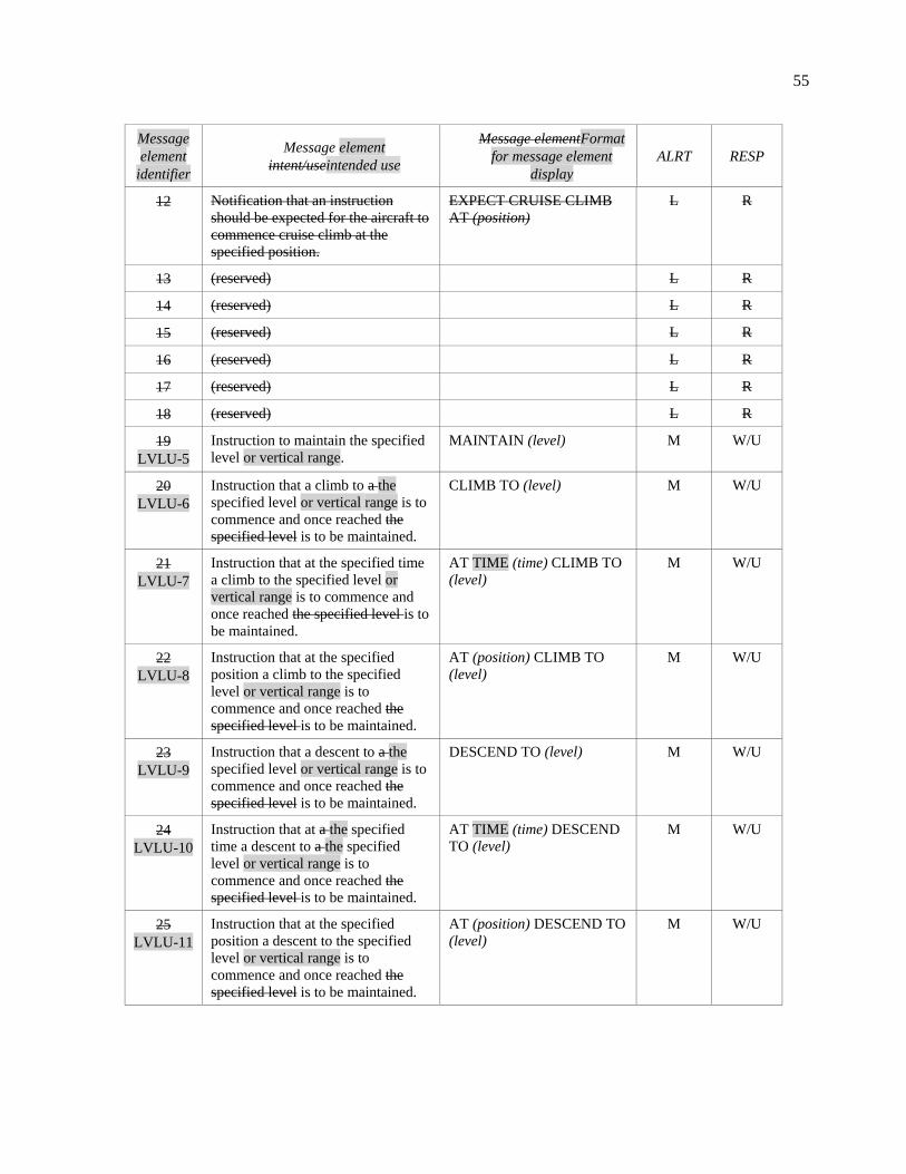
55
Message
element
identifier
Message element
intent/useintended use
Message elementFormat
for message element
display
ALRT RESP
12 Notification that an instruction
should be expected for the aircraft to
commence cruise climb at the
specified position.
EXPECT CRUISE CLIMB
AT (position)
L R
13 (reserved) L R
14 (reserved) L R
15 (reserved) L R
16 (reserved) L R
17 (reserved) L R
18 (reserved) L R
19
LVLU-5
Instruction to maintain the specified
level or vertical range.
MAINTAIN (level) M W/U
20
LVLU-6
Instruction that a climb to a the
specified level or vertical range is to
commence and once reached the
specified level is to be maintained.
CLIMB TO (level) M W/U
21
LVLU-7
Instruction that at the specified time
a climb to the specified level or
vertical range is to commence and
once reached the specified level is to
be maintained.
AT TIME (time) CLIMB TO
(level)
M W/U
22
LVLU-8
Instruction that at the specified
position a climb to the specified
level or vertical range is to
commence and once reached the
specified level is to be maintained.
AT (position) CLIMB TO
(level)
M W/U
23
LVLU-9
Instruction that a descent to a the
specified level or vertical range is to
commence and once reached the
specified level is to be maintained.
DESCEND TO (level) M W/U
24
LVLU-10
Instruction that at a the specified
time a descent to a the specified
level or vertical range is to
commence and once reached the
specified level is to be maintained.
AT TIME (time) DESCEND
TO (level)
M W/U
25
LVLU-11
Instruction that at the specified
position a descent to the specified
level or vertical range is to
commence and once reached the
specified level is to be maintained.
AT (position) DESCEND TO
(level)
M W/U

56
Message
element
identifier
Message element
intent/useintended use
Message elementFormat
for message element
display
ALRT RESP
26
LVLU-12
Instruction that a climb is to
commence at a rate be completed
such that the specified level is
reached at or before the specified
time. When this message element is
not concatenated with another
vertical clearance, the level specified
is the assigned level which is to be
maintained.
CLIMB TO REACH (level
single) BY BEFORE TIME
(time)
M W/U
27
LVLU-13
Instruction that a climb is to
commence at a rate be completed
such that the specified level is
reached at or before passing the
specified position. When this
message element is not concatenated
with another vertical clearance, the
level specified is the assigned level
which is to be maintained.
CLIMB TO REACH (level
single) BY BEFORE
PASSING (position)
M W/U
28
LVLU-14
Instruction that a descent is to
commence at a rate be completed
such that the specified level is
reached at or before the specified
time. When this message element is
not concatenated with another
vertical clearance, the level specified
is the assigned level which is to be
maintained.
DESCEND TO REACH
(level single) BY BEFORE
TIME (time)
M W/U
29
LVLU-15
Instruction that a descent is to
commence at a rate be completed
such that the specified level is
reached at or before passing the
specified position. When this
message element is not concatenated
with another vertical clearance, the
level specified is the assigned level
which is to be maintained.
DESCEND TO REACH
(level single) BY BEFORE
PASSING (position)
M W/U
30 Instruction that a level within the
defined vertical range specified is to
be maintained.
MAINTAIN BLOCK (level)
TO (level)
M W/U
31 Instruction that a climb to a level
within the vertical range defined is
to commence.
CLIMB TO AND
MAINTAIN BLOCK (level)
TO (level)
M W/U
32 Instruction that a descent to a level
within the vertical range defined is
to commence.
DESCEND TO AND
MAINTAIN BLOCK (level)
TO (level)
M W/U
33 (reserved) L Y

57
Message
element
identifier
Message element
intent/useintended use
Message elementFormat
for message element
display
ALRT RESP
34 Instruction that a cruise climb to the
specified level is to commence and
continue and, once reached, the
specified level is to be maintained.
CRUISE CLIMB TO (level) M W/U
35 Instruction to be used in conjunction
with an associated level instruction
indicating that a cruise climb can
commence once above the specified
level.
WHEN ABOVE (level)
COMMENCE CRUISE
CLIMB
M W/U
36 Instruction that the climb to the
specified level should be made at the
aircraft’s best rate.
EXPEDITE CLIMB TO
(level)
M W/U
37 Instruction that the descent to the
specified level should be made at the
aircraft’s best rate.
EXPEDITE DESCENT TO
(level)
M W/U
38 Urgent instruction to immediately
climb to the specified level and,
once reached, the specified level is
to be maintained.
IMMEDIATELY CLIMB
TO (level)
H W/U
39 Urgent instruction to immediately
descend to the specified level and,
once reached, the specified level is
to be maintained.
IMMEDIATELY DESCEND
TO (level)
H W/U
40 (reserved) L Y
41 (reserved) L Y
192
Instruction that a change of level is
to continue, but at a rate such that
the specified level is reached at or
before the specified time.
REACH (Level) BY (Time) M W/U
209
Instruction that a change of level is
to continue, but at a rate such that
the specified level is reached at or
before the specified position.
REACH (Level) BY
(Position)
M W/U
219
LVLU-16
Instruction to stop the climb at the
specified level and, once reached,
this level is to be maintained. The
specified level will be below the
previously assigned level. This
instruction should only be issued
when the controller can confirm that
the previously assigned level has not
yet been reached.
STOP CLIMB AT (Llevel
single)
M W/U

58
Message
element
identifier
Message element
intent/useintended use
Message elementFormat
for message element
display
ALRT RESP
220
LVLU-17
Instruction to stop the descent at the
specified level and, once reached,
this level is to be maintained. The
specified level will be above the
previously assigned level. This
instruction should only be issued
when the controller can confirm that
the previously assigned level has not
yet been reached.
STOP DESCENT AT (Llevel
single)
M W/U
171
LVLU-18
Instruction to climb at not less than
the specified rate or greater.
CLIMB AT (vertical rate)
MINIMUMOR GREATER
M W/U
172
LVLU-19
Instruction to climb at not above the
specified rate or less.
CLIMB AT (vertical rate)
MAXIMUMOR LESS
M W/U
173
LVLU-20
Instruction to descend at not less
than the specified rate or greater.
DESCEND AT (vertical rate)
MINIMUMOR GREATER
M W/U
174
LVLU-21
Instruction to descend at not above
the specified rate or less.
DESCEND AT (vertical rate)
MAXIMUMOR LESS
M W/U
LVLU-22 Notification that a clearance may be
issued for the aircraft to commence a
climb to the specified level at the
specified number of minutes after
departure.
EXPECT (level single)
(number of minutes) AFTER
DEPARTURE
M R
128
LVLU-23
Instruction to report when the
aircraft has vacated upon leaving the
specified level that has either been
maintained or passed through on
climb or descent.
REPORT LEAVING (level
single)
LM W/U
129
LVLU-24
Instruction to report when the
aircraft is maintaining level flight at
the specified level.
REPORT MAINTAINING
(level single)
LM W/U
133
LVLU-25
Instruction to report the present
level.
REPORT PRESENT LEVEL M Y
180
LVLU-26
Instruction to report when the
aircraft is within upon reaching the
specified vertical range.
REPORT REACHING
BLOCK (level single) TO
(level single)
LM W/U
135
LVLU-27
Instruction Request to confirm the
currently assigned level.
CONFIRM ASSIGNED
LEVEL
LM Y
231
LVLU-28
Instruction Request to indicate
provide the pilot’s preferred level.
STATE ADVISE
PREFERRED LEVEL
LM Y

59
Message
element
identifier
Message element
intent/useintended use
Message elementFormat
for message element
display
ALRT RESP
232
LVLU-29
Instruction Request to indicate
provide the pilot’s preferred time
and/or position to commence
descent to the aerodrome of intended
arrival.
STATEADVISE TOP OF
DESCENT
L Y
200
Instruction used in conjunction with
a level clearance to report
maintaining the level assigned
REPORT MAINTAINING L W/U
148
LVLU-30
Request for the earliest time or
position at which when the specified
level can be accepted.
WHEN CAN YOU ACCEPT
(level single)
LM Y
149
LVLU-31
Instruction Request to report
indicate whether or not the specified
level can be accepted at the specified
position.
CAN YOU ACCEPT (level
single) AT (position)
LM A/N
150
LVLU-32
Instruction Request to report
indicate whether or not the specified
level can be accepted at the specified
time.
CAN YOU ACCEPT (level
single) AT TIME (time)
LM A/N
175 (reserved) L W/U
185 (reserved) M W/U
186 (reserved) M W/U
236 Instruction to leave controlled
airspace.
LEAVE CONTROLLED
AIRSPACE
M W/U
217 Instruction to report that the aircraft
has landed.
REPORT ARRIVAL M Y
Table A5-3-2. Level downlinks (LVLD)
Requests to change the assigned altitude and inquiries when level change can be expected.
Message
element
identifier
Message element
intent/useintended use
Message elementFormat
for message element
display
ALRT RESP
6
LVLD-1
Request to fly at the specified
level or vertical range.
REQUEST (level) LM Y
7 Request to fly at a level within the
specified vertical range.
REQUEST BLOCK (level)
TO (level)
L Y
8 Request to cruise climb to the
specified level.
REQUEST CRUISE CLIMB
TO (level)
L Y
9
LVLD-2
Request to for a climb to the
specified level or vertical range.
REQUEST CLIMB TO
(level)
LM Y

60
Message
element
identifier
Message element
intent/useintended use
Message elementFormat
for message element
display
ALRT RESP
10
LVLD-3
Request to descend for a descent
to the specified level or vertical
range.
REQUEST DESCENT TO
(level)
LM Y
11
LVLD-4
Request that at the specified
position for a climb/descent to the
specified level be approved or
vertical range to commence at the
specified position.
AT (position) REQUEST
CLIMB TO (level)
LM Y
12 Request that at the specified
position a descent to the specified
level be approved.
AT (position) REQUEST
DESCENT TO (level)
L Y
13
LVLD-5
Request that at the specified time
for a climb/descent to the
specified level be approved or
vertical range to commence at the
specified time.
AT TIME (time) REQUEST
CLIMB TO (level)
LM Y
14 Request that at the specified time
a descent to the specified level be
approved.
AT (time) REQUEST
DESCENT TO (level)
L Y
52
LVLD-6
Request for the earliest time at
which or position that a clearance
to descend descent can be
expected.
WHEN CAN WE EXPECT
LOWER LEVEL
LM Y
53
LVLD-7
Request for the earliest time at
which or position that a clearance
to climb can be expected.
WHEN CAN WE EXPECT
HIGHER LEVEL
LM Y
54 Request for the earliest time at
which a clearance to cruise climb
to the specified level can be
expected.
WHEN CAN WE EXPECT
CRUISE CLIMB TO (level)
L Y
28
LVLD-8
Notification of Report indicating
leaving the specified level.
LEAVING (level single) LM N
37
LVLD-9
Notification Report indicating that
the aircraft is maintaining the
specified level is being
maintained.
MAINTAINING (level
single)
LM N
69 Request that a descent be
approved on a see-and-avoid
basis.
REQUEST VMC DESCENT L Y
76
LVLD-10
Notification that the aircraft has
reached a level within Report
indicating reaching the specified
vertical range.
REACHING BLOCK (level
single) TO (level single)
LM N
32 Notification of the present level. PRESENT LEVEL (level) L N

61
Message
element
identifier
Message element
intent/useintended use
Message elementFormat
for message element
display
ALRT RESP
38
LVLD-11
Readback of Confirmation that the
assigned level or vertical range is
the specified level or vertical
range.
ASSIGNED LEVEL (level) M N
72 (reserved) L N
77 Readback of the assigned vertical
range.
ASSIGNED BLOCK (level)
TO (level)
M N
106
LVLD-12
Notification of Report indicating
that the aircraft’s preferred level is
the specified level.
PREFERRED LEVEL (level
single)
LM N
29
LVLD-13
Notification of Report indicating
climbing to the specified level.
CLIMBING TO (level single) LM N
30
LVLD-14
Notification of Report indicating
descending to the specified level.
DESCENDING TO (level
single)
LM N
81
LVLD-15
We can accept Indication that the
specified level can be accepted at
the specified time.
WE CAN ACCEPT (level
single) AT TIME (time)
LM N
115
LVLD-16
We can accept Indication that the
specified level can be accepted at
the specified position.
WE CAN ACCEPT (level
single) AT (position)
LM N
82
LVLD-17
We cannot accept Indication that
the specified level cannot be
accepted.
WE CANNOT ACCEPT
(level single)
LM N
87 Request for the earliest time at
which a clearance to climb to the
specified level can be expected.
WHEN CAN WE EXPECT
CLIMB TO (level)
L Y
88 Request for the earliest time at
which a clearance to descend to
the specified level can be
expected.
WHEN CAN WE EXPECT
DESCENT TO (level)
L Y
109 Notification of the preferred time
to commence descent for
approach.
TOP OF DESCENT (time) L N
110 Notification of the preferred
position to commence descent for
approach.
TOP OF DESCENT
(position)
L N
111
LVLD-18
Notification of the preferred time
and position to commence descent
for approach.
TOP OF DESCENT (time)
(position) TIME (time)
LM N

62
4. Crossing constraint message elements
Table A5-4-1. Crossing constraint uplinks (CSTU)
Instructions to cross a specified position at a specified altitude, time, and/or speed, instruction to cancel a crossing
constraint.
Message
element
identifier
Message element
intent/useintended use
Message elementFormat
for message element
display
ALRT RESP
42 (reserved) L R
43 (reserved) L R
44 (reserved) L R
45 (reserved) L R
46
CSTU-1
I Instruction that the specified
position is to be crossed at the
specified level. This may require
or within the aircraft to modify its
climb or descent profile specified
vertical range.
CROSS (position) AT (level) M W/U
47
CSTU-2
Instruction that the specified
position is to be crossed at or
above the specified level.
CROSS (position) AT OR
ABOVE (level single)
M W/U
48
CSTU-3
Instruction that the specified
position is to be crossed at or
below the specified level.
CROSS (position) AT OR
BELOW (level single)
M W/U
49 Instruction that the specified
position is to be crossed at the
specified level and that level is to
be maintained when reached.
CROSS (position) AT AND
MAINTAIN (level)
M W/U
50 Instruction that the specified
position is to be crossed at a level
between the specified levels.
CROSS (position)
BETWEEN (level) AND
(level)
M W/U
51
CSTU-4
Instruction that the specified
position is to be crossed at the
specified time.
CROSS (position) AT TIME
(time)
M W/U
52
CSTU-5
Instruction that the specified
position is to be crossed at or
before the specified time.
CROSS (position) AT OR
BEFORE TIME (time)
M W/U
53
CSTU-6
Instruction that the specified
position is to be crossed at or after
the specified time.
CROSS (position) AT OR
AFTER TIME (time)
M W/U
54
CSTU-7
Instruction that the specified
position is to be crossed at a time
between the specified times.
CROSS (position)
BETWEEN TIME (time)
AND TIME (time)
M W/U

63
Message
element
identifier
Message element
intent/useintended use
Message elementFormat
for message element
display
ALRT RESP
55
CSTU-8
Instruction that the specified
position is to be crossed at the
specified speed and the specified
speed is to be maintained until
further advised.
CROSS (position) AT (speed) M W/U
56
CSTU-9
Instruction that the specified
position is to be crossed at a speed
equal to or less than the specified
speed and the specified speed or
less is to be maintained until
further advised.
CROSS (position) AT (speed)
OR LESS THAN (speed)
M W/U
57
CSTU-10
Instruction that the specified
position is to be crossed at a speed
equal to or greater than the
specified speed and the specified
speed or greater is to be
maintained until further advised.
CROSS (position) AT (speed)
OR GREATER THAN
(speed)
M W/U
58
CSTU-11
Instruction that the specified
position is to be crossed at the
specified time and at the level or
within the vertical range as
specified level.
CROSS (position) AT TIME
(time) AT (level)
M W/U
59
CSTU-12
Instruction that the specified
position is to be crossed at or
before the specified time and at the
level or within the vertical range as
specified level.
CROSS (position) AT OR
BEFORE TIME(time) AT
(level)
M W/U
60
CSTU-13
Instruction that the specified
position is to be crossed at or after
the specified time and at the level
or within the vertical range as
specified level.
CROSS (position) AT OR
AFTER TIME(time) AT
(level)
M W/U
61
CSTU-14
Instruction that the specified
position is to be crossed at the
level or within the vertical range,
as specified level, and at the
specified speed, and the level and
speed are to be maintained.
CROSS (position) AT AND
MAINTAIN (level) AT
(speed)
M W/U
62 Instruction that at the specified
time the specified position is to be
crossed at the specified level and
the level is to be maintained.
AT (time) CROSS (position)
AT AND MAINTAIN (level)
M W/U

64
Message
element
identifier
Message element
intent/useintended use
Message elementFormat
for message element
display
ALRT RESP
63
CSTU-15
Instruction that at the specified
time the specified position is to be
crossed at the specified time at the
level or within the vertical range,
as specified, and at the specified
speed, and the level and speed are
to be maintained.
AT (time) CROSS (position)
AT TIME (time) AT AND
MAINTAIN (level) AT
(speed)
M W/U
5. Speed message elements
Table A5-5-1. Speed uplinks (SPDU)
Instructions to change or maintain speed, notifications to expect speed change.
Message
element
identifier
Message element
intent/useintended use
Message elementFormat
for message element
display
ALRT RESP
100
SPDU-1
Notification that a speed
instruction may be issued to be
effective take effect at the
specified time.
EXPECT SPEED CHANGE
AT TIME (time) EXPECT
(speed)
LM R
101
SPDU-2
Notification that a speed
instruction may be issued to be
effective take effect at the
specified position.
AT (position) EXPECT
(speed) SPEED CHANGE
AT (position)
LM R
102
SPDU-3
Notification that a speed
instruction may be issued to be
effective take effect at the
specified level.
EXPECT SPEED CHANGE
AT (level single) EXPECT
(speed)
LM R
103 Notification that a speed range
instruction may be issued to be
effective at the specified time.
AT (time) EXPECT (speed)
TO (speed)
L R
104 Notification that a speed range
instruction may be issued to be
effective at the specified position.
AT (position) EXPECT
(speed) TO (speed)
L R
105 Notification that a speed range
instruction may be issued to be
effective at the specified level.
AT (level) EXPECT (speed)
TO (speed)
L R
106
SPDU-4
Instruction that to maintain the
specified speed is to be
maintained.
MAINTAIN (speed) M W/U
188
Instruction that after passing the
specified position the specified
speed is to be maintained.
AFTER PASSING (Position)
MAINTAIN (Speed)
M W/U

65
Message
element
identifier
Message element
intent/useintended use
Message elementFormat
for message element
display
ALRT RESP
107
SPDU-5
Instruction that to maintain the
present speed is to be maintained.
MAINTAIN PRESENT
SPEED
M W/U
108
SPDU-6
Instruction that to maintain the
specified speed or a greater speed
is to be maintained.
MAINTAIN (speed) OR
GREATER
M W/U
109
SPDU-7
Instruction that to maintain the
specified speed or a lesser speed is
to be maintained less.
MAINTAIN (speed) OR
LESS
M W/U
110
SPDU-8
Instruction that a speed within to
maintain the specified speed range
is to be maintained.
MAINTAIN (speed) TO
(speed)
M W/U
111
SPDU-9
Instruction that the present speed is
to be increased to the specified
speed and maintained until further
advised.
INCREASE SPEED TO
(speed)
M W/U
112
SPDU-10
Instruction that the present speed is
to be increased to the specified
speed or greater, and maintained at
or above the specified speed until
further advised.
INCREASE SPEED TO
(speed) OR GREATER
M W/U
113
SPDU-11
Instruction that the present speed is
to be reduced to the specified
speed and maintained until further
advised.
REDUCE SPEED TO (speed) M W/U
114
SPDU-12
Instruction that the present speed is
to be reduced to the specified
speed, or less, and maintained at or
below the specified speed until
further advised.
REDUCE SPEED TO (speed)
OR LESS
M W/U
115 Instruction that the specified speed
is not to be exceeded.
DO NOT EXCEED (speed) M W/U
116
SPDU-13
Instruction that the aircraft’s to
resume a normal speed be
resumed. The aircraft no longer
needs to comply with a previously
issued speed restriction(s) are
cancelled.
RESUME NORMAL SPEED M W/U
189
Instruction that the present speed is
to be changed to the specified
speed.
ADJUST SPEED TO (Speed) M W/U
222
SPDU-14
NotificationIndication that the
aircraft may keep its preferred
speed may be flown without
restriction.
NO SPEED RESTRICTION LM R

66
Message
element
identifier
Message element
intent/useintended use
Message elementFormat
for message element
display
ALRT RESP
223
Instruction to reduce present speed
to the minimum safe approach
speed.
REDUCE TO MINIMUM
APPROACH SPEED
M W/U
134
SPDU-15
Instruction Request to report the
requested speed defined by the
specified speed type(s).
REPORT (speed types)
(speed type) (speed type)
SPEED
M Y
136
SPDU-16
Instruction Request to confirm the
currently assigned speed.
CONFIRM ASSIGNED
SPEED
LM Y
151
SPDU-17
Instruction to report Request for
the earliest time or position when
the specified speed can be
accepted.
WHEN CAN YOU ACCEPT
(speed)
LM Y
Table A5-5-2. Speed downlinks (SPDD)
Requests related to speed and inquiries when speed change can be expected.
Message
element
identifier
Message element
intent/useintended use
Message elementFormat
for message element
display
ALRT RESP
18
SPDD-1
Request to fly at for the specified
speed.
REQUEST (speed) LM Y
19 Request to fly within the specified
speed range.
REQUEST (speed) TO
(speed)
L Y
49
SPDD-2
Request for the earliest time at
which a clearance to or position
that the specified speed can be
expected.
WHEN CAN WE EXPECT
(speed)
LM Y
50 Request for the earliest time at
which a clearance to a speed within
the specified range can be
expected.
WHEN CAN WE EXPECT
(speed) TO (speed)
L Y
113
SPDD-3
Notification of the requested speed
Report indicating the speed defined
by the specified speed types is the
specified speed.
(speed types) (speed type)
(speed type) SPEED (speed)
LM N
34 Notification of the present speed. PRESENT SPEED (speed) L N
39
SPDD-4
Readback of Confirmation that the
assigned speed is the specified
speed.
ASSIGNED SPEED (speed) M N
83
SPDD-5
We can accept Indication that the
specified speed can be accepted at
the specified time.
WE CAN ACCEPT (speed)
AT TIME (time)
LM N

67
Message
element
identifier
Message element
intent/useintended use
Message elementFormat
for message element
display
ALRT RESP
116
We can accept the specified speed
at the specified position.
WE CAN ACCEPT (Speed)
AT (Position)
L N
84
SPDD-6
We cannot accept Indication that
the specified speed cannot be
accepted.
WE CANNOT ACCEPT
(speed)
LM N
6. Air Traffic Advisory message elements
Table A5-6-1. Air traffic advisory uplinks (ADVU)
Advisories related to the use CPDLC, ADS-C and surveillance services.
Message
element
identifier
Message element
intent/useintended use
Message elementFormat
for message element
display
ALRT RESP
153 ATS advisory that the altimeter
setting should be the specified
setting.
ALTIMETER (altimeter) L R
213
ADVU-1
ATS Advisory that providing the
specified altimeter setting for
relates to the specified facility.
(facility Designation)
ALTIMETER (altimeter
setting)
LM R
154
ADVU-2
ATS Advisory that the radar ATS
surveillance service is terminated.
RADAR SURVEILLANCE
SERVICE TERMINATED
LM R
191
ATS Advisory that the aircraft is
entering airspace in which no air
traffic services are provided and
all existing air traffic services are
terminated.
ALL ATS TERMINATED M R
155
ADVU-3
ATS Advisory that radar contact
ATS surveillance service has
been established at the. A
position may be specified
position.
RADAR CONTACT
(position)IDENTIFIED
(position[O])
M R
210 ATS advisory that the aircraft has
been identified on radar and/or
ADS-B at the specified position.
IDENTIFIED (position) M R
156
ADVU-4
ATS Advisory that radar ATS
surveillance contact has been lost.
RADAR CONTACT
IDENTIFICATION LOST
M R
193 Notification that radar and/or
ADS-B identification has been
lost.
IDENTIFICATION LOST M R

68
Message
element
identifier
Message element
intent/useintended use
Message elementFormat
for message element
display
ALRT RESP
158
ADVU-5
ATS Advisory that the ATIS
information identified by the
specified code is the current ATIS
information code is as specified.
ATIS (atisATIS code) LM R
182 Instruction to report the
identification code of the last
ATIS received.
CONFIRM ATIS CODE L Y
212 ATS advisory that the specified
ATIS information at the specified
airport is current.
(facility designation) ATIS
(atis code) CURRENT
L R
214
ATS Advisory that indicates the
RVR value for the specified
runway.
RVR RUNWAY (Runway)
(Rvr)
M R
224
ATS Advisory that no delay is
expected.
NO DELAY EXPECTED L R
225
ATS advisory that the expected
delay has not been determined.
DELAY NOT
DETERMINED
L R
226
ATS advisory that the aircraft
may expect to be cleared to
commence its approach procedure
at the specified time.
EXPECTED APPROACH
TIME (Time)
L R
237
ADVU-6
Indicates that the Advisory to
request cannot be responded to by
the current unit and that it should
be requested from again with the
next ATC unit.
REQUEST AGAIN WITH
NEXT ATC UNIT
LM N
ADVU-7 Advisory of traffic significant to
the flight.
TRAFFIC IS (traffic
description)
M R
ADVU-8 Instruction to report that the
specified traffic has been visually
sighted and passed. The
instruction may indicate the
estimated time of passing.
REPORT SIGHTING AND
PASSING OPPOSITE
DIRECTION (aircraft
type[O]) (traffic location)
(ETP time[O])
M W/U
123
ADVU-9
Instruction that to select the
specified code (SSR code) is to be
selected..
SQUAWK (SSR code) M W/U
124
ADVU-10
Instruction that the to disable SSR
transponder responses are to be
disabled.
STOP SQUAWK M W/U
239
ADVU-11
Instruction that the to stop ADS-B
transmissions are to be
terminated.
STOP ADS-B
TRANSMISSION
M W/U

69
Message
element
identifier
Message element
intent/useintended use
Message elementFormat
for message element
display
ALRT RESP
125
ADVU-12
Instruction that the to include
level information in SSR
transponder responses should
include level information.
SQUAWK MODE CHARLIE
C
M W/U
126
ADVU-13
Instruction that the to stop
including level information in
SSR transponder responses
should no longer include level
information.
STOP SQUAWK MODE
CHARLIE C
M W/U
144
ADVU-14
Instruction Request to report
confirm the selected (SSR) code.
CONFIRM SQUAWK CODE LM Y
179
ADVU-15
Instruction that the “ident”
function on the SSR transponder
is to be actuated.
SQUAWK IDENT M W/U
ADVU-16 Instruction to activate the ADS-C
capability.
ACTIVATE ADS-C M W/U
ADVU-17 Instruction to transmit voice
position reports, as specified, due
to ADS-C being out of service.
ADS-C OUT OF SERVICE
REVERT TO VOICE
POSITION REPORTS
M W/U
ADVU-18 Instruction to intermediary
aircraft to relay the specified
message to the specified aircraft
on the specified frequency, when
provided.
RELAY TO (aircraft
identification) (unit name)
(relay text) (frequency[O])
M W/U
ADVU-19 Request to check the aircraft
lateral position, level or speed due
to the ATC unit detecting a
deviation from the clearance.
(deviation type) DEVIATION
DETECTED. VERIFY AND
ADVISE
M W/U
240 Instruction that the ADS-B
transmissions should include level
information.
TRANSMIT ADS-B
ALTITUDE
M W/U
241 Instruction that the ADS-B
transmissions should no longer
include level information.
STOP ADS-B ALTITUDE
TRANSMISSION
M W/U
242 Instruction that the “ident”
function of the ADS-B emitter is
to be activated.
TRANSMIT ADS-B IDENT M W/U
244 ATS advisory that the radar
and/or ADS-B service is
terminated.
IDENTIFICATION
TERMINATED
L R

70
Table A5-6-2. Air traffic advisory downlinks (ADVD)
Reports related to the application of relay procedure
Message
element
identifier
Message element
intent/useintended use
Message elementFormat
for message element
display
ALRT RESP
47
ADVD-1
Report indicating that the aircraft
is squawking the specified (SSR)
code has been selected.
SQUAWKING (SSR code) LM N
79 The code of the latest ATIS
received is as specified.
ATIS (atis code) L N
102
Used to report that an aircraft has
landed.
LANDING REPORT N N
ADVD-2 Report indicating that whether or
not traffic has been visually
sighted and if so, if it has been
passed. May provide a description
of the aircraft.
TRAFFIC (aircraft type[O])
(traffic location) (traffic
visibility)
M N
7. Voice communications message elements
Table A5-7-1. Voice communications uplinks (COMU)
Instructions to monitor or contact air traffic control on voice frequencies and instruction to check stuck microphone.
Message
element
identifier
Message element
intent/useintended use
Message elementFormat
for message element
display
ALRT RESP
117
COMU-1
Instruction that the ATS unit to
establish voice contact with the
specified ATS unit name is to be
contacted on the specified
frequency.
CONTACT (unit name)
(frequency)
M W/U
118
COMU-2
Instruction that at the specified
position the ATS unit, to establish
voice contact with the specified
ATS unit name is to be contacted
on the specified frequency.
AT (position) CONTACT
(unit name) (frequency)
M W/U
119
COMU-3
Instruction that at the specified
time the ATS unit to establish
voice contact with the specified
ATS unit name is to be contacted
on the specified frequency.
AT TIME (time) CONTACT
(unit name) (frequency)
M W/U
238
COMU-4
Notification that Advisory of the
secondary frequency is as
specified.
SECONDARY
FREQUENCY (frequency)
LM R
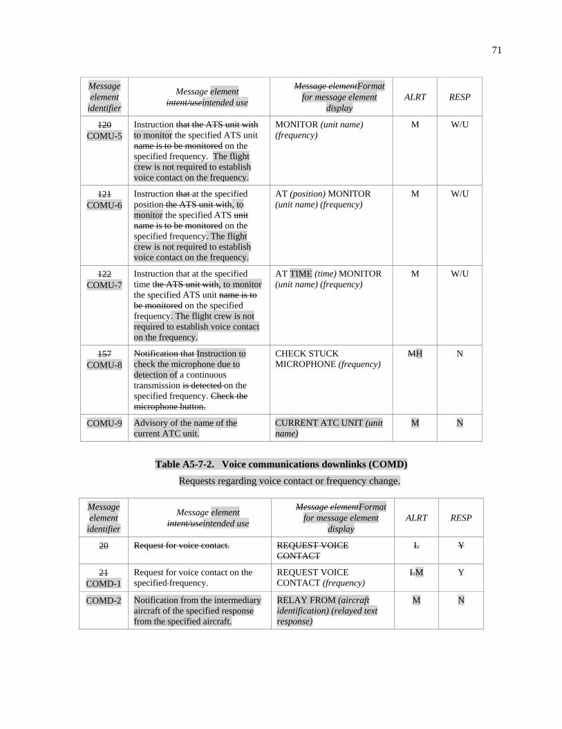
71
Message
element
identifier
Message element
intent/useintended use
Message elementFormat
for message element
display
ALRT RESP
120
COMU-5
Instruction that the ATS unit with
to monitor the specified ATS unit
name is to be monitored on the
specified frequency. The flight
crew is not required to establish
voice contact on the frequency.
MONITOR (unit name)
(frequency)
M W/U
121
COMU-6
Instruction that at the specified
position the ATS unit with, to
monitor the specified ATS unit
name is to be monitored on the
specified frequency. The flight
crew is not required to establish
voice contact on the frequency.
AT (position) MONITOR
(unit name) (frequency)
M W/U
122
COMU-7
Instruction that at the specified
time the ATS unit with, to monitor
the specified ATS unit name is to
be monitored on the specified
frequency. The flight crew is not
required to establish voice contact
on the frequency.
AT TIME (time) MONITOR
(unit name) (frequency)
M W/U
157
COMU-8
Notification that Instruction to
check the microphone due to
detection of a continuous
transmission is detected on the
specified frequency. Check the
microphone button.
CHECK STUCK
MICROPHONE (frequency)
MH N
COMU-9 Advisory of the name of the
current ATC unit.
CURRENT ATC UNIT (unit
name)
M N
Table A5-7-2. Voice communications downlinks (COMD)
Requests regarding voice contact or frequency change.
Message
element
identifier
Message element
intent/useintended use
Message elementFormat
for message element
display
ALRT RESP
20 Request for voice contact. REQUEST VOICE
CONTACT
L Y
21
COMD-1
Request for voice contact on the
specified frequency.
REQUEST VOICE
CONTACT (frequency)
LM Y
COMD-2 Notification from the intermediary
aircraft of the specified response
from the specified aircraft.
RELAY FROM (aircraft
identification) (relayed text
response)
M N

72
Message
element
identifier
Message element
intent/useintended use
Message elementFormat
for message element
display
ALRT RESP
89 The specified ATS unit is being
monitored on the specified
frequency.
MONITORING (unit name)
(frequency)
M N
8. Spacing message elements
Table A5-8-1. Spacing uplinks (SPCU)
Clearances to conduct spacing manoeuvre during en-route or arrival operations and notifications to expect spacing clearance.
Message
element
identifier
Message element
intent/useintended use
Message elementFormat
for message element
display
ALRT RESP
*
SPCU-1
ATS acknowledgement for the
pilot use of the in-trail procedure
when the ITP aircraft is behind the
reference aircraft. This message
element is always concatenated
with a vertical clearance.
ITP BEHIND (aircraft
identification of reference
aircraft)
LM LN
*
SPCU-2
ATS acknowledgement for the
pilot use of the in-trail procedure
when the ITP aircraft is ahead of
the reference aircraft. This
message element is always
concatenated with a vertical
clearance.
ITP AHEAD OF (aircraft
identification of reference
aircraft)
LM LN
*
SPCU-3
ATS acknowledgement for the
pilot use of the in-trail procedure
when the ITP aircraft is behind
both reference aircraft. This
message element is always
concatenated with a vertical
clearance.
ITP BEHIND (aircraft
identification of reference
aircraft) AND BEHIND
(aircraft identification of
reference aircraft)
LM LN
*
SPCU-4
ATS acknowledgement for the
pilot use of the in-trail procedure
when the ITP aircraft is ahead of
both reference aircraft. This
message element is always
concatenated with a vertical
clearance.
ITP AHEAD OF (aircraft
identification of reference
aircraft) AND AHEAD OF
(aircraft identification of
reference aircraft)
LM LN
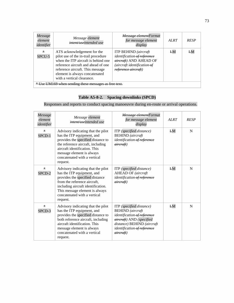
73
Message
element
identifier
Message element
intent/useintended use
Message elementFormat
for message element
display
ALRT RESP
*
SPCU-5
ATS acknowledgement for the
pilot use of the in-trail procedure
when the ITP aircraft is behind one
reference aircraft and ahead of one
reference aircraft. This message
element is always concatenated
with a vertical clearance.
ITP BEHIND (aircraft
identification of reference
aircraft) AND AHEAD OF
(aircraft identification of
reference aircraft)
LM LM
* Use UM169 when sending these messages as free text.
Table A5-8-2. Spacing downlinks (SPCD)
Responses and reports to conduct spacing manoeuvre during en-route or arrival operations.
Message
element
identifier
Message element
intent/useintended use
Message elementFormat
for message element
display
ALRT RESP
*
SPCD-1
Advisory indicating that the pilot
has the ITP equipment, and
provides the specified distance to
the reference aircraft, including
aircraft identification. This
message element is always
concatenated with a vertical
request.
ITP (specified distance)
BEHIND (aircraft
identification of reference
aircraft)
LM N
*
SPCD-2
Advisory indicating that the pilot
has the ITP equipment, and
provides the specified distance
from the reference aircraft,
including aircraft identification.
This message element is always
concatenated with a vertical
request.
ITP (specified distance)
AHEAD OF (aircraft
identification of reference
aircraft)
LM N
*
SPCD-3
Advisory indicating that the pilot
has the ITP equipment, and
provides the specified distance to
both reference aircraft, including
aircraft identification. This
message element is always
concatenated with a vertical
request.
ITP (specified distance)
BEHIND (aircraft
identification of reference
aircraft) AND (specified
distance) BEHIND (aircraft
identification of reference
aircraft)
LM N

74
Message
element
identifier
Message element
intent/useintended use
Message elementFormat
for message element
display
ALRT RESP
*
SPCD-4
Advisory indicating that the pilot
has the ITP equipment, and
provides the specified distance
from both reference aircraft,
including aircraft identification.
This message element is always
concatenated with a vertical
request.
ITP (specified distance)
AHEAD OF (aircraft
identification of reference
aircraft) AND (specified
distance) AHEAD OF
(aircraft identification of
reference aircraft)
LM N
*
SPCD-5
Advisory indicating that the pilot
has the ITP equipment, and
provides the specified distance to
one reference aircraft and the
specified distance from another
reference aircraft, including
aircraft identification. This
message element is always
concatenated with a vertical
request.
ITP (specified distance)
BEHIND (aircraft
identification of reference
aircraft) AND (specified
distance) AHEAD OF
(aircraft identification of
reference aircraft)
LM N
9. Emergency/urgency message elements
Table A5-9-1. Emergency/urgency uplinks (EMGU)
Instructions or annotations associated to instructions providing a high level of alert in the cockpit.
Message
element
identifier
Message element
intent/useintended use
Message elementFormat
for message element
display
ALRT RESP
131
EMGU-1
Instruction Request to report provide
the amount of fuel remaining (time)
and the number of persons on board.
REPORT REMAINING
FUEL ENDURANCE AND
PERSONS ON BOARD
MH Y
230
EMGU-2
Instruction to immediately comply
with the associated instruction is to
be complied with immediately to
avoid an imminent situation.
IMMEDIATELY H N
235
Notification of receipt of an
unlawful interference message.
ROGER 7500 H N
EMGU-3 Request to confirm an ADS-C
indicated emergency.
CONFIRM ADS-C
EMERGENCY
H A/N
199
(FreeText) H N
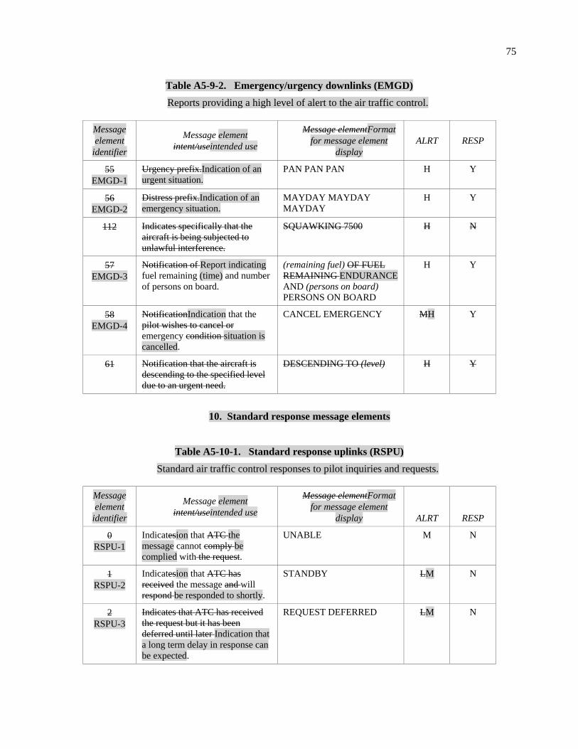
75
Table A5-9-2. Emergency/urgency downlinks (EMGD)
Reports providing a high level of alert to the air traffic control.
Message
element
identifier
Message element
intent/useintended use
Message elementFormat
for message element
display
ALRT RESP
55
EMGD-1
Urgency prefix.Indication of an
urgent situation.
PAN PAN PAN H Y
56
EMGD-2
Distress prefix.Indication of an
emergency situation.
MAYDAY MAYDAY
MAYDAY
H Y
112
Indicates specifically that the
aircraft is being subjected to
unlawful interference.
SQUAWKING 7500 H N
57
EMGD-3
Notification of Report indicating
fuel remaining (time) and number
of persons on board.
(remaining fuel) OF FUEL
REMAINING ENDURANCE
AND (persons on board)
PERSONS ON BOARD
H Y
58
EMGD-4
NotificationIndication that the
pilot wishes to cancel or
emergency condition situation is
cancelled.
CANCEL EMERGENCY MH Y
61 Notification that the aircraft is
descending to the specified level
due to an urgent need.
DESCENDING TO (level) H Y
10. Standard response message elements
Table A5-10-1. Standard response uplinks (RSPU)
Standard air traffic control responses to pilot inquiries and requests.
Message
element
identifier
Message element
intent/useintended use
Message elementFormat
for message element
display ALRT RESP
0
RSPU-1
Indicatesion that ATC the
message cannot comply be
complied with the request.
UNABLE M N
1
RSPU-2
Indicatesion that ATC has
received the message and will
respond be responded to shortly.
STANDBY LM N
2
RSPU-3
Indicates that ATC has received
the request but it has been
deferred until later Indication that
a long term delay in response can
be expected.
REQUEST DEFERRED LM N

76
Message
element
identifier
Message element
intent/useintended use
Message elementFormat
for message element
display ALRT RESP
3
RSPU-4
Indicatesion that ATC has
received and the message is
receivedunderstood the message.
ROGER LM N
4
RSPU-5
Yes Indication that ATC is
responding positively to the
message.
AFFIRM LM N
5
RSPU-6
No Indication that ATC is
responding negatively to the
message.
NEGATIVE LM N
211
RSPU-7
Indicatesion that ATC has
received the request and has
passed it been forwarded to the
next control authority unit.
REQUEST FORWARDED LM N
218
Indicates to the pilot that the
request has already been received
on the ground.
REQUEST ALREADY
RECEIVED
N N
143
RSPU-8
The requestRequest to confirm
the referenced request since the
initial request was not
understood. It The request should
be clarified and resubmitted.
CONFIRM REQUEST LM YN
Table A5-10-2. Standard response downlinks (RSPD)
Standard responses to air traffic control instructions and inquiries.
Message
element
identifier
Message element
intent/useintended use
Message elementFormat
for message element
display
ALRT RESP
0
RSPD-1
Indication that the instruction is
understood and will be complied
with.
WILCO M N
1
RSPD-2
Indication that the instruction
cannot be complied with.
UNABLE M N
2
RSPD-3
Wait for a reply Indication that the
message will be responded to
shortly.
STANDBY M N
3
RSPD-4
Indication that the message is
received and understood.
ROGER M N
4
RSPD-5
Yes. Indication of a positive
response to a message.
AFFIRM M N
5
RSPD-6
No. Indication of a negative
response to a message.
NEGATIVE M N
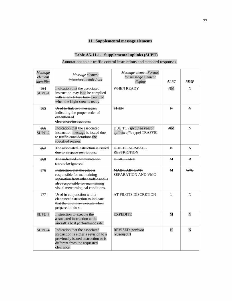
77
11. Supplemental message elements
Table A5-11-1. Supplemental uplinks (SUPU)
Annotations to air traffic control instructions and standard responses.
Message
element
identifier
Message element
intent/useintended use
Message elementFormat
for message element
display ALRT RESP
164
SUPU-1
Indication that the associated
instruction may is to be complied
with at any future time executed
when the flight crew is ready.
WHEN READY NM N
165 Used to link two messages,
indicating the proper order of
execution of
clearances/instructions.
THEN N N
166
SUPU-2
Indication that the associated
instruction message is issued due
to traffic considerations the
specified reason.
DUE TO (specified reason
uplinktraffic type) TRAFFIC
NM N
167 The associated instruction is issued
due to airspace restrictions.
DUE TO AIRSPACE
RESTRICTION
N N
168 The indicated communication
should be ignored.
DISREGARD M R
176 Instruction that the pilot is
responsible for maintaining
separation from other traffic and is
also responsible for maintaining
visual meteorological conditions.
MAINTAIN OWN
SEPARATION AND VMC
M W/U
177
Used in conjunction with a
clearance/instruction to indicate
that the pilot may execute when
prepared to do so.
AT PILOTS DISCRETION L N
SUPU-3 Instruction to execute the
associated instruction at the
aircraft’s best performance rate.
EXPEDITE M N
SUPU-4 Indication that the associated
instruction is either a revision to a
previously issued instruction or is
different from the requested
clearance.
REVISED (revision
reason[O])
H N

78
Table A5-11-2. Supplemental downlinks (SUPD)
Annotations to requests and standard responses.
Message
element
identifier
Message element
intent/useintended use
Message elementFormat
for message element
display
ALRT RESP
65
SUPD-1
Used to explain reasons Indication
for pilot’s that the associated
message is issued due to specified
reason.
DUE TO WEATHER
(specified reason downlink)
LN N
75
Used in conjunction with another
message to indicate that the pilot
wishes to execute request when the
pilot is prepared to do so.
AT PILOTS DISCRETION L N
66
Used to explain reasons for pilot’s
message.
DUE TO AIRCRAFT
PERFORMANCE
L N
74 States a desire by the pilot to
provide his/her own separation and
remain in VMC.
REQUEST TO MAINTAIN
OWN SEPARATION AND
VMC
L Y
101 Allows the pilot to indicate a desire
for termination of CPDLC service
with the current data authority.
REQUEST END OF
SERVICE
L Y
103
Allows the pilot to indicate that
he/she has cancelled IFR flight
plan.
CANCELLING IFR L Y
12. Free text message elements
Used when none of the standard message elements in the CPDLC message set in this appendix are appropriate for a specific intended use.
Table A5-12-1. Free text uplinks (TXTU)
Message
element
identifier
Message element
intent/useintended use
Message elementFormat
for message element
display ALRT RESP
169
TXTU-1
(free text) LM R
183
TXTU-2
(free text) M N
187
TXTU-3
(free text) N N
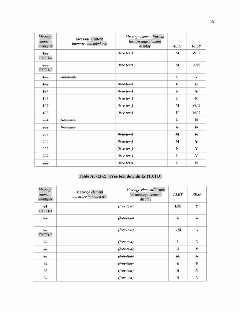
79
Message
element
identifier
Message element
intent/useintended use
Message elementFormat
for message element
display ALRT RESP
196
TXTU-4
(free text) M W/U
205
TXTU-5
(free text) M A/N
178 (reserved) L Y
170 (free text) H R
194 (free text) L Y
195 (free text) L R
197 (free text) M W/U
198 (free text) H W/U
201 Not used. L N
202 Not used. L N
203 (free text) M R
204 (free text) M Y
206 (free text) N Y
207 (free text) L Y
208 (free text) L N
Table A5-12-2. Free text downlinks (TXTD)
Message
element
identifier
Message element
intent/useintended use
Message elementFormat
for message element
display
ALRT RESP
91
TXTD-1
(free text) LM Y
97
(freeText) L N
98
TXTD-2
(freeText) NM N
67 (free text) L N
68 (free text) H Y
90 (free text) M N
92 (free text) L Y
93 (free text) H N
94 (free text) H N

80
Message
element
identifier
Message element
intent/useintended use
Message elementFormat
for message element
display
ALRT RESP
95 (free text) M N
96 (free text) L N
13. System management message elements
Table A5-13-1. System management uplinks (SYSU)
Messages dedicated to the management of the CPDLC communications (usually sent by the ground system).
Message
element
identifier
Message element
intent/useintended use
Message elementFormat
for message element
display
ALRT RESP
159
SYSU-1
A System-generated message
notifying that the ground system
has detected notification of an
error.
ERROR (error information) MN N
160
SYSU-2
Notification to the avionics that
the specified data authority is the
next data authority. If no data
authority is specified, this
indicates that any previously
specified next data authority is no
longer valid. System-generated
notification of the next data
authority or the cancellation
thereof.
NEXT DATA AUTHORITY
(facility designation[O])
NM N
161 Notification to the avionics that
the data link connection with the
current data authority is being
terminated.
END SERVICE N N
162
SYSU-3
System-generated Nnotification
that the ground system does not
support this received message is
not supported.
MESSAGE NOT
SUPPORTED BY THIS
ATSC UNIT
LM N
163 Notification to the pilot of an
ATSU identifier.
(facility designation) N N

81
Message
element
identifier
Message element
intent/useintended use
Message elementFormat
for message element
display
ALRT RESP
227
SYSU-4
Confirmation to the aircraft
system System-generated
notification that the ground
system has received the message
to which the logical
acknowledgement refers and
found it is acceptable for display
to the responsible person.
LOGICAL
ACKNOWLEDGEMENT
MN N
233
SYSU-5
Notification to A
system-generated message
indicating that messages sent
requiring a requests for logical
acknowledgement will
acknowledgements are not be
accepted by this ground system
permitted.
USE OF LOGICAL
ACKNOWLEDGEMENT
PROHIBITED
M N
234 Notification that the ground
system does not have a flight plan
for that aircraft.
FLIGHT PLAN NOT HELD L N
SYSU-6 Advisory providing the maximum
one-way uplink message
transmission delay.
LATENCY TIME VALUE
(latency value)
N N
SYSU-7 Indication that the received
message has a latency greater
than the requirement.
MESSAGE RECEIVED
TOO LATE, RESEND
MESSAGE OR CONTACT
BY VOICE
M N
Table A5-13-2. System management downlinks (SYSD)
Messages dedicated to the management of the CPDLC communications (usually sent by aircraft system).
Message
element
identifier
Message element
intent/useintended use
Message elementFormat
for message element
display
ALRT RESP
62
SYSD-1
A System-generated message that
the avionics has detected
notification of an error.
ERROR (error information) LN N
100
SYSD-2
Confirmation to the ground system
System-generated notification that
the aircraft system has received the
message to which the logical
acknowledgement refers and found
it is acceptable for display to the
responsible person.
LOGICAL
ACKNOWLEDGEMENT
MN N
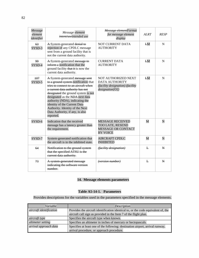
82
Message
element
identifier
Message element
intent/useintended use
Message elementFormat
for message element
display
ALRT RESP
63
SYSD-3
A System-generated denial to
rejection of any CPDLC message
sent from a ground facility that is
not the current data authority.
NOT CURRENT DATA
AUTHORITY
LM N
99
SYSD-4
A System-generated message to
inform a notification that the
ground facility that it is now the
current data authority.
CURRENT DATA
AUTHORITY
LM N
107
SYSD-5
A System-generated message sent
to a ground system notification that
tries to connect to an aircraft when
a current data authority has not
designated the ground system is not
designated as the NDA next data
authority (NDA), indicating the
identity of the Current Data
Authority. Identity of the Next
Data Authority, if any, is also
reported.
NOT AUTHORIZED NEXT
DATA AUTHORITY
(facility designation) (facility
designation[O])
LM N
SYSD-6 Indication that the received
message has a latency greater than
the requirement.
MESSAGE RECEIVED
TOO LATE, RESEND
MESSAGE OR CONTACT
BY VOICE
M N
SYSD-7 System-generated notification that
the aircraft is in the inhibited state.
AIRCRAFT CPDLC
INHIBITED
M N
64 Notification to the ground system
that the specified ATSU is the
current data authority.
(facility designation) L N
73 A system-generated message
indicating the software version
number.
(version number) L N
14. Message elements parameters
Table A5-14-1. Parameters
Provides descriptions for the variables used in the parameters specified in the message elements.
Variable Description
aircraft identification Provides the aircraft identification identical to, or the code equivalent of, the
aircraft call sign as provided in the Item 7 of the flight plan.
aircraft type Specifies the aircraft type when known.
altimeter setting Specifies an altimeter in inches of mercury or hectopascals.
arrival approach data Specifies at least one of the following: destination airport, arrival runway,
arrival procedure, or approach procedure.

83
Variable Description
ATIS code Specifies the current ATIS code.
ATS route designator Specifies the 2-7 character name of the route.
along track waypoint Specifies point in the route specified as relative distance for another
waypoint on the route. May include speed and level constraints at this point.
clearance limit Specifies the farthest cleared point as a position.
clearance name Specifies a 2-14 character name of a clearance, usually specifying the name
of an unpublished procedure or route.
clearance type Specifies the type of clearance as: approach, departure, further, startup,
pushback, taxi, or oceanic.
degrees Specifies direction in terms of degrees as either degrees from magnetic north
or degrees from true north.
departure clearance Specifies the required departure clearance information as one or more of the
following:
departure airport;
departure runway;
cleared to position;
departure route data specified as either;
o the route is as filed; or
o a SID and optionally that the rest of the route after the SID is as
filed (i.e. then as filed).
departure level, and any constraint on the level (duration or until
position);
expected level and any constraint on the level (duration or until
position);
departure speed and any constraint on the speed (duration or until
position);
departure heading in degrees;
indication when no delay is expected;
target start-up approval time;
arrival and/or approach procedures including any special instructions;
SSR code;
ATIS code; and/or
departure frequency.
departure data Specifies the departure data as at least one of the following: departure
airport, departure runway, or departure procedure.
deviation type Specifies the deviation type as a lateral position, level or speed.
direction Specifies direction as:
left, right, or either side;
north, south, east, or west; or
northeast, northwest, southeast, or southwest.
SSR code Specifies the SSR code as 4 octal digits.
specified reason downlink Specifies the reason for the associated message as weather or aircraft
performance.
specified reason uplink Specifies the reason for the associated message as: opposite direction traffic,
same direction traffic, converging traffic, crossing traffic, or diverging
traffic, airspace restriction, invalid oceanic entry point, no flight plan held,
oceanic clearance request received too late.
error information Specifies reason for error as: unrecognized message reference number,
insufficient resources, checksum failure, or undefined.

84
Variable Description
ETP time Specifies the estimated time (hours and minutes) of passing opposite
direction traffic.
facility designation Specifies the ICAO location indicator for a facility.
facility function Specifies the function of the facility as: centre, approach, tower, final, ground
control, clearance delivery, departure, control, radio, apron, information,
ramp, flight watch, AOC/company, de-icing, or flight service.
free text Provides additional information in a non-structured format.
frequency Specifies the frequency as an HF, VHF, or UHF frequency, or as a
SATVOICE number.
hold at waypoint Specifies a holding instruction providing the position of the holding as:
position, and additionally any or all of the following:
holding speed low, waypoint level constraint, holding speed high, a left or
right holding, degrees, time a further clearance is expected, and leg type.
latency value Provides the CPDLC message latency value in seconds.
lateral deviation Specifies the lateral deviation as the permitted distance left, right, or either
side from the cleared route in nautical miles or kilometres.
latitude longitude Specifies the latitude and longitude in degrees, minutes, tenths of minutes
and direction (north, south, east or west).
leg type Specifies a holding leg as distance (tenths of nautical miles or tenths of
kilometres) or time (tenths of minutes).
level Specifies a level as a single or block level in feet, metres, or flight levels.
level single Specifies a single level in feet, metres, or flight levels.
named instruction Specifies a named instruction as either a clearance name or a procedure
name.
number of degrees Provides the number of degrees.
number of minutes Provides the number of minutes (time).
persons on board Provides the number of persons on board or indicates that the number is
unknown.
place bearing distance Specifies a place bearing and a distance in nautical miles or kilometres.
place bearing Specifies a published identifier and degrees.
position Specifies a position as a:
published identifier;
latitude longitude; or
place bearing distance.
Position report Provides information similar to a voice position report as defined in 4.11.2.
procedure name Specifies a procedure name by specifying a procedure type (departure,
arrival, or approach) and identifier (1-20 characters), and when applicable:
the runway;
any required procedure transition; and/or
any required additional information about the procedure.
published identifier Specifies the published identifier name (1-5 characters) and associated
latitude and longitude (degrees, minutes, seconds).
relay text Specifies the information to be relayed to the specified aircraft as free text.
relayed text response Specifies information relayed from the specified aircraft as free text.
remaining fuel Specifies remaining fuel as time in seconds.
revision reason Specifies the reason(s) for the clearance revision as any or all of the
following: a level change, a speed change, a route change at a specified
position, a route change at multiple waypoints, an entry point change, a
clearance limit change, a named instruction change, and/or a ground location
change.

85
Variable Description
en-route data Specifies the cleared route of flight for up to 128 waypoints with positional
information (route information), including for each waypoint as required,
level constraint, speed constraint, required time of arrival, holding instruction
and fly-by or flyover information (route information additional). A
clearance limit may be included. A locally defined named instruction may
also be included.
route information additional Specifies any or all of the following:
1 to 8 along track waypoint;
1 to 8 hold at waypoint;
1 to 32 waypoint speed level; and
1 to 32 required time arrival.
route information Specifies route information as one of:
published identifier;
latitude longitude;
place bearing distance; or
ATS route designator.
required time arrival For the specified position, provides the required time of arrival (hours,
minutes (seconds (optional)), optionally any tolerance around the required
time of arrival, and indicates the required time of arrival as at, before, or after
the specified time.
runway Specifies a runway by direction and configuration (left, right, centre, or
none).
specified deviation Specifies the deviation from the route as a specified distance or number of
degrees.
specified distance Specifies distance in nautical miles or kilometres.
speed Specifies speed in English or metric units as indicated, true, ground, or Mach
speed.
speed types Specifies the speed as a minimum or maximum and 1 to 2 speed type(s),
where the speed type indicates speed as: indicated, true, ground, Mach,
approach, cruise, or present.
time Specifies time in hours and minutes.
traffic description Specifies a description of traffic significant to a flight by providing any or all
of the following information: the aircraft flight identification, the aircraft
type, the current flight level of the aircraft, the location relative to the given
aircraft as the distance (if known) above or below, and indicates when known
that the traffic is, opposite direction, same direction, converging, crossing, or
diverging from the given aircraft.
traffic location Specifies the location for opposite direction traffic indicating if the traffic is
above or below the given aircraft, and when known, provides the vertical
distance in feet or metres.
traffic visibility Indicates the traffic visibility as: “sighted and passed”, “sighted”, or “not
sighted”.
unit name Specifies the unit name by providing any or all of the following: facility
name, facility designation, or facility function as appropriate.
vertical rate Specifies the vertical rate as feet/minute or metres/minute.
waypoint speed level Specifies the speed and level constraints on the specified position.
— END —

AMENDMENT No. 7-B
TO THE
PROCEDURES
FOR
AIR NAVIGATION SERVICES
AIR TRAFFIC MANAGEMENT
(Doc 4444)
INTERIM EDITION
The text of Amendment No. 7-B to the PANS-ATM (Doc 4444) was approved
by the President of the Council of ICAO on behalf of the Council on
6 June 2016 for applicability on 5 November 2020. This interim edition is
distributed to facilitate implementation of the amendment by States.
Replacement pages incorporating Amendment No. 7-B are expected to be
distributed in October 2016. (State letter AN 13/2.1-16/54 refers.)
June 2016
INTERNATIONAL CIVIL AVIATION ORGANIZATION

2
NOTES ON THE EDITORIAL PRESENTATION
OF THE AMENDMENT 7-B TO THE PANS-ATM
The text of the amendment is arranged to show deleted text with a line through it and new text
highlighted with grey shading, as shown below:
1. Text to be deleted is shown with a line through it. text to be deleted
2. New text to be inserted is highlighted with grey shading. new text to be inserted
3. Text to be deleted is shown with a line through it
followed by the replacement text which is highlighted
with grey shading.
new text to replace existing text

3
TEXT OF AMENDMENT 7-B TO THE
PROCEDURES FOR AIR NAVIGATION SERVICES
AIR TRAFFIC MANAGEMENT
Chapter 1
DEFINITIONS
. . .
Situation display. An electronic display depicting the position and movement of aircraft and other
information as required.
Slush. Water-saturated snow which with a heel-and-toe slap-down motion against the ground will be
displaced with a splatter; specific gravity: 0.5 up to 0.8.
Note.— Combinations of ice, snow and/or standing water may, especially when rain, rain and snow, or
snow is falling, produce substances with specific gravities in excess of 0.8. These substances, due to their
high water/ice content, will have a transparent rather than a cloudy appearance and, at the higher specific
gravities, will be readily distinguishable from slush.
Snow (on the ground).
a) Dry snow. Snow which can be blown if loose or, if compacted by hand, will fall apart upon release;
specific gravity: up to but not including 0.35.
b) Wet snow. Snow which, if compacted by hand, will stick together and tend to or form a snowball;
specific gravity: 0.35 up to but not including 0.5.
c) Compacted snow. Snow which has been compressed into a solid mass that resists further
compression and will hold together or break up into lumps if picked up; specific gravity: 0.5 and
over.
Special VFR flight. A VFR flight cleared by air traffic control to operate within a control zone in
meteorological conditions below VMC.
. . .
4.12 REPORTING OF OPERATIONAL AND
METEOROLOGICAL INFORMATION
. . .
4.12.3 Contents of special air-reports
4.12.3.1 Special air-reports shall be made by all aircraft whenever the following conditions are
encountered or observed:

4
a) moderate or severe turbulence; or
b) moderate or severe icing; or
c) severe mountain wave; or
d) thunderstorms, without hail that are obscured, embedded, widespread or in squall lines; or
e) thunderstorms, with hail that are obscured, embedded, widespread or in squall lines; or
f) heavy duststorm or heavy sandstorm; or
g) volcanic ash cloud; or
h) pre-eruption volcanic activity or a volcanic eruption. ; or
i) runway braking action encountered is not as good as reported.
Note.— Pre-eruption volcanic activity in this context means unusual and/or increasing volcanic
activity which could presage a volcanic eruption.
Editorial Note.— Renumber subsequent bullets accordingly.
. . .
4.12.6 Forwarding of meteorological information
. . .
4.12.6.3 When receiving special air-reports by voice communications, air traffic services units shall
forward them without delay to their associated meteorological watch offices, with the exception of
conditions applying to runway braking action encountered.
4.12.7 Forwarding of braking action information
When receiving special air-reports by voice communications concerning braking action encountered that is
not as good as that reported, air traffic service units shall forward them without delay to the appropriate
aerodrome operator.
. . .

5
Chapter 7
PROCEDURES FOR AERODROME CONTROL SERVICE
. . .
7.5 ESSENTIAL INFORMATION ON AERODROME CONDITIONS
. . .
7.5.2 Essential information on aerodrome conditions shall include information relating to
the following:
a) construction or maintenance work on, or immediately adjacent to the movement area;
b) rough or broken surfaces on a runway, a taxiway or an apron, whether marked or not;
c) water, snow, slush or , ice or frost on a runway, a taxiway or an apron;
d) water on a runway, a taxiway or an apron anti-icing or de-icing liquid chemicals or other
contaminant on a runway, taxiway or apron;
e) snow banks or drifts adjacent to a runway, a taxiway or an apron;
f) other temporary hazards, including parked aircraft and birds on the ground or in the air;
g) failure or irregular operation of part or all of the aerodrome lighting system;
h) any other pertinent information.
Note.— Up-to-date information on the conditions on aprons may not always be available to the
aerodrome control tower. The responsibility of the aerodrome control tower in relation to aprons is, with
respect to the provisions of 7.5.1 and 7.5.2, limited to the transmission to aircraft of the information which is
provided to it by the authority responsible for the aprons.
. . .
Chapter 11
AIR TRAFFIC SERVICES MESSAGES
. . .
11.4.3.4 MESSAGES CONTAINING INFORMATION ON AERODROME CONDITIONS
Note.— Provisions regarding the issuance of information on aerodrome conditions are contained in
Chapter 7, 7.5.
11.4.3.4.1 Whenever information is provided on aerodrome conditions, this shall be done in a
clear and concise manner so as to facilitate appreciation by the pilot of the situation described. It shall be
issued whenever deemed necessary by the controller on duty in the interest of safety, or when requested by

6
an aircraft. If the information is provided on the initiative of the controller, it shall be transmitted to each
aircraft concerned in sufficient time to enable the pilot to make proper use of the information.
11.4.3.4.2 Information that water is present on a runway shall be transmitted to each aircraft
concerned, on the initiative of the controller, using the following terms Whenever information is provided
concerning runway surface conditions that may adversely affect aircraft braking action, the following terms
shall be used, as necessary:
DAMP — the surface shows a change of colour due to moisture.
WET — the surface is soaked but there is no standing water.
STANDING WATER — for aeroplane performance purposes, a runway where more than 25 per cent of the
runway surface area (whether in isolated areas or not) within the required length and width being used is
covered by water more than 3 mm deep.
COMPACTED SNOW
DRY
DRY SNOW
DRY SNOW ON TOP OF COMPACTED SNOW.
DRY SNOW ON TOP OF ICE.
FROST
ICE
SLUSH
STANDING WATER
WATER ON TOP OF COMPACTED SNOW
WET
WET ICE
WET SNOW
WET SNOW ON TOP OF COMPACTED SNOW.
WET SNOW ON TOP OF ICE.
11.4.3.4.3 Appropriate ATS units shall have available for transmission to aircraft, upon request,
the Runway Condition Report information. This shall be passed to aircraft in the order of the direction of
landing or take-off.

7
. . .
Chapter 12
PHRASEOLOGIES
. . .
12.3 ATC PHRASEOLOGIES
12.3.1 General
. . .
12.3.1.11 AERODROME INFORMATION
Note 1.— See 11.4.3.4.3 for requirements for
passing RCR to pilots.
Note 2.— This information is provided for
runway thirds or the full runway, as
applicable.
a) [(location)] RUNWAY SURFACE CONDITION
RUNWAY (number) (condition)
a) [(location)] RUNWAY (number) SURFACE
CONDITION [CODE (three digit number)]
followed as necessary by:
1. ISSUED AT (date and time UTC);
2. DRY, or WET ICE, or WATER ON TOP OF
COMPACTED SNOW, or DRY SNOW, or
DRY SNOW ON TOP OF ICE, or WET
SNOW ON TOP OF ICE, or ICE, or SLUSH,
or STANDING WATER, or COMPACTED
SNOW, or WET SNOW, or DRY SNOW ON
TOP OF COMPACTED SNOW, or WET
SNOW ON TOP OF COMPACTED SNOW,
or WET, or FROST;
3. DEPTH ((depth of deposit) MILLIMETRES or
NOT REPORTED);
4. COVERAGE ((number) PER CENT or NOT
REPORTED);
5. ESTIMATED SURFACE FRICTION (GOOD,
or GOOD TO MEDIUM, or MEDIUM, or
MEDIUM TO POOR, or POOR, or LESS
THAN POOR);
6. AVAILABLE WIDTH (number) METRES;
7. LENGTH REDUCED TO (number) METRES;
8. DRIFTING SNOW;
9. LOOSE SAND;
10. CHEMICALLY TREATED;
11. SNOWBANK (number) METRES [LEFT, or

8
RIGHT or LEFT AND RIGHT] [OF or
FROM] CENTRELINE;
12. TAXIWAY (identification of taxiway)
SNOWBANK (number) METRES [LEFT, or
RIGHT or LEFT AND RIGHT] [OF or
FROM] CENTRELINE;
13. ADJACENT SNOWBANKS;
14. TAXIWAY (identification of taxiway) POOR;
15. APRON (identification of apron) POOR;
16. Plain language remarks
b) . . .
e) CAUTION (specify reasons) RIGHT (or LEFT),
(or BOTH SIDES) OF RUNWAY [(number)];
. . .
g) RUNWAY REPORT AT (observation time)
RUNWAY (number) (type of precipitant) UP TO
(depth of deposit) MILLIMETRES. ESTIMATED
SURFACE FRICTION GOOD (or MEDIUM TO
GOOD, or MEDIUM, or MEDIUM TO POOR, or
POOR;
h g) BRAKING ACTION REPORTED BY (aircraft
type) AT (time) GOOD (or MEDIUM to GOOD
TO MEDIUM, or MEDIUM, or MEDIUM to TO
POOR, or POOR);
i h) RUNWAY (or TAXIWAY) (number identification
of taxiway) WET [or STANDING WATER, or
SNOW REMOVED (length and width as
applicable), or CHEMICALLY TREATED, or
COVERED WITH PATCHES OF DRY SNOW (or
WET SNOW, or COMPACTED SNOW, or
SLUSH, or FROZEN SLUSH, or ICE, or WET
ICE, or ICE UNDERNEATH, or ICE AND
SNOW, or SNOWDRIFTS, or FROZEN RUTS
AND RIDGES or LOOSE SAND)];
j i) TOWER OBSERVES (weather information);
k j) PILOT REPORTS (weather information).
. . . . . . . . .

9
Appendix 1
INSTRUCTIONS FOR AIR-REPORTING
BY VOICE COMMUNICATIONS
. . .
1. Reporting instructions
MODEL AIREP SPECIAL
ITEM PARAMETER TRANSMIT IN TELEPHONY as appropriate
Sec
tion
3
. . . 9
Phenomenon encountered or observed, prompting a special air-report: • Moderate turbulence • Severe turbulence • Moderate icing • Severe icing • Severe mountainwave • Thunderstorms without hail • Thunderstorms with hail • Heavy dust/sandstorm • Volcanic ash cloud • Pre-eruption volcanic
activity or volcanic eruption
Runway braking action
Good Good to Medium Medium Medium to Poor Poor Less than Poor
TURBULENCE MODERATE TURBULENCE SEVERE ICING MODERATE ICING SEVERE MOUNTAINWAVE SEVERE THUNDERSTORMS THUNDERSTORMS WITH HAIL DUSTSTORM or SANDSTORM HEAVY VOLCANIC ASH CLOUD PRE-ERUPTION VOLCANIC ACTIVITY or VOLCANIC ERUPTION
GOOD GOOD TO MEDIUM MEDIUM MEDIUM TO POOR POOR LESS THAN POOR
. . .
Section 3
Item 9 — PHENOMENON PROMPTING A SPECIAL AIR-REPORT. Report one of the following
phenomena encountered or observed:
. . .
• volcanic ash cloud as “VOLCANIC ASH CLOUD”
• pre-eruption volcanic activity or a volcanic eruption as “PRE-ERUPTION VOLCANIC
ACTIVITY or VOLCANIC ERUPTION”
The following specification applies:

10
Pre-eruption volcanic activity in this context means unusual and/or increasing volcanic activity
which could presage a volcanic eruption.
Note.— In case of volcanic ash cloud, pre-eruption volcanic activity or volcanic eruption, in
accordance with Chapter 4, 4.12.3, a post-flight report shall also be made on the special air-report
of volcanic activity form (Model VAR).
• Good braking action as “BRAKING ACTION GOOD”
Good to medium braking action as “BRAKING ACTION GOOD TO MEDIUM”
Medium braking action as “BRAKING ACTION MEDIUM”
Medium to poor braking action as “BRAKING ACTION MEDIUM TO POOR”
Poor braking action as “BRAKING ACTION POOR”
Less than poor braking action as “BRAKING ACTION LESS THAN POOR”
The following specifications apply:
Good — Braking deceleration is normal for the wheel braking effort applied and directional
control is normal.
Good to medium — Braking deceleration or directional control is between Good and Medium.
Medium — Braking deceleration is noticeably reduced for the wheel braking effort applied or
directional control is noticeably reduced.
Medium to poor — Braking deceleration or directional control is between Medium and Poor.
Poor — Braking deceleration is significantly reduced for the wheel braking effort applied or
directional control is significantly reduced.
Less than poor — Braking deceleration is minimal to non-existent for the wheel braking effort
applied or directional control is uncertain.
2.2 Information recorded on the volcanic activity reporting form (Model VAR) is not for
transmission by RTF but, on arrival at an aerodrome, is to be delivered without delay by the operator or a
flight crew member to the aerodrome meteorological office. If such an office is not easily accessible, the
completed form shall be delivered in accordance with local arrangements made between the meteorological
and ATS authorities and the operator.
. . .
— END —