submarine canyon morphologies and evolution in...
TRANSCRIPT

Contents lists available at ScienceDirect
Marine Geology
journal homepage: www.elsevier.com/locate/margo
Submarine canyon morphologies and evolution in modern carbonatesettings: The northern slope of Little Bahama Bank, Bahamas
Elsa Tournadoura,⁎,1, Thierry Muldera, Jean Borgomanob, Hervé Gilleta, Ludivine Chabauda,Emmanuelle Ducassoua, Vincent Hanquieza, Samuel Etiennec
a Université de Bordeaux, UMR 5805 EPOC, Site de Talence Bâtiment B18N, Allée Geoffroy Saint-Hilaire, CS 50023, 33615 Pessac, Franceb Université d'Aix-Marseille, CEREGE/UMR6635, case 67, 3, Place Victor Hugo, 13331 Marseille, Francec ADECAL Technopole, C/O Geological Survey of New Caledonia, DIMENC, 1 ter rue Unger, Vallée du Tir, B.P. 465, 98845 Nouméa, New Caledonia
A B S T R A C T
The recent high-quality multibeam echosounder swath bathymetry data and very high-resolution seismic pro-files collected along the northern slope of Little Bahama Bank (LBB, Bahamas) constitute a unique dataset thatcan be used to investigate submarine canyon morphologies in modern carbonate settings. This region representsone of the few examples of submarine canyons that have developed in a purely carbonate system around theworld. Our study reveals that there are 18 submarine canyons within the survey area that incise the slopebetween water depths of 450 m and 1000 m. Morpho-sedimentary analyses allow us to characterise their geo-metry and spatial distribution and to interpret their formation and control parameters. Among these canyons wedistinguish four types: the amphitheatre-shaped canyons (1), canyons with up-dip linear incisions (2), canyonswith internal recent depositional geometries, including levees and aggrading terraces on the side of their talweg(3) and canyons that are partially to completely filled (4). Based on these new morphological and geometricalclassifications, the distributions of canyon morphologies and the integration of the full dataset, we propose amodel for the formation and evolution of carbonate canyons. The latter emphasises that canyon initiation issolely the result of slope failures, which subsequently evolve into proper canyons through two successive phasesof retrogressive erosion processes that are controlled by a downslope submarine cementation gradient. The firstphase of retrogressive erosion produces widened canyon shapes at water depths of up to 600 m, whereas thesecond phase forms up dip-propagating linear incisions at water depths of up to 450 m. These linear incisions,which are located 5 to 10 km away from the platform edge, favour the funnelling of sediment fluxes originatingfrom the platform. Subsequently or contemporaneously with this retrogressive erosion, muddy gravity flows areresponsible for canyon-fills and the formation of levees and aggrading terraces, which will eventually lead to thecomplete infill of the canyons, marking the end of an “erosion-fill” cycle. On a larger scale, the persistence ofsuch canyons on the slope of LBB is of particular interest, as these are considered to be an exception along thepresent-day accretionary Bahamian slopes. Although similar canyons have been identified along the westernslope of Great Bahama Bank (GBB), today these are totally buried, unlike those of LBB. We therefore suggest thatthe persistence of LBB canyons may be the result of relatively low sedimentation rates linked with the windwardorientation of the platform. This low sedimentation rate has prevented the burial of these canyons since thePliocene.
1. Introduction
Submarine canyons, which were originally discovered by Shepard(1936), are deep steep incisions that cut the continental shelf and slopeand constitute the main conduit for the transport of sediment from thecontinent to the deep sea (Shepard et al., 1969; Normark and Carlson,2003). Their initiation and entrenchment are generally closely related
to erosional processes, and they may be persistent structures over longperiods of time. Therefore, submarine canyons play a major role in notonly sediment transfer from “source” to “sink” but also in dictating thegeneral morphology and evolution of continental margins.
Three different processes have been proposed to explain the originof submarine canyons: (1) precursory subaerial erosion during sig-nificant drops in relative sea level followed by submarine erosion
http://dx.doi.org/10.1016/j.margeo.2017.07.014Received 13 December 2016; Received in revised form 10 July 2017; Accepted 17 July 2017
⁎ Corresponding author.
1 Present address: ADECAL Technopole, C/O Geological Survey of New Caledonia, DIMENC, 1 ter rue Unger, Vallée du Tir, B.P. 465, 98845 Nouméa, New Caledonia.E-mail address: [email protected] (E. Tournadour).
Marine Geology 391 (2017) 76–97
Available online 21 July 20170025-3227/ © 2017 Elsevier B.V. All rights reserved.
MARK

(Shepard, 1981); (2) retrogressive submarine erosion linked to intra-slope destabilisation and/or downslope eroding gravity flows (Shepard,1981; Pratson et al., 1994; Pratson and Coakley, 1996); and (3)downslope continuous submarine erosion related to recurring gravityprocesses, such as hyperpycnal currents generated at the mouths oflarge rivers (Mulder et al., 2003) or other coastal and shelf hydro-dynamic processes (e.g., coastal drifts or shelf currents) (Lewis andBarnes, 1999; Canals et al., 2006; Mazières et al., 2014).
In isolated carbonate platform settings, the absence of a terrigenousfluvial system generally rules out the hypothesis of fluvial erosionduring major emersion periods as well as the involvement of hy-perpycnal currents associated with major floods in the origin of sub-marine canyons. This raises the following questions: what are the maincontrolling factors in the formation and evolution of submarine canyonsin carbonate settings? Are they only the result of intra-slope destabili-sation events and retrogressive erosion or is there any relationshipbetween the supply and transfer of sediment from the platform and theexpansion of the canyon?
These critical questions remain unanswered largely because most ofthe numerous studies of submarine canyons have focused on canyons insiliciclastic depositional environments (see Harris and Whiteway, 2011and Huneke and Mulder, 2010), whereas modern submarine canyons incarbonate settings remain relatively poorly documented. However,several studies of particular note have focused on Australian con-tinental margins (e.g., Exon et al., 2005; Mitchell et al., 2007). For
example, the canyons of the Albany submarine canyon complex (off-shore Southwest Australia) appear to have been inherited from silici-clastic fluvial systems that formed prior to the Middle Eocene ratherthan from the present-day carbonate sedimentation that fills thesecanyons (Exon et al., 2005). Other examples have been described in themixed carbonate-siliciclastic systems of the northeastern Australianmargin (Webster et al., 2012; Puga-Bernabéu et al., 2011, 2013, 2014).In these cases, canyon formation does not imply an initiation that iscontrolled by fluvial input but is instead primarily linked with intra-slope destabilisations followed by retrogressive erosion (Puga-Bernabéuet al., 2011). Additionally, along the slopes of the isolated Bahamianplatforms, small fossil buried canyons and modern gully systems havealso been described on the western slope of Great Bahama Bank (GBB)(Anselmetti et al., 2000; Mulder et al., 2012a; Betzler et al., 2014;Principaud et al., 2016) and the southern slope of Little Bahama Bank(LBB) (Burns and Neumann, 1987). Nevertheless, these architecturalelements have been characterised using only 2D seismic lines, whereasthe canyons of the northern slope of LBB have been characterised usingboth 2D seismic lines and a high-resolution multibeam echosounder,which can yield more detailed descriptions of canyon geometries.
In this way, the analysis of the submarine canyons on the northernslope of LBB constitute a relevant case study that can be used to un-derstand the formation of canyons in purely carbonate settings. Thesefeatures, which were originally identified as simple gullies or linearcanyons by previous workers (Van Buren and Mullins, 1983; Mullins
Fig. 1. Satellite image of the Bahamas archipelago and location of Leg 2 (this study, Figs. 2A, 3A) and Leg 1 of the Carambar cruise (Nov 2010, RV Le Suroit). The Antilles and Floridacurrents are the main oceanic currents (yellow arrows) along the Bahamas. Note that the northern slope of Little Bahama Bank marks a regional boundary between the Bahamasarchipelago and the Blake Plateau. LBB: Little Bahama Bank; GBB: Great Bahama Bank; T.O.T.O: Tongue Of The Ocean. (For interpretation of the references to colour in this figure legend,the reader is referred to the web version of this article.)
E. Tournadour et al. Marine Geology 391 (2017) 76–97
77

et al., 1984; Harwood and Towers, 1988) are actually characterised bycomplex geometries with widened parts or amphitheatre shapes thatspread upward into linear incisions. Mulder et al. (2012b) describedthese architectural elements and showed that canyons open on shortchannels and depositional fan-shaped lobes. These small turbidite sys-tems show some similarities to siliciclastic systems. The present con-tribution focuses mainly on these submarine canyons; its main objectiveis to present a detailed morphological and sedimentary characterisationof these canyons using surface data combined with very high-resolutionseismic profiles to better understand their formation and evolution, aswell as their relationships to sedimentary transfer originating from theLBB platform. This detailed analysis eventually allows us to propose anew canyon classification based on their morphology, infill style, andarchitecture, as well as to discuss their stage of formation and theirspatial distribution along the northern slope of LBB in relation to theirmain control parameters.
2. General settings of the northern slope of LBB
LBB is bordered to the south by the NW Providence Channel, to thewest by the Straits of Florida, to the north by the Blake Plateau and tothe east by the Blake-Bahama Escarpment, which marks the boundarybetween the Bahamas archipelago and the Blake-Bahama Basin (Fig. 1).The LBB platform is the second-largest isolated platform in the Bahamas(Fig. 1); it is 50 to 100 km wide and over 250 km long and exhibits anESE-WNW orientation. Most of LBB is submerged; the Grand Bahamaand Abaco islands represent only 15% of the total surface of the bank.The remaining 85% of the bank surface corresponds to a lagoon with awater depth ranging from 1 to 10 m. The northern slope of LBB is es-sentially defined as an open ocean windward margin; it also includes anextended leeward margin on its northwest extremity that has progradednorthward (Mullins and Neumann, 1979). This northward progradationis the result of the growth of the LBB drift (Tournadour et al., 2015;Chabaud et al., 2016) under the combined action of the Florida andAntilles currents (Fig. 1) and represents a good example of the criticalrole that oceanic circulation plays in the shaping of Bahamian slopesand its associated deep-water sedimentation (Tournadour et al., 2015).The deepest part of the study area is bathed by the Labrador Sea Water,which represents the upper part of the Western Boundary Undercurrent(WBUC) (Evans et al., 2007).
2.1. Tectonic events and slope evolution
The northern slope of LBB is situated at a regional structuralboundary between the Bahamas and the Blake Plateau. Its structure isclosely related to the Cuban orogenesis and more particularly to theopening of the Great Abaco Canyon (Fig. 1), whose origin has beenlinked to the vertical motion that occurred along the Great AbacoFracture Zone from the Upper Cretaceous to the Eocene (Van Buren andMullins, 1983; Mullins et al., 1982). During the Paleogene, the GreatAbaco Canyon was partially filled by pelagic sediments derived from adeep oceanic environment (Austin et al., 1988), thus leading to a morerestricted canyon. Following this, a regional event called the “AbacoEvent” led to the formation of wide destabilisations across all Bahamianslopes, together with the export of large volumes of sediment towardsthe Blake-Bahamas Basin from the Oligocene to the Middle Miocene(Benson et al., 1975; Bliefnick et al., 1983; Austin et al., 1988). Fol-lowing this regional event, the northern slope of LBB began progradingnorthward; this progradation has continued until the present day (SEQ-D, Fig. 2B). ODP well 630 shows that the upper slope is mainly com-posed of periplatform ooze and minor chalk. During the Late Miocene,the deposition of periplatform ooze alternated with that of packstone-grainstone turbidites that formed slope apron deposits. Since the Plio-cene, turbidites have constituted only 10% of the slope deposits (Austinet al., 1986) (SEQ-D, Fig. 2B). ODP well 627 is located on the lowerslope and records Pliocene and Quaternary deposits that are mainly
composed of periplatform oozes, with thin floatstones and minorgraded packstones that have been interpreted as turbidites. The latterunits are dominated by aggregates of planktonic foraminifers, containonly minor shallow-water debris and have been interpreted to be slope-derived deposits (Austin et al., 1986). The upper slope is characterisedby numerous instability features, such as submarine slides, gullies andcanyons (Van Buren and Mullins, 1983; Harwood and Towers, 1988;Mulder et al., 2012b; Tournadour et al., 2015) (Fig. 2). The compositeseismic profile 44–57 shows that numerous incisions affected thenorthern slope of LBB during the Neogene (Fig. 2C). The 18 submarinecanyons clearly imaged on the seafloor (Fig. 2A and Fig. 3A) incisedPliocene deposits (Fig. 2C) and consequently formed after the LateMiocene.
2.2. Platform environments
The Bahamas archipelago consists of a mosaic of isolated tropicalplatforms that produce both skeletal and nonskeletal carbonate sedi-ments (Enos, 1974 and Kaczmarek et al., 2010; Purkis and Harris,2016). The carbonate ooze platform is mainly composed of aragoniteneedles and magnesian calcite-rich (high Ca-Mg) deposits produced bythe calcareous green algae of the lagoon (Neumann and Land, 1975).When the production of this carbonate ooze exceeds the available spaceon the platform, a large volume of ooze is exported to the offshoredomain. During this process, platform-derived ooze is mixed with oozeproduced in the water column to form what is called periplatform ooze(Schlager and James, 1978).
Although the sedimentary facies of the LBB inner platform isdominated by low-energy wackestones and packstones, the outer plat-form domain is characterised by a belt of high-energy facies that isessentially composed of oolitic grainstones associated with the devel-opment of tidal shoals (Ball, 1967; Enos, 1974 and Kaczmarek et al.,2010). The northern edge of LBB is indeed characterised by large tidaldelta shoals that have developed between cays at the back of a dis-continuous barrier reef (Reeder and Rankey, 2008, 2009) (Fig. 3A).These cays correspond to Pleistocene eolianite islands around whichtidal currents are confined within channels (Reeder and Rankey, 2008,2009). The associated tidal delta shoals that are present overspill lobesin both tidal directions, i.e., ebb and flood. The flow velocities mea-sured in the tidal channels can reach up to 2 m s−1 and exhibit a tidalrange between 0.75 m to 1 m, according to a daily tide cycle (Reederand Rankey, 2009). This current velocity is sufficient to transport theoolitic grains, but only within the platform domain. Indeed, althoughthe hydrodynamic regime around the shoals (i.e., the “spin cycle”) al-lows grain motion, this motion is spatially restricted to the region of the“oolite factory” (Reeder and Rankey, 2008).
2.3. Slope morphological features: overall characteristics
The study area begins 5 km away from the LBB platform edge at awater depth of 300 m and ends 50 km away from the platform edge at awater depth of approximately 1300 m (Fig. 3A). In the western part, theslope is approximately two times wider than it is in the eastern part andrepresents a prograding slope. The depositional environment in thewestern part is characterised by a series of complex interactions be-tween slope destabilisations, off-bank sediment transport and long-itudinal transport, as was shown by the recent study of a partiallyburied Mass Transport Complex (MTC) in the proximal part of this area(Tournadour et al., 2015). In contrast, the eastern part reveals a seriesof sedimentary bypass architectures. Indeed, approximately 40-km-longgravity systems are visible on the seafloor; these are mainly composedof 18 submarine canyons opening into the numerous distributary fur-rows that feed the distal confined depositional areas (Fig. 3A).
The slope of the eastern part is composed of four physiographicdomains: the uppermost slope (1), the upper slope (2), the middle slope(3) and the lower slope (4) (Fig. 3B). (1) The uppermost slope extends
E. Tournadour et al. Marine Geology 391 (2017) 76–97
78

Fig.
2.Interpretedstrike
anddip-oriented
multich
anne
lseism
iclin
esof
theno
rthe
rnslop
eof
LBBwithmainseismic
sequ
encescalib
ratedusinglitho
stratigrap
hicda
tafrom
ODPwells63
0,62
8an
d62
7,which
pene
trated
Cen
ozoican
dCretaceou
sstrata.(A
)Lo
calisationof
theco
mpo
site
seismic
lines
70–7
1(dip
line)
and44
–57(strikelin
e)an
dtheODPwells
ontheba
thym
etricalmap
.(B)
Interpretedco
mpo
site
seismic
line70
–71.
(C)Interpretedstrike
compo
site
seismic
line44
–57.
E. Tournadour et al. Marine Geology 391 (2017) 76–97
79

from the platform edge to a water depth of 300 m, has an average slopegradient of 15° and is characterised by several escarpments boundingterraces (Rankey and Doolittle, 2012; Mulder et al., 2017). Downslope,at water depths ranging from 170–190 m to 300 m, the slope is coveredby a carbonate ooze wedge of Holocene age that is up to 35 m thick andmay have been formed by off-bank transport processes (Mulder et al.,2017). (2) The upper slope occurs at water depths ranging from 300 mto 650 m, with an average slope gradient of 1.5° (Tournadour, 2015).The upper slope-middle slope boundary marks a change in themorphologies of submarine canyons, representing a transition fromlinear morphologies to wider morphologies and eventually formingamphitheatre-shaped canyons. For canyon 6, this boundary is char-acterised by a high escarpment (up to 100 m high) (Fig. 3A). (3) Themiddle slope features water depths ranging from 650 m to 1000 m andcorresponds to the steepest part of the slope (with the exception of theuppermost slope), which has an average slope gradient of 2.5°. Themiddle slope has been affected by numerous mass transport processes.
(4) Finally, below a water depth of 1000 m, the lower slope has a slopegradient of lower than 0.5° and is characterised by numerous shallowdistributary furrows (i.e., 1 to 20 m deep) that developed downslopefrom the canyon mouths and are oriented towards depositional areas(Fig. 3A). These architectural elements are particularly distinct onacoustic imagery, where their low backscatter reveals distributary fur-rows and lobe-shaped depositional areas that are filled by fine-grainedsediments (Fig. 4A and C) (Tournadour, 2015; Chabaud, 2016). More-over, the acoustic imagery shows linear structures trending from N°300to N°270 that cross-cut the distributary furrows (Fig. 4C). These sedi-mentary structures are interpreted to be the results of the AntillesCurrent, which has a SE-NW direction and was previously identified atthe toe of the LBB northern slope (Chérubin, 2014; Chabaud et al.,2016), or the circulation of the deepest Labrador Sea Water (Evanset al., 2007).
Above a water depth of 1000 m, the non-eroded slope is char-acterised by cemented deposits exhibiting a downslope submarine
Fig. 3. (A) Bathymetrical map of the study area on the northern slope of Little Bahama Bank (LBB) and locations of the main architectural elements occurring on the slope and the mainsedimentary features on the LBB platform. The study area is located 5 to 10 km from the platform edge. The northern platform of LBB is characterised by an oolitic tidal shoal at the rear ofdiscontinuous barrier reefs. The western prograding slope displays complex interactions between off-bank sediment transport and longitudinal transport and is characterised by largedestabilisations, such as a Mass Transport Complex (MTC) and submarine slides (Sl 1 and Sl 2) associated with cold-water carbonate mounds (Cm) (Tournadour et al., 2015). The easternpart is dominated by bypass architectures comprising 18 canyons (Cn) that open to distributary furrows (Fr) and feed distal depositional areas (D). (B) Typical slope profile of the easternpart of the study area. The submarine slope here is composed of four main physiographic domains: the uppermost slope, the upper slope, the middle slope and the lower slope (see text fordetails).
E. Tournadour et al. Marine Geology 391 (2017) 76–97
80

cementation gradient (Heath and Mullins, 1984; Mullins et al., 1984;Tournadour, 2015). Between water depths of 450 and 500 m, echo typeanalysis shows a transitional change in acoustic facies from an indis-tinct echo type (equivalent to echo type IIB in Mullins et al., 1984)towards a discontinuous layered echo type (equivalent to echo type IIAin Mullins et al., 1984) (Fig. 5). The first echo type cannot be calibratedusing gravity core data due to the strong hardness of the seafloor. Thesecond echo type has been calibrated using the 1.05-m-long CARKS-26core (located on Fig. 5B). The deposits within the top 52 cm of the coreare composed of silty to sandy wackestones with centimetre-size lithi-fied nodules, whereas the basal deposits comprise intraclasts of oozewackestones (Chabaud, 2016). This change is interpreted to representthe gradual downslope transition from a hardground facies towards anodular ooze facies. It could be the consequence of the high diageneticpotential of the periplatform ooze and sediment winnowing by bottomcurrents (Heath and Mullins, 1984; Mullins et al., 1984). The peri-platform ooze near the platform is mainly composed of unstable ara-gonite and Mg-calcite with a high diagenetic potential. Further awayfrom the platform, the percentage of metastable minerals (aragoniteand Mg-calcite) decreases; these are replaced by more stable calcite,thus reducing the intensity of submarine cementation (Heath andMullins, 1984). Submarine slides are only present below a water depthof 500 m in poorly cemented areas. This suggests that submarine ce-mentation controls the spatial distribution of intra-slope destabilisa-tions (Mullins et al., 1984; Tournadour, 2015).
3. Data and methods
This study was conducted using the dataset collected during Leg 2 ofthe Carambar 1 cruise (November 2010 on R/V Le Suroît). Multibeam
echosounder data were collected from an area of 5000 km2 betweenwater depths of 140 and 1275 m; the collected data included 3154 kmof sub-bottom profiler data and Kullenberg cores.
The bathymetric map was acquired using a Kongsberg EM302multibeam echosounder with a spatial resolution of 20 m. The acousticimagery map was acquired with a spatial resolution of 5 m. This mapreveals the backscatter of the sea bottom, whose variability mainlydepends on the lithology and/or water content of the seafloor. In thisstudy, high backscatter values are represented by dark colours (whichcorrespond to very coarse-grained sediments and/or those with lowwater contents, which are usually hardened sediments), whereas lowbackscatter values are represented by light colours (which characterisefine-grained sands or poorly consolidated sediments). The sub-bottomprofiler uses a “chirp” frequency modulated emission mode centred on3.5 kHz. This acquisition method is characterised by an acoustic signalpenetration depth ranging from 0 to 75 m and a vertical resolutionranging from 25 cm to 50 cm. This high resolution allows us to comparecore lithologies with VHR seismic facies (i.e., “echo character”; Damuthand Hayes, 1977).
Three Kullenberg cores (Fig. 9) were used to calibrate acoustic fa-cies based on their lithology and grain size. Grain sizes were measuredusing a Malvern Mastersizer S laser diffractometer using the Fraunhofermethod. Interglacial sediments were identified in each core based onthe occurrence of the planktonic foraminifer Globorotalia menardii(biozones Z, X and V; Ericson and Wollin, 1956; Ericson et al., 1961).Here, this biostratigraphy was used to estimate sedimentation rates.Further details of lithological facies and biostratigraphy analysis can befound in Chabaud et al. (2016) and Chabaud (2016).
Fig. 4. Plane view of lower slope observed using backscatter imagery of water depths ranging from 1000 to 1300 m (see location in Fig. 3A) showing the following main morphologicalfeatures: distributary furrows, linear structures and three depositional areas (noted D1, D2 and D3). (A) The canyon mouths open to several shallow distributary furrows that are filled byvery fine-grained carbonate sand. (B) The lower slope is also characterised by erosional structures oriented from N°300 to N°270, highlighting the action of the Antilles Current action thatreworks sediments towards the western part, thus contributing to the growth of the contourite LBB Drift and/or the action of the bottom Labrador Current heading towards thesoutheastern part of the LBB slope. (C) The distributary furrows stop on the distal lower slope in three partially confined depositional areas.
E. Tournadour et al. Marine Geology 391 (2017) 76–97
81

Fig.
5.Dip-orien
tedsubb
ottom
seismic
profi
lealon
gtheno
rthe
rnup
perslop
eof
LBBfrom
water
depths
of35
0to
600m
(loc
ationshow
non
backscatterim
agery).T
heacou
stic
sign
alpe
netrationincreasesdo
wnslope
andindu
cesatran
sition
alacou
stic
facies
chan
gefrom
anindistinct
echo
type
towards
adiscon
tinu
ouslaye
redecho
type
(ech
o-type
equiva
lenc
esareindicatedusingtheclassification
ofMullin
set
al.,19
84).Th
eseob
servations,c
ombine
dwithda
tafrom
theCARKS26
core
andtheresultsof
theprev
ious
stud
yof
Mullin
set
al.,19
84,s
ugge
stthat
this
acou
stic
facies
chan
geco
rrespo
ndsto
aha
rdgrou
ndfacies
that
grad
ually
evolve
sdo
wnslope
towards
ano
dularoo
zefacies.
E. Tournadour et al. Marine Geology 391 (2017) 76–97
82

Fig. 6. Bathymetrical analysis data and main morphological parameters of LBB submarine canyons. (A) Bathymetrical map showing the 18 canyons incising the northern LBB slope (seelocation in Fig. 3A). Canyon boundaries are represented by red lines and their talwegs are indicated by blue lines. (B) Main physical parameters of LBB submarine canyons, includingminimum and maximum water depths, sinuosity and talweg slope gradient. (C) Talweg longitudinal profiles of nine canyons and schematic talweg longitudinal profile from canyon start(S) to canyon end (E). Talweg profiles are organised following several knickpoints (noted A, A1, B, B1 and B2) that delimit specific morphological sections (see explanations in the text).(D) Histogram of canyon lengths. (E) Physical parameters of the linear and widened parts of submarine canyons. (For interpretation of the references to colour in this figure legend, thereader is referred to the web version of this article.)
E. Tournadour et al. Marine Geology 391 (2017) 76–97
83

4. Results
4.1. General canyon morphologies
Between water depths of 450 m and 1000 m, the eastern part of thestudy area is incised by 18 submarine canyons (among the 22 describedby Mullins et al., 1984), which show strong morphological variabilityfrom west to east (Fig. 6A). Slope-confined canyons 1 to 5 are well-delimited, whereas it is difficult to differentiate individual canyons tothe west of canyon 6, as their interfluves are not preserved. Along theupper slope, all canyons are characterised by linear morphologies abovewater depths of 650 m, with the exception of canyons 3 and 4, whichexhibit amphitheatre shapes (Fig. 6A). The quantitative analysis of themorphological parameters of these canyons reveals that they have anaverage length of 17 km, a straight shape (with an average sinuosity of1.12) and a talweg slope gradient that ranges from 1.65° to 1.95°(Fig. 6B).
The analysis of talweg longitudinal profiles allows us to identifyseveral knickpoints that longitudinally subdivide canyons. The firstmajor knickpoint, noted A, is located in the proximal part of the linearincisions at an average water depth of 580 m (Fig. 6C). In addition, fordescriptive purposes, the start and end points of the talwegs are definedas “S” and “E”, respectively. Segment SA is a restricted section of thewhole talweg profile (Fig. 6D) and ranges in length from 1.7 km to4 km. It also records a high gradient contrast compared to the rest of theprofile, as it has an average slope of 2.68° (Fig. 6E) and could thereforeconform to the canyon “headwall”. The second major knickpoint, notedB, corresponds to the canyon mouth and is associated with a decrease inthe inclination of the slope. Two other knickpoints that are less wellpronounced, which are noted B1 and B2, are present in some canyons.They are located in approximately the middle parts of the canyons(Fig. 6C) at average water depths of 732 m and 892 m, respectively(Fig. 6E). They record clear morphological changes in the widenedsections of the canyons. B1 marks the enlargement of the canyons,defining a sharp contrast with the linear canyon that extends along theupper slope (Fig. 6A). Knickpoint B2 seems to mark the narrowing of
the canyon width before its mouth (Fig. 6A).A map of canyon incision depth (Fig. 7) was computed based on the
subtraction of an extrapolated non-eroded slope surface from the pre-sent-day bathymetry. This map enables us to display only the incisiondepth of the canyons by removing the water depth. This analysishighlighted the following morphological characteristics: shallow inci-sion in the linear part, the presence of terraces bordering the talwegsand the occurrence of downslope erosion areas showing partiallychannelised linear shapes (Fig. 7).
4.2. Canyon typology
Among the 18 canyons in the study area, four main types have beendistinguished based on morphological criteria, such as their amount offill, degree of talweg confinement, general shape and terrace/leveegeometries. Type 1 and 2 canyons correspond to unfilled and slope-confined canyons, as well as those with well-delimited morphologies.Type 1 canyons end in the middle slope with an amphitheatre shape,whereas type 2 canyons exhibit up-dip linear incisions. In contrast, type3 and 4 canyons are filled to various degrees. Type 3 canyons representan early infill stage with levees and aggrading terraces and are differ-entiated from type 4 canyons, which are partially or totally filled.
4.2.1. Amphitheatre-shaped canyonsUnlike other canyons, canyons 3 and 4 do not have proximal linear
parts but instead end in wide “amphitheatres” (3 to 4 km in diameter)that are delimited by escarpments that can reach heights of up to 100 mand are marked by several arcuate scarps (Fig. 8A, B and C). The am-phitheatre-shaped parts of these canyons, which are located at waterdepths between 550 and 700 m, lead to narrow V-shaped valleys thatare only 700 m wide (profiles c and d, Fig. 8E). The amphitheatre-shaped parts of canyons 3 and 4 are connected by a channel that isapproximately 60 m deep. The latter is connected to the upper slopethrough canyon 4 (Fig. 8A and B). Between canyons 3 and 4, manyscarps are present in the interfluve area, where several 10- to 20-m-highmounded structures have developed; these are interpreted to be cold-
Fig. 7. Canyon incision depth map obtained by the subtraction of an extrapolated uneroded slope surface from the present-day bathymetry. This map highlights the shallow linearincisions of the upper slope, the occurrence of terraces (Tr) within canyons, and areas of the preserved (i.e., uneroded) middle slope and linear or angular toe-of-slope erosions.
E. Tournadour et al. Marine Geology 391 (2017) 76–97
84

water carbonate mounds (Fig. 8A and B).Within the proximal parts of the amphitheatre, a c. 10-m-thick se-
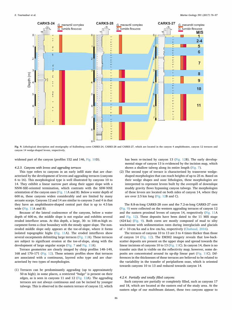
dimentary infill is visible and is characterised by a layered echo type onchirp profiles (Fig. 8D). The lithology of the 7.57-m-long CARKS-24core (Fig. 9) that was located in the amphitheatre-shaped part ofcanyon 4 (Fig. 8A and D) essentially comprises silty mud wackestoneand, in some places, intervals of normally graded fine- to medium-grained carbonate sands. These deposits have been dated to the MIS-5stage (< 120 ka) with sedimentation rates of> 15 cm/ka during in-terglacial periods and those of a few cm/ka during glacial periods(Chabaud, 2016).
In addition, up dip of canyons 3 and 4, the bathymetrical mapdisplays 1- to 2-m-deep downslope shallow linear structures, some ofwhich are captured in amphitheatre-shaped areas (S.1, Fig. 8A and B).These structures are typically 2–3 m deep and 50–100 m wide; they arebetter imaged on EM302 imagery, on which they clearly appear to befilled with low-backscatter deposits (S.1, Fig. 8C). Of particular note isthe presence of a spreading depositional area evidenced by low back-scatter that is associated with S.1 structures that seem to extend to-wards the channelised axis between canyons 3 and 4 (Fig. 8C). Based onthese new observations and those of previous studies (Mullins et al.,1984; Rankey and Doolittle, 2012; Mulder et al., 2017), these structuresare interpreted to represent downslope transfer axes of periplatformooze.
4.2.2. Canyons with up-dip linear partsThis type of canyon is typified by canyons 1, 2 and 5, which com-
prise an up-dip linear part and non-eroded interfluves. Canyon 5 is avery good example of this morphological type (Fig. 10). This slope-confined, 19-km-long canyon is limited by its steep edges, which are upto 80 m high and comprise numerous coalescing arcuate scarps(Fig. 10A). The canyon begins with an up-dip linear incision that cutsthe upper slope (see cross-section profiles a and b in Fig. 10B) andwidens along the middle slope, where it ranges in width from 1.2 km to3 km (profiles b and c). Finally, the canyon narrows again at a waterdepth of 900 m, from 3 km to 1.5 km wide (profile d). The talweg in-cision profile reveals that the maximum depth (150 m) is reached in thewidest part of the canyon, along the middle slope (Fig. 10C). The innerpart of the canyon is characterised by terraces with an elevation ofapproximately 50 m above the bottom of the talweg. In this case, theyare especially well developed; they can reach up to 1.5 km wide andextend over 3.5 km long (profile c, Fig. 10B).
The inner part of canyon 5 can be observed using the four chirpprofiles located close to the bathymetrical cross sections provided inFig. 10B. These profiles reveal that all talweg floors are covered by softsediments, except in the up-dip linear incisions (profile 208). Canyonterraces (profile 146) and some edges (profiles 152 and 146) comprisedeposits generating a slightly layered echo type, with some hyperbolespresent in the steepest areas. These deposits, which are interpreted asperiplatform ooze, are relatively thin but can reach thicknesses of up to20 m (approximated using an average velocity of 1700 m s−1) in the
Fig. 8. Detailed characterisation of amphitheatre-shaped canyons (e.g., canyons 3 and 4). (A) 3D bathymetrical map of canyons 3 and 4 and their associated morphological features. (B)Plan view of bathymetrical map of canyons 3 and 4. (C) Plan view of backscatter imagery of canyons 3 and 4. (D) Chirp seismic profile 152 crossing canyons 3 and 4 in their proximal,amphitheatre-shaped part. Note the location of the CARKS-24 core (see Fig. 9). (E) Representative bathymetric cross-sections (noted a to d) along canyons 3 and 4, moving from theirproximal amphitheatre-shaped parts to their mouths. Both canyons start at a water depth of approximately 550 m with a wide amphitheatre-shaped area, the edges of which are affectedby several arcuate scarps. These two widened sections are connected to each other and the upper slope by a channel that is believed to funnel platform-derived sediments. As: arcuatescarp; Cm: cold-water carbonate mound; Tr: terrace; Cn: canyon; S.1: elongated depression; Tw: talweg.
E. Tournadour et al. Marine Geology 391 (2017) 76–97
85
widened part of the canyon (profiles 152 and 146, Fig. 10D).
4.2.3. Canyons with levees and aggrading terracesThis type refers to canyons in an early infill state that are char-
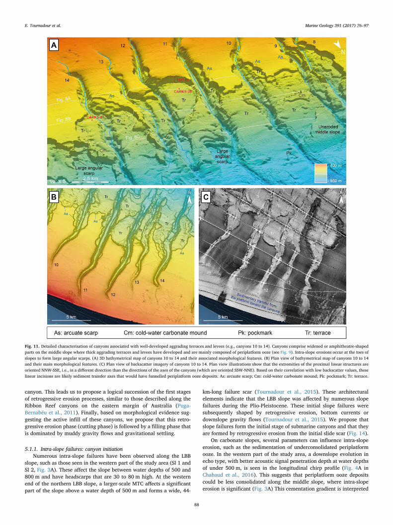
acterised by the development of levees and aggrading terraces (canyons6 to 16). This morphological type is well illustrated by canyons 10 to14. They exhibit a linear narrow part along their upper slope with aNNW-SSE-oriented termination, which contrasts with the SSW-NNEorientation of the canyon axes (Fig. 11A and B). Below a water depth of600 m, these canyons widen considerably and are limited by manyarcuate scarps. Canyons 12 and 14 are similar to canyons 3 and 4 in thatthey have an amphitheatre-shaped central part that is up to 4.5 kmwide (Fig. 11A and B).
Because of the lateral coalescence of the canyons, below a waterdepth of 600 m, the middle slope is not regular and exhibits severaleroded interfluve areas. At this depth, a large, 30- to 100-m-high es-carpment forms a clear boundary with the steady upper slope. The non-eroded middle slope only appears at the toe-of-slope, where it formsisolated topographic highs (Fig. 11A). The eroded interfluves showseveral escarpments delimiting large terraces (Fig. 11A). These terracesare subject to significant erosion at the toe-of-slope, along with thedevelopment of large angular scarps (Fig. 7 and Fig. 11A).
Terrace geometries are clearly imaged by chirp profiles 148–149,168 and 170–171 (Fig. 12). These seismic profiles show that terracesare associated with a continuous, layered echo type and are char-acterised by two types of morphologies.
(1) Terraces can be predominantly aggrading (up to approximately50 m high); in some places, a restricted “bulge” is present on theiredges, as is seen in canyons 11 and 12 (Fig. 12A). The aggradingterraces are not always continuous and can be incised by youngertalwegs. This is observed in the eastern terrace of canyon 12, which
has been re-incised by canyon 13 (Fig. 12B). The early develop-mental stage of canyon 13 is evidenced by the incision map, whichshows a shallow talweg along its entire length (Fig. 7).
(2) The second type of terrace is characterised by transverse wedge-shaped morphologies that can reach heights of up to 25 m. Based ontheir wedge shapes and ooze lithologies, these morphologies areinterpreted to represent levees built by the overspill of downslopemuddy gravity flows bypassing canyon talwegs. The morphologiesof these levees are located on both sides of canyon 14, where theyare over 2.5 km long (Fig. 12B and C).
The 8.8-m-long CARKS-28 core and the 7.2-m-long CARKS-27 core(Fig. 9) were collected on the western aggrading terraces of canyon 12and the eastern proximal levees of canyon 14, respectively (Fig. 11Aand Fig. 12). These deposits have been dated to the 11 MIS stage(424 ka) (Fig. 9). Both cores are mostly composed of mud to siltywackestone with sedimentation rates during interglacials and glacialsof> 10 cm/ka and a few cm/ka, respectively (Chabaud, 2016).
The terraces of canyons 10 to 13 are 3 to 4 times thicker than thoseof canyon 14 (Fig. 12). The EM302 imagery reveals that low-back-scatter deposits are present on the upper slope and spread towards thelinear incisions of canyons 10 to 13 (Fig. 11C). In canyon 14, there is notransfer axis that is visible on the reflectivity map; however, some de-posits are concentrated around its up-dip linear part (Fig. 11C). Dif-ferences in the thicknesses of these terraces are believed to be related tothe variability in the transfer of periplatform ooze, which is orientedtowards canyons 10 to 13 and reduced towards canyon 14.
4.2.4. Partially and totally filled canyonsSuch canyons are partially or completely filled, such as canyons 17
and 18, which are located at the eastern end of the study area. At theeastern edge of our multibeam dataset, these two canyons appear to
Fig. 9. Lithological description and stratigraphy of Kullenberg cores CARKS-24, CARKS-28 and CARKS-27, which are located in the canyon 4 amphitheatre, canyon 12 terraces andcanyon 14 wedge-shaped levees, respectively.
E. Tournadour et al. Marine Geology 391 (2017) 76–97
86

merge in the middle slope and are oriented towards the same mouth(Fig. 13A and B). Canyon 18 is composed of a main talweg and twotributary talwegs (18.1 and 18.2). The main talweg is characterised by aU-shape and low incision depth (up to 70 m). In contrast, the talweg ofcanyon 17 is very steep and can reach depths of up to 130 m. The in-cision depth map reveals that these two talwegs are not continuous andare partially filled below a water depth of 700 m (Fig. 7).
The chirp profiles 283, 277, 201 and 149–150 display the internalstructures of these two canyons (Fig. 13D). In its proximal part, canyon18 comprises a thick sedimentary unit that is characterised by a con-tinuous layered echo type. This sedimentary unit is up to 100 ms twtthick and is thus approximately 80 m thick (profile 277). The talweg ofcanyon 18 appears to crosscut this unit throughout its entire thickness,and the tributary axes 18.1 and 18.2 follow and incise the edges of thissedimentary unit. On the EM302 imagery, this infill is associated withhomogeneous low backscatter values (Fig. 13C). Up-dip of canyon 18, athin sedimentary cover with a slightly layered transparent echo type isinterpreted to be a muddy apron, similar to the Holocene periplatformooze wedge seen on the uppermost slope (Rankey and Doolittle, 2012;Mulder et al., 2017) (profile 283, Fig. 13D). These deposits cover anirregular surface with some incised areas and end with an onlap con-figuration onto the western side of the canyon. The irregular surfaceexhibits an indistinct echo type and high backscatter values; therefore;it is interpreted to represent highly indurated ooze deposits (profile283, Fig. 13D and Fig. 13C).
5. Discussion
5.1. Canyon formation model
The 18 submarine canyons of the northern slope of LBB exhibitsignificant morphological contrasts and can be classified into 4 types.Their architectural differences indicate the diversity of sedimentaryprocesses involved in submarine canyon formation on this purely car-bonate slope. The presence of numerous arcuate slide scarps along thecanyon edges strongly implies that retrogressive erosion processes oc-curred during the early stages of canyon formation (“cutting phase”).On the other hand, the development of levees and aggrading terracescomposed of periplatform ooze suggest the overspill of channelisedmuddy gravity flows and therefore implies that gravity flows producedcanyon infills (“filling phase”). In addition, the present-day seafloorshows numerous distributary furrows that are filled by periplatformooze and oriented towards depositional areas (Figs. 3 and 4), whichfurther supports the presence of small turbidite systems. In this article,we propose a conceptual canyon formation model that highlights therespective effects of erosional and depositional processes on the evo-lution of canyon morphologies based on our observations.
Due to the presence of numerous scarps on the sides of the 18 de-scribed canyons, we propose that slope failures and retrogressive ero-sion are the main processes involved in canyon initiation. The ob-servation of two contrasting canyon shapes, both with and withoutlinear proximal parts, suggests that retrogressive erosion can be ex-pressed to different degrees during the formation and evolution of a
Fig. 10. Detailed characterisation of canyons with up-dip propagating linear incisions (e.g., canyon 5). (A) 3D bathymetrical map of canyon 5 and its associated morphological features.(B) Representative bathymetric cross-sections (noted a to d) along canyon 5, from its up-dip linear incision to its mouth. (C) Comparison of talweg longitudinal profile with interfluveslope profile illustrating incision depth of canyon 5. (D) Chirp seismic profiles 208, 152, 146 and 143 (located in Fig. 6A), showing the along-slope evolution of the internal architecture ofcanyon 5. Steep edges with several arcuate scarps are clearly imaged. The widened part of the canyon is associated with terraces, but their infill is relatively thin (up to 20 m thick). As:arcuate scarp; Cm: cold-water carbonate mound; Tr: terrace.
E. Tournadour et al. Marine Geology 391 (2017) 76–97
87
canyon. This leads us to propose a logical succession of the first stagesof retrogressive erosion processes, similar to those described along theRibbon Reef canyons on the eastern margin of Australia (Puga-Bernabéu et al., 2011). Finally, based on morphological evidence sug-gesting the active infill of these canyons, we propose that this retro-gressive erosion phase (cutting phase) is followed by a filling phase thatis dominated by muddy gravity flows and gravitational settling.
5.1.1. Intra-slope failures: canyon initiationNumerous intra-slope failures have been observed along the LBB
slope, such as those seen in the western part of the study area (Sl 1 andSl 2, Fig. 3A). These affect the slope between water depths of 500 and800 m and have headscarps that are 30 to 80 m high. At the westernend of the northern LBB slope, a larger-scale MTC affects a significantpart of the slope above a water depth of 500 m and forms a wide, 44-
km-long failure scar (Tournadour et al., 2015). These architecturalelements indicate that the LBB slope was affected by numerous slopefailures during the Plio-Pleistocene. These initial slope failures weresubsequently shaped by retrogressive erosion, bottom currents ordownslope gravity flows (Tournadour et al., 2015). We propose thatslope failures form the initial stage of submarine canyons and that theyare formed by retrogressive erosion from the initial slide scar (Fig. 14).
On carbonate slopes, several parameters can influence intra-slopeerosion, such as the sedimentation of underconsolidated periplatformooze. In the western part of the study area, a downslope evolution inecho type, with better acoustic signal penetration depth at water depthsof under 500 m, is seen in the longitudinal chirp profile (Fig. 4A inChabaud et al., 2016). This suggests that periplatform ooze depositscould be less consolidated along the middle slope, where intra-slopeerosion is significant (Fig. 3A) This cementation gradient is interpreted
Fig. 11. Detailed characterisation of canyons associated with well-developed aggrading terraces and levees (e.g., canyons 10 to 14). Canyons comprise widened or amphitheatre-shapedparts on the middle slope where thick aggrading terraces and levees have developed and are mainly composed of periplatform ooze (see Fig. 9). Intra-slope erosions occur at the toes ofslopes to form large angular scarps. (A) 3D bathymetrical map of canyons 10 to 14 and their associated morphological features. (B) Plan view of bathymetrical map of canyons 10 to 14and their main morphological features. (C) Plan view of backscatter imagery of canyons 10 to 14. Plan view illustrations show that the extremities of the proximal linear structures areoriented NNW-SSE, i.e., in a different direction than the directions of the axes of the canyons (which are oriented SSW-NNE). Based on their correlation with low backscatter values, theselinear incisions are likely sediment transfer axes that would have funnelled periplatform ooze deposits. As: arcuate scarp; Cm: cold-water carbonate mound; Pk: pockmark; Tr: terrace.
E. Tournadour et al. Marine Geology 391 (2017) 76–97
88

Fig.
12.(A
)(B)a
nd(C
)represen
tative
chirpprofi
lesof
cany
ons10
to14
(loc
ations
inFig.
11A),thus
illustratingthat
theirinternal
arch
itecturesarech
aracterisedby
thede
velopm
ento
fthick
aggrad
ingterraces
andleve
esbo
rderingcany
ontalw
egs
(Tw).Agg
rading
terraces
canreachthickn
essesof
50m
andaretypically
marke
dby
restricted
bulges
ontheired
ges.Wed
ge-sha
pedleve
esareseen
inthetalw
eged
geof
cany
on14
bute
xhibitless
sign
ificant
thickn
esses.Ana
lysesof
sedimen
tcores
CARKS-27
and28
reve
althat
thesede
position
albe
dformsaremainlyco
mpo
sedof
soft,b
ioturbated
periplatform
ooze
(see
Fig.
9).
E. Tournadour et al. Marine Geology 391 (2017) 76–97
89

as the result of the variable diagenetic potential of the periplatformooze (i.e., high on the upper slope and moderate on the middle slope)combined with the effects of sediment winnowing by bottom currents(Heath and Mullins, 1984; Mullins et al., 1984; Tournadour, 2015;Chabaud et al., 2016).
5.1.2. Retrogressive erosion continuation: canyon formationThe observed morphological contrast between canyons with an up-
dip linear incision above a water depth of 600 m and canyons with awidened part or an amphitheatre shape under a water depth of 600 mcould be the result of a decrease in the intensity of retrogressive erosiondue to an upslope increase in the diagenetic induration of the carbonateooze and/or the decrease in the slope gradient from 2.5° to 1.5° above a
Fig. 13. Detailed characterisation of canyons that are partially or totally filled, e.g., canyons 17 and 18, which comprise an almost totally filled proximal part associated with tributaryaxes (noted as 18.1 and 18.2). Canyons 17 and 18 tend to converge towards the same mouth. A significant sedimentary infill is present in their proximal part and has been re-incised alongthe canyon sides by younger tributary axes. (A) 3D bathymetrical map of canyons 17 and 18 and their associated morphological features. (B) Plan view of bathymetrical map of canyons17 and 18 and their main morphological features. (C) Plan view of backscatter imagery of canyons 17 and 18. (D) Representative chirp profiles of canyons 17 and 18 illustrating theirinternal architectures, which are notably characterised by partial infill (location in Fig. 13A). Cm: cold-water carbonate mound; Tr: terrace; Tw: talweg.
E. Tournadour et al. Marine Geology 391 (2017) 76–97
90

(caption on next page)
E. Tournadour et al. Marine Geology 391 (2017) 76–97
91

water depth of 600 m (Fig. 3B).Canyons 3 and 4, for instance, lack up-dip linear incisions and show
an amphitheatre shape that stops at a water depth of 550 m. The nu-merous arcuate scarps along their edges suggest that they initiallyformed by retrogressive erosion along a single narrow linear incisionthat extends considerably upslope to form proximal amphitheatre-shaped parts (Fig. 8). These amphitheatre-shaped parts also char-acterise canyons 12 and 14. The amphitheatre-shaped canyons are in-terpreted to have formed during a logical succession of retrogressiveerosion processes (Fig. 14). During this stage, retrogressive erosionstopped at a water depth of approximately 550–600 m to form a deepmorphological limit that can be observed throughout the entire studyarea. From canyon 6 to 18, this boundary is evidenced by a continuousescarpment that is up to 100 m high. As this feature was previously seenin the subbottom profiler dataset (Fig. 4A in Chabaud et al., 2016 andFig. 5 in this contribution), we propose that this first morphologicallimit is related to the submarine cementation gradient, which couldimply a change in the transitional up-dip facies from a non-induratedperiplatform ooze towards a nodular ooze facies. Unfortunately, in theeastern part of the study area, the middle slope is rarely preserved andno core data are available with which to confirm this hypothesis. Thepresence of this potential diagenetic front could explain the decrease inretrogressive erosion processes observed along the upper slope. Thisdiagenetic front could cause failures to form on the sides of the canyonsrather than on the upslope part. Consequently, the canyon could be-come enlarged and form the amphitheatre-shaped feature.
In contrast, all canyons except for canyons 3 and 4 are characterisedby an up-dip narrow linear incision between water depths of 450 m and600 m. Once more, the occurrence of numerous scarps on the sides ofthese linear parts suggests that they are mainly formed by retrogressiveerosion. Similar to the previous phase, these again involve retrogressiveerosion progresses; however, these follow a different pattern. At waterdepths that are shallower than 600 m, canyons still expand upslope butonly form narrow linear incisions, probably because the proximal car-bonate deposits are more cemented, thus increasing the shear resistanceof carbonate sediments and the stability of the canyon edges (Fig. 14).Thus, canyons tend to incise rather than to enlarge, leading to the morepronounced entrenchment of incisions. The low penetration echo-typeobserved from 350 to 600 m on the subbottom profiler (Fig. 5) supportsthis hypothesis. In this part, the subbottom profiler is calibrated at awater depth of 600 m by the CARKS-26 core, in which a nodular oozefacies indicates the existence of submarine diagenetic processes. Theretrogressive erosion stage stops at a water depth of approximately450 m, thus forming a second main morphological limit where canyonsdefinitely end. Similar to the first morphological limit, the end of theretrogressive erosion stage is interpreted to represent the result of adownslope facies transition from a hardground facies towards a nodularooze facies, as is suggested by the subbottom profiler dataset, in whichthere is an acoustic facies change from an indistinct echo type towards adiscontinuous layered echo type at a water depth of approximately500 m (Fig. 5A).
Most of the canyons exhibit a V-shape. According to Jobe et al.(2011), this is typical of canyons related to hyperpycnal flows that aredirectly linked with a river mouth. This interpretation is not consistentwith our environmental setting. In the LBB case study, the V-shape iscontrolled by the retrogressive erosion that sometimes affects very ce-mented material. Over time, canyons evolve from being V-shaped tobeing U-shaped because their filling is controlled by depositional
processes involving fine-grained sediment without significant erosion.In other case studies, it has been proposed that downslope eroding
gravity flows could be combined with retrogressive erosion to formsubmarine canyons (e.g., Pratson et al., 1994; Pratson and Coakley,1996). Indeed, the local topography created following intra-slope de-stabilisations can funnel the sediment fluxes coming from the platformand increase the incision of the slope if the flow capacity is high en-ough. In our study, several shallow linear depressions defined as S.1(Fig. 8A, B and C) are observed on the upper slope (Fig. 14), whichcould potentially imply that downslope gravity flows occurred duringthis stage of canyon formation. However, these morphologies arewidespread on the upper slope and are thus not systematically con-nected with the proximal parts of the canyon. Therefore, their origin islikely independent of the formation of the canyon. That said, theseshallow linear depressions strongly suggest that the off-bank transportof active downslope periplatform ooze will ultimately contribute to thecanyon infills. As these shallow linear depressions are present along theentire toe of the prograding wedge, they could also result from localsmall-size avalanching that is initiated along the steepest part of thiswedge.
In the Ribbon Reef Canyons on the eastern margin of Australia(Puga-Bernabéu et al., 2011), which represents the only similar casestudy that is currently comparable with the LBB canyons, it is notablethat retrogressive erosion propagates up to the platform edge until it isfully blocked by reefs. This difference is likely linked to the steepness ofthe slope of the Australian margin (which ranges from 7° to 15°)compared to the gentler LBB slope (which ranges from 1.5° to 2.5°).
5.1.3. Canyon infill by periplatform oozeCanyons 10 to 14 are bordered by aggrading terraces that are ty-
pically associated with wedge-shaped levees (Figs. 11 and 12). Thesemorphologies are composed of not indurated, bioturbated periplatformooze with a mud to silty wackestone texture (CARKS-27 and 28 Fig. 9,located in Figs. 11A and 12).
The off-bank transport from the platform towards the canyons wasrecently characterised on the uppermost slope (at a water depth of>300 m) by Mulder et al. (2017). These authors showed the presence ofshallow tidal channels connected to linear incisions of submarine can-yons that directly feed these canyons with platform-derived sediments,thus forming low-density currents. The transported sediments mostlyconsist of periplatform ooze, thus suggesting that these flows transportplatform sediments mixed with fall-out sediments that can be in-corporated during transport. Canyon terraces and levees appear tomainly comprise by the overbank of the dilute upper parts of theseflows, which are therefore partly confined within the canyon talweg(Fig. 14). Canyon 13 was developed by the incision of the eastern ter-race of canyon 12 (Figs. 11 and 12). These morphological featuressuggest that a new canyon can be formed by the subsequent bypassingof muddy gravity flows across a previous deposited muddy infill.
Canyons 17 and 18 are characterised by the presence of a dis-tributary axis connected with the up-dip linear parts of canyons. Thisproximal domain is largely filled by periplatform ooze (Fig. 13). Thesecanyons are interpreted to be the result of the advanced filling stagewhere new tributary axes develop within the proximal part of thecanyon (Fig. 14); this points to the intensification of the sediment fluxesthat are funnelled within the canyons. Of particular interest in canyons17 and 18 is that the orientations of these canyons differ from those thatare located approximately 10° to the east. Moreover, they have the
Fig. 14. Theoretical model for LBB canyon formation and evolution from canyon initiation to infill. Based on our morphological classification, this model comprises five evolutionarystages, each of which is illustrated by a representative morphological example. Canyon initiation is thought to essentially result from slope failures occurring on the middle slope.Following this, canyons propagate up-slope due to two successive phases of stepped retrogressive erosion controlled by a submarine cementation gradient that decreases downslope. Thefirst phase of retrogressive erosion leads to the widening of canyons up to a water depth of 600 m, whereas the second phase forms linear incisions up to a water depth of 450 m, where itis stopped by a sedimentary facies transition between a nodular ooze facies and a hardground facies. Subsequently, after this mostly erosional phase, muddy gravity flows are responsiblefor canyon infill, which is associated with the formation of aggrading terraces and levees. This infill phase eventually leads to the onset of the final blanketing of the canyon, marking theend of the “erosion-fill” cycle.
E. Tournadour et al. Marine Geology 391 (2017) 76–97
92

same orientation as tidal passes associated with oolitic shoals to the eastof Carter's Cay (Figs. 6A and 7). This leads us to suggest that theproximal parts of canyons are located in front of a major transfer axis ofperiplatform ooze, which could explain their current advanced degreeof infill (Fig. 13).
The distributary furrows suggest that the by-pass of sediment fluxesalong the lower slope from the canyon mouths towards the three distaldepositional areas (Fig. 4A and C). The low backscatter that char-acterises the shallow distributary furrows suggests that they are filledby fine-grained or not indurated sediments and could be thus formed bycut and fill processes. Along with such downslope sediment transfers,the linear structures seen on the acoustic imagery ranging from N°300to N°270 (Fig. 4B) attest to the role that bottom currents play in thesedimentary dynamics occurring in the eastern part of the study area.The SE-NW-flowing Antilles Current could have enough capacity toform these linear structures and therefore trap some of the fine-grainedsediments originating from muddy gravity flows at the canyon mouths.Then, these deep sea bank-derived sediments could participate in theLBB drift growth (Tournadour et al., 2015; Chabaud et al., 2016). An-other hypothesis is that linear morphologies are the result of the dee-pest circulation of the Labrador Sea Water, which could transport se-diments towards the deep basin.
The trapping of sediment by bottom currents could explain the re-latively reduced sediment rates on the lower slope during the Plio-Pleistocene (33 m/m.y. at ODP site 628 and 14–15 m/m.y. at ODP site627) compared to the middle slope (62 m/m.y. at ODP site 630 (Austinet al., 1986)) despite the architectural evidence of the downslope by-pass.
The lack of such a filling stage in the active canyons of theAustralian Great Barrier Reef margin is another stark difference withthe LBB canyons. This discrepancy could be explained by the steepnessof the Australian slope, which could induce a dominantly erosionalprocess and potentially completely bypass sediments in transit in thecanyons. In addition, a less productive “carbonate factory” on theeastern Australian margin than on LBB could also explain its weaker off-bank transport and thus the availability of fewer sediments to fill thecanyons.
5.2. Control parameters on canyon evolution along the LBB slope
The proposed theoretical model of the evolution of the canyon, frominitiation to infill, is characterised by the specific sedimentary processesand architectures summarised in Fig. 15. These include three mainstages of evolution occurring at three different time periods: (1) in-itiation caused by intra-slope destabilisations, (2) up-slope migration byretrogressive erosion, and (3) canyon infill by periplatform ooze. Here,we address the potential control parameters for each of these three timeperiods.
(1) This dataset suggests that canyon initiation results from slope fail-ures. Several submarine slides have been observed along the middleslope of LBB; these show numerous arcuate scarps on their steepedges, thus suggesting a continuum to canyon formation throughretrogressive erosion processes. Large submarine slides frequentlyoccurred along the accretionary Bahamian slopes during particularperiods of the Neogene (Austin et al., 1988; Schlager et al., 1988; Joet al., 2015; Principaud et al., 2015; Tournadour et al., 2015), butcorrespond to various triggering mechanisms. Slope failures couldhave been triggered by high sedimentation rates, the intensificationof bottom currents or earthquakes.- The LBB submarine canyons appear to have formed during aperiod of high slope aggradation linked to high carbonate pro-duction on the platform in the Pliocene (Austin et al., 1988;Harwood and Towers, 1988; McNeill et al., 1998; Tournadour,2015). Submarine landslides could therefore have been triggeredby sediment overloading.
- The northern slope of LBB is strongly influenced by the SE-NW-flowing Antilles Current (Tournadour et al., 2015; Chabaud,2016). The intensification of the Antilles current could have en-hanced the shear stress on the middle slope and favoured thetriggering of slides.
- Earthquakes can be another triggering mechanism for large slidesalong the slope. Indeed, Jo et al. (2015) attributed the margincollapse of the southwestern margin of GBB to the tectonic ac-tivity in the vicinity of the Cuban fold and thrust belt. Althoughthe northern slope of LBB is located relatively far from the Cubanfold and thrust belt, several studies have interpreted severalnormal faults or tectonic tilts as being related to the Cuban or-ogenesis (Mullins et Van Buren, 1981; Van Buren and Mullins,1983; Mulder et al., 2012b).
In addition to these triggering parameters, preconditioning factorscould also favour slope failures. Indeed, submarine landslides could belinked to the presence of cemented surfaces generated by early diag-enesis, which typically occurs during lowstand periods (Malone et al.,2001). These well-lithified surfaces could form a preferential detach-ment horizon and a gliding plane for the sliding sediments. For ex-ample, along the western slope of GBB, Principaud et al. (2016) iden-tified the Late Messinian–Early Pliocene horizon as a commondetachment surface of the Plio-Pleistocene MTCs. Moreover, Harwoodand Towers (1988) identified numerous detachment surfaces along theLBB slope in the Pliocene-Holocene interval that likely controlled large-scale rotational movements and slumped masses (Fig. 2B).
(2) The up-slope migration by retrogressive erosion includes two con-ceptual steps that control the morphological contrasts between theamphitheatre shapes at water depths ranging from 650 m to 800 mand the linear V-shaped incisions at water depths ranging from450 m to 600 m. These two backstepping stages could be diachro-nous or coeval to the initiation of the canyon due to slope failures.In this case study, it is not possible to determine the relative timingof these steps. Moreover, our dataset does not allow us to identifyany preferential period for the formation of V-shaped incisions(e.g., lowstand vs highstand periods). However, V-shaped incisionshave been identified on the western slope of GBB, which have beendated to the Messinian and Early Pliocene and are associated with arelative sea level drop (Anselmetti et al., 2000; Principaud et al.,2016). In addition, Wunsch et al. (2017) interpreted that the trig-gering of failures occurred on the leeward slope of the GBB duringthe last sea-level fall.
The triggering mechanisms of such retrogressive erosions have beenattributed to downslope eroding gravity flows in many other case stu-dies (Pratson and Coakley, 1996). However, in this context, it remainsdifficult to distinguish between gravity-driven intra-slope erosion anddownslope erosion caused by gravity flows that were initiated from theplatform edge during canyon formation. That said, in this purely car-bonate setting, it seems unlikely that gravity flows generated at theplatform edge would have had sufficient intensity to cause seawardexcavation.
(3) Under the current highstand shedding settings, carbonate produc-tion on the platform is believed to be maximal and the intensity ofplatform-derived sediment fluxes is expected to increase movingtowards deep sea environments (Droxler and Schlager, 1985;Grammer and Ginsburg, 1992; Schlager et al., 1994; Jorry et al.,2010). However, the transfer of periplatform ooze is not uniformalong the slope, i.e., significant alongshore variability must beconsidered when dealing with platform-basin sediment transfer. OnLBB, the latter is significant on the leeward western platformmargin, where there are no barrier reefs, but it progressively de-creases towards the windward eastern margin, which is associated
E. Tournadour et al. Marine Geology 391 (2017) 76–97
93

with discontinuous barrier reefs (Fig. 3A). Periplatform ooze isbelieved to be transported by either density cascading or muddygravity flows confined within canyons. Present sea level highstandconditions have led to the flooding of the platform (between 3 and8 m) but remains lesser than that recorded during earlier inter-glacials, such as MIS5e. During this latter extreme highstand, thecomplete flooding of the platform generated the full activity of thecarbonate factory and increased carbonate production and off-banktransport (Chabaud et al., 2016; Chabaud, 2016). The presence ofconfined turbidite levees suggests that muddy flows may play animportant role in canyon differentiation during the filling stages.The intensification of canyon infill may be linked to the develop-ment of preferential transfer axes for muddy gravity flows, parti-cularly when the sea level is higher than the present sea level(Chabaud, 2016). The carbonate exports can also supply a high-stand wedge, such as the Holocene wedge, along the uppermostslope of LBB (Rankey and Doolittle, 2012). The export processes ofthe periplatform ooze appear to be linked to the tidal dynamicslocated near the passes and, to some extent, towards canyons
(Mulder et al., 2017). In addition, the Antilles current or/and theLabrador Sea Water, which circulate along the LBB slope, can alsolimit the infill of the submarine canyons by reworking fine-grainedsediments, in addition to increasing carbonate cementation.
5.3. Comparison with other submarine canyons of the Bahamian slopes
The Bahamian slopes are characterised by several downslope by-pass features indicating the transfer of sediments from platforms to-wards deep basins (Table 1). In this comparison, we only considercanyons that are located between water depths of 0 to 1000 m (referredto as “accretion” sensu Schlager and Ginsburg, 1981), in contrast tothose that are located along the U.S. East Coast continental margin,which are located at water depths ranging from 2000 to 4000 m (re-ferred to as “erosion” sensu Schlager and Ginsburg, 1981), such as theGreat Abaco Canyon and the San Salvador Canyon (Mullins et al., 1982;Ravenne et al., 1985).
The downslope by-pass architectures have been described (that are50 to 200 m deep) on the southern slope of LBB by Burns and Neumann
Fig. 15. Summary diagram illustrating the platform morphologies and associated architectural styles of LBB canyons relative to their main control parameters (i.e., gravity destabili-sations and sediment fluxes).
E. Tournadour et al. Marine Geology 391 (2017) 76–97
94

(1987). These were studied using only chirp profiles and their detailedgeometries are still poorly known; thus, we cannot comprehensivelycompare them to the canyons described in this paper. Other canyonshave been identified on the western slope of GBB as V-shaped incisionsusing 2D seismic profiles; these were interpreted as being related torelative sea-level falls during the Messinian and the Pliocene withoutspecifying any formation processes (sequence f in Anselmetti et al.,2000; Me and PL-1 surfaces in Principaud et al., 2016). These incisions,which are 0.05 to 0.15 s twt deep, are currently completely filled. Asecond type of downslope by-pass geometries, called “gullies”, havebeen very well-imaged on the present-day sea floor of the western slopeof GBB (Mulder et al., 2012a; Betzler et al., 2014; Wunsch et al., 2017).These incisions are located on the slope at water depths between 400 mand 700 m, are 10 to 20 m deep and are generally associated with se-diment waves. They have been interpreted as structures related todensity cascading processes (Wilson and Roberts, 1992, 1995), whichare believed to be most active during relative sea level highstands,when carbonate production is maximal (Betzler et al., 2014; Wunschet al., 2017). In addition, on the east windward slope of Cay Sal Bank(CSB), several channels are present on the seafloor at water depthsranging from 300 to 700 m, with incisions at depths of 10 to 60 m; thesechannels are characterised by dendritic patterns at their upslope ends(Wunsch et al., 2017). The authors proposed that channels on thiswindward slope have been formed by turbidity currents induced bysurface currents during relative sea-level lowstands.
Compared to all of these features, canyons on the northern slope ofLBB exhibit very atypical shapes; very few, if any, morphologies aresimilar to those of the other present-day Bahamian slopes. However,despite their atypical shapes, their dimensions are comparable to thoseof the buried canyons (i.e., V-shaped incisions) observed on the westernslope of GBB and the channels on the windward slope of CSB (Table 1).The latter are interpreted to have been formed during lowstand periodswith increased sediment fluxes coming from the platform. According tothese authors, the associated gravity flows could have been strong en-ough to erode the slope and produce submarine canyons (Wunsch et al.,2017). In our case study, downslope gravity flow erosion has not yetbeen ruled out as a cause of canyon formation, but it appears unlikelythat gravity flows alone could generate incisions that are> 100 mdeep. Moreover, the numerous slide scars on the edges of canyons re-present compelling evidence for the role of retrogressive erosion pro-cesses in canyon formation. Therefore, we consider that muddy gravityflows play a larger role in the infill of canyons than in their initialformation.
6. Conclusions
The submarine canyons on the northern slope of LBB constitute aunique case study that can be used to improve our understanding ofcanyon formation in purely carbonate settings. Using a very high-re-solution dataset, we are able to provide new constraints on themorphologies, evolution and initiation of the LBB northern slope can-yons. This allows us to discuss their control parameters.
Canyons can been classified as one of four morphological types:canyons ending with an amphitheatre-shaped part (1); canyons ex-panding upslope by deep linear incisions (2); canyons associated withaggrading terraces and levees (3); and canyons that are partially orcompletely filled (4). Due to progressive filling, the transversal profilesof canyons progressively evolve from being V-shaped to being U-shaped. Based on these main morphologies, their distributions on slopesand their internal architecture, we propose a detailed model for theformation and evolution of carbonate slope canyons. Canyons are be-lieved to be initiated by slope failures that propagate upslope due totwo successive stages of retrogressive erosion. The first retrogressiveerosion stage produces the widened shape or amphitheatre shape ofcanyons that progress up-slope up to water depths of 600 m. The secondstage of retrogressive erosion leads to the formation of linear incisionsup to water depths of 450 m. Then, the filling of canyons by muddygravity flows and gravitational settling forms aggrading terraces andwedge-shaped levees. This filling process eventually leads to the onsetof canyon blanketing.
The present canyon morphology is a result of cut and fill phases.This model therefore suggests that canyon formation in such settings isessentially controlled by retrogressive erosion processes, as is evidencedby the numerous arcuate scarps located on the sides of the canyon. Thisstudy demonstrates the key role that carbonate lithology plays incanyon evolutions that are driven by retrogressive erosion. Indeed, weshow that a downslope gradient of submarine cementation controlsretrogressive erosion patterns, which induce very specific morpholo-gical contrasts between LBB canyons. Canyon infill, which is dominatedby periplatform ooze, represents the result of pelagic sedimentationcombined with the deposition of sediments by non-erosive muddygravity flows initiated from the platform edge, as is suggested by thepresence of wedge-shaped levees and confined aggrading terraceswithin canyons. Filling by periplatform ooze and fine-grained turbiditeprobably occur during different highstand periods, depending of theheight of the water flooding the platform and the related productivity ofthe carbonate factory. Available sediments involved in the canyon in-fills are thus mainly controlled by the production of the carbonate
Table 1Synthesis of the morphologies and process interpretations of presently known downslope by-pass architectures along the Bahamian slopes (up to 1000 m water depth).
Localisation Type Water depth Incisiondepth
Description Interpretation References
Northern slope of LittleBahama Bank (LBB)
Canyons From 450 to1000 m
100 to150 m
Canyons with an up-dip linearincision and an amphitheatre-shaped head.
Canyon formation mainly controlled byretrogressive erosion.
-Mulder et al., 2012b-This study
Southern slope of LittleBahama Bank (LBB)
Inactivecanyons
10 to 200 m Interpreted as erosional features created byturbidity currents and other gravity-drivensediment flows. Occur sporadically.
-Burns and Neumann,1987
Western slope of GreatBahama Bank(GBB)
Buriedcanyons
0.05 to0.15 s twt
V-shaped incisions observed on2D seismic profiles
Interpreted as being related to a relativesea-level fall.
-Anselmetti et al., 2000-Principaud et al., 2016
Western slope of GreatBahama Bank(GBB)
Seafloorgullies
From 400 to700 m
10 to 20 m Seafloor gullies, generallyassociated with sedimentwaves.
Interpreted as structures linked to densitycascading processes, mostly during relativesea-level highstands.
-Wilson and Roberts,1992, Wilson andRoberts, 1995-Mulder et al., 2012a-Betzler et al., 2014-Wunsch et al., 2017
East windward slope ofCay Sal Bank (CSB)
Channels From 300 to700 m
10 to 60 m Channels characterised by adentritic pattern at theirupslope end.
Formed by turbidity currents induced bysurface currents during relative sea-levellowstands.
-Wunsch et al., 2017
E. Tournadour et al. Marine Geology 391 (2017) 76–97
95

platform. However, the spatial distribution of the platform-derived se-diment fluxes is not uniform along the slope. There is indeed a strongalongshore variability in off-bank transport that is closely linked withthe orientation of the platform with respect to wind direction andoceanic current circulation and the relative continuity of the reef bar-rier. Sedimentary fluxes are dominant in the leeward western platformmargin, which contains no barrier reefs; these fluxes progressively de-crease moving towards the windward eastern margin, which is asso-ciated with discontinuous barrier reefs. In addition, variations are alsocaused by the remobilisation of fine particles by the surface Antillescurrent heading towards the northwestern part of the LBB slope and/orthe bottom Labrador Current heading towards the southeastern part ofthe LBB slope. Therefore, the preservation of LBB canyons since thePliocene could be the result of relatively low sedimentation rates alongtheir windward margins and/or the result of the by-pass of platform-derived sediment flows in the canyon talweg towards the deep basin.
Akcnowledgements
We thank the captain and the crew of the R/V Le Suroît for thequality of the data acquired during the Carambar cruise 1. We ac-knowledge TOTAL for their support and their scientific contribution tothis project. We also thank to two anonymous reviewers for theircomments and suggestions which improved the early version of thismanuscript.
References
Anselmetti, F.S., Eberli, G.P., Ding, Z.-D., 2000. From the Great Bahama Bank into theStraits of Florida: a margin architecture controlled by sea-level fluctuations and oceancurrents. Geol. Soc. Am. Bull. 112, 829–844.
Austin, J.A., Schlager, W., Palmer, A.A., Comet, P.A., Droxler, A., Eberli, G.P., Fourcade,E., Freeman-Lynde, R., Fulthorpe, C.S., Harwood, G., Kuhn, G., Lavoie, D., Leckie, M.,Melillo, A.J., Moore, A., Mullins, H.T., Ravenne, C., Sager, W.W., Swart, P., Verbeek,J.W., Watkins, D.K., Williams, C., 1986. Proc. ODP Initial Report. vol. 101.
Austin, J.A., Schlager, W., Palmer, A.A., Comet, P.A., Droxler, A., Eberli, G.P., Fourcade,E., Freeman-Lynde, R., Fulthorpe, C.S., Harwood, G., Kuhn, G., Lavoie, D., Leckie, M.,Melillo, A.J., Moore, A., Mullins, H.T., Ravenne, C., Sager, W.W., Swart, P., Verbeek,J.W., Watkins, D.K., Williams, C., 1988. Proc. Scientific Results. vol. 101.
Ball, M.M., 1967. Carbonate sand bodies of Florida and the Bahamas. J. Sediment. Res.37, 556–591.
Benson, W.E., Sheridan, R.E., Pastouret, L., Enos, P., Freeman, T., Murdmaa, I.O.,Worstell, P., Gradstein, F., Schmidt, R.R., Weaver, F.M., Stuermer, D.H., 1975. InitialReports of the Deep Sea Drilling Project. vol. XLIV (Leg 44).
Betzler, C., Lindhorst, S., Eberli, G.P., Lüdmann, T., Möbius, J., Ludwig, J., Schutter, I.,Wunsch, M., Reijmer, J.J.G., Hübscher, C., 2014. Periplatform drift: the combinedresult of contour current and off-bank transport along carbonate platforms. Geology42, 871–874.
Bliefnick, D.M., Robertson, A.H.F., Sheridan, R.E., 1983. Deposition and provenance ofMiocene intraclastic chalks, Blake-Bahama Basin, western North Atlantic. In: InitialReports DSDP, Leg 76, Norfolk to Fort Lauderdale, pp. 727–748.
Burns, S.J., Neumann, A.C., 1987. Pelagic sedimentation on an inactive gullied slope,northwest providence channel, Bahamas. Mar. Geol. 277–286.
Canals, M., Puig, P., de Madron, X.D., Heussner, S., Palanques, A., Fabres, J., 2006.Flushing submarine canyons. Nature 444, 354–357.
Chabaud, L., 2016. Modèle stratigraphique et processus sédimentaires au Quaternaire surdeux pentes carbonatées des Bahamas (leeward et windward). Université deBordeaux.
Chabaud, L., Ducassou, E., Tournadour, E., Mulder, T., Reijmer, J.J.G., Conesa, G.,Giraudeau, J., Hanquiez, V., Borgomano, J., Ross, L., 2016. Sedimentary processesdetermining the modern carbonate periplatform drift of Little Bahama Bank. Mar.Geol. 378, 213–229.
Chérubin, L.M., 2014. High-resolution simulation of the circulation in the Bahamas andTurks and Caicos Archipelagos. Prog. Oceanogr. 127, 21–46.
Damuth, J.E., Hayes, D.E., 1977. Echo character of the East Brazilian continental marginand its relationship to sedimentary processes. Mar. Geol. 24, 73–95.
Droxler, A.W., Schlager, W., 1985. Glacial versus interglacial sedimentation rates andturbidite frequency in the Bahamas. Geology 13, 799–802.
Enos, P., 1974. Surface Sediment Facies Map of the Florida–Bahamas Plateau. GeologicalSociety of America (Map 5).
Ericson, D.B., Wollin, G., 1956. Micropaleontological and isotopic determinations ofPleistocene climates. Micropaleontology 2, 257–270.
Ericson, D.B., Ewing, M., Wollin, G., Heezen, B.C., 1961. Atlantic deep-sea sedimentcores. Geol. Soc. Am. Bull. 72, 193–286.
Evans, H.K., Hall, I.R., Bianchi, G.G., Oppo, D.W., 2007. Intermediate water links to DeepWestern Boundary current variability in the subtropical NW Atlantic during MarineIsotope stages 5 and 4. Paleoceanography 22. http://dx.doi.org/10.1029/
2006PA001409.Exon, N.F., Hill, P.J., Mitchell, C., Post, A., 2005. Nature and origin of the submarine
Albany canyons off southwest Australia. Aust. J. Earth Sci. 52, 101–115.Grammer, G.M., Ginsburg, R.N., 1992. Highstand versus lowstand deposition on carbo-
nate platform margins: insight from Quaternary foreslopes in the Bahamas. Mar.Geol. 103, 125–136.
Harris, P.T., Whiteway, T., 2011. Global distribution of large submarine canyons: geo-morphic differences between active and passive continental margins. Mar. Geol. 285,69–86.
Harwood, G.M., Towers, P.A., 1988. Seismic sedimentological interpretation of a carbo-nate slope, north margin of Little Bahama Bank. In: Proc. ODP Sci. Results. vol. 101.pp. 263–277.
Heath, K.C., Mullins, H.T., 1984. Open-ocean, off-bank transport of fine-grained carbo-nate sediment in the Northern Bahamas. Geol. Soc. Lond., Spec. Publ. 15, 199–208.
Huneke, H., Mulder, T., 2010. Deep-sea Sediments. Elsevier.Jo, A., Eberli, G.P., Grasmueck, M., 2015. Margin collapse and slope failure along
southwestern Great Bahama Bank. Sediment. Geol. 317, 43–52.Jobe, Z.R., Lowe, D.R., Uchytil, S.J., 2011. Two fundamentally different types of sub-
marine canyons along the continental margin of Equatorial Guinea. Mar. Pet. Geol.28, 843–860.
Jorry, S.J., Droxler, A.W., Francis, J.M., 2010. Deepwater carbonate deposition in re-sponse to re-flooding of carbonate bank and atoll-tops at glacial terminations. Quat.Sci. Rev. 29, 2010–2026.
Kaczmarek, S.E., Hicks, M.K., Fullmer, S.M., Steffen, K.L., Bachtel, S.L., 2010. Mappingfacies distributions on modern carbonate platforms through integration of multi-spectral Landsat data, statistics-based unsupervised classifications, and surface sedi-ment data. AAPG Bull. 94, 1581–1606.
Lewis, K.B., Barnes, P.M., 1999. Kaikoura Canyon, New Zealand: active conduit fromnear-shore sediment zones to trench-axis channel. Mar. Geol. 162, 39–69.
Malone, M.J., Slowey, N.C., Henderson, G.M., 2001. Early diagenesis of shallow-waterperiplatform carbonate sediments, leeward margin, Great Bahama Bank (OceanDrilling Program Leg 166). Geol. Soc. Am. Bull. 113, 881–894.
Mazières, A., Gillet, H., Castelle, B., Mulder, T., Guyot, C., Garlan, T., Mallet, C., 2014.High-resolution morphobathymetric analysis and evolution of Capbreton submarinecanyon head (Southeast Bay of Biscay—French Atlantic Coast) over the last decadeusing descriptive and numerical modeling. Mar. Geol. 351, 1–12.
McNeill, D.F., Grammer, G.M., Williams, S.C., 1998. A 5 MY chronology of carbonateplatform margin aggradation, southwestern Little Bahama Bank, Bahamas. J.Sediment. Res. 68, 603–614.
Mitchell, J.K., Holdgate, G.R., Wallace, M.W., Gallagher, S.J., 2007. Marine geology ofthe Quaternary Bass Canyon system, southeast Australia: a cool-water carbonatesystem. Mar. Geol. 237, 71–96.
Mulder, T., Syvitski, J.P.M., Migeon, S., Faugères, J.-C., Savoye, B., 2003. Marine hy-perpycnal flows: initiation, behavior and related deposits. a review. Mar. Pet. Geol.20, 861–882.
Mulder, T., Ducassou, E., Eberli, G.P., Hanquiez, V., Gonthier, E., Kindler, P., Principaud,M., Fournier, F., Léonide, P., Billeaud, I., Marsset, B., Reijmer, J.J.G., Bondu, C.,Joussiaume, R., Pakiades, M., 2012a. New insights into the morphology and sedi-mentary processes along the western slope of Great Bahama Bank. Geology 40,603–606.
Mulder, T., Ducassou, E., Gillet, H., Hanquiez, V., Tournadour, E., Combes, J., Eberli,G.P., Kindler, P., Gonthier, E., Conesa, G., Robin, C., Sianipar, R., Reijmer, J.J.G.,François, A., 2012b. Canyon morphology on a modern carbonate slope of theBahamas: evidence of a regional tectonic tilting. Geology 40, 771–774.
Mulder, T., Joumes, M., Hanquiez, V., Gillet, H., Reijmer, J.J.G., Tournadour, E.,Chabaud, L., Principaud, M., Schnyder, J.S.D., Borgomano, J., Fauquembergue, K.,Ducassou, E., Busson, J., 2017. Carbonate slope morphology revealing sedimenttransfer from bank-to-slope (Little Bahama Bank, Bahamas). Mar. Pet. Geol. 83,26–34.
Mullins, H.T., Mark Van Buren, H., 1981. Walkers Cay Fault, Bahamas: Evidence forCenozoic faulting. Geo-Marine Letters 1 (3), 225–231.
Mullins, H.T., Neumann, A.C., 1979. Deep carbonate bank margin structure and sedi-mentation in the Northern Bahamas. In: Geology of Continental Slopes. vol. 27.SEPM Society for Sedimentary Geology, pp. 165–192.
Mullins, H.T., Keller, G.H., Kofoed, J.W., Lambert, D.N., Stubblefield, W.L., Warme, J.E.,1982. Geology of Great Abaco Submarine Canyon (Blake Plateau): observations fromthe research submersible “Alvin”. Mar. Geol. 48, 239–257.
Mullins, H.T., Heath, K.C., Van Buren, H.M., Newton, C.R., 1984. Anatomy of a modernopen-ocean carbonate slope: northern Little Bahama Bank. Sedimentology 31,141–168.
Neumann, A.C., Land, L.S., 1975. Lime mud deposition and calcareous algae in the Bightof Abaco, Bahamas; a budget. J. Sediment. Res. 45, 763–786.
Normark, W.R., Carlson, P.R., 2003. Giant submarine canyons: is size any clue to theirimportance in the rock record? Geol. Soc. Am. Spec. Pap. 370, 175–190.
Pratson, L.F., Coakley, B.J., 1996. A model for the headward erosion of submarine can-yons induced by downslope-eroding sediment flows. Geol. Soc. Am. Bull. 108,225–234.
Pratson, L.F., Ryan, W.B.F., Mountain, G.S., Twichell, D.C., 1994. Submarine canyoninitiation by downslope-eroding sediment flows: evidence in late Cenozoic strata onthe New Jersey continental slope. Geol. Soc. Am. Bull. 106, 395–412.
Principaud, M., Mulder, T., Gillet, H., Borgomano, J., 2015. Large-scale carbonate sub-marine mass-wasting along the northwestern slope of the Great Bahama Bank(Bahamas): morphology, architecture, and mechanisms. Sediment. Geol. 317, 27–42.
Principaud, M., Ponte, J.-P., Mulder, T., Gillet, H., Robin, C., Borgomano, J., 2016. Slope-to-basin stratigraphic evolution of the northwestern Great Bahama Bank (Bahamas)during the Neogene to Quaternary: interactions between downslope and bottom
E. Tournadour et al. Marine Geology 391 (2017) 76–97
96

currents deposits. Basin Res (in press).Puga-Bernabéu, Á., Webster, J.M., Beaman, R.J., Guilbaud, V., 2011. Morphology and
controls on the evolution of a mixed carbonate–siliciclastic submarine canyon system,Great Barrier Reef margin, north-eastern Australia. Mar. Geol. 289, 100–116.
Puga-Bernabéu, Á., Webster, J.M., Beaman, R.J., Guilbaud, V., 2013. Variation in canyonmorphology on the Great Barrier Reef margin, north-eastern Australia: the influenceof slope and barrier reefs. Geomorphology 191, 35–50.
Puga-Bernabéu, Á., Webster, J.M., Beaman, R.J., Reimer, P.J., Renema, W., 2014. Fillingthe gap: a 60 ky record of mixed carbonate-siliciclastic turbidite deposition from theGreat Barrier Reef. Mar. Pet. Geol. 50, 40–50.
Purkis, S.J., Harris, P.M., 2016. The extent and patterns of sediment filling of accom-modation space on great Bahama Bank. J. Sediment. Res. 86, 294–310.
Rankey, E.C., Doolittle, D.F., 2012. Geomorphology of carbonate platform-marginal up-permost slopes: insights from a Holocene analogue, Little Bahama Bank, Bahamas.Sedimentology 7, 2146–2171.
Rankey, E.C., Doolittle, D.F., 2012. Geomorphology of carbonate platform-marginal up-permost slopes: insights from a Holocene analogue, Little Bahama Bank, Bahamas.Sedimentology.
Ravenne, C., Le Quellec, P., Valery, P., 1985. Dépôts carbonatés profonds des Bahamas.In: Géodynamique des caraïbes. Symposium. Edition Technip, Paris, pp. 255–271.
Reeder, S.L., Rankey, E.C., 2008. Interactions between tidal flows and ooid shoals,Northern Bahamas. J. Sediment. Res. 78, 175–186.
Reeder, S.L., Rankey, E.C., 2009. Controls on morphology and sedimentology of carbo-nate tidal deltas, Abacos, Bahamas. Mar. Geol. 267, 141–155.
Schlager, W., Ginsburg, R.N., 1981. Bahama carbonate platforms-the deep and the past.Mar. Geol. 44, 1–24.
Schlager, W., James, N.P., 1978. Low-magnesian calcite limestones forming at the deep-sea floor, Tongue of the Ocean, Bahamas. Sedimentology 25, 675–702.
Schlager, W., Bourgeois, F., Mackenzie, G., Smit, J., 1988. Boreholes at Great Isaac andSite 626 and the history of the Florida Straits. Proc., scientific results, ODP, Leg 101,Bahamas 425–437.
Schlager, W., Reijmer, J.J.G., Droxler, A., 1994. Highstand shedding of carbonate plat-forms. J. Sediment. Res. 64, 270–281.
Shepard, F.P., 1936. The underlying causes of submarine canyons. Proc. Natl. Acad. Sci.U. S. A. 22, 496–502.
Shepard, F.P., 1981. Submarine canyons; multiple causes and long-time persistence.AAPG Bull. 65, 1062–1077.
Shepard, F.P., Dill, R.F., Vonrad, U., 1969. Physiography and sedimentary processes of LaJolla submarine fan and fan-valley, California. AAPG Bull. 53, 390–420.
Tournadour, E., 2015. Architecture et dynamique sédimentaire d'une pente carbonatéemoderne: exemple de la pente nord de Little Bahama Bank (LBB), Bahamas. EdBordeaux University.
Tournadour, E., Mulder, T., Borgomano, J., Hanquiez, V., Ducassou, E., Gillet, H., 2015.Origin and architecture of a Mass Transport Complex on the northwest slope of LittleBahama Bank (Bahamas): relations between off-bank transport, bottom current se-dimentation and submarine landslides. Sediment. Geol. 317, 9–26.
Van Buren, H.M., Mullins, H.T., 1983. Seismic stratigraphy and geologic development ofan open-ocean carbonate slope; the northern margin of Little Bahama Bank. In:Sheridan, R.E., Gradstein, F.M. (Eds.), Init. Repts. DSDP, 76. U.S. Govt. PrintingOffice, Washington, pp. 749–762.
Webster, J.M., Beaman, R.J., Puga-Bernabéu, Á., Ludman, D., Renema, W., Wust, R.A.J.,George, N.P.J., Reimer, P.J., Jacobsen, G.E., Moss, P., 2012. Late Pleistocene historyof turbidite sedimentation in a submarine canyon off the northern Great Barrier Reef,Australia. Palaeogeogr. Palaeoclimatol. Palaeoecol. 331–332, 75–89.
Wilson, P.A., Roberts, H.H., 1992. Carbonate-periplatform sedimentation by densityflows: a mechanism for rapid off-bank and vertical transport of shallow-water fines.Geology 20, 713–716.
Wilson, P.A., Roberts, H.H., 1995. Density cascading; off-shelf sediment transport, evi-dence and implications, Bahama Banks. J. Sediment. Res. 65, 45–56.
Wunsch, M., Betzler, C., Lindhorst, S., Lüdmann, T., Eberli, G.P., 2017. Sedimentarydynamics along carbonate slopes (Bahamas archipelago). Sedimentology 64,631–657.
E. Tournadour et al. Marine Geology 391 (2017) 76–97
97