submersible mixers: planning information know... · 2015-08-06 · 3 1 definitions the terms used...
TRANSCRIPT

KSB Know-how
CCW
CW
CO
CO
CO
CB
A
CCp
Di
0,75 × Di
Submersible Mixers:
Planning Information

Page Preface 21. Definitions 32. Introduction to mixing technology 53. Rheology 9 4. Fields of application 14 5. Mixer Sizing 16 6. Flow build-up 197. Theoretical circulation time 228. Flow velocities and flow distribution 239. Submersible mixer with bottom diffusers 2710. Transportation of solids in activated sludge 3111. Flow guidance and mixer positioning 3512. Typical mixer sizing information and RFQ data sheet 4413. References 46
1
Table of Contents

2
This know-how brochure gives an overview of how KSB submersible mixers of the small blade (Amamix) and
large blade (Amaprop) variety have been utilized in the past and which applications are possible.
The possibilities of application for submersible mixers are too complex to be fully treated by this document;
therefore, it does not aim for completeness.
For the planning and selection of submersible mixers it is important to consider the criteria identified within
this document. Ignoring these criteria may result in failures of the mixers, installation accessories and
ultimately the overall process.
Should you have any further questions regarding applications that have not been dealt with here, feel free to
contact KSB, Inc. for support ([email protected], 804-222-1818).
Jared S. Wray, P.E.
KSB, Inc. Water & Wastewater Division
Product Manager
Submerged Propeller Devices
Preface

3
1 Definitions
The terms used in conjunction with mixing and flow technology are defined as follows:
Aeration
Gas (typically air) is introduced to the fluid in order to trigger oxygen
transfer and/or mixing.
For example: Surface aerators, bottom diffusers and nozzles / ejectors are
used for the generation of bubbles and oxygen transfer.
Thickening
Process of moisture removal to concentrate a substance or fluid.
For example: condensed milk, the mixing in of fillers, or the raising of
viscosity, e.g. through polymerization.
Emulsification
This refers to the mixing of two or more liquids, which are immiscible
(un-blendable). Mixtures which after the mixing process do not separate
are termed “stable emulsions”.
For example: diluted soluble oil, long-life milk
Homogenization
The process of evenly distributing concentrations or differences in
temperature within one or more combined soluble fluids. The mixer has
the task of shortening the time taken to achieve even distribution and
maintaining or establishing a homogeneous state.
For example: Neutralization, pH level adjustment, prevention of layer
formation.
Flow generation
The generation of fluid flows required in process technology.
For example: Horizontal flows in the elimination of phosphate and
nitrogen in sewage treatment.
4
Definitions 1
Rheology The study of the deformation and flow of matter.
For example: Wastewater sludge as found in anaerobic digester has special
non-Newtonian properties that must be studied.
Suspension
Mixing with the aim of generating a uniform concentration of solids
throughout the fluid. The breaking apart and prevention of sedimentation
and floating layers.
For example: Lime milk, sewage sludge, liquid manure. About 95% of fluids
which are agitated by mixing machinery are suspensions.
Improvement of heat
transfer Through mixer-generated flows heat transfer between warm and cool
surfaces is facilitated and a permanent, uniform temperature can be
established.
For example: all endo- and exothermal mixing processes.
Thinning
Agitation to change concentration/viscosity.
For example: Stirring of paints prior to application.
Activated Sludge
Wastewater with biological floc responsible for treatment, which are kept in
suspension and aerated. For the purposes of this document it shall have a
sludge volume index (SVI) value of 100 ml/g and 80% of the total solids
(TS) shall be volatile solids. Sludge with varying properties will not be
completely mixed due to abundance of inorganics.
For example: Wastewater found within typical oxidation ditch or
sequencing batch reactor (SBR).

2 Introduction to Mixing Technology
5
As a leading manufacturer of submersible
mixers, KSB delivers complete solutions
for mixing applications. Not only have the
submersible mixers themselves been
developed, but equally the application and
system technology as well as the know-
how for selecting the mixing equipment.
This know-how is based on mixing
history, extensive research, experience
gained from thousands of field
installations, and a thorough knowledge
of current mixing technology.
In general process engineering mixing
refers to a process achieved through the
use of agitating or mixing machinery
Mixing Basics
Movement within fluids (defined here as
“flowing media”), is initiated by flow
generation machinery. The flows include
both directed and undirected laminar/
turbulent motion which is utilized to
tackle specific tasks in associated
processes.
In order to be able to realize the
importance of mixing, one must first be
aware that there are very few products
that do not require mixing during
production or subsequent refinement. The
simplest form of mixing can be something
as rudimentary as stirring with a stick or
using a cooking spoon for preparation of
food in the kitchen. It shall be noted that
for given applications this is still “state-of-
the-art technology”. However, if a
greater volume of material needs to be mixed, then
appropriate mixing machinery should be utilized. The
appropriate machine can vary from a blender used to make a
milk shake to large concrete mixer trucks used to supply a job
site. This document focuses on submersible mixer technology
and the applications for which it is appropriate.
Fig. #1 - Typical WWTP Process Tank (Henderson, NV)
For the optimization of a mixing process, the complete picture
including all of the parameters affecting the process must be
known. For example, note the above photograph (fig. #1) which
depicts a typical activated sludge tank in operation. By just
looking at the surface it is unclear if this is an anoxic, anaerobic,
or possibly even a SBR tank; furthermore there could be
significant flow obstructions sitting just below the water surface.
Therefore it is easy to see that when only surface level
information is provided, the process success is always at risk.
However with the complete picture, economically advantageous
solutions ensuring good process results can be achieved.

2Introduction to Mixing Technology
6
The following sketched action plan has proved itself reliable in the development of new mixing processes.

7
2 Introduction to Mixing Technology
Mixer Selection Basics:
For effective analysis and answers to
questions it is necessary to work with a
qualified mixer manufacturer. The use of
all resources achieves necessary
integration of the end user into a trusting,
well-informed working relationship.
To carry out the mixing task an
economical and technically suitable mixer
should be selected, i.e. the mixer with the
best life cycle cost is preferred for
installation. In order to assess the life
cycle costs of similarly suitable mixers;
the capital cost of the machinery, the
maintenance, cost of construction (i.e.
walkways, access platforms), and energy
costs must all be monitored for a given
period of time.
In the field of sewage treatment,
submersible mixers are predominantly
used for the task of suspension.
Visualization of suspension is shown in
figure #2, which demonstrates a typical
settled sludge blanket being mixed into
full suspension. Homogenization and
emulsification are seldom required,
however when required they can be dealt
with alongside suspension. To accomplish
suspension, differing strengths of
turbulence are required based on the
medium to be mixed.
ê
ê
Fig. #2 - Suspension of Activated Sludge

8
2Introduction to Mixing Technology
To accomplish suspension with a
submersible mixer, a turbulent
flow (jet stream) can be
generated which incorporates the
entire contents of the tank.
However a description of
turbulent flows is in no case
simple, and can never be
comprehensive. Turbulent flows
have an irregular pattern with
complicated time dependence
and special variations in speed,
such that a single measurement
will never lead to a reproducible
result. Instead it is a random
result.
In general, turbulent flows show
the following characteristics:
•Turbulentflowsareswirling
flows.
•Turbulentflowsarethree
dimensional flows.
•Turbulentflowsaretemporary
flows.
The above information means
that an ideal homogeneity
(ordered mixture) like figure #3
is impossible in a suspension,
only a stochastic homogeneity
(random mixture) can be
achieved, as shown in figure #4.
As you can imagine because this
mixture is random a localized
velocity measurement is not very
useful.
Fig. #3 - Homogenous (ordered Mixture
Fig. #4 - Stochastic (Random) Mixture
Therefore the degree of suspen-sion is more reliably deter-mined by evaluating the distribution of the of solids concentration.
Trouble Shooting
If mixing is not being
sufficiently carried out; some
questions can be asked in order
to evaluate the situation:
•Howhavethemixersbeen
installed?
•Howhavethemixersbeen
positioned?
•Hasasamplingbeencarried
out? If yes, what were the
results?
•Hasonlyavisualinspection
been carried out to judge the
actual condition?
•Arethereanyproblemswith
the equipment installed
upstream (i.e. screens, clarifiers,
etc.)?
•Whichkindofdrysubstance
content is not being mixed or is
available in excess?
•etc.
If clarification through these
questions is not possible, then
an appointment and on-site
inspection by equipment
manufacturer is necessary.
Information Required for
Mixer Selection
As previously mentioned, the
knowledge of all relevant
parameters to the mixing
system is an absolute must for
the selection.
As a rule, even marginal
conditions must be equally
taken into account. The
questionnaire provided at the
end of this handbook will help
guide you to provide all relevant
information.
As a general rule one could say that the more data available, the better the selection of the mixing
equipment will be.

9
Rheology
Rheological Properties:
Rheology is a relatively young
discipline which was founded
together with the American
Society for Rheology in 1929
where Professor Bingham gave
the discipline its name. The
discipline centers on the
measurement, description of,
and explanation behind flowing
liquids under the effects of
outside forces and
deformations.
Rheological investigation is an
integral part of both research
and quality/production control.
Its use in various branches of
industry such as chemistry,
biology, pharmacy, and the
food and beverage industries
underlines rheology’s growing
significance. Even in the field of
sewage treatment, rheology can
be utilized for the explanation
of different flow behaviors. For
example in wastewater
treatment the behavior varies
greatly between statically (fig.
#5) or polymer thickened (fig.
#6) sludge. In the pictures you
can visually see the differences
between moistness and
pourability (note beaker angle
of incline) of the two sludge
samples with similar solids
content.
Fig. #5 - Statically Thickened
Sludge (˜5% TSS)
Fig. #6 - Polymer Thickened
Sludge (˜5% TSS)
Rheology differentiates between
three basic properties: viscosity,
elasticity and plasticity. In addition,
viscoelastic materials exist
possessing a unique combination of
viscous as well as elastic
characteristics.
3

10
3Rheology
Rheological behavior can be demonstrated if a water droplet, steel sphere, ball of clay and silicone
rubber sphere are dropped onto a clean steel plate from a moderate height. Figure #7 and the below
descriptions provide the results of such a demonstration.
(A) Viscous behavior: after impact the water droplet flows outward until it forms a thin film.
(B) Elastic behavior: the steel sphere bounces and eventually comes to rest undistorted.
(C) Plastic behavior: the clay sphere becomes deformed due to its malleability and remains in this
distorted form.
(D) Viscoelastic behavior: the silicone rubber sphere bounces several times like an elastic body, but if left
for a period of time, begins to flow outwards like a viscous body.
Fig. #7 - Rheological Properties Demonstration
A
Viscous
B
Elastic
C
Plastic
D
Viscoelastic

11
3 Rheology
Fig. #8 - Viscosities in Newtonian
Fluids
The force acting upon each
layer is referred to as the shear
stress (τ), and the change of
velocity per layer with regard to
the distance between the plates
as the shear rate (γ). Isaac
Newton found a linear
relationship between shear
stress and shear rate
Force Surface
In the case of a Newtonian
fluid, viscosity is a material
constant being dependent only
upon pressure and temperature.
If the behavior of all fluid
material could be explained in
Newtonian terms, then
rheology would swiftly become
boring. Moreover, many
important phenomena which
we all experience in daily life
would cease to exist.
Viscosity:
In most mixing applications the
working media will be a liquid.
The resistance to flow in a
liquid can be characterized in
terms of the viscosity of the
fluid if the flow is not
turbulent. In the case of a
moving plate in a liquid, it is
found that there is a layer which
moves with the plate and
another layer which is
essentially stationary (if it is
next to a stationary plate).
There is a velocity gradient as
you move from the stationary
to the moving plate, and the
liquid tends to move in layers
with successively higher speed
(fig. #8).
= η ∆Velocity Distance
Stationary plate
Moving Plate
Velocity
Distance Fluid
Force

12
3Rheology
(A) Plasticity: These materials have a yield
point, i.e. theyonly begin to flow when a
certain shear stress has been reached.
(B) Shear-Thinning: Also known as pseudo-
plasticity or intrinsic viscosity. If the shear
rate is increased, these materials exhibit a large
decrease in viscosity.
(C) Shear-Thickening: Also known as dilatant
exhibits opposite characteristics to shear-
thinning. An increase in shear rate precipitates
the relativelyrare phenomenon of an
increase in viscosity.
Non-Newtonian behavior becomes
apparent when a linear relationship
between shear stress and shear rate
does not exist, i.e. a 50% increase in
shear stress does not result in a 50%
increase in shear rate. Furthermore, the
viscosity value is no longer a material
constant but it is rather dependent on
the shear rate. Typical shear rate-
dependent flow behavior is shown in
figure #9.
Fig. #9 - Non-Newtonian, shear rate-dependent
flow behavior (dotted line = Newtonian)
Newtonian
Newtonian

13
3 Rheology
Applied Rehology:
A typical example of shear-thinning behavior is displayed by ketchup or whipped cream in a can: if the bottle
is shaken with a reasonably constant motion, then the previously reluctant fluid will begin to flow. Once the
bottle is placed on the table again, the contents return to a more solid state.
This is all very relevant because the majority of municipal and industrial waste sludge exhibit shear-thinning
behavior, and therefore possesses intrinsic viscosity. Such example is shown below in the following figures #10
& #11, which show the affect that mixing has on such sludges.
Fig. #10 - Anaerobic Digester Sludge - No Mixing
Fig. #11 - Anaerobic Digester Sludge - After Mixing
14
4Fields of Application
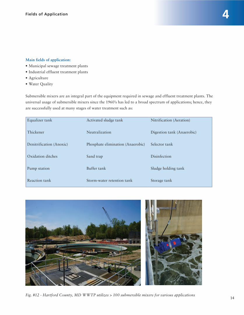
Main fields of application:
•Municipalsewagetreatmentplants
•Industrialeffluenttreatmentplants
•Agriculture
•WaterQuality
Submersible mixers are an integral part of the equipment required in sewage and effluent treatment plants. The
universal usage of submersible mixers since the 1960’s has led to a broad spectrum of applications; hence, they
are successfully used at many stages of water treatment such as:
Equalizer tank Activated sludge tank Nitrification (Aeration)
Thickener Neutralization Digestion tank (Anaerobic)
Denitrification (Anoxic) Phosphate elimination (Anaerobic) Selector tank
Oxidation ditches Sand trap Disinfection
Pump station Buffer tank Sludge holding tank
Reaction tank Storm-water retention tank Storage tank
Fig. #12 - Hartford County, MD WWTP utilizes > 100 submersible mixers for various applications

15
4 Fields of Application
The essential submersible mixer
tasks can be described as follows:
1. Sludge Agitation
Suspending or re-suspending
viscous media
Sludges produced in process
engineering are made for further
use. For example Bentonite
(drilling mud) is needed for
sealing soils during drilling, or
lime milk is used for conditioning
sewage sludges. On the other
hand sludges are often just waste
products which must be disposed
of.
For further sludge treatment, it is
necessary to turn them into
pumpable mixtures of
homogenous consistency. If they
are thickened for later transport
it is important that the sludges
that are fed to the dewatering
equipment (e.g. centrifuge, belt
filter or chamber filter press), be
well mixed. A homogenous
consistency is also required for
municipal sludge used in
agriculture land application.
2. Flow Generation
Maintaining certain flow
conditions and/or pre-defined
flow velocities. (Suspending
solids and sludge flocculants in
water)
Enhanced Nutrient Removals
(ENR) of Phosphate and
Nitrogen are ever important
technologies in sewage or effluent
treatment systems. Generating
and maintaining the flow
conditions required by the
biological process is vital in the
anoxic, anaerobic and aerobic
treatment stages utilized for
ENR. In sewage and effluent
treatment plants, submersible
motor mixers are preferably used
to produce these flows.
Pratical Application:
The practical application of
submersible mixers in the flow
reactor (tank, reservoir, channels,
ponds, aeration system, etc.)
requires an exact knowledge of
the effects of flow restrictions to
be expected, both in terms of
quantity and quality, as well as of
the fluid mechanics. All of the
three elements, the reactor, the
mixer and the medium create one
interactive system. A typical
design goal is to effectively mix
the system while utilizing
minimum power. Assuming one
parameter, the medium for
instance, is constant then only
the remaining parameters can be
modified to increase efficiency.
However more commonly both
the medium and the reactor
cannot be altered, therefore the
mixing efficiency is driven solely
by the mixer selection. In these
situations the submersible mixer
provides the most flexibility /
options to optimize the system.

5Mixer Sizing
Mixer Sizing:
All processes that utilize mixers
have a specific mixing result
that needs to be achieved.
Typically desired mixing results
are complete suspension of
activated sludge or a certain
cross-sectional mean flow
velocity. The energy density
(power per tank volume)
necessary to acquire such
mixing result can serve as an
extremely valuable evaluation
criterion. This evaluation
criteria is supported by the
wastewater industry standard
mixing document VDMA
24656 : 2010-03.
Energy Density = P1 / V
P1 = electrical power (W) from
the electrical system at the
operating point (wire to water
power)
V = tank volume (ft³)
However energy density varies
greatly from tank to tank and
among various mixer designs.
Therefore it is valuable to know
how to calculate the power of
mixers and the parameters
involved in the mixing process
itself. The key to mixer
performance is that with
constant flow velocity
(equilibrium) the forces involved
in the mixing process are the
determining factor. Therefore forces or
thrusts, which are independent of power,
are the necessary method for mixer
sizing. For further details of the
hydraulics required to reach equilibrium,
see “Flow Build-Up” section 6.
Thrust Freq. = F1 + F2 + F3+ F4 + ......
Freq. - required thrust (maintaining the
balancing conditions for a defined
velocity)
F1 - internal friction in the fluid
(turbulent movement in the fluid,
jet stream vs. bulk flow)
F2 - external friction on the
wetted areas (floor, walls, obstructive
installations)
F3 - forces resulting from geometry losses
(tank shapes, deflectors, obstructive
installations etc.)
[fig #13]
F4 - forces resulting from flow streams
(inlets/outlets, air supply during aeration
etc.)
Strictly speaking, the forces F3
and F4 belong to the internal and
external frictions F1 and F2 as these
losses mainly derive from flow
separation and are caused by turbulent
flows. Due to the interference effects, the
total flow loss of the resistances in series
is not equal to the sum of the individual
resistances.
16

17
5 Mixer Sizing
Fig. #13 - Example of turbulent flow from obstructive installations
Fig. #14 - Thrust measurement
apparatus for testing per ISO 21630
The calculated required thrust is compared with the available thrust of the mixers and provides the required size and
number of mixers to be used. Once the mixers are selected on a basis of thrust, then power requirement can be
determined because the mixers‘ input power (P1) at the operating point (given thrust) is known via factory testing as
shown in figure #14. This factory testing is done in accordance with the relatively new ISO 21630 standards released
in 2007. Note that there is no direct correlation or simple calculation to compare thrust to power; therefore it is not
appropriate to size or compare mixers on a power basis!

The aim of KSB development efforts is to
find favorable solutions in terms of
energy consumption. Improving the
propeller efficiency leads to a reduction
of the energy density. If the energy
density is specified, it will actually
impede technically favorable
developments! This also applies to the
closely related average velocity gradient
(G), which is discussed in the Metcalf &
Eddy Wastewater Engineering Treatment
and Reuse handbook.
18
5Mixer Sizing
The last factor to be calculated is the
energy density which can be used to
compare different mixer makes,
models, and technologies. Therefore
energy density is a great tool for
evaluating various solutions for a
specific application, however be
careful because the specification of a
pre-determined energy density will not
lead to correct results!
The energy density is influenced by
the:
•tank geometry
•tank volume
•obstructions
•inlets / outlets
•aeration
•propeller diameter
•propeller speed
•propeller hydraulic design
•motor efficiency

19
6 Flow Build-up
Flow Build-up:
After the mixer has started-up and reached operating thrust, the flow will slowly build-up as illustrated
below in figure #15 until it has reached the equilibrium conditions (average flow velocity).
Fig. #15 - Flow Build-Up
The propeller‘s capacity depends on the propeller diameter, the speed and its hydraulic characteristics.
The developing flow (jet stream) which comes in contact with the propeller‘s rotation becomes a far-
reaching spiral-type jet stream as shown in below figure #16. A shearing stress takes place along this outer
edge of the jet flow; which is the friction between jet stream flow and the slower moving liquid to be mixed
outside of the jet stream.
Fig. #16 - Jet Stream

20
6Flow Build-up
Intensive mixing is achieved when the jet flow comprises the entire tank volume and induces a bulk flow
(channel flow). The bulk flow is subjected to swirls induced by the propeller, but certain geometry
dependent fluid dynamics (flow mechanics) will develop in every tank. Typical features are demonstrated
below (fig. #17) in a “racetrack” type tank equipped with a partition.
Fig. #17 - Flow deviations in a racetrack
The swirl-type flow interferes with the bulk flow (channel flow) in the cross-sectional area of the
partition. The straight channel flow hits the tank wall in the curve, decelerates and is directed to the floor
so that a curved spiral flow develops in the cross-section.

21
6 Flow Build-up
Furthermore a flow separation develops behind the partition and displays itself as a relatively stationary
flow obstruction to the main flow. The reduced cross-section - due to this separation of flow - accounts for
the majority of the losses with this particular geometry.
The build-up of the flow is terminated as soon as the equilibrium conditions have been reached (fig. #18).
This is achieved when all forces impeding the build-up of flow are effective and there is no further increase
of the bulk flow. It is this equilibrium condition that is most often desired in wastewater applications.
Fig. #18 - Equilibrium Flow Forces
Equilibrium conditions are:
Total propeller thrust = Total reaction thrust

One should not mistake the theoretical circulation time for the
effective mixing time. The actually required mixing time depends on
the medium to be mixed and its rheological characteristics.
As the rheological characteristics are usually not known, the
circulation time is approximately taken as the mixing time.
Fig. #19 – Typical Oxidation Ditch (Malatya Turkey)
Furthermore proper mixer quantity and positioning is critical to
ensure that total tank volume is actually circulated, such that flow
paths are not short circuited. Not all fluid must directly move through
the mixer in order to gain velocity. For more detailed information see
further discussion in “Flow Guidance – Mixer Positioning” section
11.
22
7Theoretical Circulation Time
Theoretical Circulation Time:
In many applications the
circulation time is of interest to
the designer. For example it is
common to evaluate the
circulation time in extended
aeration oxidation ditches (fig.
#19). The theoretical circulation
time is the quotient of the tank
volume and the mixer‘s flow
rate. This value gives the
theoretical time it takes for the
mixer to circulate the complete
contents of the tank one time.
V tank
t circulation =
Q mixer
t circulation (s)
V tank (ft3)
Qmixer (ft3/s)
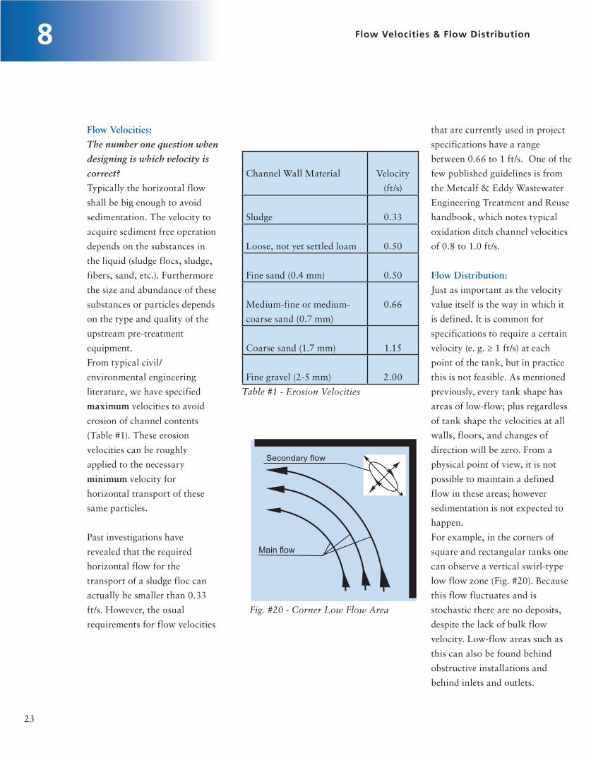
Channel Wall Material Velocity
(ft/s)
Sludge 0.33
Loose, not yet settled loam 0.50
Fine sand (0.4 mm) 0.50
Medium-fine or medium-
coarse sand (0.7 mm)
0.66
Coarse sand (1.7 mm) 1.15
Fine gravel (2-5 mm) 2.00
Table #1 - Erosion Velocities
Fig. #20 - Corner Low Flow Area
23
8 Flow Velocities & Flow Distribution
Flow Velocities:
The number one question when
designing is which velocity is
correct?
Typically the horizontal flow
shall be big enough to avoid
sedimentation. The velocity to
acquire sediment free operation
depends on the substances in
the liquid (sludge flocs, sludge,
fibers, sand, etc.). Furthermore
the size and abundance of these
substances or particles depends
on the type and quality of the
upstream pre-treatment
equipment.
From typical civil/
environmental engineering
literature, we have specified
maximum velocities to avoid
erosion of channel contents
(Table #1). These erosion
velocities can be roughly
applied to the necessary
minimum velocity for
horizontal transport of these
same particles.
Past investigations have
revealed that the required
horizontal flow for the
transport of a sludge floc can
actually be smaller than 0.33
ft/s. However, the usual
requirements for flow velocities
that are currently used in project
specifications have a range
between 0.66 to 1 ft/s. One of the
few published guidelines is from
the Metcalf & Eddy Wastewater
Engineering Treatment and Reuse
handbook, which notes typical
oxidation ditch channel velocities
of 0.8 to 1.0 ft/s.
Flow Distribution:
Just as important as the velocity
value itself is the way in which it
is defined. It is common for
specifications to require a certain
velocity (e. g. ≥ 1 ft/s) at each
point of the tank, but in practice
this is not feasible. As mentioned
previously, every tank shape has
areas of low-flow; plus regardless
of tank shape the velocities at all
walls, floors, and changes of
direction will be zero. From a
physical point of view, it is not
possible to maintain a defined
flow in these areas; however
sedimentation is not expected to
happen.
For example, in the corners of
square and rectangular tanks one
can observe a vertical swirl-type
low flow zone (Fig. #20). Because
this flow fluctuates and is
stochastic there are no deposits,
despite the lack of bulk flow
velocity. Low-flow areas such as
this can also be found behind
obstructive installations and
behind inlets and outlets.

8Flow Velocities & Flow Distribution
24
Further complicating the situation is the fact that a simple calculation method capable of providing the
velocity at a certain point in the tank does not exist. In fact, it requires a very time consuming and
expensive computational fluid dynamics (CFD) model simulation to solve this problem. KSB provides such
CFD models for very special tank geometries or as requested by the customer, but typically such detailed
local velocities are not necessary to ensure adequate mixing for the process.
Fig. #21 - Localized CFD Flow Velocities
Therefore in practice a hydraulic calculation of the flow which only takes the tank friction losses into
account is utilized. The limitation of this method is that it only provides a value for the mean flow velocity
in the cross-sectional area. Thus only a mean velocity in the defined cross-section can be ensured. Due to
the complex flow processes, another definition is not feasible.
Special Flow Loss Case - air supply (transverse flows):
In applications with air supply, transverse (vertical) flows with regard to the horizontal mixer flow occur
which influence the flow distribution in the cross-sectional area. Therefore in addition to specifying the
guaranteed mean velocity in aerated tanks, it is also necessary to indicate the square footage of aerated
floor area and associated input air volume (SCFM). Since 100 % air supply is typically required only in the
event of a malfunction or accident, it must be defined for which air supply conditions that the specified
horizontal mean velocity is necessary.

8 Flow Velocities & Flow Distribution
25
For example it seems appropriate to
specify a mean velocity of 1 ft/s without
air supply. However, in the event of a
maximum air supply (malfunction/
accident) a mean horizontal velocity of
0.5-0.66 ft/s should still be available.
The applicable velocities must again be
determined by taking the expected solids
into account. However when combined
with aeration it is also important to
consider typical operating procedure and
how much if any mixing will be
accomplished by the aeration.
Fig. #22 - Schematic of Ring Shaped Test Reactor
Example field test of mixing with aeration:
Ring shaped nitrification/aerobic tank (Fig.#22)
Quantity: 6mixers
Tank Volume: 1.5 million gallons
Channel Depth: 16.5 ft
Max Air Supply: 7,770 SCFM
Propeller ∅: 8.2 ft
Power (P1): 4.7 hp
Energy Density: 0.10 W/ft3
The flow measurement was carried out at three different
air supply rates (0, 50, & 100% of max air supply). The
change of the flow distribution is displayed in the
following diagrams (fig. #23). Note that as air supply
increases the horizontal velocity becomes more constant
across the tank depth, however the losses from transverse
flow cause the average horizontal velocity to decrease.

26
8Flow Velocities & Flow Distribution
Fig. #23 - Velocity Results (0%, 50%, & 100% air supply)

27
9 Submersible Mixer with Bottom Diffusers
Mixing with Diffusers:
Previous section 8 touched on mixing
combined with aeration as shown in
adjacent figure #24. This topic will be
focused in this section, since this is an
increasingly common application, in
activated sludge tanks (nitrification,
SBR, etc.). In particular the
correlation between horizontal flow
generated by the submersible mixer
and vertical flow induced by the
supply of air shall be explained.
Physical fundamentals:
•Withouttheinfluenceofexternal
forces an air or gas bubble can only
rise vertically in a liquid
•Withouttheinfluenceofexternal
forces a swarm of bubbles can only
rise vertically in a liquid
•Dependingontheirdirection,
existing vertical flows (forces) have a
positive or negative influence on the
upward velocity of the gas bubbles (i.
e. flow directed downwards towards
the tank floor will reduce the velocity
while the flow directed upwards
towards the surface will increase the
velocity).
•Existinghorizontalflows(forces)do
not have any influence on the upwards
velocity of the gas bubbles
•Flowsarevectors
Fig. #24 - Combined Mixing & Aeration
Looking at individual bubbles reveals that a bubble
corresponding to its expansion has a defined uplift and rises to
the surface with the corresponding velocity.
Fig. #25– Aeration without Horizontal Flow
The above figure #25 shows bubbles that are injected into the
liquid at equal time intervals as they rise to the surface.

28
9Submersible Mixer with Bottom Diffusers
S => Path the air travels in ft
vair => Uplift velocity in ft/s
t => Travel time in s
If a horizontal flow is present in the same system, the bubble travel time should not change according to
the physical fundamentals. The following figure #26 shows a horizontal laminar flow with bubbles
injected at equal time intervals as they rise to the surface. If the moving liquid is evaluated in volume
segments per unit of time, it can easily be recognized that the bubbles in the corresponding segment rise
vertically to the surface at the standard upward velocity (vair).
Fig. #26 – Aeration with Horizontal Flow
At the same time it can be see that the bubbles follow a diagonal movement along the resultant of upward
bubble velocity and horizontal flow. However vertical path and thus time the bubble takes to rise to the
surface is the same as in figure #25.
However in real world practical applications turbulent flows are present. Therefore the above
consideration with a laminar flow is only a theoretical representation to show that the horizontal flow has
no simple influence on the air/liquid contact time. Based on these finding the following question is raised:
Q: Is there any advantage from a process technology point of view by adding horizontal flows?
A1: Solids and sludge can be kept in suspension with the minimum process required air input.
A2: The bacteria are supplied with the new substrate.
A3: In practice the bubble travel time is actually longer.
Answers A1 and A2 are self-explanatory and shall not be further discussed. On the other hand answer A3
is in contradiction with the previous laminar flow based discussion; thus it must be further evaluated.

9 Submersible Mixer with Bottom Diffusers
29
In practical applications, the
individual bubble must be
evaluated in conjunction with the
turbulent swarm of bubbles and
associated generation of water
flow. This resulting turbulent
water-air-mixture flow creates
visual proof in the form of a
swell at the water’s surface as can
be seen in the following figure
#27. This liquid is moved to the
surface along with the rising air
and equivalent liquid flow is
sucked up from the bottom of the
tank. The following figure #28
shows how a swirl-type flow is
present on all sides of the
aeration, which makes the air
rise to the surface faster. These
swirl-type flows can double that
of the individual bubbles upward
velocity, reaching about 2 ft/s.
Fig. #27 - Aeration Swarming Affect
Fig. #28 - Aeration Swarming Affect

30
9Submersible Mixer with Bottom Diffusers
Uplift velocity of the air 1 ft/s
+ Flow velocity of the swarming swirl -type flow 1 ft/s
= Total velocity 2 ft/s
Fig. #29 – Combined swarming and uplift effect
The travel time of the bubbles is therefore significantly reduced by the swarming effect. This is a direct result of
the inverse relationship between travel time and total upward velocity.
Now if a horizontal flow is added to these fluid mechanics (fig. #30), the shape of the swirl-type flow will
change. Or in the ideal case, swirl type flow will be completely neutralized and fluid dynamic conditions will
arise which are similar to those of laminar flows.
Vair
Vliquid
VTotal
Fig. #30 – Addition of horizontal flow to aeration
The horizontal flow causes the turbulent bubble swarm to drift away with the flow. On the front, the
swirl-type flow is neutralized or nearly neutralized. On the rear side, it is still there, however the
horizontal bulk flow changes the shape and reduces the vertical velocity.
In summary the contact time of the bubbles is increased through the reduction of the vertical swirl
flow! Because of this increased contact time, already efficient diffusers can provide even higher oxygen
transfer rates to reduce operational costs. Furthermore because the mixing and aeration systems are
completely independent, the energy intensive compressors can be turned down to provide only the
aeration required for the biological process.
↑↑
Horizontal Flow
∧Aeration/Mixng Flows are vectors:
Therefore as depicted in below Fig. #29 the swirl flow has a postive influence and can be added to the air
lift velocity.

31
10 Transportation of Solids in Activated Sludge
Solids Transport:
An extensive separation of
solids is required to optimize
sewage treatment plants. The
quality of the equipment
installed upstream of the tanks
determines the type, shape,
quality and particle size of the
solids in the system. If a typical
velocity of 1 ft/s is specified for
the mixers, it means that not
only sludge flocs but also non-
volatile solids have to be moved.
The medium flow through the
different treatment stages must
ensure that solids are
transported to avoid the
buildup of sedimentation. This
may be accomplished by
physical tank design to guide
the flow through the tanks and
mechanical agitation/guidance
via submersible mixers.
Solids transportation cannot be
defined solely by velocity; the
guidance of the solids in the
system is also highly important.
Furthermore the velocity
needed for a sediment-free
operation (where possible)
should be determined by the
solids entering the tank and
past experience were possible.
By holding back/removing the
solids at the headworks and
optimizing the flow for
biological purposes it is possible
to reduce the velocity and,
consequently, the required
the outlet. This means that the
solids must be deliberately
transported to the outlet.
However keep in mind that
heavier particles such as sand
cannot be lifted with the typical
mixer generated bulk flow
velocities of around 1 ft/s. This
should be no surprise if you
consider that typical design
guidelines for vertical sewage
pipes require much greater
velocities in the range of 6 to 8
ft/s.
Following are some examples of
how to achieve such solids
guidance.
energy density of the mixing
equipment. As can be seen by the
table on page 23 the necessary
velocity varies greatly depending
on solids type.
As previously discussed, when
there is no local turbulence
sludge flocs can be mixed at a
velocity of less than 0.33 ft/s.
However for sizing the mixer the
non-volatile solids are typically
taken into account and a safe
mean velocity of 1 ft/s in the
cross-sectional flow area is
assumed so that the power
required to generate the flow can
be calculated. The alignment of
the submersible mixers which
vary depending on the tank
geometry, outlet and
installations/structures in the
tank is considerably responsible
for the distribution of the flow in
the cross-sectional area.
A strictly horizontal flow does
not have any advantages for the
distribution of the solids in the
tank. The horizontal movement
does begin suspension by putting
the solids in horizontal motion;
however specifically heavy
particles move around close to
the floor and specifically light
particles are distributed in the
entire cross-sectional area.
Simply put; in order for solids to
leave the tank, they must reach

Example: Flow through cascades arranged in series
Fig. #31 – Cascades with overflow weir
Cascades which are designed such that the flow passes over an overflow structure, as illustrated in above
figure #31, need flow guidance ensuring the solids are transported up to the overflow. Using a defined
horizontal velocity, solids of a certain size, shape and density are moved, however, not lifted to the surface
which means that in the long run a concentration of the specifically heavy solids takes place and
sedimentation is to be expected. For further detail see following “Special Concerns” portion of this
section.
Fig. #32 – Cascades with underflow wier
Alternatively if the tank flow path is changed as shown in above figure #32 - underflow wier, then the
solids are effectively transported by through flow.
Example: Flow in Round tank In order to remove solids it is possible to transport them to the middle of
the tank through the use of submersible mixers creating a circular type flow (tea cup effect). In the case of
a circular flow, the strongest flow takes effect around the outside of the tank, and weakens closer to the
center, ceasing entirely at the center of the flow’s rotation. Also the circulation in the tank is decelerated by
the tank wall, resulting in the creation of a swirl-type flow which interferes with the circulatory
movement. On the tank wall, this interfering flow is directed towards the floor and then to the center of
the floor. In the tank center (axis of the circular flow), the velocity is zero and the swirl-type flow in an
upwards direction is too low to lift the solids to the surface. These hydraulic phenomena are depicted in
figure #33. Therefore tank drain/suction shall be placed at the center of the tank in order to remove solids.
32
10 Transportation of Solids in Activated Sludge
Under flow Under flow

33
10 Transportation of Solids in Activated Sludge
Sediments
Solids which are carried to the center by the
flow cannot move away from there
Fig. #33 – Hydraulics of round tank
Many times round tanks with center drain are routinely emptied or run at low water levels. In these cases
submersible high speed mixers should be utilized to allow maximum run time during draw down. A
recommended minimum water level will be provided by manufacturer, which gives minimum operating
level for optimum mixing performance without vortex formation. However mixer operation (for propeller
diameters < 24 in.) below this level is acceptable as long as the motor remains submerged.
Taking the tank geometry, the flow pattern and the solids transportation into account, a favorable tank
drain can be designed to ensure the hydraulic transportation of solids out of the tank.
Special concerns regarding tanks with overflow weir outlet
When the outlet is arranged close to the surface (i.e. on overflows or outlet channels of pre-treatment tanks
that have been retrofitted for de-nitrification), a vertical flow higher than the sinking velocity of the
particles is absolutely necessary for the solids transportation (i.e. solids must be forced upwards). With
special care this can be achieved with the use of submersible mixers (figure #34).
Fig. #34 – Solids guidance with overflow weir

34
10Transportation of Solids in Activated Sludge
It takes special care, because
when the jet flow of the
submersible motor mixer is not
exactly directed to the overflow,
the solids (i. e. more specifically
the heavier solids) cannot be
made to flow over the overflow
structure. The result is a
concentration of specifically
heavier solids in the tank. This
occurs because the solids are
horizontally moved by the flow
until a concentration has been
reached for which the flow
velocity (energy) is no longer
sufficient.
The time it takes for sediments
to form is directly dependent on
the amount of specifically
heavier particles reaching the
tank. It may take one to two
years or even longer for the
deposits to develop in low-flow
areas. Eventually tanks will
need to be cleaned, which
typically requires tank
draining.
For optimum solutions it is highly
recommended that there be design
co-operation with a competent
manufacturer of submersible motor
mixers.

Fig. #35 – Propeller Hydraulics
General Positioning Considerations
Generally speaking, the flow jet stream (impetus) should start from a
hydraulically optimal position (position varies according to tank
geometry). Therefore with each KSB quote a mixer positioning sketch is
provided to show the optimal position. Optimal positioning facilitates
the smooth running of the mixer in order to prolong its service life. At
the same time, the operational efficiency of the mixing system will
increase via a low energy density.
KSB verifies all results and positioning guidelines via a combination of
computational fluid dynamics modeling and field verifications. When
positioning the mixer, negative effects on the propeller discharge and
suction sides must be minimized. Sample interference can include:
On the suction side: On the discharge side:
Flow stream from inlets and
outlets
Disturbance of flow build-up
Turbulent flows resulting from
obstructive installation
Obstructions directly in front of
the propeller
Extra air in the area of the
propeller
11 Flow Guidance and Mixer Positioning
35
Propeller Hydraulics:
As discussed in section 6 the
mixers capacity highly depends
on the propeller diameter, the
speed and its hydraulic
characteristics. Please refer back
to this previous section for
basics regarding propeller
hydraulics.
The running conditions of the
mixer are also highly dependent
on the hydraulic condition of
the tank. The propeller capacity
itself is constant and typically
bigger than the inlet flow
provided to the mixer. Since the
fluid is not constrained near the
mixer it will flow the way of
least resistance; therefore as
shown in figure #35 the
propeller will draw in the local
fluid and create a back flow
(short circuit flow) to the
propeller.
Tank shapes with higher loses
will have an increasing amount
of back flow. This is because
the back flow is directly related
to the losses imparted by the
total hydraulic condition of the
tank. Thus a reduction of the
back flow is only possible by
decreasing the flow losses
encountered by the mixer. This
can be accomplished by
modifying tank obstruction
and/or slowing the mixer speed
to reduce internal friction
forces.

11Flow Guidance and Mixer Positioning
36
In general negative influences on the suction side of the propeller impair its ability to run smoothly, and on the
discharge side increase energy density.
General Tankage Considerations
For process success the tank design is as equally important as the mixer hydraulics and positioning. In particular the
following data clearly shows that tank shape can highly affect thrust, creating over 350% variation. Since thrust is
related to the required mixer power/size; tank selection will directly impact the capital and/or operational cost of the
mechanical equipment.
Tank Shape Volume Approx. Needed Thrust Dimensions Thrust Factor
Round 150,000 ft3 170 lbf 1.00
Ring channel 150,000 ft3 150 lbf 0.88
Rectangular 150,000 ft3 220 lbf 1.29
Racetrack without guide bends 150,000 ft3 530 lbf 3.12
Racetrack with short guide bends 150,000 ft3 250 lbf 1.47
Racetrack with long guide bends 150,000 ft3 220 lbf 1.29
Round Tanks
In relation to other shapes, round tanks are inexpensive to manufacture. However cost increase when multiple tanks are
required because common wall construction cannot be utilized and there is a larger land space requirement. They also
produce a low amount of tank geometry-related losses. This means that low energy density for mixing can be reached
in these tanks given the same volumes. The flow distribution is problematic though, as incorrect positioning of the
mixer can easily lead to the generation of unwanted flow patterns. The desired flow pattern must be defined based on
the results required.
Possible results:
1. To remove solids from the tank (e. g. the cleaning of storm-water tanks)
2. To hold solids in movement (suspension) (e. g. activated sludge tank, sludge silos etc.)
*Standard activated sludge tank geometries of equal volume being mixed to achieve average blulk flow velocity of 1 ft/s.

37
11 Flow Guidance and Mixer Positioning
1. Removing solids from the tank
In order to remove solids it is possible to transport them to the middle of the tank through the use of a circular
jet flow (tea cup effect). If fluid is drained out of the tank from the middle, then the solids will be removed. This
effect finds use in the cleaning of rainwater and sludge tanks, in which mixers establish and maintain a circular
jet flow. This means that before the tank is emptied the solids have been removed, and if the level sinks low
enough, the mixing machinery will surface.
2. Holding solids in motion (suspension)
Solids should be moved by the jet flow
and transported with the fluid. The
difficulty of suspending solids increases
with falling levels of viscosity in the fluid
medium, and increasing solid densities
(i.e. coarse sand laden water). This means
that the sedimentation behaviors, or more
precisely the fluid characteristics, are an
important factor for the level of flow
velocity required in order to keep the
solids in suspension.
Circular (tea cup effect) flows like those
mentioned above are not suitable and
must be avoided.
This is made possible through following
positioning guidelines:
The positioning of the submersible mixer
in the tank
In order to avoid a circular flow (tea cup
effect), the flow impetus is orientated
towards the middle of the tank, thereby
creating a stronger jet flow in this area
which acts to prevent sedimentation in the
center of the tank.
Fig. #36 – Round Tank Positioning for Solids
Suspension
Floor/Bridge Mount
Wall Mount

behind the mixer. However when correctly sized and positioned the
turbulence created by a submersible mixer is sufficient to keep all
solids in suspension. Typically sedimentation in ring channels is
because of insufficient number of mixers. See below figure #37 for
examples.
This arrangement of the mixers is
also dependent on its accessibility
via bridges.
Installation of the mixer in
relation to the tank wall
The operation of submersible
motor mixers in immediate
proximity to the tank wall is only
possible with fast running
(Amamix) mixers with a small
propeller diameter.
Slow running (Amaprop) mixers
with propeller diameters of 5 to 8
feet and propeller speeds of 15 to
60 rpm require a greater distance
from the tank wall, as
demonstrated in the adjacent
sketches (Fig. #36); meaning
bridges or other means of access
are needed.
Ring Channel:
The fluid mechanics are the same
as with a circular tank, but there
are additional wall surfaces that
depending on dimensions increase
thrust requirements and
associated energy density due to
losses; or reduce thrust and
associated energy density by
helping to guide the flow. The
sedimentation will be at the
intersection of the floor and
center wall structure if there is a
low velocity (horizontal velocity <
particle settle velocity) point
38
11Flow Guidance and Mixer Positioning
Fig. #37 - Ring Channel Sedimentation
Insufficient Mixing Sufficient Mixing
Flow Seperation
Sedimentation

39
11 Flow Guidance and Mixer Positioning
Rectangular
In relation to other shapes, rectangular tanks can offer a
large capital cost advantage when multiple tanks are
required. This is typically because of shared wall and
walkway design as well as reduction of land space
requirements.
However as a result the rectangular tank design does
sacrifice approximately 30% in mixing efficiency. The loss
in mixing efficiency is primarily a result of corner vortices
as can be seen in the adjacent figure #38.
It should be noted that even though these vortices act as a
flow obstruction, there is random localized movement of
the vortex that provides for deposit free operation. The
complexity of the tank/mixer effects means that the
designer must work with mixer manufacturer to evaluate
the best overall solution on a case by case basis.
Racetrack:
The channel flow of a racetrack provides the same effects
at the floor and water surface as with the circular tanks
and ring channels.
However largely in contrast to the circular tanks and ring
channels, the flow behind the middle wall is obstructed by
a flow separation (fig. #39). This flow separation is a quite
large vortex resulting in a reduction of the flow area
which creates additional flow losses. The additional losses
can result in more than 3 times the mixing thrust as
required for a round tank of similar volume.
Fig. #39 – Racetrack Flow Separation
Fig. #38 – Retangular Tank Corner Vortices

40
11Flow Guidance and Mixer Positioning
However the mixing energy density in racetrack tanks can be greatly improved by the addition of guide vanes.
These guide vanes located at the bend help to direct flow around the tight turn and minimize the flow
obstructing vortex. Long guide bends, which extend at least one channel width along the downstream side of
the channel, can reduce the necessary mixer thrust by more than 50%. See below figure #40 for a schematic
representation of “normal” guide bend on the left and CFD analysis vector results for a “long” guide bend on
the right.
Fig. #40 – Racetrack’s with Guide Bend
Special Case – Installation Limits for Long Tanks
Rectangular type tanks:
Fluid mechanic limitations for single mixer are illustrated in figure #41. Note that for tanks with length
width ratio greater than 2.5 the bulk flow is short-circuited and a low flow area is created at the end of
the tank. However by adding additional units the mixers work in series to create good bulk flow
throughout the tank. This is illustrated in figure #42, which shows how the large green arrowed bulk
flow is generated instead of the typical short circuited flow shown by the red arrows.

41
11 Flow Guidance and Mixer Positioning
Circular ring tanks or long curved rectangular tanks:
The fluid mechanics are the same in regard to the length-width ratio of rectangular tanks although the
bend does have added negative effect. The flow impetus from the submersible mixer travels only in a
straight direction, i. e. along the mixer‘s axis; therefore the flow will always hit the opposite wall when
the tank is considerably curved. To a certain extent, this can be compensated for by positioning the
mixer(s) such that it is directed towards the inside wall space. See following figures for example of poor
mixing (fig. #43) created by insufficient number of mixers and the good mixing (fig. #44) created by the
addition of another mixer.
Fig. #41 - Long Tank Installation Limits Fig. #42 - Long Tank Mixers in Series

42
11Flow Guidance and Mixer Positioning
Fig. #43 - Poor mixing in long tank
Fig. #44 - Good mixing in long tank
43
11 Flow Guidance and Mixer Positioning
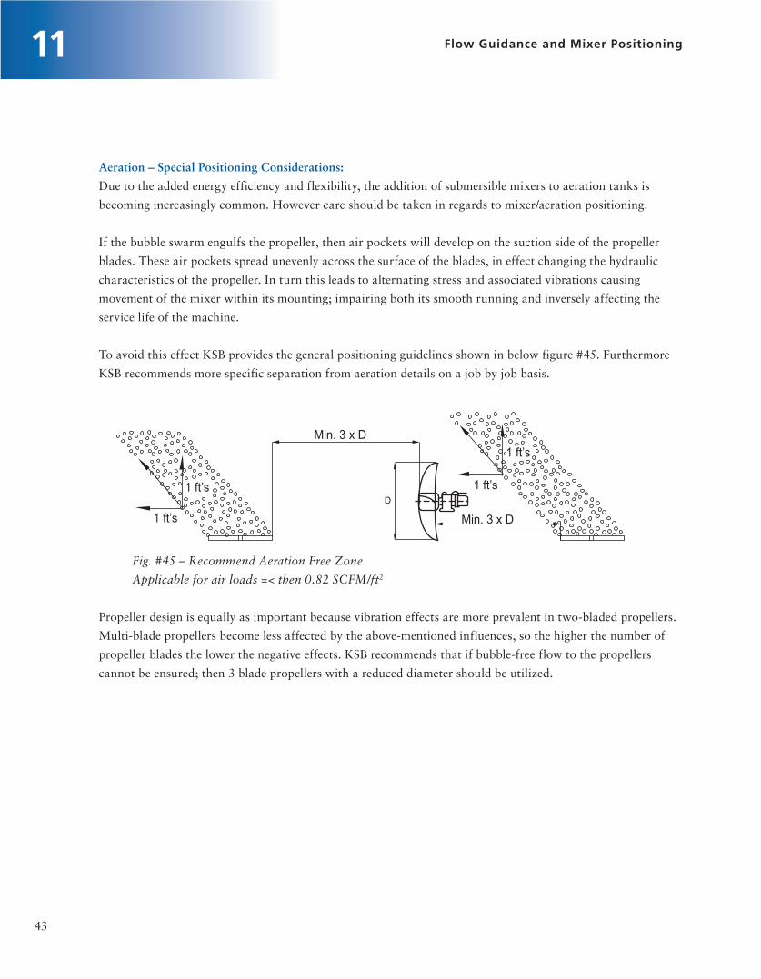
Aeration – Special Positioning Considerations:
Due to the added energy efficiency and flexibility, the addition of submersible mixers to aeration tanks is
becoming increasingly common. However care should be taken in regards to mixer/aeration positioning.
If the bubble swarm engulfs the propeller, then air pockets will develop on the suction side of the propeller
blades. These air pockets spread unevenly across the surface of the blades, in effect changing the hydraulic
characteristics of the propeller. In turn this leads to alternating stress and associated vibrations causing
movement of the mixer within its mounting; impairing both its smooth running and inversely affecting the
service life of the machine.
To avoid this effect KSB provides the general positioning guidelines shown in below figure #45. Furthermore
KSB recommends more specific separation from aeration details on a job by job basis.
Fig. #45 – Recommend Aeration Free Zone
Applicable for air loads =< then 0.82 SCFM/ft2
Propeller design is equally as important because vibration effects are more prevalent in two-bladed propellers.
Multi-blade propellers become less affected by the above-mentioned influences, so the higher the number of
propeller blades the lower the negative effects. KSB recommends that if bubble-free flow to the propellers
cannot be ensured; then 3 blade propellers with a reduced diameter should be utilized.

44
12Typical Submersible Mixer Sizing Information & RFQ Sheet
Sizing Information:
Throughout this document we have stressed the importance of working closely with a competent
manufacturer to select the best mixer for a given application. The particular details and methods oriented
with submersible selections are covered in the “Mixer Sizing” section 5 of this document. In that section it is
also made clear that the energy density is not a good tool for mixer sizing. However with the better
understanding provided by this document it is possible to use some “typical” energy density values for
planning purposes. Therefore you will find below a table of typical energy densities for KSB submersible
mixers. Please be sure to consider the associated notes when utilizing these values. Also be sure to note that
the table clearly shows trends such as the inverse relationship between tank volume and energy density.
Notes / Assumptions:
•Concretetankwalls
•Noaerationconsidered.Typicallyaerationwillincreaseenergydensitybyatleast5%
•TypicalactivatedsludgemediumwithTSS<1%
•Designcriteriaisaveragevelocityof1ft/s
•Racetrack(oxidationditch)assumedtohavelong(extenddownstream)guidebends

45
12 Typical Submersible Mixer Sizing Information & RFQ Sheet

46
13
References
1. International Organization for Standardization, Pumps – Testing – Submersible mixers for
wastewater and similar applications, ISO 21630, 2007
2. Verband Deutscher Maschinen und Anlagenbau, Agitators in activated sludge tanks of wastewater
treatment plants – Information on planning, project design and construction, VDMA 24656, 2010
3. Metcalf & Eddy, Inc., George Tchobanoglous, Franklin L Burton, H. David Stensel, Wastewater
Engineering Treatment and Reuse 4th Edition, 2003
4. Fred Koch, KSB Fluid Mixing Manual, 2001
Photographs
All of the photographs for this booklet were taken by KSB or its representatives, unless otherwise noted.
Contributing Authors
Jared S. Wray, P.E., born in 1982 studied Mechanical Engineering at the University of Delaware. After
completing his studies, he became a design engineer for an independent consulting firm. Since 2008 he
has been employed by KSB, Inc. and held positions in both the Energy and Wastewater divisions. Since
2011 he holds position of Product Manager for Submerged Propeller Devices in the USA.
Thomas Koch, born in 1972 studied Civil Engineering and majored in water and sewage management at
the University of Applied Science in Suderburg. Since 2001 he has been employed by KSB
Aktiengesellschaft as the mixer expert. Since 2010 he holds position of Head of Product Management
Submerged Propeller Devices.
Fred Koch, studied Mechanical Engineering. Throughout his career he worked for Pendraulik, Flygt,
and EMU. In 2001 he was employed by KSB as the Head of Product & Application for mixers. Mr.
Koch retired from KSB in 2008.

KSB, Inc.4415 Sarellen RoadHenrico, VA 23231www.ksbusa.com
Your local KSB representative:
153
93.0
222
/ 05.
13 /
© K
SB, I
nc.
201
3
Technology that makes its mark