submittal requirements for design documents l.pdf · submittal requirements for design documents...
TRANSCRIPT
APPENDIX L
Owner‟s Design Guidelines 10/1/10 Page 1
SUBMITTAL REQUIREMENTS FOR DESIGN DOCUMENTS
TABLE OF CONTENTS
A. PENDING ISSUES REPORT .......................................................................................2
B. CONSTRUCTION COST ESTIMATE .........................................................................2
C. SCHEMATIC DESIGN DOCUMENTS ......................................................................2
1. Civil............................................................................................................................3
2. Architectural ..............................................................................................................3
3. Structural ....................................................................................................................4
4. Mechanical .................................................................................................................4
5. Electrical ....................................................................................................................5
6. Landscape Architectural ............................................................................................5
D. DESIGN DEVELOPMENT DOCUMENTS ...............................................................6
1. Civil............................................................................................................................6
2. Architectural ..............................................................................................................6
3. Structural ....................................................................................................................8
4. Mechanical .................................................................................................................8
5. Electrical ..................................................................................................................11
6. Landscape Architectural ..........................................................................................12
E. CONSTRUCTION DOCUMENTS .............................................................................13
ATTACHMENT A - Pending Issues Report Example…………………………….…….16
ATTACHMENT B – Basic Data……………………………………….………………..17
ATTACHMENT C – Cost Quantity Survey Example...……………….………………...19
APPENDIX L
Owner‟s Design Guidelines 10/1/10 Page 2
SUBMITTAL REQUIREMENT FOR DESIGN DOCUMENTS
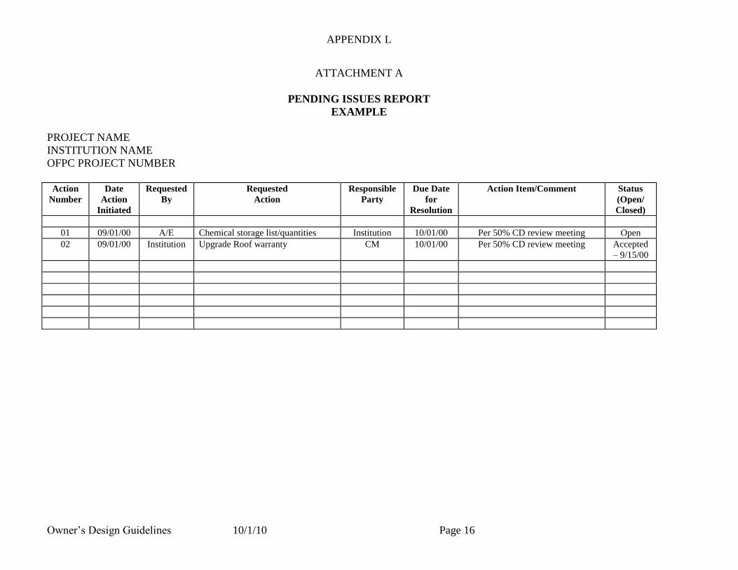
A. PENDING ISSUES REPORT
The Project Architect/Engineer shall prepare and maintain a Pending Issues Report
throughout the Schematic Design, Design Development and Construction Document
Phases to record outstanding decisions for the Design Team. An example may be seen as
Attachment A, Pending Issues Report. The example indicates the kinds of data that
should be maintained and documented for pending issues.
B. CONSTRUCTION COST ESTIMATE
The Project Architect/Engineer shall provide a Construction Cost Estimate by an
independent estimating company, acceptable to the Owner, throughout the entire design
process at the end of each design phase (or as necessary to meet the Owner‟s identified
Construction Cost Limitation) until 100% completion of the Construction Documents.
An example may be seen as Attachment C.
C. SCHEMATIC DESIGN DOCUMENTS
The preliminary phase of design services to produce a diagrammatic representation of the
project, including sketches of building exterior and selected interior spaces, outline-level
specification of materials and finishes to be incorporated, general floor plans, and a
narrative assessment (for the non-professional Owner) of proposed building systems.
The design shall be generated from the approved Facility Program, and resulting
conceptual studies and alternative schemes developed in conference with the Owner.
Schematic documents shall be considered “complete” when all areas of design (i.e. Civil,
Architectural, Structural, and MEP) are 100% schematic in nature as defined below and
agreed upon by the Owner.
The submittal requirements noted in this appendix do not exclude elements which
may be unique to a particular project required for the facility design, that are not
specifically identified/mentioned herein or in any of the referenced appendices in the
Design Guidelines. It is the Architect/Engineer‟s responsibility to incorporate any
necessary plans, sections or details in the design documents of each submittal
package for review.
Complete schematic design documents are a result of a completed product and are not
a function of time/duration of work.
Documents that are “on average” 100% schematic will not be considered “complete”
schematic documents.

APPENDIX L
Owner‟s Design Guidelines 10/1/10 Page 3
1. Civil
See Appendix B for Civil submittal requirements.
2. Architectural
a. A copy of the approved Facility Program.
b. Building Code Analysis: Including, but not limited to, IBC, NFPA-101;
Texas Department of Licensing and Regulation, and A.D.A. Refer to
Appendix C.
c. Site description and conditions.
d. Renovation projects shall include plans of the existing building, building
structural system, and areas requiring demolition.
e. Drawings (small scale and schematic in nature):
(1) Site Plan: schematic project location, building footprint, adjacent
structures, access and proposed site improvements.
(2) For renovation projects, provide schematic demolition plan.
(3) Floor Plans (final agreed scheme) showing room layout, room titles,
gross areas.
(4) Selected critical areas (identified by the Owner) to larger scale.
(5) At least two exterior elevations (final agreed scheme), building
profile section showing floor to floor dimensions, ground floor
elevation to mean sea level (MSL), and primary elevation and other
significant façades (street-facing, loading dock area, adjacent to
recognized neighbor).
(6) At least two perspective renderings in color or a model if
authorized.
f. Descriptive Specifications: Brief narrative description of the proposed
component systems, materials and equipment in the Construction
Specification Institute (CSI) Master Format, current edition.
g. Construction Cost Estimate based upon (at a minimum) square footage
costs for building systems (i.e. foundation, structure, exterior closure, roof,
interior construction, specialties, conveying, MEP systems, etc.) typical
for the building type and location.

APPENDIX L
Owner‟s Design Guidelines 10/1/10 Page 4
3. Structural
See Appendix K for Structural submittal requirements.
4. Mechanical
a. Describe briefly the proposed HVAC system, gross design loads, supply
and return air system, principal piping materials, and fire protection
system.
b. Drawings: (small scale, ⅛” = 1‟- 0” minimum, and schematic in nature).
(1) Site Plan, showing location of existing utility sources and
characteristics, and proposed routing of new utilities to building.
(2) For renovation projects, provide schematic HVAC system
ductwork and air devices and Plumbing domestic water and
sanitary waste piping demolition plans.
(3) HVAC Floor Plans showing equipment layout in mechanical
rooms; building floor plans indicating ductwork in single line
format for Supply Air (SA), Return Air (RA) and Exhaust
Systems; indicate estimated SA, RA and Exhaust airflow rates;
piping mains.
(4) Plumbing fixtures and equipment may be shown on Architectural
Floor Plans.
c. Submit completed preliminary copy of Attachment B, Basic Data.
d. HVAC Controls
(1) Describe the proposed controls sequence of operation for each
system.
(2) For systems with multiple fans or pumps, indicate size of each
relative to full load capacity, and how many operate at a time.
(3) For AHU controls, indicate if economizer cycle and CO2 demand
ventilation sequences will be included.
(4) Describe any required network integration of packaged controls
systems for equipment such as chillers, boilers, computer room
AHUs, etc.

APPENDIX L
Owner‟s Design Guidelines 10/1/10 Page 5
5. Electrical
a. Briefly, describe the proposed normal and emergency electrical power
distribution systems, preliminary design loads, interior and exterior
lighting, fire detection/alarm, telecommunication, audio visual, central
clock and CCTV and security systems. Include any other items relevant to
the project, such as lightning protection, special grounding requirements,
UPS, power quality, hazardous locations, etc.
b. Drawings:
(1) Site Plan, showing location of existing or new utility source,
characteristics and proposed routing of new electrical service to
building. Indicate the provider of the power, utility company,
campus generated, etc.
(2) Typical lighting and power layouts and main distribution gear
locations.
6. Landscape Architectural
a. Describe briefly the scope and character of landscape development, both
hardscape and softscape, including proposed special features such as
fountains, sculpture, etc.
b. Cost estimate of site work.
c. Drawings: Reflect Campus Master Plan and/or Facility Program
requirements.
(1) Show areas (in plan) proposed to be planted and irrigated at a scale
consistent with the Architectural Site Plan.
(2) These may be included on the Architectural Site Plan itself unless
degree of complexity requires separate plan sheet.
(3) Show location of water source for irrigation.
(4) Include major space defining elements such as trees, walls, fences,
etc. to convey overall site design concept.
(5) Include major vehicular and pedestrian circulation patterns.

APPENDIX L
Owner‟s Design Guidelines 10/1/10 Page 6
D. DESIGN DEVELOPMENT DOCUMENTS
The continued development of the project design and detailing, refinement and
confirmation of program requirements and schematic design efforts, and the expansion of
outline specifications that fully describe the nature and intent of the project. The design
is a continuation the Schematic Design documents, and resulting studies, and alternative
schemes developed in conference with the Owner.
Design Documents shall be considered “complete” when all areas of design (i.e. Civil,
Architectural, Structural, and MEP) are 100% design development documents as defined
below and agreed upon by the Owner.
The submittal requirements noted in this appendix do not exclude elements which
may be unique to a particular project required for the facility design, that are not
specifically identified/mentioned herein or in any of the referenced appendices in the
Design Guidelines. It is the Architect/Engineer‟s responsibility to incorporate any
necessary plans, sections or details in the design documents of each submittal
package for review.
Complete design development documents are a result of a completed product and are
not a function of time/duration of work.
Documents that are “on average” 100% design development documents will not be
considered “complete” design development documents.
1. Civil
See Appendix B for Civil submittal requirements.
2. Architectural
a. A complete code review of the entire scope of the project. Code review
drawings would include Building Code Analysis and Fire Life Safety
drawings. The Fire Life Safety drawings would include as a minimum,
construction type, fire exposure analysis, occupancy type and loads,
required egress capacity and means of egress, transportation systems
(elevators, moving walks, escalators, etc.), required fire and smoke
barriers, fire suppression, emergency notification, smoke control, stair
pressurization, vertical openings , emergency lighting, etc. Provide
technical documentation support with any proposed equivalencies.
APPENDIX L
Owner‟s Design Guidelines 10/1/10 Page 7
(1) Code review shall include, as a minimum, the following codes:
NFPA 101, IBC, IMC, IPC, NEC, TDLR-TAS, and other codes as
warranted. Refer to Appendix C for latest edition.
(2) The Energy Conservation Design Standard for State Buildings
except Low-Rise Residential Buildings is based on ASHRAE
Standard 90.1 for Nonresidential Buildings. Refer to Appendix C
for latest edition. Provide worksheets addressing the Building
Envelope compliance. The completed SECO compliance
documentation, based upon the final design, will be submitted by
OFPC to SECO to certify the building design is in conformance
with the Standard. OFPC is to review SECO compliance
documentation prior to submittal to SECO.
(3) The State Energy Conservation Office (SECO) adopted the
International Energy Conservation Code for Low-Rise Residential
Buildings. See Appendix C for current edition. Provide
document results from REScheck software analysis indicating
compliance. The completed SECO compliance documentation,
based upon the final design, will be submitted by OFPC to SECO
to certify the building design is in conformance with the Standard.
OFPC is to review SECO compliance documentation prior to
submittal to SECO.
b. Site conditions and constraints, survey, sub-surface conditions, existing
structures and improvements, demolition.
c. For renovation projects: existing building plans, elevations, structural and
architectural systems and elements.
d. All special design criteria, such as acoustics, environmental,
transportation, security.
e. Complete drawings, to scale:
(1) All site plans including project location, adjacent structures,
access, site improvements, topographical contour lines,
landscaping scheme.
(2) Renovation projects: All demolition plans.
(3) All proposed floor plans showing overall dimensions, room titles
and sizes, door swings, furniture layout, equipment layout, fire
rated walls, gross area and net assignable area calculations.

APPENDIX L
Owner‟s Design Guidelines 10/1/10 Page 8
(4) All major exterior elevations with exterior materials indicated,
building sections, typical wall sections (exterior and interior).
(5) A preliminary room finish and door schedule.
(6) Cabinet/casework elevations and typical sections, dimensioned.
(7) All special equipment descriptions/schedule.
(8) Bid alternates.
(9) Assignable and gross floor areas calculated following Appendix A.
f. Descriptive Specifications: A narrative description of the component
systems, materials and equipment in the Construction Specification
Institute (CSI) Master Format, current edition, in “non-specification”
language.
g. Descriptive Literature: Catalogue cut-sheets of proposed systems,
materials and equipment.
h. Construction Cost Estimate based upon detailed quantities and unit costs
for all materials, labor, equipment, building systems, General Conditions,
fees and contingencies in the CSI Master Format, current edition, and/or
the Uniform at Assemblies format.
All estimates shall include all costs associated with completion of the
documents through the Construction Document phase.
See Attachment C, Construction Cost Estimate, for an example of a
Construction Cost Estimate in a form acceptable to the Owner.
3. Structural
See Appendix K for Structural submittal requirements.
4. Mechanical
a. Describe design criteria:
(1) Code Review, UT Guidelines Review, Occupancy classification,
Construction Envelope, International Mechanical Code,
International Plumbing Code, International Fuel Gas Code, Texas
Department of Licensing and Regulation. See Appendix C for
current editions.
APPENDIX L
Owner‟s Design Guidelines 10/1/10 Page 9
(2) Design loads for HVAC, Plumbing; and Plumbing Fixture
requirements per code.
(3) The Energy Conservation Design Standard for State Buildings
except Low-Rise Residential Buildings is based on ASHRAE
Standard 90.1 for Nonresidential Buildings. See Appendix C for
current edition. Provide worksheets addressing the Heating,
Ventilating and Air Conditioning (HVAC), and Domestic Water
Heating compliance. The completed SECO compliance
documentation, based upon the final design, will be submitted by
OFPC to SECO to certify the building design is in conformance
with the Standard. OFPC is to review SECO compliance
documentation prior to submittal to SECO.
(4) The State Energy Conservation Office (SECO) adopted the
International Energy Conservation Code for Low-Rise Residential
Buildings. See Appendix C for latest edition. Provide
documentation from REScheck software analysis indicating air
conditioning equipment efficiencies in compliance. . The
completed SECO compliance documentation, based upon the final
design, will be submitted by OFPC to SECO to certify the building
design is in conformance with the Standard. OFPC is to review
SECO compliance documentation prior to submittal to SECO.
(5) Provide a written evaluation of alternative energy applications in
compliance with Texas Government Code. Also provide a letter
statement regarding the results of the evaluation. Federal
Renewable Energy Screening Assistant software (FRESA) may be
used to assist in the evaluation. Include a copy of the analysis
results with the evaluation report.
(6) Special environmental requirements (such as equipment, space
pressurization, processes, animals, odors, sterility, etc.)
(7) Update and resubmit “Basic Data” form.
b. Complete drawings, to scale ⅛” = 1‟- 0”:
(1) All site plans showing existing and proposed utilities, underground
and overhead, with sizes shown, valves, boxes, cleanouts, access
ways, manholes, fire protection Siamese and hydrant locations.
(2) Material and equipment legends, symbols, abbreviations.
(3) All HVAC floor plans shall include:

APPENDIX L
Owner‟s Design Guidelines 10/1/10 Page 10
(a) Mechanical room plan (1/4” scale) laid out with HVAC and
associated equipment (air handlers, pumps, compressors,
etc.) shown to scale.
(b) Mechanical room plans to indicate service clearances for all
equipment, including coil pull space for Air Handling Units
(AHU).
(c) Plans shall indicate egress route for large equipment
including height requirements. Remodel projects shall also
indicate egress routes for major components.
(d) Medium pressure ductwork shown in double line format,
placement of single/dual duct terminal units, thermostats.
Show major taps and splits, duct sizes.
(e) Low pressure ductwork shown in single line format, not
sized, diffusers, grilles and returns shown but not sized.
Indicate SA, RA and Exhaust Device cfm from current
Load Calculations.
(f) Routing of HVAC piping and pipe sizes shown.
(g) Show in special detail, cross-section or other appropriate
manner above ceiling spaces dedicated to specific services,
such as special laboratory services, conduit, piping,
ductwork, fire protection piping, etc.
(h) Equipment schedules, but not necessarily complete.
(4) HVAC Controls
(a) Provide preliminary points list for all systems that is
complete enough to allow accurate scope of work for
pricing of controls work.
(b) Provide detailed sequence of operation for all systems.
(5) Plumbing plans shall include:
(a) All plumbing fixtures, floor and roof drains, special
devices.
(b) All sanitary waste and vent piping; Roof/Overflow Storm
Drain piping; and main water supply taps and piping, sized.

APPENDIX L
Owner‟s Design Guidelines 10/1/10 Page 11
(c) Any special plumbing system requirements such as
vacuum, compressed air, de-ionized water, medical or
laboratory gases or laboratory waste.
(d) Typical Cold/Hot Water, Sanitary Waste and Vent riser
diagrams.
(e) Equipment and fixture schedule showing major
characteristics of each.
(6) Fire protection plans shall include:
(a) Location of incoming supply, valves, fire pump, etc.
(b) All piping routes, sprinkler head locations in architecturally
sensitive areas only, fire department connections.
(c) Show sizes of risers and trunks.
c. Descriptive Specifications - describe all systems, controls, equipment and
materials in narrative form.
d. Descriptive Literature - catalogue cut-sheets on all equipment, fixtures.
5. Electrical
a. Complete drawings, to scale:
(1) All site plans showing normal and emergency electrical service
system equipment locations, routing and characteristics, including
electric utility switches, power poles, sub-stations, vaults,
ductbanks, manholes, exterior lighting, etc., as applicable.
(2) Updated estimate of total normal and emergency electrical loads
with line item breakout of power, lighting, mechanical, receptacles,
misc., etc.
(3) All floor plans showing typical light fixture layout and types, both
interior and exterior, typical power layouts, all distribution
equipment locations, electrical rooms/vaults, telecommunications
rooms, etc. Unless permitted otherwise, provide separate sets of
sheets as needed for power, lighting, fire alarm,
telecommunications, audio-visual and security.

APPENDIX L
Owner‟s Design Guidelines 10/1/10 Page 12
(4) Schedule of typical spaces, including exterior, with design foot-
candle levels and calculated lighting levels for the corresponding
spaces. The Energy Conservation Design Standard for State
Buildings except Low-Rise Residential Buildings is based on
ASHRAE Standard 90.1 for Nonresidential Buildings. See
Appendix C for current edition. Provide worksheets addressing the
Interior and Exterior Lighting Budget compliance. The completed
SECO compliance documentation, based upon the final design,
will be submitted by OFPC to SECO to certify the building design
is in conformance with the Standard. OFPC is to review SECO
compliance documentation prior to submittal to SECO.
(5) One-line or riser diagram indicating electrical service supply
(primary and secondary as applicable), switchgear, switchboards,
MCC‟s, large individual mechanical equipment, distribution panel
boards, branch circuit panel boards, generators, fire pumps, etc.
b. Descriptive Specifications - for all systems and equipment, including
electrical power and lighting, fire detection and alarm,
telecommunications, security, audio visual, central clock control, CCTV,
etc.
c. Description Literature - catalogue cut-sheets on all light fixtures and major
distribution equipment.
6. Landscape Architectural
a. Complete drawings, to scale: further refine site plan incorporating
schematic comments from OFPC and User.
(1) Site plan should evolve into a separate plan sheet at this phase with
complete hierarchy of plant materials shown and identified.
(2) Include landscape accessories such as seating, litter receptacles,
tables, tree grates, drinking fountains, etc.
(3) Include landscape lighting if applicable.
(4) Show proposed grading.
(5) Identify hardscape materials.
(6) Begin to show irrigation diagrammatically in terms of number of
zones and type of components (sprays on risers, pop-up sprays,
rotary heads, drip, etc.).

APPENDIX L
Owner‟s Design Guidelines 10/1/10 Page 13
b. Further refine cost estimate for site work based on further refinement of
drawings.
c. Submit outline specifications for planting, irrigation and accessories.
E. CONSTRUCTION DOCUMENTS
The completion of Design Documents that incorporate and illustrate all aspects of the
project in sufficient detail for purposes of accurately bidding/proposing by the
construction community throughout the construction process.
The submittal requirements noted in this appendix do not exclude elements which
may be unique to a particular project required for the facility design, that are not
specifically identified/mentioned herein or in any of the referenced appendices in the
Design Guidelines. It is the Architect/Engineer‟s responsibility to incorporate any
necessary plans, sections or details in the design documents of each submittal
package for review.
Complete Construction Documents are a result of a completed product and are not a
function of time/duration of work.
Construction Documents shall be considered “complete” when all areas of detail
design (i.e. Civil, Architectural, Structural, and MEP) are satisfactory to the Owner as
defined below.
1. Additional requirements are identified in Appendices for each discipline.
a. Civil Engineering Criteria – Appendix B
b. Electrical Criteria – Appendix E
c. Landscape Architecture – Appendix F
d. Mechanical Criteria – Appendix G
e. Structural Criteria – Appendix K
2. Color Selections: Include color selections for specified materials included in the
construction documents. The Project Architect/Engineer‟s recommendations for
color selections shall be reviewed with and approved by the Owner's representatives.
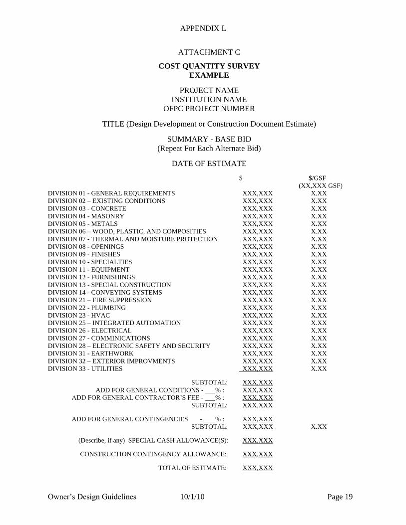
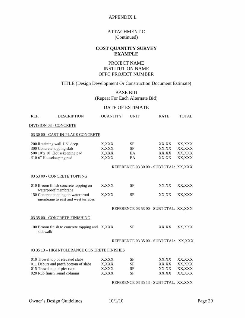
3. Construction Cost Estimate: It shall be based upon itemized quantities of unit
costs and components, overhead and profit, escalation, and administrative
expenses. See Attachment C, Cost Quantity Survey, for an example of a Cost
Quantity Survey in a form acceptable to the Owner.
Construction Cost Estimate shall be based upon detailed quantities and unit
costs for all materials, labor, equipment, building systems, General
Conditions, fees and contingencies in the CSI Master Format, current edition,
and/or the Uniformat Assemblies format, and shall address and include cost
values that reflect anticipated market conditions at time of defined
procurement and construction durations.
APPENDIX L
Owner‟s Design Guidelines 10/1/10 Page 14
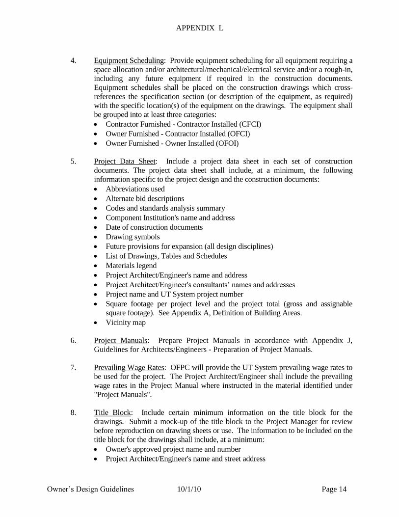
4. Equipment Scheduling: Provide equipment scheduling for all equipment requiring a
space allocation and/or architectural/mechanical/electrical service and/or a rough-in,
including any future equipment if required in the construction documents.
Equipment schedules shall be placed on the construction drawings which cross-
references the specification section (or description of the equipment, as required)
with the specific location(s) of the equipment on the drawings. The equipment shall
be grouped into at least three categories:
Contractor Furnished - Contractor Installed (CFCI)
Owner Furnished - Contractor Installed (OFCI)
Owner Furnished - Owner Installed (OFOI)
5. Project Data Sheet: Include a project data sheet in each set of construction
documents. The project data sheet shall include, at a minimum, the following
information specific to the project design and the construction documents:
Abbreviations used
Alternate bid descriptions
Codes and standards analysis summary
Component Institution's name and address
Date of construction documents
Drawing symbols
Future provisions for expansion (all design disciplines)
List of Drawings, Tables and Schedules
Materials legend
Project Architect/Engineer's name and address
Project Architect/Engineer's consultants‟ names and addresses
Project name and UT System project number
Square footage per project level and the project total (gross and assignable
square footage). See Appendix A, Definition of Building Areas.
Vicinity map
6. Project Manuals: Prepare Project Manuals in accordance with Appendix J,
Guidelines for Architects/Engineers - Preparation of Project Manuals.
7. Prevailing Wage Rates: OFPC will provide the UT System prevailing wage rates to
be used for the project. The Project Architect/Engineer shall include the prevailing
wage rates in the Project Manual where instructed in the material identified under
"Project Manuals".
8. Title Block: Include certain minimum information on the title block for the
drawings. Submit a mock-up of the title block to the Project Manager for review
before reproduction on drawing sheets or use. The information to be included on the
title block for the drawings shall include, at a minimum:
Owner's approved project name and number
Project Architect/Engineer's name and street address

APPENDIX L
Owner‟s Design Guidelines 10/1/10 Page 15
Project Architect/Engineer's consultants‟ names and professional discipline(s)
Location for the date of issue of the plans with space for several revision dates
Location for professional seals
Location for the sheet title
Location for the sheet number and “___ of ___ Sheets”
APPENDIX L
Owner‟s Design Guidelines 10/1/10 Page 16
ATTACHMENT A
PENDING ISSUES REPORT
EXAMPLE
PROJECT NAME
INSTITUTION NAME
OFPC PROJECT NUMBER
Action Date Requested Requested Responsible Due Date Action Item/Comment Status
Number Action By Action Party for (Open/
Initiated Resolution Closed)
01 09/01/00 A/E Chemical storage list/quantities Institution 10/01/00 Per 50% CD review meeting Open
02 09/01/00 Institution Upgrade Roof warranty CM 10/01/00 Per 50% CD review meeting Accepted
– 9/15/00

APPENDIX L
Owner‟s Design Guidelines 10/1/10 Page 17
ATTACHMENT B
BASIC DATA
Project:_____________________________________________ Date: ___________________
Location: ___________________________________________ OFPC Project No.: ________
Areas:
Gross: __________________
Assignable: ______________
„U‟ & „SC‟ VALUES:
WALLS Type 1 Type 2 Type 3 Type 4 Type 5
„U‟
Location
GLASS Type 1 Type 2 Type 3 Type 4 Type 5
„U‟
„SC‟
Location
ROOF Type 1 Type 2 Type 3 Type 4 Type 5
„U‟
Location
FLOOR Type 1 Type 2 Type 3 Type 4 Type 5
„U‟
Location
SLAB EDGE Type 1 Type 2 Type 3 Type 4 Type 5
„U‟
Location

APPENDIX L
Owner‟s Design Guidelines 10/1/10 Page 18
ATTACHMENT B
(Continued)
BASIC DATA
COOLING SYSTEM
Tons: ___________________ GPM: ___________________
Type: ________________________________________________________________________
______________________________________________________________________________
Prime Energy Source: ___________________________________________________________
If served by central plant, has plant capacity for this project been verified? Yes: ___ No: ___
Confirmed by: _________________________________________________________________
HEATING SYSTEM
1000 BTU: ______________ Lb/Hr Steam: _____________ or GPM HW: _____________
Type: ________________________________________________________________________
______________________________________________________________________________
Prime Energy Source: ___________________________________________________________
If served by central plant, has plant capacity for this project been verified? Yes: ___ No: ___
Confirmed by: _________________________________________________________________
AIR SYSTEM
Type: ________________________________________________________________________
______________________________________________________________________________
No. of prime units: ______________________ Total CFM: ____________________________
VENTILATION RATES
CFM/person: ___________________
or CFM/sq. ft.: ___________________
or Air Chg./Hr.: ___________________
Min. O. A. ___________________ Max. O. A. __________
Vent Cycle? ___________________
PLUMBING
San. load: ________________FU _______________GPM
Cold Water: ________________FU _______________GPM
Hot Water: ________________FU _______________GPM
Storm Water: ________________FU _______________GPM
ELECTRICAL LOADS
Lighting: __________ watts/sq. ft. ____________kw total
General Power: __________ watts/sq. ft. ____________kw total
Special Power: __________ watts/sq. ft. ____________kw total
APPENDIX L
Owner‟s Design Guidelines 10/1/10 Page 19
ATTACHMENT C
COST QUANTITY SURVEY
EXAMPLE
PROJECT NAME
INSTITUTION NAME
OFPC PROJECT NUMBER
TITLE (Design Development or Construction Document Estimate)
SUMMARY - BASE BID
(Repeat For Each Alternate Bid)
DATE OF ESTIMATE
$ $/GSF
(XX,XXX GSF)
DIVISION 01 - GENERAL REQUIREMENTS XXX,XXX X.XX
DIVISION 02 – EXISTING CONDITIONS XXX,XXX X.XX
DIVISION 03 - CONCRETE XXX,XXX X.XX
DIVISION 04 - MASONRY XXX,XXX X.XX
DIVISION 05 - METALS XXX,XXX X.XX
DIVISION 06 – WOOD, PLASTIC, AND COMPOSITIES XXX,XXX X.XX
DIVISION 07 - THERMAL AND MOISTURE PROTECTION XXX,XXX X.XX
DIVISION 08 - OPENINGS XXX,XXX X.XX
DIVISION 09 - FINISHES XXX,XXX X.XX
DIVISION 10 - SPECIALTIES XXX,XXX X.XX
DIVISION 11 - EQUIPMENT XXX,XXX X.XX
DIVISION 12 - FURNISHINGS XXX,XXX X.XX
DIVISION 13 - SPECIAL CONSTRUCTION XXX,XXX X.XX
DIVISION 14 - CONVEYING SYSTEMS XXX,XXX X.XX
DIVISION 21 – FIRE SUPPRESSION XXX,XXX X.XX
DIVISION 22 - PLUMBING XXX,XXX X.XX
DIVISION 23 - HVAC XXX,XXX X.XX
DIVISION 25 – INTEGRATED AUTOMATION XXX,XXX X.XX
DIVISION 26 - ELECTRICAL XXX,XXX X.XX
DIVISION 27 - COMMINICATIONS XXX,XXX X.XX
DIVISION 28 – ELECTRONIC SAFETY AND SECURITY XXX,XXX X.XX
DIVISION 31 - EARTHWORK XXX,XXX X.XX
DIVISION 32 – EXTERIOR IMPROVMENTS XXX,XXX X.XX
DIVISION 33 - UTILITIES XXX,XXX X.XX
SUBTOTAL: XXX,XXX
ADD FOR GENERAL CONDITIONS - % : XXX,XXX
ADD FOR GENERAL CONTRACTOR‟S FEE - % : XXX,XXX
SUBTOTAL: XXX,XXX
ADD FOR GENERAL CONTINGENCIES - % : XXX,XXX
SUBTOTAL: XXX,XXX X.XX
(Describe, if any) SPECIAL CASH ALLOWANCE(S): XXX,XXX
CONSTRUCTION CONTINGENCY ALLOWANCE: XXX,XXX
TOTAL OF ESTIMATE: XXX,XXX
APPENDIX L
Owner‟s Design Guidelines 10/1/10 Page 20
ATTACHMENT C
(Continued)
COST QUANTITY SURVEY
EXAMPLE
PROJECT NAME
INSTITUTION NAME
OFPC PROJECT NUMBER
TITLE (Design Development Or Construction Document Estimate)
BASE BID
(Repeat For Each Alternate Bid)
DATE OF ESTIMATE
REF. DESCRIPTION QUANTITY UNIT RATE TOTAL
DIVISION 03 - CONCRETE
03 30 00 - CAST-IN-PLACE CONCRETE
200 Retaining wall 1‟6” deep X,XXX SF XX.XX XX,XXX
300 Concrete topping slab X,XXX SF XX.XX XX,XXX
500 10‟x 10‟ Housekeeping pad X,XXX EA XX.XX XX,XXX
510 6” Housekeeping pad X,XXX EA XX.XX XX,XXX
REFERENCE 03 30 00 - SUBTOTAL: XX,XXX
03 53 00 - CONCRETE TOPPING
010 Broom finish concrete topping on X,XXX SF XX.XX XX,XXX
waterproof membrane
150 Concrete topping on waterproof X,XXX SF XX.XX XX,XXX
membrane to east and west terraces
REFERENCE 03 53 00 - SUBTOTAL: XX,XXX
03 35 00 - CONCRETE FINISHING
100 Broom finish to concrete topping and X,XXX SF XX.XX XX,XXX
sidewalk
REFERENCE 03 35 00 - SUBTOTAL: XX,XXX
03 35 13 – HIGH-TOLERANCE CONCRETE FINISHES
010 Trowel top of elevated slabs X,XXX SF XX.XX XX,XXX
011 Deburr and patch bottom of slabs X,XXX SF XX.XX XX,XXX
015 Trowel top of pier caps X,XXX SF XX.XX XX,XXX
020 Rub finish round columns X,XXX SF XX.XX XX,XXX
REFERENCE 03 35 13 - SUBTOTAL: XX,XXX
APPENDIX L
Owner‟s Design Guidelines 10/1/10 Page 21
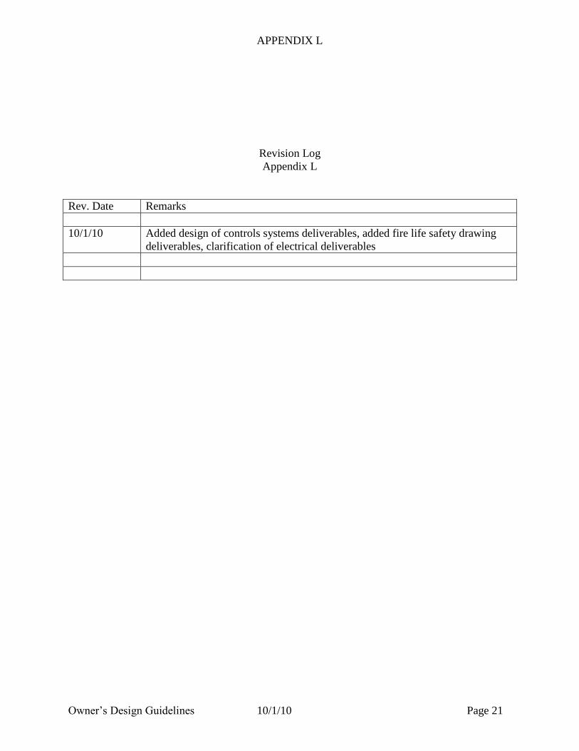
Revision Log
Appendix L
Rev. Date Remarks
10/1/10 Added design of controls systems deliverables, added fire life safety drawing
deliverables, clarification of electrical deliverables