submittal title sheet - johnson quality air® microset ii tm features wall unit • versatile...
TRANSCRIPT

SUBMITTAL SHEETSSLC1302-0700
JOB: CAPITOL THEATER PHASE ‘1’
CONTRACTOR: ALLIANCE ENERGY ANDINTERGRATION
PREPARED BY:WILSON MOHR INC.
June, 2013

1
SUBMITTAL’S June, 2013
JOB: CAPITOL THEATER PHASE ‘1’
*MS-2000H-BT ALERTON BACtalk Microset II WALL UNIT
*TS-2012-FB-10-AA ALERTON SENSOR*TS-2104-GH-10-AA ALERTON IMMERSION SENSOR*TS-3104-CI-00-AA ALERTON THERMOWELL
*VAV-SD ALERTON CONTROLLER*VLC-1188 ALERTON CONTROLLER
*B-211 BELIMO 2-WAY VALVE
*B-338 BELIMO 3-WAY VALVE
*AFRB24 BELIMO ACTUATOR
*F7100HDU-GMX24-MFT-X1 BELIMO VALVE AND ACTUAOR
*LMB24-3-T BELIMO ACTUATOR
*NMB24-SR BELIMO ACTUATOR
*TR24-3-T BELIMO ACTUATOR
*ZONE 215N-35/ZONE 120 N.O. BELIMO ZONE VALVE AND ACTUATOR
*ESD-20K-320 ENGINEERING SERVICES SURGE PROTECTOR
*RIBUIC FUNCTIONAL DEVICES CONTROL RELAY*RIBXGTA FUNCTIONAL DEVICES CURRENT SENSOR*TR50VA005 FUNCTIONAL DEVICE TRANSFORMER
*A24X24ALP HOFFMAN ENCLOSURE
*VPAS JOHNSON CONTROLS DAMPERS

2
*2601-MS1-N SETRA PRESSURE TRANSDUCER
*L8-5/1/B SPRECHER+SCHUH SUPPLEMENTARY PROECTOR

6670 185th Avenue Northeast, Redmond, WA 98052 USA • Tel: 425.869.8400 • Fax: 425.869.8445 • www.alerton.com LTBT-MSET2 Rev. 0004 1 of 2©2006 Honeywell International Inc. All rights reserved. Alerton is a registered trademark of Honeywell.
The Alerton® BACtalk® Microset™ II is an intelligent and attractive wall unit that updates the functions of the typical thermostat. The Microset II connects to Alerton’s BACtalk VisualLogic® Controllers (VLCs™) and serves as a tenant control center and fi eld service tool. Sleek styling, a backlit liquid crystal display (LCD) and simple push-button controls make operation intuitive. The LCD simultaneously displays the setpoint, room and outside air temperatures, and fan status.
An occupant can use the Microset II to view room and outside air temperatures and change setpoints within established limits. The Microset II is programmable, allowing site developers the fl exibility to display information and allow occupant control according to the varied needs of each application.
Typically, the unit displays room and outside air temperatures. But site developers can program the unit to display additional information: time-of-day, room humidity and outdoor humidity for example. The LCD shows temperatures in Fahrenheit or Centigrade.
The Microset II’s push-button operations can be customized so that an occupant can use them to turn zone HVAC equipment ON or OFF. This is useful for areas that are occupied sporadically, such as conference rooms. Push-buttons also support fan-speed control, and the LCD shows current fan-speed. An occupant can select after-hours operation in 30-minute increments up to established limits.
The Microset II communicates with programmable VLCs, which directly connect to zone mechanical equipment. The VLC stores programmed control parameters and temperature settings, executing DDC to control equipment and maintain optimum environmental conditions.
The Microset II’s programmable fi eld service mode (activated with a special code) enables maintenance personnel to view and adjust control parameters in the fi eld. This reduces maintenance and service time while providing facility personnel with increased fl exibility.
BACtalk® MICROSET II TM
WALL UNITFeatures
• Versatile Occupant can view room and outside air temperatures, select fan speed and change room temperature setpoints. Data and functions are programmable.
• Energy Effi cient Occupants can select after-hours operation in 30-minute increments or turn zone equipment ON and OFF.
• Flexible A programmable fi eld service mode allows maintenance personnel to monitor and adjust control parameters in the VLC from the Microset’s fi eld service mode.
• Attractive Modern styling enhances any interior, and functional design makes operation intuitive.

6670 185th Avenue Northeast, Redmond, WA 98052 USA • Tel: 425.869.8400 • Fax: 425.869.8445 • www.alerton.com 2 of 2 LTBT-MSET2 Rev. 0004
©2006 Honeywell International Inc. All rights reserved. Alerton is a registered trademark of Honeywell.
Technical data
Specifi cations subject to change without notice
Thermistor The thermistor is integrated with the device. The unit is a microprocessor with a built-in analog to digital converter for temperature and humidity which is designed to communicate directly to VLCs.
Type Uni-curve Type IIResistance 10KΩ at 77°F (22°C).Interchangeability 0.36°F (0.2°C).Time Constant* 10 seconds (to 66% of new temperature).Stability* 0.036°F (0.02°C) drift per year.Accuracy* ± 0.36°F (0.2°C) over range of 32–158°F (0–70°C).*Based on normal operating conditions.
Power 24 VAC @ 25 mA for backlit display. Orange lead terminates to 24 VAC terminal on VLC. Sensor draws 5 VDC @ 10 mA from VLC.
VLC Connection 18–22 AWG, shielded, 3-conductor. 1000 ft. max. Black wire to VLC IN, white to VLC input COM, orange is optional 24 VAC for backlit display. Low capacitance wire recommended.
Dimensions 4.6” (117mm) H X 3.0” (76mm) L X 0.7” (18mm) D.
Environmental 32–158°F (0–70°C). 0–90% RH, non-condensing.
Optional Humidity Sensor ± 2% RH, 0–100% RH @ 25°C, with saturated salt calibration. -40–185°F (-40–85°C). ± 0.5% RH. ± 5% RH up to 60%RH, ± 8% RH at 90% RH (typical humidity).
Ratings
• Listed Underwriters Laboratory as an accessory for VAVs and VLCs. • EMC Directive 89/336/EEC (European CE Mark). Pending. • FCC Part 15, Subpart J, Class A. Pending.
Ordering information
Item number Description
MS-2000-BTMS-2000H-BT (with optional humidity sensor)
BACtalk® MICROSET II TM
WALL UNIT

2305 Pleasant View Rd. Middleton Industrial Park Middleton, WI 53562PH: (608) 831-2585 FAX (608) 831-7407
www.workaci.comFilename: C0000025 Rev 3.Doc
Product Data
Duct Sensor w/ Flange and 6 Foot Plenum Cable
TS-2000-FB Series
Product DescriptionThe TS-2000-FB Series duct temperature sensors have an output of 3K Ohms at 77oF (25oC) and 10K Ohms (Type II) at 77oF (25oC). The temperature
8.1 fo ycarucca llarevo na evah srosnes oF (1.0oC) over the range of 32 to 158oF (0 to 70oC).
Each of the sensors is encapsulated in a 0.250“ (6.35 mm) stainless steel probe with a thermally conductive epoxy. The TS-2000-FB Series temperature sensors can be used in environments where the operating temperature is between –40 to 302oF (-40 to 150oC).
The TS-2000-FB Series duct temperature sensors are both non-polarity and non-position sensitive. Each single point Thermistor sensor is encapsulated in a thermally conductive epoxy that will withstand high
operating temperatures and protect the sensor from condensation or moisture.
All of these sensors should be used in environments where the normal operating temperature will be between –40 to 302oF (-40 to 150oC).
There are a number of applications in which the TS-2000-FB Series may be used to monitor and control the building temperature. A few of the most common applications include:
Return Air Temperature in a Duct or Plenum Mixed Air Temperature in a Duct or Plenum Monitoring Discharge (Supply) Air Temp.
All of these units come with a five-year warranty. For more information regarding these products, please contact ACI at the numbers listed below, or visit our website address at www.workaci.com for all of the up to date product literature.
Product SpecificationsOutput 3K Ohms @ 77oF (25oC)
10K Ohms (Type II) @ 77oF (25oC)TS –2000-FB SeriesSensor Accuracy
+/-1.8oF (+/-1.0oC)32 to 158oF (0 to 70oC)
Operating Temperature Range -40 to 302oF (-40 to 150oC)
Sensor Interchangeability +/-0.2oC (0 to 70oC) Operating Humidity Range 0 to 90% RH non-condensingDissipation Constant 3mW / oC nominal (Still Air) Environmental Compliance RoHS-Directive 2002/95/EC
Features
* Stainless Steel Probe* Fast Response Time* High Accuracy* 6’ Teflon Plenum Rated Cable* 5-year Warranty* ROHS Compliant

2305 Pleasant View Rd. Middleton Industrial Park Middleton, WI 53562PH: (608) 831-2585 FAX (608) 831-7407
www.workaci.comFilename: C0000025 Rev 3.Doc
Dimensions
Ordering Information
These units are manufactured for Alerton by Automation Components, Inc.
Temp. C Temp. F 3K (R Ohms)10K(TypeII)
(R Ohms)
-40 -40 100,935.00 336,450.00
-30 -22 53,164.50 177,207.53
-20 -4 29,172.86 97,236.73
-10 14 16,623.95 55,409.40
0 32 9,808.20 32,692.05
10 50 5,975.03 19,915.94
20 68 3,748.67 12,495.39
30 86 2,416.51 8,055.16
40 104 1,597.15 5,324.13
50 122 1,080.22 3,601.05
60 140 746.30 2,488.00
70 158 525.85 1,753.13
80 176 377.32 1,258.03
90 194 275.36 918.12
100 212 204.13 680.64
110 230 153.54 511.99
120 248 117.07 390.39
130 266 90.40 301.46
140 284 70.63 235.56
150 302 55.80 186.10
Alerton Model # Sensor Type Wire Colors Ref ATS-2004-FB-03-AA 3K Ohms Red / Black 3.87” (98.3 mm)TS-2004-FB-10-AA 10K Ohms Red / Black 3.87” (98.3 mm)
TS-2004-FB-10-AA-HI 10K HI Orange / Orange 3.87” (98.3 mm)TS-2006-FB-03-AA 3K Ohms Red / Black 5.75” (146.05 mm)TS-2006-FB-10-AA 10K Ohms Red / Black 5.75” (146.05 mm)TS-2008-FB-03-AA 3K Ohms Red / Black 7.87” (199.9 mm)TS-2008-FB-10-AA 10K Ohms Red / Black 7.87” (199.9 mm)TS-2012-FB-03-AA 3K Ohms Red / Black 11.84” (300.74 mm)TS-2012-FB-10-AA 10K Ohms Red / Black 11.84” (300.74 mm)
Ref A
0.66” (16.76 mm)
0.05” (1.27 mm)
3.89”(98.81 mm)
(2) 0.18” (4.57 mm)X 0.62” (15.75 mm)
Mounting Holes
0.25” (6.35 mm)Mounting Hole
0.75”(19.05 mm)

2305 Pleasant View Rd. Middleton Industrial Park Middleton, WI 53562www.workaci.com
PH: (608) 831-2585 FAX (608) 831-7407Filename: C0000029 Rev 2.Doc
Product Data
Immersion Sensor w/ Galvanized Junction Box
TS-2100-GH Series
Product DescriptionThe TS-2100-GH Series single point immersion temperature sensors have an output of 3K Ohms at 77°F (25°C) and 10K Ohms (Type II) at 77°F (25°C)respectively. . The temperature sensors have an overall accuracy of ± 1.8°F (±1.0°C) over the temperature range of 32 to 185°F (0 to 85°C).
All of the immersion temperature sensors shall have two 22 AWG colored Etched Teflon lead wires for making all of your field connections. Please note that the TS-2100-GH Series immersion temperature sensors are both non-polarity and non-position sensitive when mounting the units. Each single point thermistor sensor is encapsulated in a thermally conductive epoxy that will withstand high operating temperatures and will protect the sensor from condensation or moisture.
All of these sensors should be used in environments where the normal operating temperature will be between -40 to 302oF (-40 to 150oC).
There are a number of applications in which the TS-2100-GH Series may be used to monitor and control the building temperature. A few of the most common applications include:
Monitoring Boiler Temperatures Monitoring Chilled Water Temperature Monitoring Hot Water Temperature Monitoring High Pressure Air Temperatures
All of these units come with a two-year warranty. For more information regarding these products, please contact ACI at the numbers listed below, or visit our website address at www.workaci.com for all of the up to date product literature
Product SpecificationsOutput 3K Ohms @ 77°F (25°C)
10K Ohms Type II @ 77°F (25°C)TS-2100-GH SeriesAccuracy
± 1.0°C (0 to 70°C)
Operating Temp. Range -40 to 302°F (-40 to 150°C)
Interchangeability ± 0.2°C (0 to 70°C) Operating Humidity Range 0 to 90% RH non-condensing
Dissipation Constant 3mW / °C
Features
* NEMA 1 Rated Enclosure * Eight (8) ½” Conduit Knockouts* ¼” Diameter Stainless Steel Probe* Extremely Reliable

2305 Pleasant View Rd. Middleton Industrial Park Middleton, WI 53562www.workaci.com
PH: (608) 831-2585 FAX (608) 831-7407Filename: C0000029 Rev 2.Doc
Dimensions
Ordering Information
These units are manufactured for Alerton by Automation Components, Inc.
Temp. C Temp. F 3K (R Ohms)10K(Type II)
(R Ohms)
-40 -40 100,935.00 336,450.00
-30 -22 53,164.50 177,207.53
-20 -4 29,172.86 97,236.73
-10 14 16,623.95 55,409.40
0 32 9,808.20 32,692.05
10 50 5,975.03 19,915.94
20 68 3,748.67 12,495.39
30 86 2,416.51 8,055.16
40 104 1,597.15 5,324.13
50 122 1,080.22 3,601.05
60 140 746.30 2,488.00
70 158 525.85 1,753.13
80 176 377.32 1,258.03
90 194 275.36 918.12
100 212 204.13 680.64
110 230 153.54 511.99
120 248 117.07 390.39
130 266 90.40 301.46
140 284 70.63 235.56
150 302 55.80 186.10
Alerton Model # Sensor Type Wire Colors Ref ATS-2104-GH-03-AA 3K Ohms Blue / Blue 5.75” (146.1 mm)
TS-2104-GH-10-AA 10K Ohms Yellow / Yellow 5.75” (146.1 mm)
TS-2104-GH-10-AA-HI 10K Ohms HI Orange / Orange 5.75” (146.1mm)
TS-2106-GH-03-AA 3K Ohms Blue / Blue 7.88” (200.2 mm)
TS-2106-GH-10-AA 10K Ohms Yellow / Yellow 7.88” (200.2 mm)
TS-2108-GH-03-AA 3K Ohms Blue / Blue 9.78” (248.4 mm)
TS-2108-GH-10-AA 10K Ohms Yellow / Yellow 9.78” (248.4 mm)
TS-2125-GH-03-AA 3K Ohms Blue / Blue 4.38” (111.3 mm)
TS-2125-GH-10-AA 10K Ohms Yellow / Yellow 4.38” (111.3 mm)
1/2” NPSM Straight Threads
Ref A
(8) ½” Conduit Knockouts
Single GangJunction Cover
1.70” (43.2 mm)
2.09” (53.1 mm)
1.16” (29.5 mm)
4.19” (106.4 mm)
2.32” (58.9 mm)

2305 Pleasant View Rd. Middleton Industrial Park Middleton, WI 53562PH: (608) 831-2585 FAX (608) 831-7407
www.workaci.comFilename: C0000034 Rev 2.Doc
Product Data
Stainless Steel Thermowell
TS-3100-CI Series
Product DescriptionThe TS-3100-CI Series thermowells are made of 304 series stainless steel to ensure long lasting reliability and stability. These units are machined to high tolerances, so that there is no gap between the thermowell sheath and the probe, to provide maximum heat transfer.
If preferred, thermal grease may be used with all of the thermowells. ACI offers thermal grease in both a silicone and non-silicone compound. The silicone compound is available in a 1.5 oz. jar and the non-silicone grease is available in a 2 oz. tube.
The TS-3100-CI Series thermowells are a 2-part thermowell. The sheath is set into the nut and then welded with an automated tig welder for consistency and from its own material to provide the strongest possible joint. The nut is machined from a 1.125” (28.58 mm) 304 series stainless steel bar stock.
The TS-3100-CI Series thermowells may be used with any liquid, fluid, or gas that is compatible with 304 series stainless steel.
All of these units come with a five year warranty. For more information regarding these products, please contact ACI at the numbers listed below, or visit our website address at www.workaci.com for all of the up to date product literature.
Product Specifications Material 304 Series Stainless SteelThermowell Bore 0.260” +/- 0.002” (Accepts 0.250”
O.D Probe Diameters)Environmental Compliance ROHS-Directive 2002/95/EC
Maximum Pressure Rating vs. Temperature ChartPressure (PSI) Temperature oF (oC)
1600 70oF (21.09oC)1500 200 oF (93.24oC)1400 400 oF (204.24oC)1200 600 oF (315.24oC)1000 800 oF (426.24oC)900 1000 oF (537.24oC)700 1200 oF (648.24oC)
Features
* 1/2” NPT Male Process Thread* 1/2” NPSM Female Instrument Thread* 2-Part Welded Thermowell * 304 Series Stainless Steel* 2-year Warranty* ROHS Compliant

2305 Pleasant View Rd. Middleton Industrial Park Middleton, WI 53562PH: (608) 831-2585 FAX (608) 831-7407
www.workaci.comFilename: C0000034Rev 2.Doc
Dimensions
Ordering Information
These units are manufactured for Alerton by Automation Components, Inc.
Alerton Model #Insertion Length
(Ref A)Overall Length
(Ref B)TS-3104-CI-00-AA 4.00” (101.6 mm) 5.75” (146.05 mm)TS-3106-CI-00-AA 6.25” (158.75 mm) 8.00” (203.2 mm)TS-3108-CI-00-AA 8.00” (203.2 mm) 9.75” (247.65 mm)TS-3125-CI-00-AA 2.50” (63.5 mm) 4.25” (107.95 mm)
Ref A
Ref B
1/2” Male NPT (Process Thread)
½” NPSM(Instrument Thread)
0.38”(9.65 mm)
Tig Welded

6670 185th Avenue Northeast, Redmond, WA 98052 USA • Tel: 425.869.8400 • Fax: 425.869.8445 • www.alerton.comPage 1 of 2 LTBT-VAV-SD Rev. 0003
©2006 Honeywell International Inc. All rights reserved.
VAV-SD
Features and highlights
• CapableFour 10-bit inputs and fi ve binary outputs.
• InteroperableFully BACnet-compliant on MS/TP LAN at up to 76.8 Kbps.
• VersatileDownloadable operating code to allow for future software improvements.
• ReliableExtensive onboard fi ltering, with all program data backed up in non-volatile Flash memory.
• AccurateFactory calibrated at multiple velocity points and fi eld-adjustable during balancing.
The Alerton® BACtalk® VAV-SD controller is a versatile BACnet-compliant fi eld controller that provides pressure-independent control of any single duct variable air volume (VAV) box. As a native BACnet controller, the VAV-SD integrates seamlessly with your BACnet system, communicating at up to 76.8 Kbps on a BACnet MS/TP LAN.
The BACtalk VAV-SD contains an integral airfl ow sensor to provide pressure-independent operation of the VAV box. Each airfl ow sensor is factory-calibrated at multiple velocity points. Minimum, maximum, and reheat airfl ows can be entered either at a Microset wall unit or an operator workstation. A technician can adjust the calibration in the fi eld during balancing to compensate for slight variations in box installation and type.
All control algorithms are factory-loaded into non-volatile Flash memory and can be fi eld-modifi ed. The VAV-SD can execute control algorithms independently of other equipment. All calibration, programming, and operator-entered setup data is stored in Flash memory for further assurance of stable, reliable, and independent operation.
The BACtalk VAV-SD is your complete answer to control of all single duct VAV boxes in a BACnet environment. With its integral airfl ow sensor and programming fl exibility, the VAV-SD provides every option for precision VAV box control.

6670 185th Avenue Northeast, Redmond, WA 98052 USA • Tel: 425.869.8400 • Fax: 425.869.8445 • www.alerton.comPage 2 of 2 LTBT-VAV-SD Rev. 0003
©2006 Honeywell International Inc. All rights reserved.
VAV-SD
Technical Data• Power 24 VAC @ 5 VA min., plus binary output loads (65 VA max). Utilizes a half-wave
rectifier, which allows a single transformer to power multiple VLCs. One leg of 24 VAC connects to earth (panel) ground.
• Inputs 4 universal inputs with 10-bit resolution. Input 0 can be used for a BACtalk® Microset™. Inputs 1–3 support thermistor/dry contact.
• Binary outputs 5 outputs, each rated at 24 VAC, 0.5 A. Three outputs utilize hot-switched triacs. Two outputs utilize ground switching triacs for damper motor control. All outputs have a common connection to the fused 24 VAC supply.
• Pressure sensor 0–1.25 inches water column differential pressure sensor.
• Processor and memory Motorola AZ-60 processor with onboard Flash memory. Flash memory provides non-volatile program and data storage and allows for encrypted updates to the program for future product enhancements .
• Dimensions 5.20” (132mm) H x 3.30” (84mm) W x 1.40” (36mm) D.
• Terminations Removable header-type screw terminals accept 14–24 AWG wire. An additional header is provided for easy connection to MS/TP for testing.
• Environmental 0–158°F (-17–70°C). 0–95% RH, non-condensing.
• Communications BACnet MS/TP LAN up to 76.8 Kbps.
• BACnet conformance An application specific controller (ASC); tested and approved by BTL. See Protocol Implementation Conformance Statement (PICS).
• Ratings
Listed Underwriters Laboratory for Open Energy Management
Equipment (PAZX) under the UL Standard for Safety 916. Listing includes both U.S. and Canadian certification.
EMC Directive 89/336/EEC (European CE Mark).
FCC Part 15, Subpart J, Class A.
Ordering InformationItem number Description
VAV-SD Single-duct variable air volume controller
Specifications subject to change without notice.
BACnet is a registered trademark of ASHRAE. ASHRAE does not endorse,
approve or test products for compliance with ASHRAE standards. Compliance of
listed products to requirements of ASHRAE Standard 135 is the responsibility of
the BACnet Manufacturers Association (BMA). BTL is a registered trademark of
the BMA.

6670 185th Avenue Northeast, Redmond, WA 98052 USA • Tel: 425.869.8400 • Fax: 425.869.8445 • www.alerton.com2 of 2 LTBT-VLC-1188 Rev. 0003
© Honeywell International Inc. All rights reserved. Alerton is a registered trademark of Honeywell.
VLC-1188
Features and highlights
• Capable Eleven 10-bit universal inputs, eight binary outputs, and eight analog outputs.
• Interoperable Fully BACnet-compliant on MS/TP LAN at up to 76.8 Kbps.
BACnet is a registered trademark of ASHRAE. ASHRAE does not endorse, approve or test products for compliance with ASHRAE standards. Compliance of listed products to requirements of ASHRAE Standard 135 is the responsibility of the BACnet Manufacturers Association (BMA). BTL is a registered trademark of the BMA.
• Versatile Fully programmable and capable of stand-alone operation.
• Reliable AZ60 processor and extensive on-board filtering, with all program data backed up in nonvolatile flash memory.
• Fast Internal logic loop of 100 msec. The Alerton® BACtalk® VLC-1188 is a versatile, fully programmable logic
controller designed for central plant systems, air handling units, clean rooms, fume hoods, large terminal units, and similar control and process equipment. As a native BACnet controller, it integrates seamlessly with your BACnet system, communicating on a BACnet MS/TP LAN at up to 76.8 Kbps.
The VLC-1188 supports the Alerton Microtouch™, as well as the Microset™ and Microset II intelligent wall sensors, which offer convenient data display, setpoint adjustment, and technician access to equipment setup parameters.
All VLC-1188 control logic is programmed with Alerton’s easy-to-learn graphical programming language, VisualLogic™. Programming and setup data is stored in nonvolatile flash memory, ensuring stable and reliable operation.
High-resolution 10-bit analog inputs are field-adjustable for thermistor/dry contact, 0–5 VDC/4–20 mA, or 0–10 VDC. Analog outputs are switch-selectable for 4–20 mA or 0–10 VDC.

6670 185th Avenue Northeast, Redmond, WA 98052 USA • Tel: 425.869.8400 • Fax: 425.869.8445 • www.alerton.com2 of 2 LTBT-VLC-1188 Rev. 0003
© Honeywell International Inc. All rights reserved. Alerton is a registered trademark of Honeywell.
Technical Data
• Power 24 VAC @ 20 VA min., plus binary output loads (110 VA max). Utilizes a half-wave rectifier, which allows a single transformer to power multiple VLCs. One leg of 24 VAC connects to earth (panel) ground.
• Inputs 11 universal inputs with 10-bit resolution. Input 0 can be used for a BACtalk® Microset™ or Microset II. Inputs 1–10 are jumper-selectable for thermistor/dry contact, 0–5 VDC/4–20 mA., or 0–10 VDC signals.
• Binary Outputs 8 outputs each rated at 24 VAC, 0.5A. The outputs utilize optically coupled triacs, which have a common connection to the fused 24 VAC supply.
• Analog Output 8 outputs with 8-bit resolution. Each is switch-selectable for 0–10 VDC or 4–20 mA. 4–20 mA outputs are sourced by the VLC. Connected loads must return to the VLC ground. 4–20 mA max. load resistance is 1,000 ohm. 0–10 VDC min. load resistance is 500 ohm.
• 24VDC Output Up to 100 mA of 24 VDC power is provided to power transducers or other devices.
• Processor & Memory Motorola AZ60 processor with on-board flash memory. Flash memory provides nonvolatile program and data storage, and allows for encrypted updates to the program for future product enhancements.
• Dimensions 6.98” (177mm)H x 5.0” (127mm)W x 1.5” (38mm)D.
• Terminations Removable header-type screw terminals accept 14–24 AWG wire.
• Environmental 0–158 deg. F (-17–70 deg. C). 0–95% RH, non-condensing.
• Communications BACnet MS/TP LAN up to 76.8 Kbps.
• BACnet Conformance B-ASC level device; tested and approved by BTL. See Protocol Implementation Conformance Statement (PICS).
VLC-1188
BACnet is a registered trademark of ASHRAE. ASHRAE does not endorse, approve or test products for compliance with ASHRAE standards. Compliance of listed products to requirements of ASHRAE Standard 135 is the responsibility of the BACnet Manufacturers Association (BMA). BTL is a registered trademark of the BMA.
Specifications subject to change without notice
• Ratings
Listed Underwriters Laboratory for Open Energy Management Equipment (PAZX) under the UL Standard for Safety 916; listing includes both U.S. and Canadian certification
Suitable for plenum mounting
EMC Directive 89/336/EEC (European CE Mark)
FCC Part 15, Subpart J, Class A
Ordering Information Item number Description
VLC-1188 BACtalk field controller for central plant systems application with 11 inputs, 8 binary triac outputs, 8 analog outputs
VLC-1188-C VLC-1188 field controller with available custom DDC

800-543-9038 USA 866-805-7089 CANADA 203-791-8396 LATIN AMERICA
88
O509
05 -
05/1
2 - S
ubje
ct to
cha
nge.
© B
elim
o Ai
rcon
trols
(USA
), In
c.
AFRB Actuators, On/Off AFRB24(-S), AFRX24(-S) Actuators, On/Off
ModelsAFRB24AFRB24-SAFRX24AFRX24-S
Technical DataPower supply 24 VAC ± 20% 50/60 Hz
24 VDC +20% / -10%Power consumption running 5 W
holding 2.5 WTransformer sizing 7.5 VA (class 2 power source)Electrical connection
AFRB24... 3 ft., 18 GA appliance cable, 1/2" conduitconnector-S models: two 3 ft., 18 gauge appliancecables with 1/2” conduit connectors
AFRX24... 3 ft. [1m], 10 ft. [3m] or 16 ft. [5m] 18 GA appliance or plenum cables, with or without 1/2” conduit connector-S models: two 3 ft. [1m], 10 ft. [3m] or16 ft. [5m] appliance cables, with or without 1/2" conduit connectors
Overload protection electronic throughout 0 to 95° rotationControl on/offDirection of rotation spring reversible with CW/CCW mountingAngle of rotation 95°Running time motor < 75 seconds
spring 20 seconds @ -4°F to 122°F [-20°C to 50°C];< 60 seconds @ -22°F [-30°C]
Position indication visual indicator, 0° to 95°(0° is full spring return position)
Manual override 5 mm hex crank (3/16" Allen), suppliedAmbient temperature -22°F to 122°F [-30°C to 50°C]Storage temperature -40°F to 176°F [-40°C to 80°C]Housing NEMA 2, IP54, Enclosure Type2Agency listings † cULus according. to UL60730-1A/-2-14,
CAN/CSA E60730-1:02, CE according. to2004/108/EC & 2006/95/EC
Noise level <50dB(A) motor @ 75 seconds<62dB(A) spring return
Quality standard ISO 9001† Rated Impulse Voltage 800V, Type of action 1.AA (1.AA.B for -S version), Control Pollution Degree 3.
AFRB24-S, AFRX24-S
Auxiliary switches 2 x SPDT 3A (0.5A) @ 250 VAC, UL approvedone set at +10°, one adjustable 10° to 90°
Dimensions

800-543-9038 USA 866-805-7089 CANADA 203-791-8396 LATIN AMERICA
89
O509
05 -
05/1
2 - S
ubje
ct to
cha
nge.
© B
elim
o Ai
rcon
trols
(USA
), In
c.
Wiring Diagrams
1 Provide overload protection and disconnect as required.
2 CAUTION Equipment Damage!Actuators may be connected in parallel.Power consumption and input impedance must be observed.
3 Actuators may also be powered by 24 VDC.
4For end position indication, interlock control, fan startup, etc., AFRB24-S and AFRX24-S incorporates two built-in auxiliary switches: 2 x SPDT, 3A (0.5A) @250 VAC, UL Approved, one switch is fi xed at+10°, one is adjustable 10° to 90°.
Meets cULus requirements without the need of an electrical ground connection.
WARNING Live Electrical Components!GDuring installation, testing, servicing and troubleshooting of this product, it may
be necessary to work with live electrical components. Have a qualifi ed licensed electricianor other individual who has been properly trained in handling live electrical componentsperform these tasks. Failure to follow all electrical safety precautions when exposed to live electrical components could result in death or serious injury.
1 Common
2 + Hot
1
2
24 VAC Transformer
AFB24, AFB24-SAFX24, AFX24-S
Line Volts 3
W06
3_AF
B(X)
On/Off wiring for AFRB24, AFRX24
AFB24-SAFX24-S
W06
4_AF
B(X)
_-S
Auxiliary Switches for AFRB24-S, AFRX24-S
AFRB24(-S), AFRX24(-S) Actuators, On/Off

800-543-9038 USA 866-805-7089 CAnAdA 203-791-8396 LAtin AmeriCA
8
B2 Series, 2-Way, Characterized Control Valve Chrome Plated Brass Ball and Brass Stem
technical DataService chilled or hot water, 60% glycolFlow characteristic A-port equal percentage Action 90° rotationSizes ½”, ¾”type of end fitting nPt female endsmaterials:
BodyBallStemSeatsCharacterizing discPacking
forged brass, nickel platedchrome plated brassnickel plated brassPtFetefzel® 2 ePdm O-rings, lubricated
Pressure rating 600 psi media temp. range 0°F to 212°F [-18°C to 100°C]Close off pressure 200 psimaximum differential
pressure (∆P)30 psi for typical applications
Leakage 0% for A to ABCv rating A-port: see product chart for valuestefzel® is a registered trademark of duPont
Dimensions
2Way
Valv
e-B2
07-B
220
Valve nominal size Dimensions (inches [mm])Valve Body inches Dn [mm] a B
B207B-B211B ½” 15 2.41” [61.1] 1.39” [35.2]B212B-B215B ½” 15 2.38” [60.4] 1.72” [43.7]B217B-B220B ¾” 20 2.73” [69.3] 1.81” [45.9]
Flow Patterns
applicationthis valve is typically used in air handling units on heating or cooling coils, and fan coil unit heating or cooling coils. Some other common applications include Unit Ventilators, VAV box re-heat coils and bypass loops. this valve is suitable for use in a hydronic system with variable flow.
Valve nominal size type suitable return actuatorscv inches Dn [mm] 2-way nPt non-spring spring 0.3 ½ 15 B207B
tr s
erie
s
lr s
erie
s
tF s
erie
s
lF s
erie
s
0.46 ½ 15 B208B0.8 ½ 15 B209B1.2 ½ 15 B210B1.9 ½ 15 B211B3 ½ 15 B212B
4.7 ½ 15 B213B7.4 ½ 15 B214B10 ½ 15 B215B*4.7 ¾ 20 B217B7.4 ¾ 20 B218B10 ¾ 20 B219B24 ¾ 20 B220B*
*models without characterizing disc
K209
03 -
04/0
8 - S
ubje
ct to
cha
nge.
© B
elim
o Ai
rcon
trols
(USA
), in
c.

800-543-9038 USA 866-805-7089 CAnAdA 203-791-8396 LAtin AmeriCA
11
applicationthis valve is typically used in air handling units on heating or cooling coils, and fan coil unit heating or cooling coils. Some other common applications include Unit Ventilators, VAV box re-heat coils and bypass loops. this valve is suitable for use in a hydronic system with variable or constant flow.
B3 Series, Three Way, Characterized Control ValveStainless Steel Ball and Stem
Valve nominal size type suitable return actuatorscv inches Dn [mm] 3-Way nPt non-spring spring 0.3 ½ 15 B307
tr s
erie
s
lr s
erie
s
nr..
.n4
serie
s
tF s
erie
s
lF s
erie
s
0.46 ½ 15 B3080.8 ½ 15 B3091.2 ½ 15 B3101.9 ½ 15 B3113 ½ 15 B312
4.7 ½ 15 B31310 ½ 15 B315*4.7 ¾ 20 B31724 ¾ 20 B320*7.4 1 25 B32210 1 25 B32330 1 25 B325*10 1¼ 32 B329
ar s
erie
s
ar..
.n4
serie
s
aF s
erie
s
19 1¼ 32 B33025 1¼ 32 B33119 1½ 40 B33829 1½ 40 B33937 1½ 40 B34046 1½ 40 B34129 2 50 B34737 2 50 B34846 2 50 B34957 2 50 B35068 2 50 B35183 2 50 B352
*models without characterizing disc
Flow Patterns“B” Port must be piped to the
bypass leg.
technical DataService chilled or hot water, 60% glycolFlow characteristic A-port equal percentage
B-port modified for constant common port flow
Action 90° rotationSizes ½”, ¾”, 1”, 1¼”, 1½”, 2”type of end fitting nPt female endsmaterials:
BodyBallStemSeatsCharacterizing discPacking
forged brass, nickel platedstainless steelstainless steelPtFetefzel® 2 ePdm O-rings, lubricated
Body Pressure rating600 psi400 psi
½” - 1”1¼” - 2”
media temp. range 0°F to 212°F [-18°C to 100°C]Close off pressure
200 psi ½” - 2”maximum differential
pressure (∆P)30 psi for typical applications
Leakage 0% for A to AB<2.0% for B to AB
Cv rating A-port: see product chart for values B-port: 70% of A to AB Cv
tefzel® is a registered trademark of duPont
Dimensions
3Way
Valv
e-B3
07-B
320
Valve nominal size Dimensions (inches [mm])Valve Body inches Dn [mm] a B cB307-B311 ½” 15 2.41” [61.1] 1.39” [35.2] 1.20” [30.6]B312-B315 ½” 15 2.38” [60.4] 1.72” [43.7] 1.26” [32.1]B317-B320 ¾” 20 2.73” [69.3] 1.81” [45.9] 1.45” [36.8]B322-B325 1” 25 3.09” [78.4] 1.81” [45.9] 1.56” [39.8]B329-B331 1¼” 32 3.96” [100.6] 2.21” [56.2] 2.14” [54.3]B338-B341 1½” 40 4.39” [111.6] 2.45” [62.2] 2.33” [59.1]B347-B352 2” 50 4.90” [124.5] 2.68” [68.0] 2.60” [66.0]
K209
03 -
04/0
8 - S
ubje
ct to
cha
nge.
© B
elim
o Ai
rcon
trols
(USA
), in
c.

800-543-9038 USA 866-805-7089 CANADA 203-791-8396 LATIN AMERICA
9
F7…HDU Butterfl y Valves 2”–12” Ductile Iron Lug BodyResilient Seat, 304 Stainless Disc
Technical DataService chilled, hot water, 60% glycolFlow characteristic modifi ed linearAction 90° rotationSizes 2” to 12”Type of end fi tting for use with ANSI 125/150 fl angesMaterials
BodyBody fi nishDiscSeatShaftO-ringUpper bushingMiddle bushingsLower bushing
ductile iron ASTM A536epoxy powder fi nish304 stainless steelEPDM standard416 stainless steelEPDMRPTFERPTFERPTFE
Media temperature range -22°F to 250°F [-30°C to 120°C]Operation ambienttemperature range -22°F to 122°F [-30°C to 50°C]Body pressure rating ASME/ANSI Class 125/150
(200 psi at -30°F to 275°F)Close-off pressure 50 psiRangeability 10:1 (for 30° to 70° range)Maximum velocity 12 FPS
• 50 psi bubble tight shut-off• Long stem design allows for 2” insulation• Valve face-to-face dimensions comply with API 609 & MSS-SP-67• Completely assembled and tested, ready for installation• Tees comply with ASME/ANSI B16.1 Class 125 fl anges
ApplicationThese valves are designed to meet the needs of HVAC and commercialapplications requiring bubble tight shut off for liquids. Typical applicationsinclude chiller isolation, cooling tower isolation, change-over systems, largeair handler coil control, bypass and process control applications. The large Cv values provide for an economical control valve solution for larger fl ow applications. Designed for use in Victaulic piping systems when mated toVictaulic 41 series fl ange nipples.
Jobsite NoteValves should be stored in a weather protected area prior to construction.Complete installation recommendations can be found in Belimo’s Installationand Maintenance Instructions for F6/F7…HD/HDU Butterfl y Valves.
ValveNominal Size Type Suitable Actuators
Cv 90°
Cv 60° IN DN
[mm] 3-way Spring Non-Spring
115 44 2” 50 F750HDU
AFSe
ries AM
SY S
erie
s
196 75 2½” 65 F765HDU
GM S
erie
s
302 116 3” 80 F780HDU600 230 4” 100 F7100HDU1022 392 5” 125 F7125HDU1579 605 6” 150 F7150HDU3136 1202 8” 200 F7200HDU5340 2047 10” 250 F7250HDU8250 3062 12” 300 F7300HDU
MOD ON/OFFValve Size Cv 10° 20° 30° 40° 50° 60° 70° 80° 90°F750HDU 2” 115 .06 3 7 15 27 44 70 105 115F765HDU 2½” 196 .10 6 12 25 45 75 119 178 196F780HDU 3” 302 .20 9 18 39 70 116 183 275 302F7100HDU 4” 600 .30 17 36 78 139 230 364 546 600F7125HDU 5” 1022 .50 29 61 133 237 392 620 930 1022F7150HDU 6” 1579 .80 45 95 205 366 605 958 1437 1579F7200HDU 8” 3136 2 89 188 408 727 1202 1903 2854 3136F7250HDU 10” 5340 3 151 320 694 1237 2047 3240 4859 5340F7300HDU 12” 8250 4 234 495 1072 1911 3062 5005 7507 8250M
4004
8 - 0
6/10
- Su
bjec
t to
chan
ge. ©
Bel
imo
Airc
ontro
ls (U
SA),
Inc.

800-543-9038 USA 866-805-7089 CANADA 203-791-8396 LATIN AMERICA
10
F7…HDU Butterfl y Valves 2”–12” Ductile Iron Lug BodyResilient Seat, 304 Stainless Disc
Maximum Dimensions (Inches)Valve Size Cv 90° A B C D(Max) BHC No. of Holes Lug Bolt Actuator Close-Off (PSI)F750HDU 2” 115 4.50 6.15 6.15 15.50 4.75 4 5/8-11UNC AF 50
Fail Safe
F765HDU 2½” 196 5.00 6.76 6.76 16.00 5.50 4 5/8-11UNC2*AF
50F780HDU 3” 302 5.50 7.28 7.28 16.25 6.00 4 5/8-11UNC 50F750HDU 2” 115 4.50 6.15 6.15 15.50 4.75 4 5/8-11UNC
SY1…50
Non-Fail Safe
F765HDU 2½” 196 5.00 6.76 6.76 16.00 5.50 4 5/8-11UNC 50F780HDU 3” 302 5.50 7.28 7.28 21.00 6.00 4 5/8-11UNC
SY2…
50F7100HDU 4” 600 6.50 8.55 8.55 21.75 7.50 8 5/8-11UNC 50F7125HDU 5” 1022 7.50 9.64 9.64 22.25 8.50 8 3/4-10UNC 50F7150HDU 6” 1579 8.00 10.19 10.19 22.75 9.50 8 3/4-10UNC 50F7200HDU 8” 3136 9.00 11.37 11.37 24.25 11.75 8 3/4-10UNC SY3… 50F7250HDU 10” 5340 11.00 13.58 13.58 30.00 14.25 12 7/8-9UNC
SY4…50
F7300HDU 12” 8250 12.00 15.01 15.01 32.00 17.00 12 7/8-9UNC 50
AF maximum actuator ambient temperature is 122°F.SY... maximum actuator ambient temperature is 150°F.Model SY1… does not have hand wheel-override is via 8mm wrench on bottom side of actuator.
Application Notes1. Valves are rated at 50 psi differential pressure in the closed position.2. Valves are furnished with lugs tapped for use with ANSI Class 125/150
fl anges. Installation fl anges and hardware are not included.3. 3-way assemblies are furnished assembled and tested, ready for installation.
All 3-way assemblies require the customer to specify the 3-way confi guration prior to order entry to guarantee correct placement of valves and actuators on the assembly.
4. Dimension “D” allows for actuator removal without the need to remove the valve from the pipe.
5. Weather shields are available, dimensional data upon request.6. Dual actuated valves have single actuators mounted on each valve shaft.7. Bolts supplied are for shipping purposes only. Upon installation replace with
an appropriate SAE grade 5 or better hardware.8. Belimo SY Series actuators are NEMA 4X rated.
Dimensions
0
S
HS D
WGP
15
D
A B
CC
M40
048
- 06/
10 -
Subj
ect t
o ch
ange
. © B
elim
o Ai
rcon
trols
(USA
), In
c.

800-543-9038 USA 866-805-7089 CANADA 203-791-8396 LATIN AMERICA
66
ModelsGMX24-MFT-X1
Technical DataPower supply 24 VAC ± 20% 50/60 Hz
24 VDC ± 10%Power consumption running 4.5 W
holding 2 WTransformer sizing 7 VA (class 2 power source)Electrical connection 3 ft, 18 GA appliance cable,
1/2” conduit connectorOverload protection electronic throughout 0 to 95° rotationControl signal 2 to 10 VDC, 4 to 20 mA
(with 500 Ω, 1/4 W resistor) ZG-R01Input impedance 100 k Ω for 2 to 10VDC (0.1 mA)
500 Ω for 4 to 20 mA750 Ω for PWM1500 Ω for on/off and fl oating point
Angle of rotation mechanically limited to 95°Direction of rotation reversible with switch A/BPosition indication 0 to 1 and reversible indicatorRunning time 150 sec.Humidity 5 to 95% RH non-condensingAmbient temperature -22°F to 122°F [-30°C to 50°C]Storage temperature -40°F to 176°F [-40°C to 80°C]Housing NEMA 2/IP54Housing material UL94-5VA (fl ammability rating)Agency listings cULus according to UL60730-1A/-2-14,
CAN/CSA E60730-1, CSA C22.2 No.24-93,CE according to 89/336/EEC
Noise level max. 45 dB (A)Servicing maintenance freeQuality standard ISO 9001
GMX24-MFT-X1 Actuators, Multi-Function Technology
Dimensions with 2-Way Valve
D
BC
A
BHC
Dimensions (Inches) Non-Fail Safe (psi)
Valve Size A B C D(Max) BHC GM 2*GMF680HD 3” 1.69 9.00 9.00 20.50 6.00 200F6100HD 4” 1.92 9.00 9.00 21.00 7.50 200F6100HDU 4” 1.92 9.00 9.00 21.00 7.50 50F6125HDU 5” 2.08 9.00 9.00 22.00 8.50 50F6150HDU 6” 2.08 9.00 9.00 22.50 9.50 50F650-150SHP 2” 1.75 9.00 9.00 19.50 4.75 285F665-150SHP 2½” 1.88 9.00 9.00 20.00 5.50 285F680-150SHP 3” 1.92 9.00 9.00 20.50 6.00 285F6100-150SHP 4” 2.13 9.00 9.00 21.00 7.50 150 285
F650-300SHP 2” 1.75 9.00 9.00 19.50 5.00 285 400
F665-300SHP 2½” 1.88 9.00 9.00 20.00 5.88 285 400F680-300SHP 3” 1.92 9.00 9.00 20.50 6.63 285 400
F6100-300SHP 4” 2.13 9.00 9.00 21.00 7.88 150 285
Dimensions with 3-Way Valve
10 0
10 0
D
A B
C
Dimensions (Inches) Non-Fail Safe (psi)
Valve Size A B C D(Max) BHC GM 2*GMF765HD 2½” 5.00 6.70 6.70 16.00 5.50 200F780HD 3” 5.50 7.20 7.20 16.25 6.00 200F780HDU 3” 5.50 7.20 7.20 16.25 6.00 50F7100HD 4” 6.50 8.45 8.45 17.00 7.50 200
F7100HDU 4” 6.50 8.45 8.45 17.00 7.50 50F7125HDU 5” 7.50 9.60 9.60 17.50 8.50 50F7150HDU 6” 8.00 10.08 10.08 18.00 9.50 50F750-150SHP 2” 4.50 6.25 6.25 16.50 4.75 150 285F765-150SHP 2½” 5.00 6.88 6.88 17.00 5.50 150 285
F780-150SHP 3” 5.50 7.42 7.42 17.50 6.00 150 285
F7100-150SHP 4” 6.50 8.63 8.63 18.00 7.50 150F750-300SHP 2” 5.00 6.75 6.75 15.50 5.00 285
F765-300SHP 2½” 5.50 7.38 7.38 16.00 5.88 285F780-300SHP 3” 6.00 7.92 7.92 16.25 6.63 285F7100-300SHP 4” 7.00 9.13 9.13 18.00 7.88 150
AM
_GM
_Lin
eRev
ised
D10
1
M40
048
- 06/
10 -
Subj
ect t
o ch
ange
. © B
elim
o Ai
rcon
trols
(USA
), In
c.

800-543-9038 USA 866-805-7089 CANADA 203-791-8396 LATIN AMERICA
67
Wiring Diagrams
3 Actuators may also be powered by 24 VDC.
5Actuators with plenum rated cable do not have numbers on wires; use color coded instead. Actuators with appliance rated cable use numbers.
8Control signal may be pulsed from either the Hot (Source) orCommon (Sink) 24 VAC line.
10For triac sink the Common connection from the actuator must be connected to the Hot connection of the controller.
Meets cULus or UL and CSA requirements without theneed of an electrical ground connection.
9Contact closures A & B also can be triacs. A & B should both be closed for triac source and open for triac sink.
11Position feedback cannot be used with a Triac sink controller. The actuator internal common reference is not compatible.
WARNING Live Electrical Components!During installation, testing, servicing and troubleshooting of this product, it may
be necessary to work with live electrical components. Have a qualifi ed licensed electricianor other individual who has been properly trained in handling live electrical componentsperform these tasks. Failure to follow all electrical safety precautions when exposed to live electrical components could result in death or serious injury.
GMX24-MFT-X1 Actuators, Multi-Function Technology
7
Blk (1) Common
Red (2) + Hot
Wht (3) Y1 Input, 2 to 10V
Org (5) U Output, 2 to 10V
4 to 20 mAor
2 to 10 VDC
Control Signal
LineVolts
24 VAC Transformer
(+) (–)
Ω500Ω1/4 watt
3 5
CCW CW
W54
5_No
_2
VDC/4-20 mA
Blk (1) Common
Red (2) Hot
Wht (3) Y Input
Org (5) U Output
LineVolts
24 VAC/DC Transformer
aPosition
Feedback VDC (+)
(–)
3
W54
5_No
_2
Two Position
CCW
CW
A B 5
CCW
CW
A B 5
Direction of rotation switch
LineVolts
2 to 10 VDCFeedback Signal
24 VAC Transformer
Blk (1) Common –
Red (2) Hot +
Wht (3) Y1 Input
Org (5) U Output 2 to 10V
Pnk (4) Y2 Input 8
3
A
B
9
10
11
W54
5_No
_2
Floating Point
Blk (1) Common
Red (2) + Hot
Wht (3) Y Input
Org (5) U Output
LineVolts
24 VAC Transformer (AC only)
(+)
(–)
8
Position
Feedback VDC
W54
5_No
_2PWM
Blk (1) Common
Red (2) + Hot
Wht (3) Y Input, 2 to 10 V
Org (5) U Output 2 to 10 V
CCW CW
Master
CCW CW
Slave
24 VAC Transformer
Line Volts
Control Signal 2 to 10 VDC
(–)(+)
3
5
Blk (1) Common
Red (2) + Hot
Wht (3) Y Input, 2 to 10 V
Org (5) U
5
Mas
ter_
Slav
e
Master/Slave
M40
048
- 06/
10 -
Subj
ect t
o ch
ange
. © B
elim
o Ai
rcon
trols
(USA
), In
c.

800-543-9038 USA 866-805-7089 CANADA 203-791-8396 LATIN AMERICA
196
LMB(X)24-3(-T)On/Off, Floating Point Control, Non-Spring Return, Direct Coupled, 24 V
Torque min. 45 in-lb for control of damper surfaces up to 11 sq ft.
ModelsLMB(X)24-3 LMB24-3.1 (bulk) LMB24-3-P10-T LMB(X)24-3-T LMB24-3-T.1 (bulk) LMB24-3-S LMB24-3-P5-T LMB24-3-P5-T.1 (bulk)
ApplicationFor On/Off and floating point control of dampers in HVAC systems. Actuator sizing should be done in accordance with the damper manufacturer’s specifications.
The actuator is mounted directly to a damper shaft from 1/4” up to 5/8” in diameter by means of its standard universal clamp. Shafts up to 3/4” diameter can be accommodated by an accessory clamp.
OperationThe actuator is not provided with and does not require any limit switches, but is electronically protected against overload. The anti-rotation strap supplied with the actuator will prevent lateral movement.
The LMB series provides 95° of rotation and a visual indicator which indicates position of the actuator. When reaching the damper or actuator end position, the actuator automatically stops. The gears can be disengaged with manual release on the actuator cover.
The LMB24-3… actuators use a sensorless Brushless DC motor, which is controlled by an Application Specific Integrated Circuit (ASIC). The ASIC monitors and controls the actuator’s rotation and provides a digital rotation sensing (DRS) function to prevent damage to the actuator in a stall condition. Power consumption is reduced in holding mode.
The LMB24-3-S version is provided with 1 built-in auxiliary switch. This SPDT switch is provided for safety interfacing or signaling, for example, for fan start-up. The switching function is adjustable 0 to 95°. The auxiliary switch is double insulated so an electrical ground connection is not necessary.
Add on auxiliary switches or feedback potentiometers are easily fastened directly onto the actuator body for signaling and switching functions.
Dimensions (Inches [mm])
1.85
” [
47]
2.34
” [5
9.4]
2.6”
[66
]
4.57” [116]
3.47” [88]
3.7” [94]0.86” [22] 2” [50.8]
1/4” to 3/4” [6 to 20]
5/16” to 3/4” [8 to 26]
To center ofmounting slot.
D120
Technical Data LMB(X)24-3(-S)(-T)Power Supply 24 VAC ± 20% 50/60 Hz
24 VDC ± 10%Power Consumption 1.5 W (0.2 W)Transformer Sizing 2.5 VA (Class 2 power source)Electrical Connection 18 GA plenum rated cable
½” conduit connector, Protected NEMA 2 (IP54) 3 ft [1m] 10 ft [3m] 16 ft [5m]
Overload Protection electronic throughout 0 to 95° rotationControl On/Off, Floating PointInput Impedance 600 Angle of Rotation max. 95°, adjust. with mechanical stopTorque 45 in-lb [5 Nm]Direction of Rotation reversible with switchPosition Indication reflective visual indicator (snap-on)Manual Override external push buttonRunning Time 150 95 60 45 35 seconds
constant independent of loadHumidity 5 to 95% RH non condensing (EN 60730-1)Ambient Temperature -22°F to 122°F [-30°C to 50°C]Storage Temperature -40°F to 176°F [-40°C to 80°C]Housing NEMA 2, IP54, UL enclosure type 2Housing Material UL94-5VAAgency Listings† cULus acc. to UL 60730-1A/-2-14,
CAN/CSA E60730-1:02,CE acc. to 2004/108/EEC and 2006/95/EC
Noise Level <35dB(A)Servicing maintenance freeQuality Standard ISO 9001Weight 1.1 lbs [0.5 Kg]
LMB24-3-SElectrical Connection 3 ft, 18 GA appliance rated cable
1/2” conduit connectorAuxiliary switch Adj. 0° to 100°, SPDT 3 A (0.5A) @ 250 VACWeight 1.4 lbs [0.6 Kg]
LMB24-3-P10-TElectrical connection Screw terminal (for 26 to 14 GA wire)Feedback 10 k , 1W potentiometer
LMB24-3-P5-T (bulk pack only)Feedback 5 k , 1W potentiometerHousing NEMA 1/IP20
LMB24-3-T Electrical connection Screw terminal (for 26 to 14 GA wire)Housing NEMA 1/IP20†Rated Impulse Voltage 800V, Type of action 1, (1.B for -S version), Control Pollution Degree 3.
K20
901
- 01/
09 -
Subj
ect t
o ch
ange
. © B
elim
o Ai
rcon
trols
(USA
), In
c.

800-543-9038 USA 866-805-7089 CANADA 203-791-8396 LATIN AMERICA
197
LMB(X)24-3(-T) On/Off, Floating Point Control, Non-Spring Return, Direct Coupled, 24 V
Accessories K-LM20 3/4” [20 mm] Shaft Clamp AV6-20 Shaft ExtensionZG-LMSA Shaft Adaptor for 1/2” Diameter ShaftsZG-LMSA-1 Shaft Adaptor for 3/8” Diameter ShaftsZS-T Terminal Cover for NEMA 2ZS-100 Weather Shield - SteelZS-150 Weather Shield - PolycarbonateTool-06 8 mm & 10 mm WrenchS1A, S2A Auxiliary Switch (es)P370 Shaft Mount Auxiliary SwitchP…A Feedback PotentiometersNOTE: When using LMB(X)24-3… actuators, only use accessories listed on this page.
Typical Specification
Floating point, on/off control damper actuators shall be electronic direct-coupled type, which require no crankarm and linkage and be capable of direct mounting to a shaft from 1/4” to 5/8”. Shafts up to 3/4” diameter can be accommodate with an accessory clamp. Actuators shall have Brushless DC motor technology and be protected from overload at all angles of rotation. Actuators shall have reversing switch and manual override on the cover. If required, actuator will be provided with screw terminal strip for electrical connections [LMB(X)24-3-T]. If required, actuators shall be provided with one adjustable SPDT auxiliary switch. Actuators with auxiliary switches must be constructed to meet the requirements for double insulation so an electrical ground is not required to meet agency listings. Run time shall be constant and independent of torque. Actuators shall be cULus listed, have a 5-year warranty, and be manufactured under ISO 9001 International Qual-ity Control Standards. Actuators shall be as manufactured by Belimo.
Wiring Diagrams
1 Provide overload protection and disconnect as required.
3 Actuators may also be powered by 24 VDC.
4For end position indication, interlock control, fan startup, etc., xMB24-3-S incorporates one built-in auxiliary switches: 1 x SPDT, 3A (0.5A) @250 VAC, UL Approved, adjustable 0 to 95.
Meets cULus or UL and CSA Standard requirements without the need of an electrical ground connection.
WARNING Live Electrical Components! During installation, testing, servicing and troubleshooting of this product, it maybe
necessary to work with live electrical components. Have a qualified licensed electrician or other individual who has been properly trained in handling live electrical components perform these tasks. Failure to follow all electrical safety precautions when exposed to live electrical components could result in death or serious injury.
W26
6_08
On/Off control
W26
7_08Floating Point or On/Off control
W26
8_08
Auxiliary Switch
K20
901
- 01/
09 -
Subj
ect t
o ch
ange
. © B
elim
o Ai
rcon
trols
(USA
), In
c.

182
J207
41 -
Subj
ect t
o ch
ange
. © B
elim
o Ai
rcon
trols
(USA
), In
c.
NMB24-SR Proportional Control, Non-Spring Return, Direct Coupled, 24V, for 2 to 10 VDC and 4 to 20 mA
Technical Data NMB24-SR
Power Supply 24 VAC ± 20% 50/60 Hz24 VDC ± 10%
Power Consumption 2.5 W (0.4 W)
Transformer Sizing 5 VA (Class 2 power source)
Electrical Connection 3 ft, 18 GA plenum rated cable1/2” conduit connector
Overload Protection electronic throughout 0 to 95° rotation
Operating Range Y 2 to 10 VDC, 4 to 20 mA
Input Impedance 100 kΩ (0.1 mA), 500Ω
Feedback Output U 2 to 10 VDC (max 0.5 mA)
Angle of Rotation max. 95°, adjust. with mechanical stop
Torque 90 in-lb [10 Nm]
Direction of Rotation reversible with switch. Actuator will move:=CCW with decreasing control signal (10 2V)=CW with decreasing control signal (10 2V)
Position Indication reflective visual Indicator (snap-on)
Manual Override external push button
Running Time 95 seconds, constant independent of load
Humidity 5 to 95% RH non condensing (EN 60730-1)
Ambient Temperature -22°F to +122°F [-30°C to +50°C]
Storage Temperature -40°F to +176°F [-40°C to +80°C]
Housing NEMA 2/IP54
Housing Material UL94-5VA
Agency Listings† cULus acc. to UL 60730-1A/-2-14,CAN/CSA E60730-1, CSA C22.2 No. 24-93, CE acc. to 89/336/EEC
Noise Level <45dB(A)
Servicing maintenance free
Quality Standard ISO 9001
Weight 1.7 lbs [0.75 Kg]
†Rated Impulse Voltage 800V, Type of action 1,Control Pollution Degree 3.
Torque min. 90 in-lb for control of damper surfaces up to 22 sq ft.
ApplicationFor proportional modulation of dampers in HVAC systems.Actuator sizing should be done in accordance with thedamper manufacturer’s specifications.
The actuator is mounted directly to a damper shaft up to 1.05"in diameter by means of its universal clamp, 1/2” self centereddefault. A crankarm and several mounting brackets are avail-able for applications where the actuator cannot be direct cou-pled to the damper shaft.
The actuator operates in response to a 2 to 10 VDC, or withthe addition of a 500Ω resistor, a 4 to 20 mA control inputfrom an electronic controller or positioner. A 2 to 10 VDCfeedback signal is provided for position indication or master-slave applications.
OperationThe actuator is not provided with and does not require anylimit switches, but is electronically protected against overload.The anti-rotation strap supplied with the actuator will preventlateral movement.
The NM series provides 95° of rotation and a visual indicatorindicates position of the actuator. When reaching the damperor actuator end position, the actuator automatically stops. Thegears can be manually disengaged with a button on the actu-ator cover.
The NMB24-SR… actuators use a sensorless Brushless DCmotor, which is controlled by an Application SpecificIntegrated Circuit (ASIC). The ASIC monitors and controls theactuator’s rotation and provides a digital rotation sensing(DRS) function to prevent damage to the actuator in a stallcondition.Power consumption is reduced in holding mode.
Add on auxiliary switches or feedback potentiometers areeasily fastened directly onto the actuator body for signalingand switching functions
Dimensions (All numbers in brackets are in millimeters.)
2.36
” [
60]
3.15
” [
80]
4.88” [124]
3.66” [93]
3.9” [99]0.98” [25]
2.42
” [
61.4
]
2” [50.8]
1/2” to 1.05” [12.7 to 26.67]
2/5” to 1.05” [10 to 26.67]
D12
1
©
H
ALOM
O
Bru
shless DC M
otor
®

183
J207
41 -
Subj
ect t
o ch
ange
. © B
elim
o Ai
rcon
trols
(USA
), In
c.
NM
NMB24-SR Proportional Control, Non-Spring Return, Direct Coupled, 24V, for 2 to 10 VDC and 4 to 20 mA
NMB24-SR - Typical Specification:Proportional control damper actuators shall be electronicdirect-coupled type, which require no crankarm and linkageand be capable of direct mounting to a shaft up to 1.05”diameter. Actuators must provide proportional damper con-trol in response to a 2 to 10 VDC or, with the addition of a500Ω resistor, a 4 to 20 mA control input from an electroniccontroller or positioner. Actuators shall have Brushless DCmotor technology and be protected from overload at allangles of rotation. Actuators shall have reversing switch andmanual override on the cover. Run time shall be constantand independent of torque. A 2 to 10 VDC feedback signalshall be provided for position indication. Actuators shall becULus listed, have a 5-year warranty, and be manufacturedunder ISO 9001 International Quality Control Standards.Actuators shall be as manufactured by Belimo.
AccessoriesK-NA Reversible ClampZG-100 Universal Mounting BracketZG-101 Universal Mounting BracketZG-103 Universal Mounting BracketZG-104 Universal Mounting BracketZG-NMA Crankarm Adaptor KitAV8-25 Universal Shaft ExtensionZG-NMSA-1 Shaft AdaptorZS-100 Weather Shield - SteelZS-150 Weather Shield - PolycarbonateTool-06 8 mm & 10 mm WrenchS1A, S2A Auxiliary Switch (es)P370 Shaft Mount Auxiliary SwitchP…A Feedback PotentiometersSGA24 Min positioners in NEMA 4 housingSGF24 Min positioners for flush panel mountingPTA-250 Pulse Width Modulation InterfaceIRM-100 Input Rescaling ModuleADS-100 Analog to Digital SwitchZG-R01 Resistor for 4 to 20 mA ConversionNSV24 US Battery Back-Up ModuleZG-X40 TransformerNote: When using NMB24-SR… actuators, only use acces-
sories listed on this page.
Wiring Diagram
1 2
3
24 VAC Transformer
Blk (1) Common
Red (2) Hot +
Wht (3) Y Input, 2 to 10V
Org (5) U Output, 2 to 10V
Line Volts
2 to 10 VDCControl Signal (–)
(+)
–
1
2
3
Provide overload protection and disconnect as required.
Actuators may be connected in parallel. Power consumption and input impedance must be observed.
Actuator may also be powered by 24 VDC.
4The ZG-R01 500Ω resistor converts the 4 to 20 mA control signal to 2 to 10 VDC, up to 2 actuators may be connected in parallel.
5 Only connect common to neg. (–) leg of control circuits.
4
To other actuators
3
5
24 VAC Transformer
Blk (1) Common
Red (2) Hot +
Wht (3) Y Input, 2 to 10V
Org (5) U Output, 2 to 10V
4 to 20 mAControl Signal
(–)(+)
Ω 500Ω
21
Line Volts
Notes:
–
1 0
1 0
2 to 10 VDC
Feedback Signal
(–)(+)
W26
1
2 to 10 VDC and 4 to 20 mA control of NMB24-SR
®

800-543-9038 USA 866-805-7089 CAnAdA 203-791-8396 LAtin AmeriCA
14
TR24-3 Actuators, On-Off, Floating Point
modelstr24-3-t ustr24-3 US tr24-3-t US with 3 ft plenum rated cabletr24-3/300 US tr24-3-t US with 10 ft plenum rated cabletr24-3/500 US tr24-3-t US with 16 ft plenum rated cable
technical DataControl On/Off, Floating Pointnominal voltage 24 VAC 50/60 Hznominal voltage range 19.2…28.8 VACPower consumption 1 Wtransformer sizing 1VA (class 2 power source)electrical connection screw terminals accessible after removal of
small cover (3 ft, 10 ft, 16 ft cables optional) input impedance .36 kΩAngle of rotation 90°Position indication integrated into handlemanual override push down handlerunning time 90 seconds @ 60 hz, 108 seconds @ 50 hzHumidity 5 to 95% non-condensingAmbient temperature -22°F to 122°F (-30°C to 50°C)Storage temperature -40°F to 176°F (-40°C to 80°C)Housing nemA 1/iP40Housing rating UL94-5V(B)Agency listing† cULus acc. to UL60730-1A/-2-14,
CAn/CSA e60730-1, CSA C22.2 no. 24-93, Ce acc. to 89/336/eeC
noise level max. 35 db (A)Quality standard iSO 9001† rated impulse voltage 330V, Control pollution degree 2, type of action 1
D069
K209
03 -
04/0
8 - S
ubje
ct to
cha
nge.
© B
elim
o Ai
rcon
trols
(USA
), in
c.

Zone Valve Nomenclature
Ordering Example
Choose the valve.
ZONE24NC -SZONE215N-10+ +Tagging (if needed)
4 Complete Ordering Example: ZONE215N-10+ZONE24NC-S
2
1
Choose the actuator. Does orderrequiretagging?
Tagging:Valves may betagged per customer specifi cation. ($10.00charge per tag)
Example: FCU-1
Part number for tagging:99981-00101
24 = 24 VAC
Set-Up
NC = Normally Closed
-S = Built-inAuxiliary Switch
3
ZONE2 15 N -10 +ZONE24NC -S
Valve
Zone2 = 2-way
Zone3 = 3-way
Valve Size
15 = ½”
20 = ¾”
25 = 1”
End Fitting
N = NPT Female Connection
S = Sweat Connection
Cv Valve
-10 = 1.0
-25 = 2.5
-35 = 3.5
-50 = 5.0
-80 = 8.0
Actuator Type
24NC = 24 Volt Normally Closed
24NO = 24 Volt Normally Open
120NC = 120 Volt Normally Closed
120NO = 120 Volt Normally Open
-S = Built-inAuxiliarySwitch

1
Control Valve Product Range
Applications• Fan coil units and baseboards where fail safe operation
or 2-wire control is required• Hydronic systems with variable or constant fl ow
Mode of OperationZone valves provide a convenient way to create individualzones or equipment isolation in a hydronic system.Utilizing one pump along with multiple zone valves, fl owcan be started, stopped, or diverted through the systemto provide individual room or area comfort control andenergy savings.
Product FeaturesZone valve is designed to fi t in compact areas where on/offcontrol is required using 24 VAC or 120 VAC.
Zone Valve Product Range2-way and 3-way
Actuator Specifi cations
Control type On/Off, Diverting
Manual override all versions
Electrical connection 6” [15cm] wire lead 120 V;18” [45 cm] wire lead 24 V
Valve Specifi cations
Service chilled or hot water, 50% glycol
Flow characteristic
Two-way Three-way Sizes
On/OffOn/Off, Diverting½”, ¾” and 1”
Type of end fi tting NPT female ends or sweat
Materials
Body Stem Seals
forged brassstainless steelEPDM
Pressure rating 300 psi
Media temp range 32°F to 212°F [0°C to 100°C]
Close off pressure 20-75 psi
Leakage ANSI Class III 0.1%
Cv rating see product chart for values
2-way2-way
Valve Nominal Size Type Suitable Actuators
Cv Inches DN [mm] NPT Sweat Normally Closed Normally Open
1 ½ 15 ZONE215N-10 ZONE215S-10
Zone
Zone
(with
Sw
itch)
Zone
Zone
(with
Sw
itch)
2.5 ½ 15 ZONE215N-25 ZONE215S-25
3.5 ½ 15 ZONE215N-35 ZONE215S-35
3.5 ¾ 20 ZONE220N-35 ZONE220S-35
5 ¾ 20 ZONE220N-50 ZONE220S-50
8 1 25 ZONE225N-80 ZONE225S-80
3-way
Valve Nominal Size Type Suitable Actuators
Cv Inches DN [mm] NPT Sweat Normally Closed
1 ½ 15 ZONE315N-10 ZONE315S-10
Zone
Zone
(with
Sw
itch)2.5 ½ 15 ZONE315N-25 ZONE315S-25
3.5 ½ 15 ZONE315N-35 ZONE315S-35
3.5 ¾ 20 ZONE320N-35 ZONE320S-35
5 ¾ 20 ZONE320N-50 ZONE320S-50
8 1 25 ZONE325N-80 ZONE325S-80
N401
11 -
10/1
1 - S
ubje
ct to
cha
nge.
© B
elim
o Ai
rcon
trols
(USA
), In
c.

800-543-9038 USA 866-805-7089 CANADA 203-791-8396 LATIN AMERICA/CARIBBEAN
2
ApplicationThis valve is typically used on fan coil units, baseboards or other hydronicapplications where fail-safe operation or 2-wire control is required. This valve issuitable for use in a hydronic system with variable or constant fl ow.
This valve is designed to fi t in compact areas where on/off or control is required using 24 VAC or 120 VAC.
Electronic Zone ValvesZone Valve Series
Technical Data
Service chilled or hot water, 50% glycolFlow characteristictwo-waythree-way
on/offon/off diverting
Sizes ½”, ¾”, and 1”Type of end fi tting female, NPT or SweatMaterials:
BodyStemSeals
forged brassstainless steelEPDM
Body pressure rating 300 psiMedia temp. range 32°F to 212°F [0°C to 100°C]Close off pressure 20-75 psiLeakage Class III 0.1%Cv rating 1.0-8.0
C2-way D
3-way
E
A
B
3-7/16” [87]
4” [102]
1-3/16”[30]
2-3/8” [60]
1/2” sweat
1” sweat
3/4” sweat
1/2" NPT
1" NPT
3/4" NPT
1-5/16” [34]
2-3/4” [70]
2-5/8” [38]
1-13/16" [46]
1-9/16" [39]
1-7/16" [36]
1-11/16” [43]
1-3/8” [35] 15/16” [24]
3-1/2” [89]1-5/16” [34]15/16” [24]
3-5/8" [92]
3-1/16" [92]
3-3/8” [86]
2-7/8" [72]
1-1/2” [38] 3-1/2” [89]
15/16” [24] 1-9/16” [39] 3-11/16” [93]
15/16" [24] 1-1/4" [32] 3-1/2" [89]
15/16" [24]
15/16" [24]
1-1/4" [43]
1-11/16" [43]
3-11/16" [93]
3-11/16" [93]
ConnectionSize and type
Ain.(mm)
Bin.(mm)
Cin.(mm)
Din.(mm)
Ein.(mm)
Dimensions
D098
N401
11 -
10/1
1 - S
ubje
ct to
cha
nge.
© B
elim
o Ai
rcon
trols
(USA
), In
c.

The ESD-20k-320 privides high-quality surge protection for DIN rail mounting inside electronic equipment cabinets. the ESD-20k-320 can be mounted on 43880 DIN Rail prior to hte incoming power source to isolate hte cabinet from the outside environment. this product is ideal for manufacturers and integra-tors requiring designed-n power protection.
APPLICATIONSThe ESD-20k-320 is ideal for cabinet builders as well as manufacturers and integrators of industrial medical and commercialinstrumentation equipment.
SUPERIOR PERFORMANCEThe ESD-20k-320 utilizes a supression circuit that provides up to 16,000 peak amps of surge protection. With protection in all modes, the ESD-20k-320 protects equipment from transient voltages in all conditions.
SAFETYThe ESD-20k-320 provides safe and reliable operation by incorporating EFI’s latest safety developments including EFI’s trademark fusing technology, Lightening Temp*. Each MOV is individually fused and the product is contained in a NEMA 1 housing for maximum safety.
EASY INSTALLATIONThe ESD-20k-320 mounts quickly and easly to (number 43880, 35mm) DIN Rails while screw lugs provide easy parallel connection in the power system. the small footprint of the ESD-20k-320 provides greater installation exibility, even where space is limited.
FEATURES ADVANTAGES BENEFITS
Compact Design
DIN RAIL Mounting Design
Green Status LED
Lightning Temp* Thermal Fuse
Allows for fast and easy mountinginside equipment cabinets
Provides mounting exibility for manufacturers using DIN Rail
Provides continuous status indication
Oers protection from extreme surge currents
Eliminates costly customization to cabinet designs
Allows suppressor to be attached andinstalled in minutes
Prevents unknown loss of protection
Provides reliable operation and prevents dangerous thermal run away when MOV’s
are damaged

ESD-20k-320 Product Specications
Model #: ESD-20k-320PERFORMANCE Max Surge Current: EMI/RFI Noise Rejection:
20KA per phase L-N 10KA, L-G 10KA, N-G 10KA
Up to -20dB
MECHANICAL DESCRIPTION Dimensions:
Housing Ratings: Product Weight: Connection Method: Mounting Method: Thermal Fusing: Operating Frequency: Max Operating Current Parallel: Kelvin /Series: Circuit Type: Storage Temprature: Operating Temprature: Operating Altitude:
2.27D x 1.3W x 3.38L
NEMA 10.3lbs
Dual #12 AWG TerminalsParallel (for use on 35mm DIN rail)Thermal Fuse50/60/400 Hz
Unlimited20 AmpsParallel-40deg to +160deg F (-40deg to +70 C)-40deg to +140deg F (-40deg to +60 C)Sea Level to 12,000 feet (3,658 Meters)
DIAGNOSTICS Green Status LED
WARRANTY 2 years Proudly
by

Functional Devices, Inc.310 South Union StreetRussiaville, IN 46979www.FunctionalDevices.com
OfficeSales FaxEmail
NOTES
# Relays & Contact Type:Expected Relay Life:
Operating Temperature:Operate Time:Relay Status:Dimensions:
Wires:Approvals:
Housing Rating:Gold Flash:
Override Switch:
One (1) SPDT Continuous Duty Coil10 million cycles minimum mechanical-30 to 140° F20mSLED On = Activated1.70˝ x 2.80˝ x 1.50˝ with .50˝ NPT nipple16˝, 600V RatedUL Listed, UL916, UL864, C-ULCalifornia State Fire Marshal, CEPlenum, NEMA 1YesNo
Contact Ratings: 10 Amp Resistive @ 120-277 Vac10 Amp Resistive @ 28 Vdc480 VA Pilot Duty @ 240-277 Vac480 VA Ballast @ 277 Vac600 Watt Tungsten @ 120 Vac N/O240 Watt Tungsten @ 120 Vac N/C1/3 HP for N/O @ 120-240 Vac1/6 HP for N/C @ 120-240 Vac1/4 HP for N/O @ 277 Vac1/8 HP for N/C @ 277 Vac
Coil Current: 30 mA @ 10 Vac32 mA @ 12 Vac42 mA @ 24 Vac50 mA @ 30 Vac25 mA @ 120 Vac
12 mA @ 10 Vdc 14 mA @ 12 Vdc16 mA @ 24 Vdc18 mA @ 30 Vdc
Coil Voltage Input: 10-30 Vac/dc ; 120 Vac ; 50-60 HzDrop Out = 2.1 Vac / 2.8 VdcPull In = 9 Vac / 10 Vdc
Wht/Blk120 Vac
Wht/Blu10-30 Vac/dc
Wht/YelComm
BluN/C
YelComm
OrgN/O
RIBU1C-RD» Red housing
c c c c c cc c c c cc c c c c cc c c c cc c c c c cc c c c cc c c c c cc c c c cc c c c c c
MADE IN USA
RIBU1C-N4» NEMA 4X housing
SPECIFICATIONS
10 Amp pilOT CONTrOl rElAyEnclosed Relay 10 Amp SPDT with 10-30 Vac/dc/120 Vac CoilriBU1C

Functional Devices, Inc.310 South Union StreetRussiaville, IN 46979www.FunctionalDevices.com
OfficeSales FaxEmail
NOTES
INTERLOCKING LOADS (NO TRANSFORMER)Self-powered Current Sensors of the RIBX Series and relays of the Dry Contact Input RIB Series may be applied to interlock Load 2 to Load 1.
CurrentSensorStatus
LOAD 2
LOADWIRE
RIBX SERIESCurrent Sensor Only
Low Voltage(Class II)
DRYCONTACT
INPUTRIB SERIES
LOCAL POWER120, 240, 277 Vac
Current sensing maybe internal or external
LOAD 1
DRY CONTACT INPUT RELAYSRIB21CDCRIB01BDCRIB01SBDCRIB02BDCRIB02SBDCRIBM01ZNDCRIBM02ZNDCRIBM013PNDCRIBD01BDC (Time Delay)RIBD02BDC (Time Delay)
CURRENT SENSORS RIBXKFRIBXKTFRIBXKARIBXKTARIBXGARIBXGFRIBXGTARIBXGTFRIBXGFLRIBXGTFLRIBXF
RIBXARIBXRFRIBXRARIBXJFRIBXJARIBMXFRIBMXARIBMXRFRIBMXRARIBMXJFRIBMXJA
RIBXG SERIES SELECTION GUIDEMODEL # RANGE TYPE THRESHOLD OUTPUT LED 1 LED 2
RIBXGF .35-150 Amp Split Core Fixed Solid State Switch SPST ; 30 Vac/dc ; .4 Amps Max (Wht/Yel 16˝ 18 AWG Wire Leads)
RIBXGFL .75-150 Amp Split Core Fixed Solid State Switch SPST ; 30 Vac/dc ; .4 Amps Max (Wht/Yel 16˝ 18 AWG Wire Leads) Over Trip Point
RIBXGTF .35-150 Amp Split Core Fixed Solid State Switch SPST ; 30 Vac/dc ; .4 Amps Max (Terminal Strip, Accepts #14-22 AWG Wire)
RIBXGTFL .75-150 Amp Split Core Fixed Solid State Switch SPST ; 30 Vac/dc ; .4 Amps Max (Terminal Strip, Accepts #14-22 AWG Wire) Over Trip Point
RIBXGA .75-150 Amp Split Core Adjustable Solid State Switch SPST ; 30 Vac/dc ; .4 Amps Max (Wht/Yel 16˝ 18 AWG Wire Leads) Over Trip Point Under Trip Point
RIBXGTA .75-150 Amp Split Core Adjustable Solid State Switch SPST ; 30 Vac/dc ; .4 Amps Max (Terminal Strip, Accepts #14-22 AWG Wire) Over Trip Point Under Trip Point
RIBXGA-SCAL 3-150 Amp Split Core Self-Adj. Solid State Switch SPST ; 30 Vac/dc ; .4 Amps Max (Wht/Yel 16˝ 18 AWG Wire Leads) See -SCAL Table
RIBXGTA-SCAL 3-150 Amp Split Core Self-Adj. Solid State Switch SPST ; 30 Vac/dc ; .4 Amps Max (Terminal Strip, Accepts #14-22 AWG Wire) See -SCAL Table
Operating Temperature:
Max Sense Voltage:
Approvals:
Housing Rating:
Mounting/Installation:
-30 to 140° F
600 Vac
UL Listed, UL916, UL864, C-UL, CE
Plenum, NEMA 1
Removable mounting tab provided.
The wire clamp locks against the
load wire, securing the unit in place.
Solid State Contact30 Vac/dc, .4 Amp Max.
When current sensor status is off (open),leakage <30 uA @ 30Vac/dcWhen current sensor status is on (closed),voltage drop < .3 Vac/dc @ .1 Amp < 1.6 Vac/dc @ .4 Amp
LOAD WIRE
REMOVABLE MOUNTING TAB
2.520˝
2.000˝
1.100˝1.750˝
2.000˝
WIRE CLAMP
.52˝ x .52˝LOAD WIRE OPENING
LED’s
THRESHOLD ADJUST
c c c c c cc c c c cc c c c c cc c c c cc c c c c cc c c c cc c c c c cc c c c cc c c c c c
MADE IN USA
LOAD WIRE
Solid State Contact 30 Vac/dc, .4 Amp Max.
When current sensor status is off (open),leakage <30 uA @ 30Vac/dcWhen current sensor status is on (closed),voltage drop < .3 Vac/dc @ .1 Amp < 1.6 Vac/dc @ .4 Amp
Wht/ Yel
Wht/ Yel
RIBXGA
RIBXGTF
RIBXG SERIES CURRENT SENSOR Enclosed Split Core Current Sensors
SPECIFICATIONS
-SCAL LED TABLELED Off No Current
Two Winks Current Below Range
Three Winks Current In Range
Four Winks Current Above Range
ContinuousWinks Calibration in Progress
The SCAL unit begins the 30 second self-calibration process the first time current is applied in the operating range. The threshold is permanently set. Subsequent calibrations may be performed by moving SW1 to the posi-tion opposite of its current position with or without current applied (hands can be safely away from live voltage). Once current begins flowing, or if it already is, the calibration process will begin. At the end of the 30 seconds, amperage will be read and set as the threshold. SW2 in the ON position provides a 15% (+/-3%) differential, in the OFF position it provides a 25% (+/-3%) differential. SW2 can be selected at anytime and does not affect the threshold setting. Current in-range closes the status contacts. Current above or below range opens the status contacts. Ex. With a current of 10 amps set as the threshold and a 15% differential, status contacts will be closed between 8.5 amps and 11.5 amps and open outside of this range. A small amount of hysteresis is provided to prevent dithering near the differential limits.LED
DIP SWITCH
SELF-CALIBRATING CURRENT SENSOR (MODELS WITH -SCAL SUFFIX)

Functional Devices, Inc.310 South Union StreetRussiaville, IN 46979www.FunctionalDevices.com
OfficeSales FaxEmail
NOTES
VA Rating:Frequency:Mounting:
Over Current Protection:Dimensions:
Wire Length:Operating Temperature:
MTBF:Construction:
Weight:Approvals:
50 50/60 HzFoot & Single Threaded HubCircuit Breaker3.000˝ x 2.525˝ x 3.475˝ (w/ .500˝ NPT Hub)9˝ Typical w/ .5˝ Strip-30 to 140° F100,000 Hours @ 77° FSplit-Bobbin2.60 lbs.Class II UL5085-3 Listed, C-UL, CE, RoHS
9.00" .50"
1.260"
2.00"
Mounting Hole = .350" x .175"
3.475"
1.950"
2.525"
3.000
"
PRIMARY WIRES SECONDARY WIRES
Wht - 120 Vac
Blk - Comm
Yel/Wht - 24 Vac*
Yel - Comm
SPECIFICATIONS
*Secondary Yel/Wht wire in phase with Primary Blk wire.
TR50VA005 TRANSFORMERTransformer 50 VA, 120 to 24 Vac, Circuit Breaker, Foot and Single Threaded Hub Mount
CLASS II

Bulletin
Type 1 Boxes and enclosuresMedium Type 1 Enclosures
A1M
1 Subject to change without notice PH 763 422 2211 • FX 763 422 2600 • www.hoffmanonline.com © 2007 Hoffman Enclosures Inc.
Application
Designed for use in control and instrumentation applications in areas which do not require oiltight and dusttight specifications.
Features
Doors have butt hingesCollar studs provided for mounting optional panelSlotted flush latches. Optional latches available.
•••
Construction
16 or 14 gauge steelMounting holes on back of enclosure
Finish
ANSI 61 gray polyester powder paint finish inside and out over phosphatized surfaces. Optional solid panels are white and optional perforated panels are gray.
Industry Standards
UL 50, File No. E27567, Type 1 NEMA/EEMAC Type 1 CSA, File No. 42184, Type 1 IEC 60529, IP30
Accessories
See also Accessories chapter.Cylinder Lock Kit (AL12AR) Electric Heater Electrical Interlock Grounding Device Panels Rack Mounting Angle Kit “T” Handle Latch Kit (AL7A) Touch-Up Paint (ATPPY61) Window Kit
••

Bulletin
Type 1 Boxes and enclosures
A1MMedium Type 1 Enclosures
Subject to change without notice PH 763 422 2211 • FX 763 422 2600 • www.hoffmanonline.com © 2007 Hoffman Enclosures Inc.
Comm
ercial Boxes and Enclosures
Standard Sizes Medium Type 1 Enclosures
Catalog Number
A x B x C in. (mm)
Panel Catalog Number
Perforated Panel Catalog Number
Panel Size D x E in. (mm)
Panel Ga.
G (in.)
G (mm)
H (in.)
H (mm)
J (in.)
J (mm)
Q (in.)
Q (mm)
P (in.)
P (mm)
F (in.)
F (mm)
K (in.)
K (mm)
A16N12ALP 16.00 x 12.00 x 6.62 (406 x 305 x 168)
A16N12MP A16N12MPP 13.00 x 10.50 (330 x 267)
14 13.88 353 7.00 178 2.50 64 1.06 27 0.31 8 6.00 152 1.50 38
A16N16ALP 16.00 x 16.00 x 6.62 (406 x 406 x 168)
A16N16MP A16N16MPP 13.00 x 14.50 (330 x 368)
14 13.88 353 11.00 279 2.50 64 1.06 27 0.31 8 6.00 152 1.50 38
A16N20ALP 16.00 x 20.00 x 6.62 (406 x 508 x 168)
A16N20MP A16N20MPP 13.00 x 18.50 (330 x 470)
14 13.88 353 15.00 381 2.50 64 1.06 27 0.31 8 6.00 152 1.50 38
A20N16ALP 20.00 x 16.00 x 6.62 (508 x 406 x 168)
A20N16MP A20N16MPP 17.00 x 14.50 (432 x 368)
14 17.88 454 11.00 279 2.50 64 1.06 27 0.31 8 6.00 152 1.50 38
A20N20ALP 20.00 x 20.00 x 6.62 (508 x 508 x 168)
A20N20MP A20N20MPP 17.00 x 18.50 (432 x 470)
14 17.88 454 15.00 381 2.50 64 1.06 27 0.31 8 6.00 152 1.50 38
A24N16ALP 24.00 x 16.00 x 6.62 (610 x 406 x 168)
A24N16MP A24N16MPP 21.00 x 14.50 (533 x 368)
14 21.88 556 11.00 279 2.50 64 1.06 27 0.31 8 6.00 152 1.50 38
A24N20ALP 24.00 x 20.00 x 6.62 (610 x 508 x 168)
A24N20MP A24N20MPP 21.00 x 18.50 (533 x 470)
14 21.88 556 15.00 381 2.50 64 1.06 27 0.31 8 6.00 152 1.50 38
A24N24ALP 24.00 x 24.00 x 6.62 (610 x 610 x 168)
A24N24MP A24N24MPP* 21.00 x 22.50 (533 x 572)
12 21.88 556 19.00 483 2.50 64 1.06 27 0.31 8 6.00 152 1.50 38
A30N24ALP 30.00 x 24.00 x 6.62 (762 x 610 x 168)
A30N24MP A30N24MPP* 26.00 x 22.50 (660 x 572)
12 27.50 699 16.75 425 3.62 92 1.25 32 0.44 11 6.00 152 2.00 51
A36N24ALP 36.00 x 24.00 x 6.62 (914 x 610 x 168)
A36N24MP A36N24MPP* 32.00 x 22.50 (813 x 572)
12 33.50 851 16.75 425 3.62 92 1.25 32 0.44 11 6.00 152 2.00 51
A36N30ALP 36.00 x 30.00 x 6.62 (914 x 762 x 168)
A36N30MP A36N30MPP* 32.00 x 28.50 (813 x 724)
12 33.50 851 22.75 578 3.62 92 1.25 32 0.44 11 6.00 152 2.00 51
A16N12BLP 16.00 x 12.00 x 8.62 (406 x 305 x 219)
A16N12MP A16N12MPP 13.00 x 10.50 (330 x 267)
14 13.88 353 7.00 178 2.50 64 1.06 27 0.31 8 8.00 203 1.50 38
A20N12BLP 20.00 x 12.00 x 8.62 (508 x 305 x 219)
A20N12MP A20N12MPP 17.00 x 10.50 (432 x 267)
14 17.88 454 7.00 178 2.50 64 1.06 27 0.31 8 8.00 203 1.50 38
A20N16BLP 20.00 x 16.00 x 8.62 (508 x 406 x 219)
A20N16MP A20N16MPP 17.00 x 14.50 (432 x 368)
14 17.88 454 11.00 279 2.50 64 1.06 27 0.31 8 8.00 203 1.50 38
A20N20BLP 20.00 x 20.00 x 8.62 (508 x 508 x 219)
A20N20MP A20N20MPP 17.00 x 18.50 (432 x 470)
14 17.88 454 15.00 381 2.50 64 1.06 27 0.31 8 8.00 203 1.50 38
A24N20BLP 24.00 x 20.00 x 8.62 (610x 508x 219)
A24N20MP A24N20MPP 21.00 x 18.50 (533 x 470)
14 21.88 556 15.00 381 2.50 64 1.06 27 0.31 8 8.00 203 1.50 38
A24N24BLP 24.00 x 24.00 x 8.62 (610 x 610 x 219)
A24N24MP A24N24MPP* 21.00 x 22.50 (533 x 572)
12 21.88 556 19.00 483 2.50 64 1.06 27 0.31 8 8.00 203 1.50 38
A30N20BLP 30.00 x 20.00 x 8.62 (762 x 508 x 219)
A30N20MP A30N20MPP* 26.00 x 18.50 (660 x 470)
12 27.50 699 15.00 381 2.50 64 1.25 32 0.44 11 8.00 203 2.00 51
A30N24BLP 30.00 x 24.00 x 8.62 (762 x 610 x 219)
A30N24MP A30N24MPP* 26.00 x 22.50 (660 x 572)
12 27.50 699 16.75 425 3.62 92 1.25 32 0.44 11 8.00 203 2.00 51
A30N30BLP 30.00 x 30.00 x 8.62 (762 x 762 x 219)
A30N30MP A30N30MPP* 26.00 x 28.50 (660 x 724)
12 27.50 699 22.75 578 3.62 92 1.25 32 0.44 11 8.00 203 2.00 51
A36N24BLP 36.00 x 24.00 x 8.62 (914 x 610 x 219)
A36N24MP A36N24MPP* 32.00 x 22.50 (813 x 572)
12 33.50 851 16.75 425 3.62 92 1.25 32 0.44 11 8.00 203 2.00 51
A36N30BLP 36.00 x 30.00 x 8.62 (914 x 762 x 219)
A36N30MP A36N30MPP* 32.00 x 28.50 (813 x 724)
12 33.50 851 22.75 578 3.62 92 1.25 32 0.44 11 8.00 203 2.00 51
A18N18CLP 18.00 x 18.00 x 10.62 (441 x 441 x 270)
A18N18MP A18N18MPP 15.00 x 16.50 (381 x 419)
14 15.88 403 13.00 330 2.50 64 1.06 27 0.31 8 10.00 254 1.50 38
A24N20CLP 24.00 x 20.00 x 10.62 (610 x 508 x 270)
A24N20MP A24N20MPP 21.00 x 18.50 (533 x 470)
14 21.88 556 15.00 381 2.50 64 1.06 27 0.31 8 10.00 254 1.50 38
A30N24CLP 30.00 x 24.00 x 10.62 (762 x 610 x 270)
A30N24MP A30N24MPP 21.00 x 22.50 (533 x 572)
12 27.50 699 16.75 425 3.62 92 1.25 32 0.44 11 10.00 254 2.00 51
A24N24DLP 24.00 x 24.00 x 12.62 (610 x 610 x 321)
A24N24MP A24N24MPP* 21.00 x 22.50 (533 x 572)
12 21.88 556 19.00 483 2.50 64 1.06 27 0.31 8 12.00 305 1.50 38
A30N24DLP 30.00 x 24.00 x 12.62 (762 x 610 x 321)
A30N24MP A30N24MPP* 26.00 x 22.50 ( 660 x 724)
12 27.50 699 16.75 425 3.62 92 1.25 32 0.44 11 12.00 305 2.00 51
A36N30DLP 36.00 x 30.00 x 12.62 (914 x 762 x 321)
A36N30MP A36N30MPP* 32.00 x 28.50 (813 x 724)
12 33.50 851 22.75 578 3.62 92 1.25 32 0.44 11 12.00 305 2.00 51
Purchase panels separately.* Flanged on all four sides.
Spec-00261 Rev. A 04/07

800-257-3872159 Swanson Rd., Boxborough, MA 01719/Telephone: 978-263-1400/Fax: 978-264-0292
Multi-SenseTM Series - Model 260 Very Low Differential Multi-Confi gurable
Pressure TransducerUnidirectional Ranges: 0.1 - 10 in. W.C. to .25 - 2.5 kPa FS
Bidirectional Ranges: ±0.1 - 10 in. W.C. to ±.25 - 2.5 kPa FSAir or Non-Conducting Gas
Visit Setra Online:http://www.setra.com
ments. The units are temperature compsen-sated to within ±0.03%FS/oF (0.054%FS/oC) for zero and span.
The Model 260 utilizes an all stainless steel micro-tig welded sensor. The tensioned stainless steel diaphragm and insulated stain-less steel electrode, positioned close to the diaphragm, form a variable capacitor. Positive pressure moves the diaphragm toward the electrode, increasing the capacitance. A de-crease in pressure moves the diaphragm away from the electrode, decreasing the capaci-tance. The change in capacitance is detected and converted to a linear DC electrical signal by Setra’s custom ASIC technology.
Target Users Service/Retrofi t Friendly
Small Users - Inventory & Installation Savings
Sub-Contractors - Quick Installation
Flexible for Building Specifi cation Changes
Service Technicians- Quick and Accurate Reconfi gurations
Features Optional 4 Digit LCD
Field Selectable Multi-Range
Field Selectable Multi- Output
Simple 5-Step Setup
Field Accessible Push Button Zero and Span
Hinged Cover
External Mounting Tabs
Unregulated AC/DC Operation
Microprocessor Based Electronics - Guarantees Range to Range Perfor-mance
NIST Traceable
Fire Retardant Case (UL 94 V-0 Approved)
Meets CE Conformance Standards
Fully RoHS Compliant
Setra Systems 260 pressure transduc-ers sense differential or gauge (static) pres sure and convert this pressure
difference to a proportional electrical out- put for either fi eld selectable unidirectional or bidirectional pressure ranges. The 260 Series is offered with fi eld selectable high level analog outputs of 0 to 5, and 0 to 10 VDC, or 4 to 20 mA.
Used in Building Energy Management Systems, these transducers are capable of measuring pressures and flows with the performance necessary for proper building pressurization and air fl ow control.
The 260 Series transducers can be confi gured for air pressure ranges as low as 0.1 in. W.C. full scale, with pascal ranges as low as 25 Pa full scale. Static standard accuracy is ±1.0% full scale in normal ambient temperature environ-
Model Unidirectional BidirectionalMS1 0.1, 0.25, 0.5, 1.0 in. WC FS ±0.1, 0.25, 0.5, 1.0 in. WC FS MS2 1.0, 2.5, 5.0, 10 in. WC FS ±1.0, 2.5, 5.0, 10 in. WC FS MS3 25, 50, 100, 250 Pa FS ±25, 50, 100, 250 Pa FS MS4 .25, .50, 1.00, 2.5 kPa FS ±.25, .50, 1.00, 2.5 kPa FS
Ranges
Model Unidirectional Bidirectional Model Unidirectional Bidirectional
Optional Static Probe Designed with a Gasket to Seal Against the Duct.
U.S. Patent nos. 4093915; 4358814; 4434203; 6019002; 6014800. Other Patents Pending.
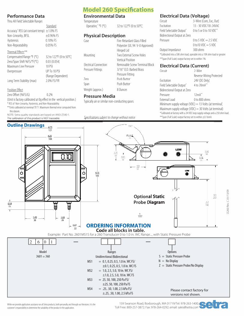
Performance DataThru All Field Selectable Ranges
StandardAccuracy* RSS (at constant temp) ±1.0% FS Non-Linearity, BFSL ±0.96% FS Hysteresis 0.10% FS Non-Repeatability 0.05% FS
Thermal Effects** Compensated Range °F (°C) 32 to 122°F (0 to 50°C)Zero/Span Shift %FS/°F(°C) 0.03 (0.054)Maximum Line Pressure 10 PSIOverpressure UP To 10 PSI (Range Dependent)Long Term Stability (max) 2.0% FS/YR
Position EffectZero Offset (%FS/G) 0.2%(Unit is factory calibrated at 0g effect in the vertical position.) * RSS of Non-Linearity, Hysteresis, and Non-Repeatability.**Units calibrated at nominal 70˚F. Maximum thermal error computed from this datum.
Electrical Data (Voltage)Circuit 3-Wire (Com, Exc, Out)Excitation 13 - 30 VDC/18-24VACField Selectable Output* 0 to 5 or 0 to 10 VDC**
Bidirectional Output at Zero Pressure 0 to 5 VDC = 2.5 VDC 0 to10 VDC = 5 VDCOutput Impedance 300 ohms*Calibrated into a 50K ohm load, operable into a 10K ohm load or greater.
**Span (Full Scale) output factory set to within 1%.
Electrical Data (Current)Circuit 2-Wire Reverse Wiring ProtectedExcitation 24V (DC Only)Field Selectable Output* 4 to 20mA**
Bidirectional Output at ZeroPressure: 12mA**
External Load 0 to 800 ohmsMinimum supply voltage (VDC) = 13 Volts (at terminal)Maximum supply voltage (VDC) = 30 Volts (at terminal)*Calibrated at factory with a 24 VDC loop supply voltage and a 250 ohm load.**Span (Full Scale) output factory set to wtihin ±0.16mA.
Model 260 Specifi cations
159 Swanson Road, Boxborough, MA 01719/Tel: 978-263-1400; Toll Free: 800-257-3872; Fax: 978-264-0292; email: [email protected]
SS26
0 Re
v. C
01/
13/0
9Code all blocks in table.Code all blocks in table.
Example: Part No. 2601MS1S for a 260 Transducer 0 to 1.0 in. WC Range..., with Static Pressure Probe
Model 2601 = 260
Please contact factory for versions not shown.
2 6 0 12 6 0 12 6 0 12 6 0 1
MS1 = 0.1, 0.25, 0.5, 1.0 in. WC FS/ ±0.1, 0.25, 0.5, 1.0 in. WC FS MS2 = 1.0, 2.5, 5.0, 10 in. WC FS/ ±1.0, 2.5, 5.0, 10 in. WC FS MS3 = 25, 50, 100, 250 Pa FS/ ±25, 50, 100, 250 Pa FS MS4 = .25, .50, 1.00, 2.5 kPa FS/ ±.25, .50, 1.00, 2.5 kPa FS
Outline Drawings
RangesRanges Unidirectional/Bidirectional
While we provide application assistance on all Setra products, both personally and through our literature, it is the customer’s responsibility to determine the suitability of the product in the application.
Environmental DataTemperature Operating* °F (°C) 32 to 122°F (0 to 50°C)
Physical DescriptionCase Fire-Retardant Glass Filled Polyester (UL 94 V-0 Approved) Hinged Lid Mounting Two External Screw Holes Vertical Position Electrical Connection Removable Screw Terminal BlockPressure Fittings 3/16” O.D. Barbed Brass Pressure Fitting Zero Push ButtonSpan Push Button
Weight (approx.) 8 Ounces
Pressure MediaTypically air or similar non-conducting gases.
4.75 121
4.25 108
0.5915
1.4938
1.03 26
0.87 22
4.15 105
Specifciations subject to change without notice.Specifciations subject to change without notice.NOTE: Setra quality standards are based on ANSI-Z540-1. The calibration of this product is NIST traceable.The calibration of this product is NIST traceable.
MM IN
1500
1.25 32
0.6316
1.31.332
1.5038
0.510.51 13
Optional Static Optional Static Probe DiagramProbe Diagram
9.3237
7.7 196
O0.8620.862 22
O
ORDERING INFORMATION
Options S = Static Pressure Probe N = No Display Z = Static Pressure Probe/No Display
159 Swanson Road, Boxborough, MA 01719/Tel: 978-263-1400; 159 Swanson Road, Boxborough, MA 01719/Tel: 978-263-1400;

Line and load side terminals accept bus bar connections for reduced costs and more effi cient installation of multiple devices.
Guarded posidrive terminal screws with fi nger-safe protection to IEC 947-1
Trip-free mechanism; device operation cannot be defeated by holding theoperator in the ON position
Color coded indicator provides visual indication of the device status and isolation function
Available in one, two and three pole;one pole + neutral and three pole + neutral
Box lug terminals accept #18…#4(1.0…25mm2) wire as standard
Current limiting and interrupting capacity up to 5kA at 480VAC.
Devices install on standard 35mm DIN-rail (EN 50022)
Magnetic trip elements provideType B, C and D trip characteristics
(IEC and EN 60898), while bimetallic elements protect against slight overloads.
Amp rating and trip curve characteristic clearly marked on the device for easy
identifi cation
Three Trip Broad Range IP20 Protection for Din-rail Characteristics of Currents Accidental Contact Mounted
Bringing you the world’s best products
Sprecher+Schuh Series L8 Supplementary Protectors provide sup ple men tal over cur rent pro tec tion for control circuits, solenoids, ac tu a tors, ap pli anc es, business equip ment and a range
of other ap pli ca tions where a high per for mance current limiting device is required. Ad vanced features and global ap prov als make them ideal for use in equip ment installed through out the world.
Series L8 Supplementary Protectors
ExtendedEnhancedEconomical
L8

Publication No: LIT-F-L8-706 7/06
Sprecher + Schuh US Division Headquarters Sprecher + Schuh Canadian Division15910 International Plaza Dr., Houston, TX 77032 3610 Nashua Dr., Unit 10, Mississauga, Ontario L4V 1L2Tel: (281) 442-9000; Fax: (800) 739-7370 Tel: (905) 677-7514; Fax: (905) 677-7663www.sprecherschuh.com
Three trip characteristics meanmore fl exibilitySprecher + Schuh Series L8 Supplementary Protectors are avail-able with three different tripping characteristics, Type “B”, “C”, and “D.” The tripping characteristic defi nes the device’s speed of response (trip-time) to various levels of over current. The time-current characteristics enable the device to be optimally matched to the application.
Type “B” CharacteristicDeveloped primarily to protect conductors and low level signal devices such as PLCs.
Type “C” CharacteristicDeveloped primarily for applications with moderate inrush currents such as lighting, control circuits and coils, comput-ers and appliances.
Type “D” CharacteristicDeveloped primarily for applications with high inrush cur-rents, i.e., transformers, power supplies and heaters.
Call your Sprecher + Schuh representative for more informationon Series L8 Supplementary Protectors
Broad selection of poles, sizes and accessoriesSeries L8 Supplementary Protectors are available in up to 20 different current ratings from 0.5A to 63A, in one, two and three pole con fi g u ra tions. Over 180 base models are available with a full compliment of accessories.
Global approvals for world wide acceptanceSeries L8 Supplementary Protectors are UL Rec og nized for use in the United States in ac cor dance with NFPA 79 (NEC, Na tion al Elec tri cal Code). The de vic es comply with UL 1077 and CSA 22.2 No.235, meeting the re quire ments for sup ple men ta ry protectors intended for use as over current protection where branch circuit protection is not required, or is provided by an oth er device such as a fuse or mold ed case circuit breaker. These Supplementary Protectors also comply with IEC 60898 for use in com mer cial and res i den tial ap pli ca tions and are CE marked.
Easy installationSprecher+Schuh Supplementary Protectors mount on a stan dard 35mm DIN-rail. Wire terminals accept multiple con duc tors, and bus bars can be used to quickly distribute power to many Supplementary Protectors si mul ta neous ly. In ad di tion, power to the circuit break ers can be fed from the line or load side.
Devices can be used in ap pli ca tions up to 480V AC and 48V DC with in ter rupt ing capacities up to 10kA.
Series L8 L8