submittal transmittal st joseph's hosp - fulton als ... - als/files/submittals/division... ·...
TRANSCRIPT
Standard
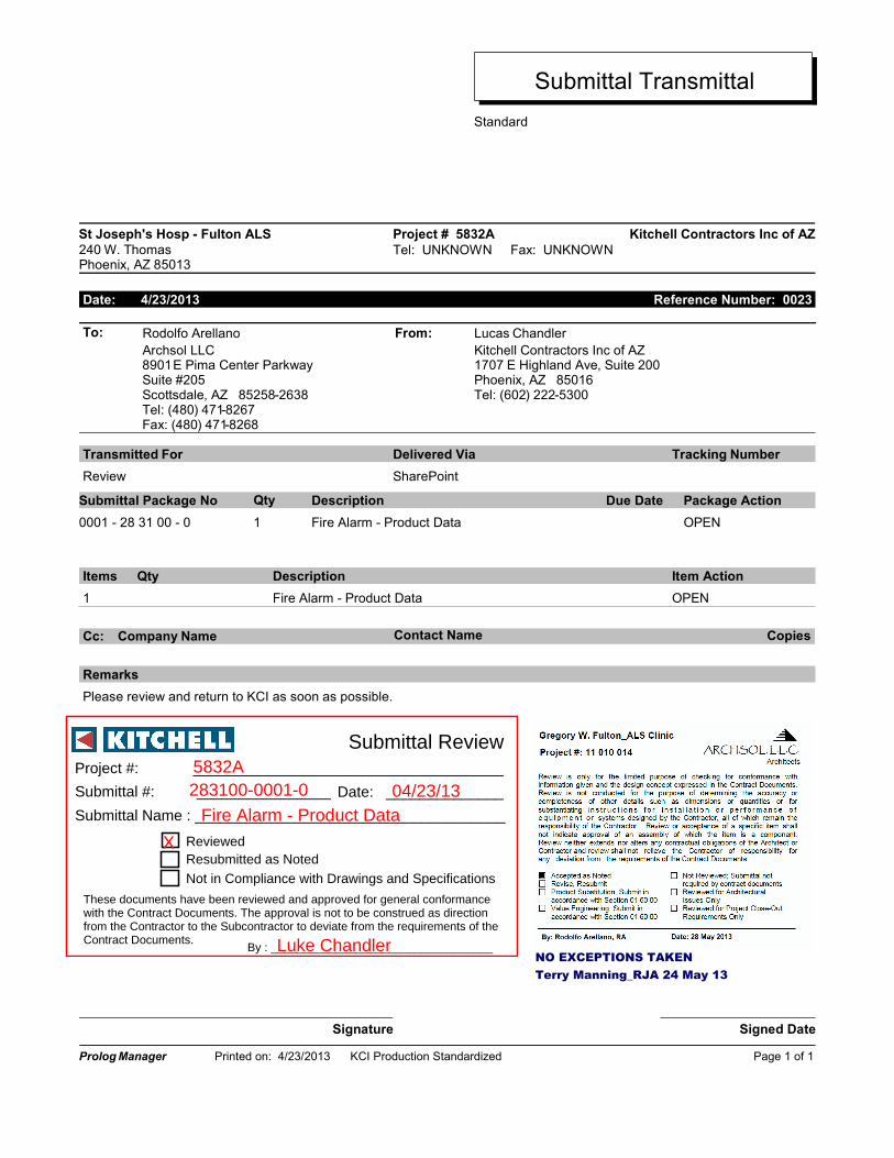
Submittal Transmittal
Kitchell Contractors Inc of AZSt Joseph's Hosp - Fulton ALS Project # 5832A
240 W. ThomasPhoenix, AZ 85013
Tel: UNKNOWN Fax: UNKNOWN
Date: 4/23/2013 Reference Number: 0023
From: Lucas ChandlerRodolfo ArellanoTo:
Archsol LLC Kitchell Contractors Inc of AZ8901 E Pima Center ParkwaySuite #205Scottsdale, AZ 85258-2638Tel: (480) 471-8267Fax: (480) 471-8268
1707 E Highland Ave, Suite 200Phoenix, AZ 85016Tel: (602) 222-5300
Transmitted For Delivered Via Tracking Number
SharePointReview
Submittal Package No Description Due Date Package Action
OPENFire Alarm - Product Data0001 - 28 31 00 - 0
Qty
1
Item ActionItems DescriptionQty
1 Fire Alarm - Product Data OPEN
Contact Name CopiesCompany NameCc:
Remarks
Please review and return to KCI as soon as possible.
Signature Signed Date
Prolog Manager Printed on: 4/23/2013 KCI Production Standardized Page 1 of 1
Date: ______________
Project #: _____________________________________
Submittal #: ________________
Submittal Name : _____________________________________
These documents have been reviewed and approved for general conformance with the Contract Documents. The approval is not to be construed as direction from the Contractor to the Subcontractor to deviate from the requirements of the Contract Documents.
Resubmitted as NotedNot in Compliance with Drawings and Specifications
Submittal Review
By : __________________________________
Reviewed
5832A283100-0001-0 04/23/13
Fire Alarm - Product Data
X
Luke ChandlerNO EXCEPTIONS TAKEN Terry Manning_RJA 24 May 13

Transmittal for Electronic Submittals Project Name: St. Joe’s Medical ALS Date: 4/4/13 Name and address of Architect: Archsol, LLC 8901 East Pima Center Parkway, Suite 205 Scottsdale, AZ 85258 Name of Contractor: Kitchell Name of Firm or Entity that prepared submittal: Jenco, Inc. Name of Subcontractor, manufacturer, and supplier: American Fire Equipment Category and type of submittal: Fire Alarm Submittal purpose and description: For Approval Specification paragraph number or drawing designation and generic name for each of multiple items: Fire Alarm Location where product is to be installed: St. Joseph’s Hospital ALS Indication of full or partial submittal: Full Transmittal Number: 10-13-107-SUB001 Submittal and transmittal distribution record: Uploaded via Sharepoint 4/4/13
7469 E. Monte Cristo Avenue Scottsdale, Arizona 85260
Tel: 480-607-9797 Fax: 480-607-9091
www.jencoinc.com

St. Joes Med ALS
Jen Project #10-13-107
Submittals Fire Alarm
7469 East Monte Cristo Ave Scottsdale, Arizona 85260 Phone (480) 607-9797 Fax (480) 607-9091 Jencoinc.com
Fire Alarm System Modification
Equipment Submittal Package For:
St. Joseph’s Hospital & Medical Center 240 Gregory W. Fulton ALS Clinic
240 West Thomas Road
Phoenix, Arizona 85013
Prepared By:
American Fire Equipment Sales and Service Corporation
3107 West Virginia Avenue
Phoenix, Arizona 85009
Phone (602) 433-2484
Fax (602) 433-9626 www.americanfire.com
Table of Contents
1. Fire Alarm Control Panels, Power Supplies
2. Detection Devices
3. Audio/Visual Devices
4. System Components, Modules and Relays

dn-6927:a • 04/30/09 — Page 1 of 2
FCPS-24S6(C/E) & FCPS-24S8(C/E)6- & 8-Amp 24-VoltRemote Power Supplies
Power Supplies
dn-6927:a
GeneralThe FCPS-24S6E (6-amp) and FCPS-24S8E (8-amp) areremote power supplies with battery charger. The FCPS-24S6/-24S8 may be connected to any 12 or 24 volt fire alarm controlpanel (FACP) or may be used as stand-alone supplies. Pri-mary applications include notification appliance (bell) circuit(NAC) expansion (to support ADA requirements and NAC syn-chronization) or auxiliary power to support 24 volt systemaccessories. The FCPS-24S6/-24S8 provides regulated andfiltered 24 VDC power to four notification appliance circuitsconfigured as either four Class B (Style Y) or Class A (Style Z,with ZNAC-4 option module). Alternately, the four outputs maybe configured as all non-resettable, all resettable or two non-resettable and two resettable. The FCPS-24S6/-24S8 alsocontains a battery charger capable of charging up to 18 AHbatteries. FCPS-24S6C & FCPS-24S8C are ULC-listed.
NOTE: Unless otherwise specified, the terms FCPS-24S6 andFCPS-24S8 used in this document refers to the standard FCPS-24S6 and FCPS-24S8, FCPS-24S6C and FCPS-24S8C, theFCPS-24S6E and FCPS-24S8E
Features• UL-Listed NAC synchronization using System Sensor,
Wheelock, or Gentex “Commander2” appliances.
• Operates as a “sync-follower” or as a “sync-generator”(default). See note on page 2.
• Contains two fully-isolated input/control circuits - triggeredfrom FACP NAC (NAC expander mode) or jumped perma-nently “ON” (stand-alone mode).
• Four Class B (Style Y) or four Class A (Style Z, withZNAC-4 module) NACs.
• 6-amp (FCPS-24S6) or 8-amp (FCPS-24S8) full load out-put, with 3 amps maximum/circuit, in NAC expander mode(UL 864).
• 4-amp (FCPS-24S6) or 6-amp (FCPS-24S8) continuousoutput in stand-alone mode (UL 1481).
• Compatible with coded inputs; signals passed through.
• Optional power-supervision relay (EOLR-1).• In stand-alone mode, output power circuits may be config-
ured as: resettable, (reset line from FACP required),non-resettable, or a mix of two and two.
• Fully regulated and filtered power output - optimal for pow-ering four-wire smoke detectors, annunciators, and othersystem peripherals requiring regulated/filtered power.
• Power-limiting technology meets UL power-limiting require-ments.
• Form-C normally-closed trouble relay.
• Fully supervised power supply, battery, and NACs.• Selectable earth fault detection.• AC trouble report selectable for immediate 2-hour delay.
• Works with virtually any UL 864 fire alarm control which uti-lizes an industry-standard reverse-polarity notification cir-cuit (including unfiltered and unregulated bell power).
• Requires input trigger voltage of 9 - 32 VDC.
• Self-contained in compact, locking cabinet - 15”H x 14.5”Wx 2.75”D (cm: 38.1H x 36.83W x 6.985D).
• Includes integral battery charger capable of charging up to18 AH batteries. Cabinet capable of housing 7.0 AH batter-ies.
• Battery charger may be disabled via DIP switch for applica-tions requiring larger batteries.
• Fixed, clamp-type terminal blocks accommodate up to 12AWG (3.1mm2) wire.
SpecificationsPrimary (AC) Power:
• FCPS-24S6C/-24S8C: 120 VAC, 60 Hz, 3.2A maximum.• FCPS-24S6E/-24S8E: 240 VAC, 50 Hz, 1.6A maximum.
• Wire Size: minimum #14 AWG (2.0mm2) with 600 V insula-tion.
Control Input Circuit:
• Trigger Input Voltage: 9 to 32 VDC.• Trigger Current: 2.0 mA (16 - 32 V); Per Input: 1.0 mA (9
- 16 V).Trouble Contact Rating: 5 A at 24 VDC.
Auxiliary Power Output: Specific application power 500 mAmaximum.
Output Circuits:
• +24 VDC filtered, regulated.• 3.0 A maximum for any one circuit.
• Total continuous current for all outputs (stand-alone mode):– FCPS-24S6: 4.0 A maximum.– FCPS-24S8: 6.0 A maximum.
• Total short-term current for all outputs (NAC expander mode):– FCPS-24S6: 6.0 A maximum.– FCPS-24S8: 8.0 A maximum.
Secondary Power (Battery) Charging Circuit:
• Supports lead-acid batteries only.• Float-charge voltage: 27.6 VDC.
6927pho1.jpg

Page 2 of 2 — dn-6927:a • 04/30/09
System Sensor® and NOTIFIER® are registered trademarks of HoneywellInternational Inc. ©2009 by Honeywell International Inc. All rights reserved. Unauthorized useof this document is strictly prohibited.
This document is not intended to be used for installation purposes. We try to keep our product information up-to-date and accurate.
We cannot cover all specific applications or anticipate all requirements. All specifications are subject to change without notice.
For more information, contact Notifier. Phone: (203) 484-7161, FAX: (203) 484-7118.www.notifier.com
Made in the U.S. A.
• Maximum current charge: 1.5 A.
• Maximum battery capacity: 18 AH.
ApplicationsExample 1: Expand notification appliance power an additional6.0 A (FCPS-24S6) or 8.0 A (FCPS-24S8). Use up to fourClass B (Style Y) outputs or four Class A (Style Z) outputs(using ZNAC-4). For example, the FACP notification appliancecircuits will activate the FCPS when reverse-polarity activationoccurs. Trouble conditions on the FCPS are sensed by theFACP through the notification appliance circuit.
Example 2: Use the FCPS to expand auxiliary regulated 24-volt system power up to 4.0 A (FCPS-24S6) or up to 6.0 A(FCPS-24S8). Both resettable and non-resettable poweroptions are available. Resettable outputs are created by con-necting the resettable output from the FACP to one or both ofthe FCPS inputs.
Example 3: Use addressable control modules to activate theFCPS instead of activating it through the FACP notificationappliance circuits. This typically allows for mounting the FCPSat greater distances* away from the FACP while expandingsystem architecture in various applications.
For example, an addressable control module is used to acti-vate the FCPS, and an addressable monitor module is used tosense FCPS trouble conditions. Local auxiliary power outputfrom the FCPS provides power to the addressable controlmodule.
*NOTE: Addressable FACPs are capable of locating control andmonitor modules at distances of up to 12,500 feet (3,810 meters).
Sync Follower/Generator NoteIn some installations, it is necessary to synchronize the flashtiming of all strobes in the system for ADA compliance.Strobes accomplish this by monitoring very short timing pulseson the NAC power which are created by the FACP. Wheninstalled at the end of a NAC wire run, the FCPS-24S6/-24S8can track (i.e. “follow”) the strobe synchronization timingpulses on the existing NAC wire run. This maintains the overallsystem flash timing of the additional strobes attaches to theFCPS.
When the FCPS-24S6/-24S8 is configured (via DIP switch set-tings) as a “sync follower,” the FCPS’s NAC outputs track thestrobe synchronization pulses present at the FCPS’s syncinput terminal. The pulses originate from an upstream FACP orother power supply.
When the FCPS-24S6/-24S8 are configured (via DIP switchsettings) as a “sync generator,” the FCPS’s sync input termi-nals are not used. Rather, the FCPS is the originator of thestrobe synchronization pulses on the FCPS’s NAC outputs. In“sync generator” mode, the sync type (System Sensor, Whee-lock, or Gentex) is selectable via DIP switch settings.
Standards and CodesThe FCPS-24S6 and FCPS-24S8 comply with the followingstandards:
• NFPA 72 National Fire Alarm Code.• UL 864 Standard for Control Units for Fire Alarm Systems
(NAC expander mode).• UL 1481 Power Supplies for Fire Alarm Systems.
Agency Listings and ApprovalsThese listings and approvals apply to the modules specified inthis document. In some cases, certain modules or applicationsmay not be listed by certain approval agencies, or listing maybe in process. Consult factory for latest listing status.
• UL Listed: S635, S674
• ULC Listed: S635 (FCPS-24S6C & FCPS-24S8C)• CSFM Approved: 7315-0028:225 • MEA: 299-02-E
• FM Approved
Ordering InformationFCPS-24S6: 6.0 A, 120 VAC remote charger power supply.Includes main printed circuit board, transformers, enclosure(15”H x 14.5”W x 2.75”D [cm: 38.1H x 36.83W x 6.985D]), andinstallation instructions.
FCPS-24S6C: Same as above, ULC-listed.
FCPS-24S6R: Same as FCPS-24S6 with red enclosure.
FCPS-24S6E: 6.0 A, 240 VAC remote charger power supply.Includes main printed circuit board, transformers, enclosure(15”H x 14.5”W x 2.75”D [cm: 38.1H x 36.83W x 6.985D]), andinstallation instructions.
FCPS-24S8: 8.0 A, 120 VAC remote charger power supply.Includes main printed circuit board, transformers, enclosure(15”H x 14.5”W x 2.75”D [cm: 38.1H x 36.83W x 6.985D]), andinstallation instructions.
FCPS-24S8C Same as above, ULC-listed.
FCPS-24S8R: Same as FCPS-24S8 with red enclosure.
FCPS-24S8E: 8.0 A, 240 VAC remote charger power supply.Includes main printed circuit board, transformers, enclosure(15”H x 14.5”W x 2.75”D [cm: 38.1H x 36.83W x 6.985D]), andinstallation instructions.
ZNAC-4: Class A (Style Y) NAC option module.
EOLR-1: 12/24 VDC end-of-line relay for monitoring four-wiresmoke detector power.
BAT-1270: Battery, 12-volt, 7.0 AH (two required, see BATSeries data sheet DN-6933).
PS-1270: Battery, 12-volt, 7.0 AH (two required, see PSSeries data sheet DN-1109)
FSP-851(A) SeriesIntelligent Plug-In PhotoelectricSmoke Detectors with FlashScan®
Intelligent/Addressable Devices
DN-6935:D • H-202
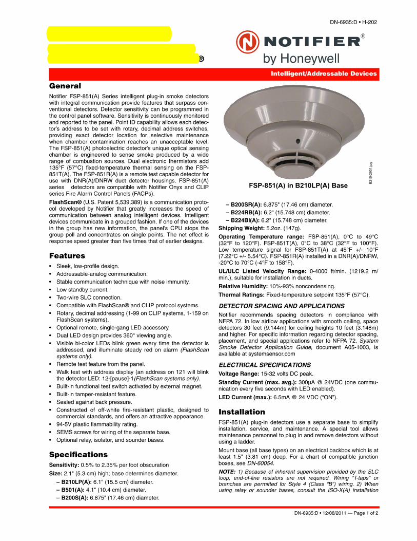
GeneralNotifier FSP-851(A) Series intelligent plug-in smoke detectors with integral communication provide features that surpass con-ventional detectors. Detector sensitivity can be programmed in the control panel software. Sensitivity is continuously monitored and reported to the panel. Point ID capability allows each detec-tor’s address to be set with rotary, decimal address switches, providing exact detector location for selective maintenance when chamber contamination reaches an unacceptable level. The FSP-851(A) photoelectric detector’s unique optical sensing chamber is engineered to sense smoke produced by a wide range of combustion sources. Dual electronic thermistors add 135°F (57°C) fixed-temperature thermal sensing on the FSP-851T(A). The FSP-851R(A) is a remote test capable detector for use with DNR(A)/DNRW duct detector housings. FSP-851(A) series detectors are compatible with Notifier Onyx and CLIP series Fire Alarm Control Panels (FACPs).
FlashScan® (U.S. Patent 5,539,389) is a communication proto-col developed by Notifier that greatly increases the speed of communication between analog intelligent devices. Intelligent devices communicate in a grouped fashion. If one of the devices in the group has new information, the panel’s CPU stops the group poll and concentrates on single points. The net effect is response speed greater than five times that of earlier designs.
Features• Sleek, low-profile design.• Addressable-analog communication.• Stable communication technique with noise immunity.• Low standby current.• Two-wire SLC connection.• Compatible with FlashScan® and CLIP protocol systems. • Rotary, decimal addressing (1-99 on CLIP systems, 1-159 on
FlashScan systems).• Optional remote, single-gang LED accessory.• Dual LED design provides 360° viewing angle.• Visible bi-color LEDs blink green every time the detector is
addressed, and illuminate steady red on alarm (FlashScan systems only).
• Remote test feature from the panel.• Walk test with address display (an address on 121 will blink
the detector LED: 12-[pause]-1(FlashScan systems only).• Built-in functional test switch activated by external magnet.• Built-in tamper-resistant feature.• Sealed against back pressure.• Constructed of off-white fire-resistant plastic, designed to
commercial standards, and offers an attractive appearance.• 94-5V plastic flammability rating.• SEMS screws for wiring of the separate base.• Optional relay, isolator, and sounder bases.
SpecificationsSensitivity: 0.5% to 2.35% per foot obscuration
Size: 2.1" (5.3 cm) high; base determines diameter.
– B210LP(A): 6.1" (15.5 cm) diameter.– B501(A): 4.1" (10.4 cm) diameter.– B200S(A): 6.875" (17.46 cm) diameter.
– B200SR(A): 6.875" (17.46 cm) diameter. – B224RB(A): 6.2" (15.748 cm) diameter. – B224BI(A): 6.2" (15.748 cm) diameter.
Shipping Weight: 5.2oz. (147g).
Operating Temperature range: FSP-851(A), 0°C to 49°C (32°F to 120°F). FSP-851T(A), 0°C to 38°C (32°F to 100°F). Low temperature signal for FSP-851T(A) at 45°F +/- 10°F (7.22°C +/- 5.54°C). FSP-851R(A) installed in a DNR(A)/DNRW, -20°C to 70°C (-4°F to 158°F).
UL/ULC Listed Velocity Range: 0-4000 ft/min. (1219.2 m/min.), suitable for installation in ducts.
Relative Humidity: 10%-93% noncondensing.
Thermal Ratings: Fixed-temperature setpoint 135°F (57°C).
DETECTOR SPACING AND APPLICATIONS
FSP-851(A) in B210LP(A) Base B21
0-2
951.
jpg
Notifier recommends spacing detectors in compliance with NFPA 72. In low airflow applications with smooth ceiling, space detectors 30 feet (9.144m) for ceiling heights 10 feet (3.148m) and higher. For specific information regarding detector spacing, placement, and special applications refer to NFPA 72. System Smoke Detector Application Guide, document A05-1003, is available at systemsensor.com
ELECTRICAL SPECIFICATIONSVoltage Range: 15-32 volts DC peak.
Standby Current (max. avg.): 300μA @ 24VDC (one commu-nication every five seconds with LED enabled).
LED Current (max.): 6.5mA @ 24 VDC (“ON”).
InstallationFSP-851(A) plug-in detectors use a separate base to simplify installation, service, and maintenance. A special tool allows maintenance personnel to plug in and remove detectors without using a ladder.
Mount base (all base types) on an electrical backbox which is at least 1.5" (3.81 cm) deep. For a chart of compatible junction boxes, see DN-60054.
NOTE: 1) Because of inherent supervision provided by the SLC loop, end-of-line resistors are not required. Wiring “T-taps” or branches are permitted for Style 4 (Class “B”) wiring. 2) When using relay or sounder bases, consult the ISO-X(A) installation
DN-6935:D • 12/08/2011 — Page 1 of 2

-Notifier® and FlashScan® are registered trademarks of Honeywell International Inc.©2011 by Honeywell International Inc. All rights reserved. Unauthorized use of this document is strictly prohibited.
sheet I56-1380 for device limitations between isolator modules and isolator bases.
Agency Listings and ApprovalsThese listings and approvals apply to the modules specified in this document. In some cases, certain modules or applications may not be listed by certain approval agencies, or listing may be in process. Consult factory for latest listing status.
• UL Listed: S1115. • ULC Listed: S1115 (FSP-851A, FSP-851RA, FSP-851TA). • MEA Listed: 225-02-E .• FM Approved.• CSFM: 7272-0028:0206 .• Maryland State Fire Marshal: Permit # 2122 .• BSMI: CI313066760036.• CCCF: Certif. # 2004081801000017 (FSP-851T)
Certif. # 2004081801000016 (FSP-851).• U.S. Coast Guard: 161.002/42/1 (NFS-640); 161.002/50/0
(NFS2-640/NFS-320/NFS-320C, excluding B210LP(A)).• Lloyd’s Register: 11/600013 (NFS2-640/NFS-320/NFS-
320C, excluding B210LP(A)).
Product Line InformationNOTE: “A” suffix indicates ULC Listed model.
FSP-851: Low-profile intelligent photoelectric sensor. Must be mounted to one of the bases listed below.
FSP-851A: Same as FSP-851 but with ULC listing.
FSP-851T: Same as FSP-851 but includes a built-in 135°F (57°C) fixed-temperature thermal device.
FSP-851TA: Same as FSP-851T but with ULC listing.
FSP-851R: Low-profile intelligent photoelectric sensor, remote test capable. For use with DNRA/DNRW.
FSP-851RA: Same as FSP-851R but with ULC listing. For use with DNRA.
INTELLIGENT BASESNOTE: “A” suffix indicates ULC Listed model.
NOTE: For details on intelligent bases, see DN-60054.
B210LP(A): Standard U.S. flanged low-profile mounting base.
B210LPBP: Bulk pack of B210LP; package contains 10.
B501(A): Standard European flangeless mounting base.
B501BP: Bulk pack of B501; package contains 10.
B200S(A): Intelligent, programmable sounder base capable of producing sound output in high or low volume with ANSI Tempo-ral 3, ANSI Temporal 4, continuous tone, marching tone, and custom tone.
B200SR(A): Intelligent sounder base capable of producing sound output with ANSI Temporal 3 or continuous tone. Replaces B501BH series bases in retrofit applications.
B224RB(A): Plug-in System Sensor relay base. Screw termi-nals: up to 14 AWG (2.0 mm²). Relay type: Form-C. Rating: 2.0 A @ 30 VDC resistive; 0.3 A @ 110 VDC inductive; 1.0 A @ 30 VDC inductive.
B224BI(A): Plug-in System Sensor isolator detector base. Maximum 25 devices between isolator bases .
ACCESSORIESF110: Retrofit flange to convert B210LP(A) to match the B710LP(A) profile, or to convert older high-profile bases to low-profile.
F110BP: Bulk pack of F110; package contains 15.
F210: Replacement flange for B210LP(A) base.
RA100Z(A): Remote LED annunciator. 3 – 32 VDC. Mounts to a U.S. single-gang electrical box. For use with B501(A) and B210LP(A) bases only.
SMB600: Surface mounting kit
M02-04-00:Test magnet.
M02-09-00: Test magnet with telescoping handle.
XR2B: Detector removal tool. Allows installation and/or removal of detector heads from bases in high ceiling applications.
XP-4: Extension pole for XR2B. Comes in three 5-foot (1.524 m) sections.
T55-127-010: Detector removal tool without pole.
BCK-200B: Black detector covers for use with FSP-851(A) only; box of 10.
WCK-200B: White detector covers for use with FSP-851(A)only; box of 10.
Page 2 of 2 — DN-6935:D • 12/08/2011
This document is not intended to be used for installation purposes. We try to keep our product information up-to-date and accurate.
We cannot cover all specific applications or anticipate all requirements. All specifications are subject to change without notice.
For more information, contact Notifier. Phone: (203) 484-7161, FAX: (203) 484-7118.www.notifier.com
Made in the U.S. A.

DN-60429:C1 • 4/19/2012 — Page 1 of 2
DNR(A)/DNRW InnovairFlexIntelligent Non-Relay Photoelectric Duct Smoke Detector
Intelligent Devices
DN-60429:C1
GeneralThe Notifier InnovairFlex® DNR(A) intelligent non-relay photo-electric duct smoke detector and DNRW watertight non-relayphotoelectric duct smoke detector feature a pivoting housingthat fits both square and rectangular footprints capable ofmounting to a round or rectangular duct.
DNRW duct smoke detector, with its NEMA-4 rating, is listedas a watertight, UV resistant enclosure providing protectionagainst falling dirt, rain, and windblown dust, splashing andhose directed water, allowing operators to use the detector inthe most extreme environments.
These units sense smoke in the most challenging conditions,operating in airflow speeds of 100 to 4,000 feet per minute (0.5to 20.32 m/s), temperatures of -4°F to 158°F (-20°C to 70°C),and a humidity range of 0 to 95 percent (non-condensing.)
An improved cover design isolates the sensor head, whichallows for ease of maintenance. A cover tamper feature indi-cates a trouble signal for a removed or improperly installedsensor cover. The Notifier InnovairFlex housing provides a 3/4-inch conduit knockout and ample space to facilitate easy wir-ing and mounting of a relay module.
The Notifier InnovairFlex duct smoke detector can be custom-ized to meet local codes and specifications without additionalwiring. The new InnovairFlex product line is compatible with allprevious Innovair models, including remote test accessories.
Features• Photoelectric, integrated low-flow technology.• Air velocity rating from 100 ft/min to 4,000 ft/min (0.5 m/s to
20.32 m/s).• Versatile mounting options: square or rectangular configu-
ration.• Broad ranges for operating temperature (-4°F to 158°F, -
20°C to 70°C) and humidity (0% to 95% non-condensing).• Patented sampling tube installs from front or back of the
detector with no tools required.• Cover tamper signal.
• Increased wiring space with a newly added 3/4” conduitknockout.
• Available space within housing to accommodate mountingof a relay module.
• Easily accessible code wheels on sensor head (sold sepa-rately).
• Clear cover for convenient visual inspection.• Remote testing capability.• Requires com line power only.
• Accommodates the installation of an addressable relaymodule, sold separately, (FRM-1 or NC-100R) for applica-tions requiring a Form-C relay.
SpecificationsSize: (Rectangle) 14.38 in (37 cm) Length; 5 in (12.7 cm)Width, 2.5 in (6.6 cm) Depth.
Size: (Square) 7.75 in (19.7 cm) Length; 9 in (22.9 cm) Width;2.5 in (6.35 cm) Depth.
Weight: 1.6 lb (0.73 kg).
Operating Temperature Range: -4°F to 158°F (-20°C to70°C).
Storage Temperature Range: -22°F to 158°F (-30°C to70°C).
Operating Humidity Range: 0% to 95% relative humidity(non-condensing).
Air Duct Velocity: 100 to 4,000 ft/min (0.5 to 20.32 m/s).
AccessoriesNotifier provides system flexibility with a variety of accessories,including two remote test stations and different means of visi-ble and audible system annunciation. As with our duct smokedetectors, all duct smoke detectors accessories are UL listed.
DNR(W)s with a date code of 0013 or higher do not requireexternal 24VDC for remote test applications when used with aremote-test-capable detector.
ACCESSORY CURRENT LOADS AT 24 VDC
Agency Listings and Approvals Consult product manual for lists of compatible UL-Listeddevices. In some cases, certain modules may not be listed bycertain approval agencies, or listing may be in process. Con-sult factory for latest listing status.
• UL: S911, S3705.• ULC: S635.
Device Standby Alarm
RA100Z 0mA 12 mA Max
RTS151/RTS151KEY
0mA 12mA Max
intelligent innovair-

Page 2 of 2 — DN-60429:C1 • 4/19/2012
Notifier® and FlashScan® are a registered trademark of HoneywellInternational Inc. ©2012 by Honeywell International Inc. All rights reserved. Unauthorized useof this document is strictly prohibited.
This document is not intended to be used for installation purposes. We try to keep our product information up-to-date and accurate.
We cannot cover all specific applications or anticipate all requirements. All specifications are subject to change without notice.
For more information, contact Notifier. Phone: (203) 484-7161, FAX: (203) 484-7118.www.notifier.com
Made in the U.S. A.
• CSFM: 3242-1653:0209.
• FM approved.
Product Line InformationNOTE: “A suffix indicates ULC listed model.
DNR(A): Intelligent non-relay photoelectric low flow smokedetector housing. Requires photoelectric smoke detector (soldseparately).
DNRW: Watertight intelligent non-relay photoelectric low flowduct smoke detector housing. Requires photoelectric smokedetector (sold separately).
FSP-851R(A): Remote test capable addressable low-profilephotoelectric smoke detector.
FSP-851(A): Addressable low-profile photoelectric smokedetector.
NP-100: Addressable low-profile photoelectric smoke detectorfor FireWarden series panels.
NP-100R(A): Remote test capable addressable low-profilephotoelectric smoke detector for FireWarden series panels.
DCOIL: Remote test coil. Required for older DNR(W) ductdetector housing.
DST1(A): Metal sampling tube duct width up to 1 ft (0.3m).
DST1.5(A): Metal sampling tube duct widths up to 1 ft to 2 ft(0.3 to 0.6 m).
DST3(A): Metal sampling tube duct widths up to 2 ft to 4 ft (0.6to 1.2 m).
DST5(A): Metal sampling tube duct widths up to 4 ft to 8 ft (1.2to 2.4 m).
DST10(A): Metal sampling tube duct widths up to 8 ft to 12 ft(2.4 to 3.7 m).
DH400OE-1: Weatherproof enclosure.
ETX: Metal exhaust tube duct, width 1 ft (0.3 m).
M02-04-00: Test magnet.
P48-21-00: End cap for metal sampling tubes.
RA100Z(A): Remote annunciator alarm LED.
RTS151(A): Remote test station.
RTS151KEY(A): Remote test station with key lock.
Important Note• DNRW duct detector housings with a date code of 0013 or
higher do not require a DCOIL or auxiliary 24 VDC forremote test applications when used with a remote testcapable detector.
• DNRW duct detector housings with a date code of 0012 orearlier require a DCOIL and auxiliary 24 VDC power forremote test applications.

Agency Listings
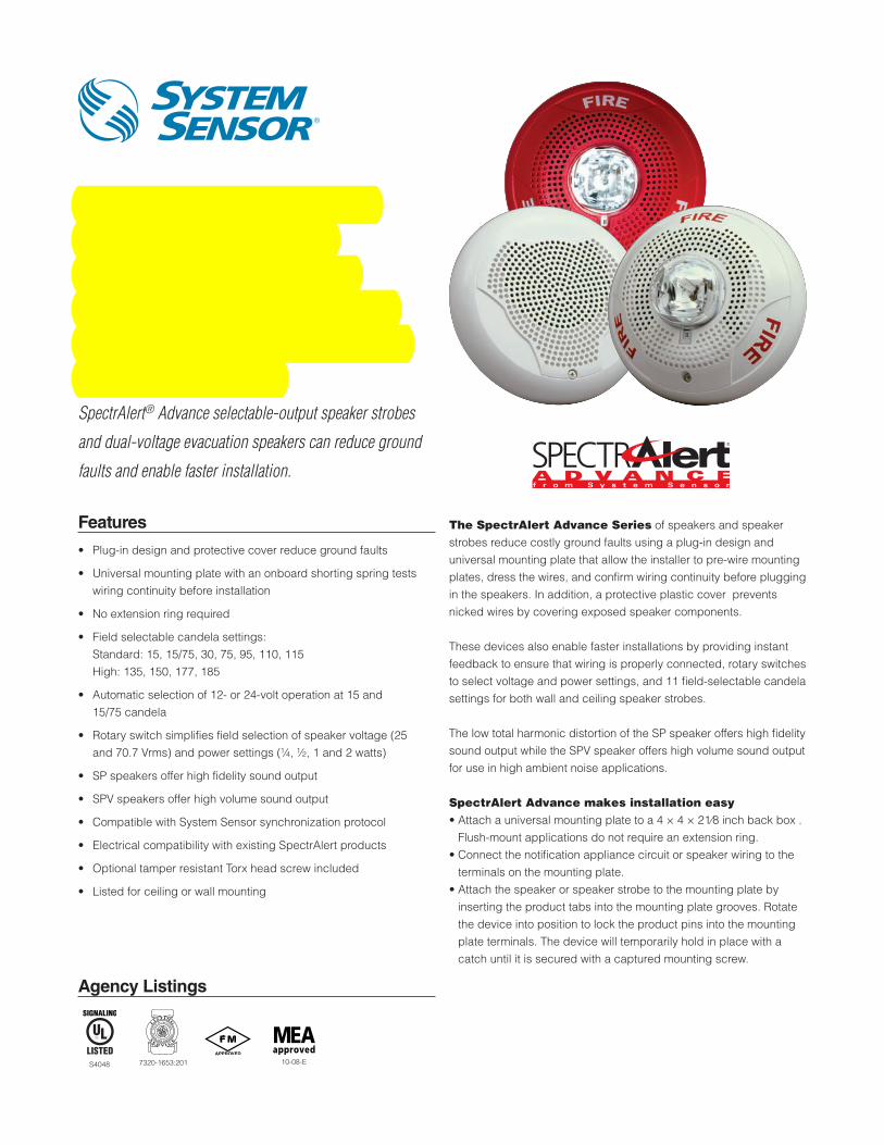
Indoor Selectable- Output Speaker Strobes and Dual Voltage Evacuation Speakers for WallApplicationsThe SpectrAlert® Advance selectable output speaker
strobes and dual-voltage evacuation speakers can reduce
ground faults and enable faster installation.
Features
• Plug-in design and protective cover reduce ground faults
• Universal mounting plate with an onboard shorting spring tests wiring continuity before installation
• No extension ring required
• Field selectable candela settings: Standard: 15, 15/75, 30, 75, 95, 110, 115 High: 135, 150, 177, 185
• Automatic selection of 12- or 24-volt operation at 15 and 15/75 candela
• Rotary switch simplifies field selection of speaker voltage (25 and 70.7 Vrms) and power settings (¼, ½, 1 and 2 watts)
• SP speakers offer high fidelity sound output
• SPV speakers offer high volume sound output
• Compatible with System Sensor synchronization protocol
• Electrical compatibility with existing SpectrAlert products
• Optional tamper resistant Torx head screw included
• Listed for ceiling or wall mounting
The SpectrAlert Advance Series of speakers and speaker strobes reduce costly ground faults using a plug-in design and universal mounting plate that allow the installer to pre-wire mounting plates, dress the wires, and confirm wiring continuity before plugging in the speakers. In addition, a protective plastic cover prevents nicked wires by covering exposed speaker components.
These devices also enable faster installations by providing instant feedback to ensure that wiring is properly connected, rotary switches to select voltage and power settings, and 11 field-selectable candela settings for both wall and ceiling speaker strobes.
The low total harmonic distortion of the SP speaker offers high fidelity sound output while the SPV speaker offers high volume sound output for use in high ambient noise applications.
SpectrAlert Advance makes installation easy• Attach a universal mounting plate to a 4 × 4 × 21⁄8 inch back box .
Flush-mount applications do not require an extension ring.• Connect the notification appliance circuit or speaker wiring to the
terminals on the mounting plate.• Attach the speaker or speaker strobe to the mounting plate by
inserting the product tabs into the mounting plate grooves. Rotate the device into position to lock the product pins into the mounting plate terminals. The device will temporarily hold in place with a catch until it is secured with a captured mounting screw.
10-08-E7320-1653:201S4048
AVDS00801
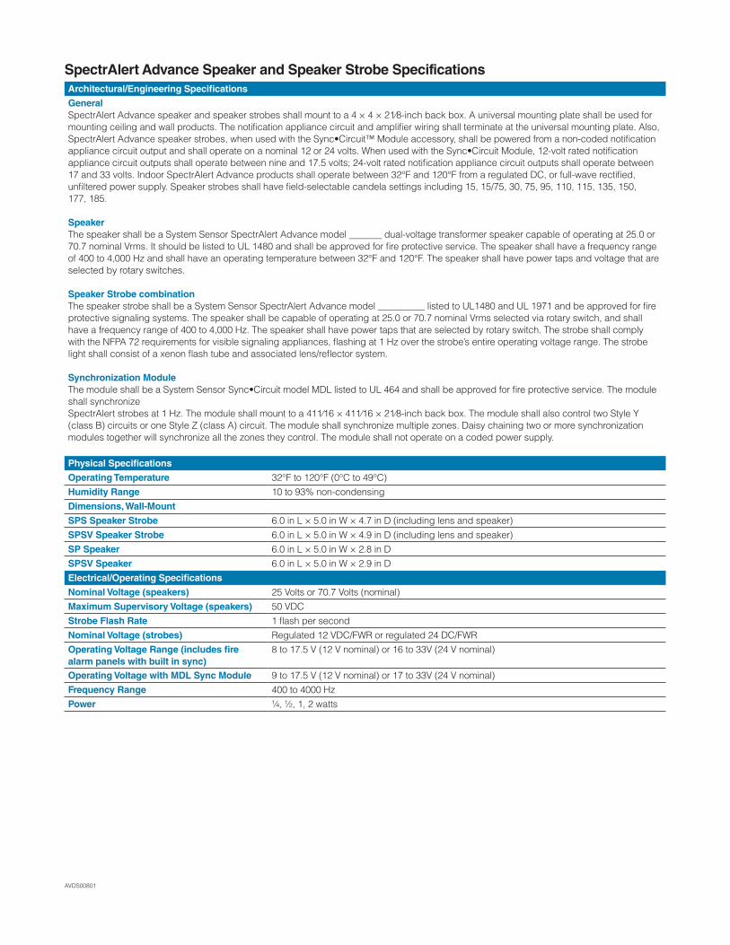
SpectrAlert Advance Speaker and Speaker Strobe SpecificationsArchitectural/Engineering Specifications
GeneralSpectrAlert Advance speaker and speaker strobes shall mount to a 4 × 4 × 21⁄8-inch back box. A universal mounting plate shall be used for mounting ceiling and wall products. The notification appliance circuit and amplifier wiring shall terminate at the universal mounting plate. Also, SpectrAlert Advance speaker strobes, when used with the Sync•Circuit™ Module accessory, shall be powered from a non-coded notification appliance circuit output and shall operate on a nominal 12 or 24 volts. When used with the Sync•Circuit Module, 12-volt rated notification appliance circuit outputs shall operate between nine and 17.5 volts; 24-volt rated notification appliance circuit outputs shall operate between 17 and 33 volts. Indoor SpectrAlert Advance products shall operate between 32°F and 120°F from a regulated DC, or full-wave rectified, unfiltered power supply. Speaker strobes shall have field-selectable candela settings including 15, 15/75, 30, 75, 95, 110, 115, 135, 150,177, 185.
SpeakerThe speaker shall be a System Sensor SpectrAlert Advance model _______ dual-voltage transformer speaker capable of operating at 25.0 or 70.7 nominal Vrms. It should be listed to UL 1480 and shall be approved for fire protective service. The speaker shall have a frequency range of 400 to 4,000 Hz and shall have an operating temperature between 32°F and 120°F. The speaker shall have power taps and voltage that are selected by rotary switches.
Speaker Strobe combinationThe speaker strobe shall be a System Sensor SpectrAlert Advance model __________ listed to UL1480 and UL 1971 and be approved for fire protective signaling systems. The speaker shall be capable of operating at 25.0 or 70.7 nominal Vrms selected via rotary switch, and shall have a frequency range of 400 to 4,000 Hz. The speaker shall have power taps that are selected by rotary switch. The strobe shall comply with the NFPA 72 requirements for visible signaling appliances, flashing at 1 Hz over the strobe’s entire operating voltage range. The strobe light shall consist of a xenon flash tube and associated lens/reflector system.
Synchronization ModuleThe module shall be a System Sensor Sync•Circuit model MDL listed to UL 464 and shall be approved for fire protective service. The module shall synchronizeSpectrAlert strobes at 1 Hz. The module shall mount to a 411⁄16 × 411⁄16 × 21⁄8-inch back box. The module shall also control two Style Y (class B) circuits or one Style Z (class A) circuit. The module shall synchronize multiple zones. Daisy chaining two or more synchronization modules together will synchronize all the zones they control. The module shall not operate on a coded power supply.
Physical Specifications
Operating Temperature 32°F to 120°F (0°C to 49°C)Humidity Range 10 to 93% non-condensingDimensions, Wall-Mount
SPS Speaker Strobe 6.0 in L × 5.0 in W × 4.7 in D (including lens and speaker)SPSV Speaker Strobe 6.0 in L × 5.0 in W × 4.9 in D (including lens and speaker)SP Speaker 6.0 in L × 5.0 in W × 2.8 in DSPSV Speaker 6.0 in L × 5.0 in W × 2.9 in DElectrical/Operating Specifications
Nominal Voltage (speakers) 25 Volts or 70.7 Volts (nominal)Maximum Supervisory Voltage (speakers) 50 VDCStrobe Flash Rate 1 flash per secondNominal Voltage (strobes) Regulated 12 VDC/FWR or regulated 24 DC/FWROperating Voltage Range (includes fire alarm panels with built in sync)
8 to 17.5 V (12 V nominal) or 16 to 33V (24 V nominal)
Operating Voltage with MDL Sync Module 9 to 17.5 V (12 V nominal) or 17 to 33V (24 V nominal)Frequency Range 400 to 4000 HzPower ¼, ½, 1, 2 watts
AVDS00801
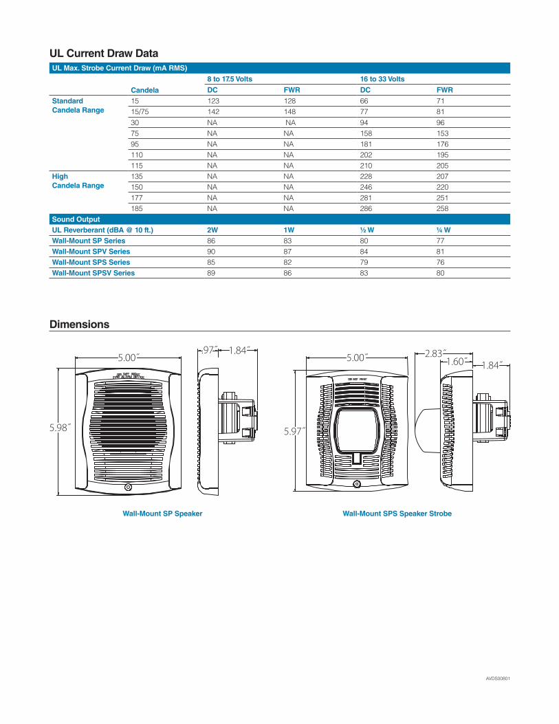
UL Current Draw DataUL Max. Strobe Current Draw (mA RMS)
Candela
8 to 17.5 Volts 16 to 33 Volts
DC FWR DC FWR
StandardCandela Range
15 123 128 66 7115/75 142 148 77 8130 NA NA 94 9675 NA NA 158 15395 NA NA 181 176110 NA NA 202 195115 NA NA 210 205
HighCandela Range
135 NA NA 228 207150 NA NA 246 220177 NA NA 281 251185 NA NA 286 258
Sound OutputUL Reverberant (dBA @ 10 ft.) 2W 1W ½ W ¼ WWall-Mount SP Series 86 83 80 77Wall-Mount SPV Series 90 87 84 81Wall-Mount SPS Series 85 82 79 76Wall-Mount SPSV Series 89 86 83 80
Dimensions
5.00˝.97˝ 1.84˝
5.98˝
5.00˝ 2.83˝1.84˝1.60˝
5.97˝
Wall-Mount SP Speaker Wall-Mount SPS Speaker Strobe

3825 Ohio Avenue • St. Charles, IL 60174 Phone: 800-SENSOR2 • Fax: 630-377-6495
©2012 System Sensor.Product specifications subject to change without notice. Visit systemsensor.com
for current product information, including the latest version of this data sheet.AVDS00801 • 3/12
Ordering Information for SpectrAlert® Advance Speakers and Speaker StrobesWall MountWhite Red DescriptionSPW SPR Speaker onlySPWV SPRV Speaker only, High dBSPSW* SPSR* Speaker Strobe, Standard cdSPSW-ALERT — Speaker Strobe, Standard cd, Amber LensSPSW-CLR-ALERT — Speaker Strobe, Standard cd, Clear LensSPSWH* SPSRH* Speaker Strobe, High cdSPSWV* SPSRV* Speaker Strobe, Standard cd, High dBAccessoriesWhite Red DescriptionRFPW RFP 7 in × 9.5 in Retrofit PlateSPBBSW SPBBS Wall Mount Back Box SkirtTRW TR Wall Mount Trim Ring
Notes:* Add -P to model number for plain housing (no “FIRE” marking on the cover) e.g. SPSW-P‡ “Standard cd” refers to strobes that include 15, 15/75, 30, 75, 95, 110, and 115 candela settings. “High cd” refers to strobes that include 135, 150, 177, and 185 candela settings.
Surface Mounting
Wall-Mount Speaker Strobe with SPBBS Back
Agency Listings
Indoor Selectable-Output Speaker Strobes and Dual Voltage Evacuation Speakers for Ceiling ApplicationsSpectrAlert® Advance selectable-output speaker strobes
and dual-voltage evacuation speakers can reduce ground
faults and enable faster installation.
Features
• Plug-in design and protective cover reduce ground faults
• Universal mounting plate with an onboard shorting spring tests wiring continuity before installation
• No extension ring required
• Field selectable candela settings: Standard: 15, 15/75, 30, 75, 95, 110, 115 High: 135, 150, 177, 185
• Automatic selection of 12- or 24-volt operation at 15 and 15/75 candela
• Rotary switch simplifies field selection of speaker voltage (25 and 70.7 Vrms) and power settings (¼, ½, 1 and 2 watts)
• SP speakers offer high fidelity sound output
• SPV speakers offer high volume sound output
• Compatible with System Sensor synchronization protocol
• Electrical compatibility with existing SpectrAlert products
• Optional tamper resistant Torx head screw included
• Listed for ceiling or wall mounting
The SpectrAlert Advance Series of speakers and speaker strobes reduce costly ground faults using a plug-in design and universal mounting plate that allow the installer to pre-wire mounting plates, dress the wires, and confirm wiring continuity before plugging in the speakers. In addition, a protective plastic cover prevents nicked wires by covering exposed speaker components.
These devices also enable faster installations by providing instant feedback to ensure that wiring is properly connected, rotary switches to select voltage and power settings, and 11 field-selectable candela settings for both wall and ceiling speaker strobes.
The low total harmonic distortion of the SP speaker offers high fidelity sound output while the SPV speaker offers high volume sound output for use in high ambient noise applications.
SpectrAlert Advance makes installation easy• Attach a universal mounting plate to a 4 × 4 × 21⁄8 inch back box .
Flush-mount applications do not require an extension ring.• Connect the notification appliance circuit or speaker wiring to the
terminals on the mounting plate.• Attach the speaker or speaker strobe to the mounting plate by
inserting the product tabs into the mounting plate grooves. Rotate the device into position to lock the product pins into the mounting plate terminals. The device will temporarily hold in place with a catch until it is secured with a captured mounting screw.
10-08-E7320-1653:201S4048

AVDS00701
SpectrAlert Advance Speaker and Speaker Strobe SpecificationsArchitectural/Engineering Specifications
GeneralSpectrAlert Advance speaker and speaker strobes shall mount to a 4 × 4 × 21⁄8-inch back box. A universal mounting plate shall be used for mounting ceiling and wall products. The notification appliance circuit and amplifier wiring shall terminate at the universal mounting plate. Also, SpectrAlert Advance speaker strobes, when used with the Sync•Circuit™ Module accessory, shall be powered from a non-coded notification appliance circuit output and shall operate on a nominal 12 or 24 volts. When used with the Sync•Circuit Module, 12-volt rated notification appliance circuit outputs shall operate between nine and 17.5 volts; 24-volt rated notification appliance circuit outputs shall operate between 17 and 33 volts. Indoor SpectrAlert Advance products shall operate between 32°F and 120°F from a regulated DC, or full-wave rectified, unfiltered power supply. Speaker strobes shall have field-selectable candela settings including 15, 15/75, 30, 75, 95, 110, 115, 135, 150,177, 185.
SpeakerThe speaker shall be a System Sensor SpectrAlert Advance model _______ dual-voltage transformer speaker capable of operating at 25.0 or 70.7 nominal Vrms. It should be listed to UL 1480 and shall be approved for fire protective service. The speaker shall have a frequency range of 400 to 4,000 Hz and shall have an operating temperature between 32°F and 120°F. The speaker shall have power taps and voltage that are selected by rotary switches.
Speaker Strobe combinationThe speaker strobe shall be a System Sensor SpectrAlert Advance model __________ listed to UL1480 and UL 1971 and be approved for fire protective signaling systems. The speaker shall be capable of operating at 25.0 or 70.7 nominal Vrms selected via rotary switch, and shall have a frequency range of 400 to 4,000 Hz. The speaker shall have power taps that are selected by rotary switch. The strobe shall comply with the NFPA 72 requirements for visible signaling appliances, flashing at 1 Hz over the strobe’s entire operating voltage range. The strobe light shall consist of a xenon flash tube and associated lens/reflector system.
Synchronization ModuleThe module shall be a System Sensor Sync•Circuit model MDL listed to UL 464 and shall be approved for fire protective service. The module shall synchronizeSpectrAlert strobes at 1 Hz. The module shall mount to a 411⁄16 × 411⁄16 × 21⁄8-inch back box. The module shall also control two Style Y (class B) circuits or one Style Z (class A) circuit. The module shall synchronize multiple zones. Daisy chaining two or more synchronization modules together will synchronize all the zones they control. The module shall not operate on a coded power supply.
Physical Specifications
Operating Temperature 32°F to 120°F (0°C to 49°C)Humidity Range 10 to 93% non-condensingDimensions, Ceiling-Mount
SPS Speaker Strobe 6.8 in Dia. × 4.7 in D (including lens and speaker)SPSV Speaker Strobe 6.8 in Dia. × 4.8 in D (including lens and speaker)SP Speaker 6.8 in Dia. × 2.8 in DSPV Speaker 6.8 in Dia. × 2.9 in DElectrical/Operating Specifications
Nominal Voltage (speakers) 25 Volts or 70.7 Volts (nominal)Maximum Supervisory Voltage (speakers) 50 VDCStrobe Flash Rate 1 flash per secondNominal Voltage (strobes) Regulated 12 V DC/FWR or regulated 24 DC/FWROperating Voltage Range (includes fire alarm panels with built in sync)
8 to 17.5 V (12 V nominal) or 16 to 33 V (24 V nominal)
Operating Voltage with MDL Sync Module 9 to 17.5 V (12 V nominal) or 17 to 33 V (24 V nominal)Frequency Range 400 to 4,000 HzPower ¼, ½, 1, 2 watts
AVDS00701
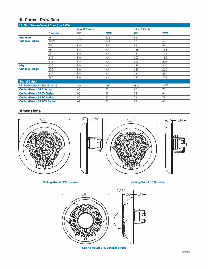
UL Current Draw DataUL Max. Strobe Current Draw (mA RMS)
Candela
8 to 17.5 Volts 16 to 33 Volts
DC FWR DC FWR
StandardCandela Range
15 123 128 66 7115/75 142 148 77 8130 NA NA 94 9675 NA NA 158 15395 NA NA 181 176110 NA NA 202 195115 NA NA 210 205
HighCandela Range
135 NA NA 228 207150 NA NA 246 220177 NA NA 281 251185 NA NA 286 258
Sound OutputUL Reverberant (dBA @ 10 ft.) 2W 1W ½ W ¼ WCeiling-Mount SPC Series 86 83 80 77Ceiling-Mount SPCV Series 90 87 84 81Ceiling-Mount SPSC Series 85 82 79 76Ceiling-Mount SPSCV Series 89 86 83 80
Dimensions
6.81˝ .97˝ 1.96˝ 6.81˝ .97˝ 1.84˝
6.81˝ 1.60˝ 1.84˝2.83˝
Ceiling-Mount SPV Speaker Ceiling-Mount SP Speaker
Ceiling-Mount SPS Speaker Strobe

3825 Ohio Avenue • St. Charles, IL 60174 Phone: 800-SENSOR2 • Fax: 630-377-6495
©2012 System Sensor.Product specifications subject to change without notice. Visit systemsensor.com
for current product information, including the latest version of this data sheet.AVDS00701 • 3/12
Ordering Information for SpectrAlert® Advance Speakers and Speaker StrobesCeiling MountWhite Red DescriptionSPCW SPCR Speaker onlySPCWV SPCRV Speaker only, High dBSPSCW* SPSCR Speaker Strobe, Standard cdSPSCWH* SPSCRH Speaker Strobe, High cdSPSCWV* SPSCRV Speaker Strobe, Standard cd, High dBSPSCWVH SPSCRVH Speaker Strobe, High cd, High dBSPSCW-CLR-ALERT — Speaker Strobe, Standard cd, Clear Lens AccessoriesWhite Red DescriptionRFPW RFP 7 in × 9.5 in Retrofit PlateSPBBSCW SPBBSC Ceiling Mount Back Box SkirtTRCW TRC Ceiling Mount Trim Ring
Notes:* Add -P to model number for plain housing (no “FIRE” marking on the cover) e.g. SPSCW-P‡ “Standard cd” refers to strobes that include 15, 15/75, 30, 75, 95, 110, and 115 candela settings. “High cd” refers to strobes that include 135, 150, 177, and 185 candela settings.
Surface Mounting
Ceiling-Mount Speaker with SPBBSCW Back Box
Agency Listings
Features
• Plug-in design with minimal intrusion into the back box
• Tamper-resistant construction
• Automatic selection of 12- or 24-volt operation at 15 and 15/75 candela
• Field-selectable candela settings on ceiling units: 15, 15/75, 30, 75, 95, 110, 115, 135, 150, 177, and 185
• Horn rated at 88+ dBA at 16 volts
• Rotary switch for horn tone and three volume selections
• Universal mounting plate for ceiling units
• Mounting plate shorting spring checks wiring continuity before device installation
• Electrically Compatible with legacy SpectrAlert devices
• Compatible with MDL sync module
• Listed for ceiling or wall mounting
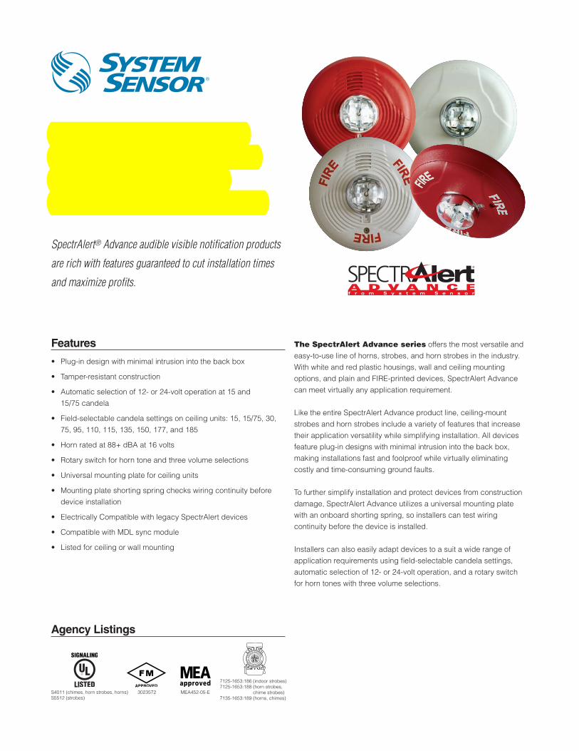
The SpectrAlert Advance series offers the most versatile and easy-to-use line of horns, strobes, and horn strobes in the industry. With white and red plastic housings, wall and ceiling mounting options, and plain and FIRE-printed devices, SpectrAlert Advance can meet virtually any application requirement.
Like the entire SpectrAlert Advance product line, ceiling-mount strobes and horn strobes include a variety of features that increase their application versatility while simplifying installation. All devices feature plug-in designs with minimal intrusion into the back box, making installations fast and foolproof while virtually eliminating costly and time-consuming ground faults.
To further simplify installation and protect devices from construction damage, SpectrAlert Advance utilizes a universal mounting plate with an onboard shorting spring, so installers can test wiring continuity before the device is installed.
Installers can also easily adapt devices to a suit a wide range of application requirements using field-selectable candela settings, automatic selection of 12- or 24-volt operation, and a rotary switch for horn tones with three volume selections.
Indoor Selectable-Output Strobes and Horn Strobes for Ceiling Applications
SpectrAlert® Advance audible visible notification products
are rich with features guaranteed to cut installation times
and maximize profits.
MEA452-05-E3023572
7125-1653:186 (indoor strobes)7125-1653:188 (horn strobes,
chime strobes)7135-1653:189 (horns, chimes)
S4011 (chimes, horn strobes, horns)S5512 (strobes)

AVDS00501
SpectrAlert Advance SpecificationsArchitect/Engineer SpecificationsGeneralSpectrAlert Advance strobes and horn strobes shall mount to a standard 4 × 4 × 1½-inch back box, 4-inch octagon back box, or double-gang back box. Two-wire products shall also mount to a single-gang 2 × 4 × 17⁄8-inch back box. A universal mounting plate shall be used for mounting ceiling and wall products. The notification appliance circuit wiring shall terminate at the universal mounting plate. Also, SpectrAlert Advance products, when used with the Sync•Circuit™ Module accessory, shall be powered from a non-coded notification appliance circuit output and shall operate on a nominal 12 or 24 volts. When used with the Sync•Circuit Module, 12-volt-rated notification appliance circuit outputs shall operate between 9 and 17.5 volts; 24-volt-rated notification appliance circuit outputs shall operate between 17 and 33 volts. Indoor SpectrAlert Advance products shall operate between 32 and 120 degrees Fahrenheit from a regulated DC or full-wave rectified unfiltered power supply. Strobes and horn strobes shall have field-selectable candela settings including 15, 15/75, 30, 75, 95, 110, 115, 135, 150, 177, and 185.
StrobeThe strobe shall be a System Sensor SpectrAlert Advance Model _______ listed to UL 1971 and shall be approved for fire protective service. The strobe shall be wired as a primary-signaling notification appliance and comply with the Americans with Disabilities Act requirements for visible signaling appliances, flashing at 1 Hz over the strobe’s entire operating voltage range. The strobe light shall consist of a xenon flash tube and associated lens/reflector system.
Horn Strobe CombinationThe horn strobe shall be a System Sensor SpectrAlert Advance Model _______ listed to UL 1971 and UL 464 and shall be approved for fire protective service. The horn strobe shall be wired as a primary-signaling notification appliance and comply with the Americans with Disabilities Act requirements for visible signaling appliances, flashing at 1 Hz over the strobe’s entire operating voltage range. The strobe light shall consist of a xenon flash tube and associated lens/reflector system. The horn shall have three audibility options and an option to switch between a temporal three pattern and a non-temporal (continuous) pattern. These options are set by a multiple position switch. On four-wire products, the strobe shall be powered independently of the sounder. The horn on horn strobe models shall operate on a coded or non-coded power supply.
Synchronization ModuleThe module shall be a System Sensor Sync•Circuit model MDL listed to UL 464 and shall be approved for fire protective service. The module shall synchronize SpectrAlert strobes at 1 Hz and horns at temporal three. Also, while operating the strobes, the module shall silence the horns on horn strobe models over a single pair of wires. The module shall mount to a 411⁄16 × 411⁄16 × 21⁄8-inch back box. The module shall also control two Style Y (class B) circuits or one Style Z (class A) circuit. The module shall synchronize multiple zones. Daisy chaining two or more synchronization modules together will synchronize all the zones they control. The module shall not operate on a coded power supply.
Physical/Electrical SpecificationsStandard Operating Temperature 32°F to 120°F (0°C to 49°C)Humidity Range 10 to 93% non-condensingStrobe Flash Rate 1 flash per secondNominal Voltage Regulated 12 DC/FWR or regulated 24 DC/FWR1
Operating Voltage Range2 8 to 17.5 V (12 V nominal) or 16 to 33 V (24 V nominal)Input Terminal Wire Gauge 12 to 18 AWGCeiling-Mount Dimensions (including lens) 6.8˝ diameter × 2.5˝ high (173 mm diameter × 64 mm high)Ceiling-Mount Back Box Skirt Dimensions (BBSC-2, BBSCW-2) 7.1˝ diameter × 2.2˝ high (180 mm diameter × 57 mm high)Ceiling-Mount Trim Ring Dimensions (sold as a 5 pack) (TRC-HS, TRCW-HS)
6.9˝ diameter × 0.35˝ high (175 mm diameter × 9 mm high)
Notes:1. Full Wave Rectified (FWR) voltage is a non-regulated, time-varying power source that is used on some power supply and panel outputs.2. P, S, PC, and SC products will operate at 12 V nominal only for 15 and 15/75 cd.
AVDS00501
Horn Strobe Output (dBA)
Switch Position Sound Pattern dB
8–17.5 Volts
16–33Volts
24-Volt NominalReverberant Anechoic
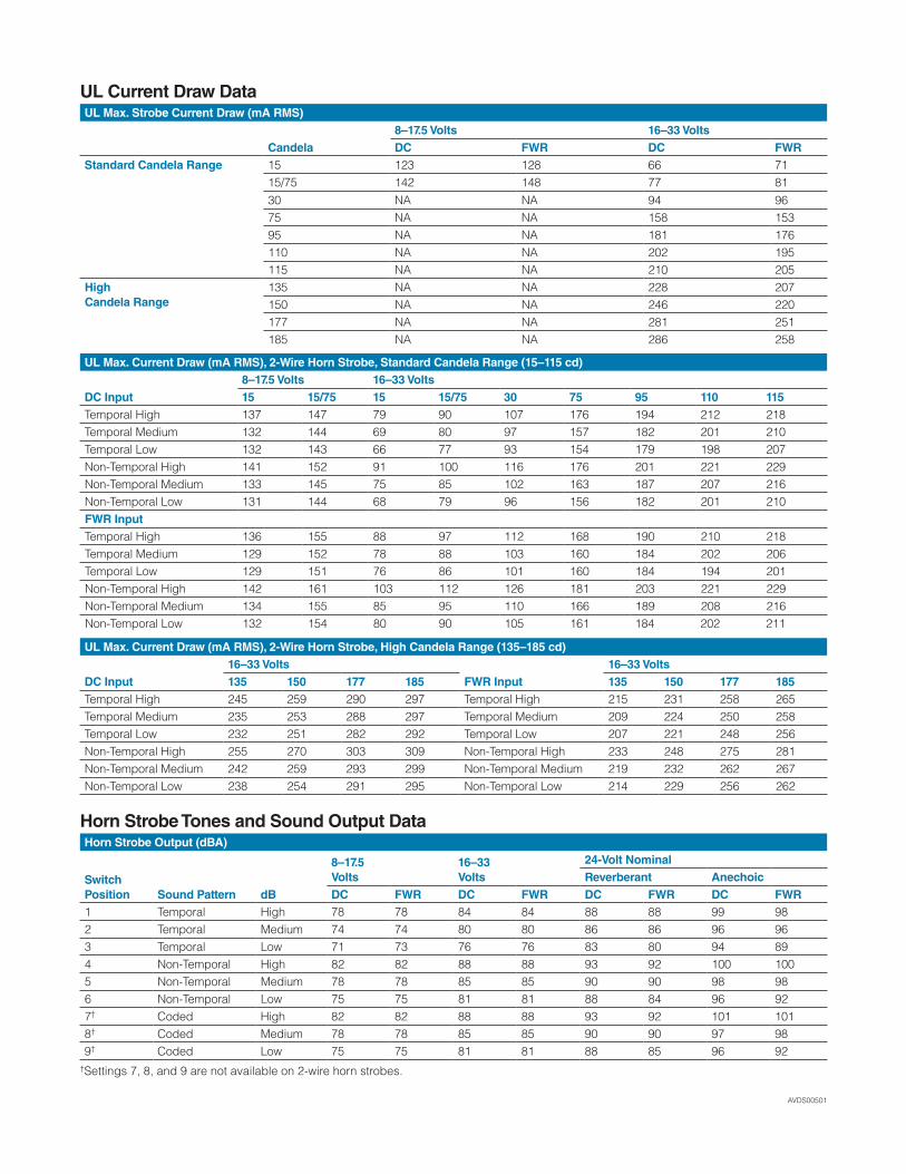
DC FWR DC FWR DC FWR DC FWR1 Temporal High 78 78 84 84 88 88 99 982 Temporal Medium 74 74 80 80 86 86 96 963 Temporal Low 71 73 76 76 83 80 94 894 Non-Temporal High 82 82 88 88 93 92 100 1005 Non-Temporal Medium 78 78 85 85 90 90 98 986 Non-Temporal Low 75 75 81 81 88 84 96 927† Coded High 82 82 88 88 93 92 101 1018† Coded Medium 78 78 85 85 90 90 97 989† Coded Low 75 75 81 81 88 85 96 92
†Settings 7, 8, and 9 are not available on 2-wire horn strobes.
UL Max. Strobe Current Draw (mA RMS)
Candela8–17.5 Volts 16–33 VoltsDC FWR DC FWR
Standard Candela Range 15 123 128 66 7115/75 142 148 77 8130 NA NA 94 9675 NA NA 158 15395 NA NA 181 176110 NA NA 202 195115 NA NA 210 205
HighCandela Range
135 NA NA 228 207150 NA NA 246 220177 NA NA 281 251185 NA NA 286 258
UL Max. Current Draw (mA RMS), 2-Wire Horn Strobe, Standard Candela Range (15–115 cd)
DC Input8–17.5 Volts 16–33 Volts15 15/75 15 15/75 30 75 95 110 115
Temporal High 137 147 79 90 107 176 194 212 218Temporal Medium 132 144 69 80 97 157 182 201 210Temporal Low 132 143 66 77 93 154 179 198 207Non-Temporal High 141 152 91 100 116 176 201 221 229Non-Temporal Medium 133 145 75 85 102 163 187 207 216Non-Temporal Low 131 144 68 79 96 156 182 201 210FWR InputTemporal High 136 155 88 97 112 168 190 210 218Temporal Medium 129 152 78 88 103 160 184 202 206Temporal Low 129 151 76 86 101 160 184 194 201Non-Temporal High 142 161 103 112 126 181 203 221 229Non-Temporal Medium 134 155 85 95 110 166 189 208 216Non-Temporal Low 132 154 80 90 105 161 184 202 211
UL Max. Current Draw (mA RMS), 2-Wire Horn Strobe, High Candela Range (135–185 cd)
DC Input16–33 Volts
FWR Input16–33 Volts
135 150 177 185 135 150 177 185Temporal High 245 259 290 297 Temporal High 215 231 258 265Temporal Medium 235 253 288 297 Temporal Medium 209 224 250 258Temporal Low 232 251 282 292 Temporal Low 207 221 248 256Non-Temporal High 255 270 303 309 Non-Temporal High 233 248 275 281Non-Temporal Medium 242 259 293 299 Non-Temporal Medium 219 232 262 267Non-Temporal Low 238 254 291 295 Non-Temporal Low 214 229 256 262
UL Current Draw Data
Horn Strobe Tones and Sound Output Data
3825 Ohio Avenue • St. Charles, IL 60174 Phone: 800-SENSOR2 • Fax: 630-377-6495
©2012 System Sensor.Product specifications subject to change without notice. Visit systemsensor.com
for current product information, including the latest version of this data sheet.AVDS00501 • 3/12
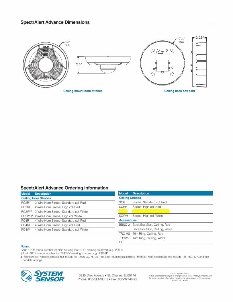
SpectrAlert Advance Dimensions
Model DescriptionCeiling Horn StrobesPC2R* 2-Wire Horn Strobe, Standard cd, RedPC2RH 2-Wire Horn Strobe, High cd, RedPC2W*† 2-Wire Horn Strobe, Standard cd, WhitePC2WH* 2-Wire Horn Strobe, High cd, WhitePC4R 4-Wire Horn Strobe, Standard cd, RedPC4RH 4-Wire Horn Strobe, High cd, RedPC4W 4-Wire Horn Strobe, Standard cd, White
SpectrAlert Advance Ordering Information
Notes:* Add “-P” to model number for plain housing (no “FIRE” marking on cover), e.g., P2R-P.† Add “-SP” to model number for “FUEGO” marking on cover, e.g., P2R-SP.‡ “Standard cd” refers to strobes that include 15, 15/75, 30, 75, 95, 110, and 115 candela settings. “High cd” refers to strobes that include 135, 150, 177, and 185
candela settings.
4.7˝
5.6˝
6.8˝Dia.
2.5˝
2.5˝ 2.23˝5.05˝
5.98˝
7.1˝Dia.
2.25˝
5.1˝
2.0˝
5.7˝
7.1˝Dia.
2.0˝
Ceiling-mount horn strobes Ceiling back box skirt
Model DescriptionCeiling StrobesSCR Strobe, Standard cd, RedSCRH Strobe, High cd, RedSCW* Strobe, Standard cd, WhiteSCWH Strobe, High cd, WhiteAccessoriesBBSC-2 Back Box Skirt, Ceiling, Red
Back Box Skirt, Ceiling, WhiteTRC-HS Trim Ring, Ceiling, RedTRCW-HS
Trim Ring, Ceiling, White

DN-6724:B3 • 2/17/2011 — Page 1 of 2
FCM-1(A) & FRM-1(A) SeriesControl and Relay Modules
Intelligent / Addressable Devices
DN-6724:B3
GeneralFCM-1(A) Control Module: The FCM-1(A) Addressable Con-trol Module provides Notifier intelligent fire alarm control pan-els a circuit for Notification Appliances (horns, strobes,speakers, etc.). Addressability allows the FCM-1(A) to be acti-vated, either manually or through panel programming, on aselect (zone or area of coverage) basis.
FRM-1(A) Relay Module: The FRM-1(A) Addressable RelayModule provides the system with a dry-contact output for acti-vating a variety of auxiliary devices, such as fans, dampers,control equipment, etc. Addressability allows the dry contact tobe activated, either manually or through panel programming,on a select basis.
FlashScan® (U.S. Patent 5,539,389) is a communication pro-tocol developed by NOTIFIER Engineering that greatlyenhances the speed of communication between analog intelli-gent devices. Intelligent devices communicate in a groupedfashion. If one of the devices within the group has new infor-mation, the panel CPU stops the group poll and concentrateson single points. The net effect is response speed greater thanfive times that of other designs.
Features• Built-in type identification automatically identifies these
devices to the control panel.
• Internal circuitry and relay powered directly by two-wireSLC loop. The FCM-1(A) module requires power (for horns,strobes, etc.), or audio (for speakers).
• Integral LED “blinks” green each time a communication isreceived from the control panel and turns on in steady redwhen activated.
• LED blink may be deselected globally (affects all devices).• High noise immunity (EMF/RFI).
• The FCM-1(A) may be used to switch 24-volt NAC power,audio (up to 70.7 Vrms).
• Wide viewing angle of LED.• SEMS screws with clamping plates for wiring ease.
• Direct-dial entry of address 01– 159 for FlashScan loops,01 – 99 for CLIP mode loops.
• Speaker, and audible/visual applications may be wired forClass B or A (Style Y or Z).
ApplicationsThe FCM-1(A) is used to switch 24 VDC audible/visual power,high-level audio (speakers). The FRM-1(A) may be pro-grammed to operate dry contacts for applications such as doorholders or Air Handling Unit shutdown, and to reset four-wiresmoke detector power.
NOTE: Refer to the SLC Manual (PN 51253) for details regardingreleasing applications with the FCM-1(A). Refer to the FCM-1-RELdatasheet (DN-60390) for new FlashScan® releasing applications.
Construction• The face plate is made of off-white heat-resistant plastic.• Controls include two rotary switches for direct-dial entry of
address (01-159).
• The FCM-1(A) is configured for a single Class B (Style Y) orClass A (Style Z) Notification Appliance Circuit.
• The FRM-1(A) provides two Form-C dry contacts thatswitch together.
OperationEach FCM-1(A) or FRM-1(A) uses one of 159 possible moduleaddresses on a SLC loop (99 on CLIP loops). It responds toregular polls from the control panel and reports its type andstatus, including the open/normal/short status of its Notifica-tion Appliance Circuit (NAC). The LED blinks with each pollreceived. On command, it activates its internal relay. TheFCM-1(A) supervises Class B (Style Y) or Class A (Style Z)notification or control circuits.
Upon code command from the panel, the FCM-1(A) will dis-connect the supervision and connect the external power sup-ply in the proper polarity across the load device. Thedisconnection of the supervision provides a positive indicationto the panel that the control relay actually turned ON. Theexternal power supply is always relay isolated from the com-munication loop so that a trouble condition on the externalpower supply will never interfere with the rest of the system.
Rotary switches set a unique address for each module. Theaddress may be set before or after mounting. The built-inTYPE CODE (not settable) will identify the module to the con-trol panel, so as to differentiate between a module and a sen-sor address.
Specifications for FCM-1(A)Normal operating voltage: 15 to 32 VDC.
Maximum current draw: 6.5 mA (LED on).
Average operating current: 350 μA direct poll, 375 μA grouppoll with LED flashing, 485 μA Max. (LED flashing, NACshorted.)
FCM-1(A)
7000
cov.
JPG

Page 2 of 2 — DN-6724:B3 • 2/17/2011
Notifier® and FlashScan® are registered trademarks of HoneywellInternational Inc. ©2011 by Honeywell International Inc. All rights reserved. Unauthorized useof this document is strictly prohibited.
This document is not intended to be used for installation purposes. We try to keep our product information up-to-date and accurate.
We cannot cover all specific applications or anticipate all requirements. All specifications are subject to change without notice.
For more information, contact Notifier. Phone: (203) 484-7161, FAX: (203) 484-7118.www.notifier.com
Made in the U.S. A.
Maximum NAC Line Loss: 4 VDC.
External supply voltage (between Terminals T10 and T11): Maximum (NAC): Regulated 24 VDC; Maximum(Speakers): 70.7 V RMS, 50W.
Drain on external supply: 1.7 mA maximum using 24 VDCsupply; 2.2 mA Maximum using 80 VRMS supply.
Max NAC Current Ratings: For class B wiring system, thecurrent rating is 3A; For class A wiring system, the current rat-ing is 2A.
Temperature range: 32°F to 120°F (0°C to 49°C).
Humidity range: 10% to 93% non-condensing.
Dimensions: 4.5" (114.3 mm) high x 4" (101.6 mm) wide x1.25" (31.75 mm) deep. Mounts to a 4" (101.6 mm) square x2.125" (53.975 mm) deep box.
Accessories: SMB500 Electrical Box; CB500 Barrier
Specifications for FRM-1(A)Normal operating voltage: 15 to 32 VDC.
Maximum current draw: 6.5 mA (LED on).
Average operating current: 230 μA direct poll; 255 μA grouppoll.
EOL resistance: not used.
Temperature range: 32°F to 120°F (0°C to 49°C).
Humidity range: 10% to 93% non-condensing.
Dimensions: 4.5" (114.3 mm) high x 4" (101.6 mm) wide x1.25" (31.75 mm) deep. Mounts to a 4" (101.6 mm) square x2.125" (53.975 mm) deep box.
Accessories: SMB500 Electrical Box; CB500 Barrier
Agency Listings and ApprovalsIn some cases, certain modules may not be listed by certainapproval agencies, or listing may be in process. Consult fac-tory for latest listing status.
• UL: S635• ULC: S3705 (A version only) • FM Approved• CSFM: 7300-0028:0219 • MEA: 14-00-E
• FDNY: COA #6067, #6065
Contact Ratings for FRM-1(A)
NOTE: Maximum (Speakers): 70.7 V RMS, 50 W
Product Line InformationNOTE: “A” suffix indicates ULC Listed model.
FCM-1(A): Intelligent Addressable Control Module.
FRM-1(A): Intelligent Addressable Relay Module.
A2143-20: Capacitor, required for Class A (Style Z) operationof speakers.
SMB500: Optional Surface-Mount Backbox.
CB500: Control Module Barrier — required by UL for separat-ing power-limited and non-power limited wiring in the samejunction box as FCM-1(A).
NOTE: For installation instructions, see the following documents:
• FCM-1(A) Installation document I56-1169.
• FRM-1(A) Installation document I56-3502.
• Notifier SLC Wiring Manual, document 51253.
Current Rating
Maximum Voltage
Load Description Application
3 A 30 VDC Resistive Non-Coded
2 A 30 VDC Resistive Coded
.9 A 110 VDC Resistive Non-Coded
.9 A 125 VDC Resistive Non-Coded
.5 A 30 VDCInductive(L/R=5ms)
Coded
1 A 30 VDCInductive(L/R=2ms)
Coded
.3 A 125 VACInductive(PF=0.35)
Non-Coded
1.5 A 25 VACInductive(PF=0.35) Non-Coded
.7 A 70.7 VACInductive(PF=0.35) Non-Coded
2 A 25 VACInductive(PF=0.35) Non-Coded

DN-6720:C • 10/06/2010 — Page 1 of 4
FMM-1(A), FMM-101(A),FZM-1(A) & FDM-1(A)Monitor Modules with FlashScan®
Intelligent/Addressable Devices
DN-6720:C • H-220
GeneralFour different monitor modules are available for Notifier’s intel-ligent control panels for a variety of applications. Monitor mod-ules supervise a circuit of dry-contact input devices, such asconventional heat detectors and pull stations, or monitor andpower a circuit of two-wire smoke detectors (FZM-1(A)).
FMM-1(A) is a standard-sized module (typically mounts to a 4"[10.16 cm] square box) that supervises either a Style D (ClassA) or Style B (Class B) circuit of dry-contact input devices.
FMM-101(A) is a miniature monitor module a mere 1.3" (3.302cm) H x 2.75" (6.985 cm) W x 0.5" (1.270 cm) D that super-vises a Style B (Class B) circuit of dry-contact input devices.Its compact design allows the FMM-101(A) to be mounted in asingle-gang box behind the device it monitors.
FZM-1(A) is a standard-sized module that monitors and super-vises compatible two-wire, 24 volt, smoke detectors on a StyleD (Class A) or Style B (Class B) circuit.
FDM-1(A) is a standard-sized dual monitor module that moni-tors and supervises two independent two-wire Style B (ClassB) dry-contact initiating device circuits (IDCs) at two separate,consecutive addresses in intelligent, two-wire systems.
FlashScan® (U.S. Patent 5,539,389) is a communication pro-tocol developed by NOTIFIER that greatly increases the speedof communication between analog intelligent devices. Intelli-gent devices communicate in a grouped fashion. If one of thedevices within the group has new information, the panel CPUstops the group poll and concentrates on single points. Thenet effect is response speed greater than five times that ofother designs.
FMM-1(A) Monitor Module• Built-in type identification automatically identifies this device
as a monitor module to the control panel.• Powered directly by two-wire SLC loop. No additional power
required.• High noise (EMF/RFI) immunity.
• SEMS screws with clamping plates for ease of wiring.• Direct-dial entry of address: 01 – 159 on FlashScan loops;
01 – 99 on CLIP loops. • LED flashes green during normal operation (this is a pro-
grammable option) and latches on steady red to indicatealarm.
The FMM-1(A) Monitor Module is intended for use in intelli-gent, two-wire systems, where the individual address of eachmodule is selected using the built-in rotary switches. It pro-vides either a two-wire or four-wire fault-tolerant InitiatingDevice Circuit (IDC) for normally-open-contact fire alarm andsupervisory devices. The module has a panel-controlled LEDindicator. The FMM-1(A) can be used to replace MMX-1(A)modules in existing systems.
FMM-1(A) APPLICATIONSUse to monitor a zone of four-wire smoke detectors, manualfire alarm pull stations, waterflow devices, or other normally-open dry-contact alarm activation devices. May also be usedto monitor normally-open supervisory devices with specialsupervisory indication at the control panel. Monitored circuitmay be wired as an NFPA Style B (Class B) or Style D (Class
A) Initiating Device Circuit. A 47K ohm End-of-Line Resistor(provided) terminates the Style B circuit. No resistor isrequired for supervision of the Style D circuit.
FMM-1(A) OPERATIONEach FMM-1(A) uses one of the available module addresseson an SLC loop. It responds to regular polls from the controlpanel and reports its type and the status (open/normal/short)of its Initiating Device Circuit (IDC). A flashing LED indicatesthat the module is in communication with the control panel.The LED latches steady on alarm (subject to current limita-tions on the loop).
FMM-1(A) SPECIFICATIONSNominal operating voltage: 15 to 32 VDC.
Maximum current draw: 5.0 mA (LED on).
Average operating current: 350 μA (LED flashing), 1 com-munication every 5 seconds, 47k EOL.
Maximum IDC wiring resistance: 40 ohms.
EOL resistance: 47K ohms.
Temperature range: 32°F to 120°F (0°C to 49°C).
Humidity range: 10% to 93% noncondensing.
Dimensions: 4.5" (11.43 cm) high x 4" (10.16 cm) wide x1.25" (3.175 cm) deep. Mounts to a 4" (10.16 cm) square x2.125" (5.398 cm) deep box.
FMM-1(A) (Type H)
6999
cov.
jpg

Page 2 of 4 — DN-6720:C • 10/06/2010
FMM-101(A) Mini Monitor Module• Built-in type identification automatically identifies this device
as a monitor module to the panel.• Powered directly by two-wire SLC loop. No additional power
required.• High noise (EMF/RFI) immunity.• Tinned, stripped leads for ease of wiring.
• Direct-dial entry of address: 01 – 159 on FlashScan loops;01 – 99 on CLIP loops.
The FMM-101(A) Mini Monitor Module can be installed in asingle-gang junction directly behind the monitored unit. Itssmall size and light weight allow it to be installed without rigidmounting. The FMM-101(A) is intended for use in intelligent,two-wire systems where the individual address of each moduleis selected using rotary switches. It provides a two-wire initiat-ing device circuit for normally-open-contact fire alarm andsecurity devices. The FMM-101(A) can be used to replaceMMX-101(A) modules in existing systems.
FMM-101(A) APPLICATIONSUse to monitor a single device or a zone of four-wire smokedetectors, manual fire alarm pull stations, waterflow devices, orother normally-open dry-contact devices. May also be used tomonitor normally-open supervisory devices with special super-visory indication at the control panel. Monitored circuit/deviceis wired as an NFPA Style B (Class B) Initiating Device Circuit.A 47K ohm End-of-Line Resistor (provided) terminates the cir-cuit.
FMM-101(A) OPERATIONEach FMM-101(A) uses one of the available moduleaddresses on an SLC loop. It responds to regular polls fromthe control panel and reports its type and the status (open/nor-mal/short) of its Initiating Device Circuit (IDC).
FMM-101(A) SPECIFICATIONSNominal operating voltage: 15 to 32 VDC.
Average operating current: 350 μA, 1 communication every5 seconds, 47k EOL; 600 μA Max. (Communicating, IDCShorted).
Maximum IDC wiring resistance: 40 ohms.
Maximum IDC Voltage: 11 Volts.
Maximum IDC Current: 400 μA.
EOL resistance: 47K ohms.
Temperature range: 32°F to 120°F (0°C to 49°C).
Humidity range: 10% to 93% noncondensing.
Dimensions: 1.3" (3.302 cm) high x 2.75" (6.985 cm) wide x0.65" (1.651 cm) deep.
Wire length: 6" (15.24 cm) minimum.
FZM-1(A) Interface Module• Supports compatible two-wire smoke detectors.• Supervises IDC wiring and connection of external power
source.• High noise (EMF/RFI) immunity.
• SEMS screws with clamping plates for ease of wiring.• Direct-dial entry of address: 01 – 159 on FlashScan loops,
01 – 99 on CLIP loops.• LED flashes during normal operation; this is a programma-
ble option.• LED latches steady to indicate alarm on command from
control panel.The FZM-1(A) Interface Module is intended for use in intelli-gent, addressable systems, where the individual address ofeach module is selected using built-in rotary switches. Thismodule allows intelligent panels to interface and monitor two-wire conventional smoke detectors. It transmits the status (nor-mal, open, or alarm) of one full zone of conventional detectorsback to the control panel. All two-wire detectors being moni-tored must be UL compatible with the module. The FZM-1(A)can be used to replace MMX-2(A) modules in existing sys-tems.
FZM-1(A) APPLICATIONSUse the FZM-1(A) to monitor a zone of two-wire smoke detec-tors. The monitored circuit may be wired as an NFPA Style B(Class B) or Style D (Class A) Initiating Device Circuit. A 3.9 Kohm End-of-Line Resistor (provided) terminates the end of theStyle B or D (class B or A) circuit (maximum IDC loop resis-tance is 25 ohms). Install ELR across terminals 8 and 9 forStyle D application.
FZM-1(A) OPERATIONEach FZM-1(A) uses one of the available module addresseson an SLC loop. It responds to regular polls from the controlpanel and reports its type and the status (open/normal/short)of its Initiating Device Circuit (IDC). A flashing LED indicatesthat the module is in communication with the control panel.The LED latches steady on alarm (subject to current limita-tions on the loop).
FZM-1(A) SPECIFICATIONSNominal operating voltage: 15 to 32 VDC.
Maximum current draw: 5.1 mA (LED on).
Maximum IDC wiring resistance: 25 ohms.
Average operating current: 300 μA, 1 communication and 1LED flash every 5 seconds, 3.9k eol.
EOL resistance: 3.9K ohms.
External supply voltage (between Terminals T3 and T4):DC voltage: 24 volts power limited. Ripple voltage: 0.1 Vrmsmaximum. Current: 90 mA per module maximum.
Temperature range: 32°F to 120°F (0°C to 49°C).
Humidity range: 10% to 93% noncondensing.
Dimensions: 4.5" (11.43 cm) high x 4" (10.16 cm) wide x1.25" (3.175 cm) deep. Mounts to a 4" (10.16 cm) square x2.125" (5.398 cm) deep box.
6720m101.w
mf

DN-6720:C • 10/06/2010 — Page 3 of 4
FDM1(A) Dual Monitor ModuleThe FDM-1(A) Dual Monitor Module is intended for use in intelli-gent, two-wire systems. It provides two independent two-wireinitiating device circuits (IDCs) at two separate, consecutiveaddresses. It is capable of monitoring normally open contact firealarm and supervisory devices; or either normally open or nor-mally closed security devices. The module has a single panel-controlled LED.
NOTE: The FDM-1(A) provides two Style B (Class B) IDC circuitsONLY. Style D (Class A) IDC circuits are NOT supported in anyapplication.
FDM-1(A) SPECIFICATIONSNormal operating voltage range: 15 to 32 VDC.
Maximum current draw: 6.4 mA (LED on).
Average operating current: 750 μA (LED flashing).
Maximum IDC wiring resistance: 1,500 ohms.
Maximum IDC Voltage: 11 Volts.
Maximum IDC Current: 240 μA
EOL resistance: 47K ohms.
Maximum SLC Wiring resistance: 40 Ohms.
Temperature range: 32° to 120°F (0° to 49°C).
Humidity range: 10% to 93% (non-condensing).
Dimensions: 4.5" (11.43 cm) high x 4" (10.16 cm) wide x2.125" (5.398 cm) deep.
FDM-1(A) AUTOMATIC ADDRESSINGThe FDM-1(A) automatically assigns itself to two addressablepoints, starting with the original address. For example, if theFDM-1(A) is set to address “26”, then it will automaticallyassign itself to addresses “26” and “27”.
NOTE: “Ones” addresses on the FDM-1(A) are 0, 2, 4, 6, or 8 only.Terminals 6 and 7 use the first address, and terminals 8 and 9 usethe second address.
InstallationFMM-1(A), FZM-1(A), and FDM-1(A) modules mount directlyto a standard 4" (10.16 cm) square, 2.125" (5.398 cm) deep,electrical box. They may also be mounted to the SMB500 sur-face-mount box. Mounting hardware and installation instruc-tions are provided with each module. All wiring must conformto applicable local codes, ordinances, and regulations. Thesemodules are intended for power-limited wiring only.
The FMM-101(A) module is intended to be wired and mountedwithout rigid connections inside a standard electrical box. Allwiring must conform to applicable local codes, ordinances, andregulations.
Agency Listings and ApprovalsIn some cases, certain modules may not be listed by certainapproval agencies, or listing may be in process. Consult fac-tory for latest listing status.
• UL: S635• ULC: S635 • FM Approved • CSFM: 7300-0028:0219• MEA: 457-99-E• U.S. Coast Guard:
– 161.002/23/3 (AFP-200: FMM-1/-101, FZM-1)
– 161.002/42/1 (NFS-640: FMM-1/-101)• Lloyd’s Register:
– 03/60011/E1 (FMM-1/-101, FZM-1)
– 94/60004/E2 (AFP-200: except FDM-1) – 02/60007 (NFS-640: FDM-1)
• FDNY: COA #6038 (NFS2-640, NFS-320), COA# 6058(NFS2-3030)
Product Line InformationNOTE: “A” suffix indicates ULC-listed model.
FMM-1(A): Monitor module.
FMM-101(A): Monitor module, miniature.
FZM-1(A): Monitor module, two-wire detectors.
FDM-1(A): Monitor module, dual, two independent Class B cir-cuits.
SMB500: Optional surface-mount backbox.
NOTE: See installation instructions and refer to the SLC WiringManual, PN 51253.
! CAUTION: Avoid duplicating addresses on the system.

Page 4 of 4 — DN-6720:C • 10/06/2010
FlashScan® and NOTIFIER® are registered trademarks and FireWatch™ isa trademark of Honeywell International Inc.©2010 by Honeywell International Inc. All rights reserved. Unauthorized useof this document is strictly prohibited.
This document is not intended to be used for installation purposes. We try to keep our product information up-to-date and accurate.
We cannot cover all specific applications or anticipate all requirements. All specifications are subject to change without notice.
For more information, contact Notifier. Phone: (203) 484-7161, FAX: (203) 484-7118.www.notifier.com
Made in the U.S. A.