subsea pipeline design for natural gas transportation: a case … · 2020-01-30 · subsea pipeline...
TRANSCRIPT

International Journal of Petroleum and Petrochemical Engineering (IJPPE)
Volume 4, Issue 3, 2018, PP 21-34
ISSN 2454-7980 (Online)
DOI: http://dx.doi.org/10.20431/2454-7980.0403003
www.arcjournals.org
International Journal of Petroleum and Petrochemical Engineering (IJPPE) Page | 21
Subsea Pipeline Design for Natural Gas Transportation: A Case
Study of Côte D’ivoire’s Gazelle Field
S. A. Marfo1*, P. Opoku Appau2, L. A. A. Kpami1
1Department of Petroleum Engineering, University of Mines and Technology, Tarkwa, Ghana .
2Research Institute of Enhanced Oil Recovery, China University of Petroleum (Beijing), P. R. China .
1. INTRODUCTION
Natural gas which is commercially extracted from oil fields and natural gas fields has emerged as a cheaper and efficient source of energy. It has become a fuel of choice for various uses. It is used
extensively by domestic consumers for cooking and heating, by power producers for generating
electricity and by petrochemical and fertilizer industries as both fuel and feedstock [1, 2]. A major challenge associated with the extraction and use of the natural gas is the problem of transporting.
Therefore there is the need to effectively transport gas from the gas fields to the processing units and
from the processing unit to the end users. Over the years, pipelines have shown to be the safest, most
efficient and economical mode of transporting natural gas [3]. Pipelines are lifeline of the global oil and gas industry, providing economic, reliable means to transport oil and natural gas from upstream
production to downstream refineries, power stations and market [4]. Generally defined as a long line
of connected segment of pipe, with pumps, valves and other equipment needed for operating the system, pipelines have been used for transportation of liquids and gases for thousands of years [5].
Piping systems are like arteries and veins; they carry the lifeblood of modern civilisation [6]. In
developed nations, gas pipelines have extensively been constructed to supply gas from oil fields to
processing units and from these processing units to factories and homes where they are consumed. Pipelines are vitally important to the economic wellbeing and security of most nations [7].
Produced natural gas stream from the reservoir is always saturated with water and one of the problems
associated with its transmission especially in subsea pipeline is the formation of hydrate which is
defined as crystalline structures between water and hydrocarbon [8]. The design of subsea pipeline
known as pipeline that is laid on the seabed or below it inside a trench need to take into account a large number of factors [9]. Hydrate formation in subsea pipeline is a major problem that arises due to
temperature drop and other thermodynamic changes during production [10, 11]. The pipeline is
exposed to the cooling sea current, thus the gas inside the pipeline is cooled down to temperatures that
Abstract: Pipeline plays a vital role in modern civilisation as it provides the needed fuels for sustaining
imperative functions such as power generation, heating supply, and transportation. The cost of installing
underwater pipelines is a significant factor in the economics of offshore natural gas exploitation. Pr oper
design of these networks can facilitate the economic integration of newly discovered fields into the gathering
system and result in lower prices to the consumer. This study employs PIPESIM software to design a subsea
pipeline for transportation of natural gas from Gazelle Field in Côte d’Ivoire to a processing platform
located 30 km and to predict the conditions under which hydrate will form so as to be avoided. The design
comprised of two risers and one flowline. Hydrate was anticipated to form at a temperature of 65 °F for an
arrival pressure of 800 psia. For optimal insulation thickness to be achieved in the design, different
insulation materials and thicknesses were simulated. The insulation thickness for the flowline was determined
to be 0.75 in. with specific pipe size of 10 in. to satisfy the arrival pressure condition. The gas composition
and flow line thermal insulation are of prime importance within a design process to guarantee that pipeline
operate normally.
Keywords: Flow Assurance, Flowline, Hydrate, Natural Gas, Phase Envelope, PIPESIM
*Corresponding Author: S. A. Marfo, Department of Petroleum Engineering, University of Mines and
Technology, Tarkwa, Ghana.

Subsea Pipeline Design for Natural Gas Transportation: A Case Study of Côte D’ivoire’s Gazelle Field
International Journal of Petroleum and Petrochemical Engineering (IJPPE) Page | 22
favours hydrate formation. Therefore preventing hydrate formation in subsea pipelines to assure the
smooth operation of pipeline is of paramount importance [12].
Insulating subsea pipeline is essential to avoid hydrate formation [13]. Insulation provide hydrate control by maintaining temperature above the hydrate condition, it also extends the cool down time before reaching hydrate formation temperature [14, 15]. Oil and gas pipelines are insulated mainly to conserve energy by reducing heat loss and to facilitate the temperature control process [16]. The need to keep the fluids in the pipeline at a temperature higher than the ambient temperature could exist for reasons which include flow assurance [17]. The problem of design procedure is to find a pipeline configuration and size within the constraints which is safe and economical [18]. This paper therefore aims at developing a subsea pipeline that deals with problems that arises during transportation of natural gas from a production field to a processing platform, using Gazelle Field in Côte d’Ivoire as a case study.
1.1. Background Study
The Gazelle oil and gas field is located in Block CI-202, covering an area of 707 km2 located just 30 km to the southeast of Abidjan, the primary commercial centre of Côte d’Ivoire, extending from the coastline to water depths ranging between 30 m and 50 m in the offshore Ivorian Basin. The Gazelle Field was discovered in 1977 by Esso and tested a mixture of gas and oil over a number of tests. A total of seven appraisal wells were drilled in 1977-2012 with Esso drilling three. The Gazelle oil and gas Field is expected to hold 92 Bcf of gas. The block lies in water depths ranging from 0 to 1000 m, with most of the block situated in water depths of less than 100 m. The block is a highly prospective exploration license with 6 oil and gas discoveries. It has a significant database of block-wide high quality 3D seismic, 15 wells and over 20 production tests, some of which have produced gas at up to 48 MMscfd and oil at over 5000 bopd [19].
Figure1. Ivorian Basin showing Gazelle Oil and Gas Field (Anon, 2013)
The Gazelle oil and gas field is owned and operated by Vioco Petroleum Limited (formerly Railto Energy), which holds an 87 % working interest, while the remaining 13 % share in the field is held by state-owned oil company Petroci (Société Nationale d’Opérations Pétrolières de la Côte d’Ivoire). The field development plan and gas agreement consisted of a fixed production platform at the Gazelle Field with separate oil and gas pipelines from the platform to shore. The oil and gas production will be processed and exported via bundled pipelines to existing onshore infrastructure, located 19 miles (30 km) to the northwest of CI-202. The platform will have a production capacity of up to 40,000 bopd and 230 MMcf/d to allow for further infill drilling at Gazelle and the tie-back of existing satellite fields [20, 21].
The overall Gazelle field development concept is based on transporting Gazelle gas to an onshore gas plant located at the east of Grand Bassam for processing, from where it will be transferred to an Independent Power Plant (IPP) which will be contracted by CI-Energies to produce electricity for the National Grid. The Gazelle well stream will be directly transferred to shore through a multiphase pipeline to the onshore processing plant located to the East of Grand Bassam. After treatment, the Gazelle gas feeds a power plant located a short distance from the Vioco plant [22].
1.2. Flow Assurance
Flow assurance deals with the process of ensuring the safe transport of reservoir fluids right from the production point to the users’ end in an economical manner [23]. In subsea transportation of natural gas, flow assurance is considered crucial because of anticipated high pressure and low temperature

Subsea Pipeline Design for Natural Gas Transportation: A Case Study of Côte D’ivoire’s Gazelle Field
International Journal of Petroleum and Petrochemical Engineering (IJPPE) Page | 23
[10]. This process therefore requires a comprehensive knowledge about multiphase flow of fluids and the factors that can have an impact on these fluids. As fluids flow from one point to the other, there are also the risk of reduction in the fluid parameter, in other sense flow assurance which can result in the deposition of hydrates, wax, asphaltene and scale in the flowline. Due to the nature of the subsea environment, it is imperative to quantify the potential and extent of the problems that arises during the flow of fluid in order to mitigate the problems [24]. Although there are various problems that limit the efficiency of flow assurance, however, this paper focuses on hydrate formation and its implication on the fluid being transported.
1.2.1. Hydrate Formation in Pipeline
The oil industry today is forced into less accessible areas to acquire more oil to satisfy the growing energy market. The subsea environment which involves low temperatures as well as high pressures, high water cuts, and longer transfer times provide conditions that are ideal for hydrates and wax formation, and other solids deposits. These are the fundamental impediments to production of oil and gas through long distance subsea pipelines [25]. In deepwater oil exploration wells located far from platforms, crude oil often has to be transported over long distances in subsea pipelines [26]. The oil is cooled on its way to the destination due to heat transfer through the pipelines walls with the surrounding sea water. Temperature related transportation problems can take place if the pipelines are not insulated leading to rapid temperature drop. This may lead to the precipitation of asphaltenes and/or paraffin wax and the formation of hydrates [27]. Gas hydrates form in pipelines and production facilities at elevated pressures and reduced temperatures resulting to blocked pipeline, high removal cost and environmental risks. Offshore production of oil and gas operations are exposed to certain pressure and temperature conditions which can lead to gas hydrate formation and severe flow assurance problems in pipelines and other facilities. Gas hydrate formation is undesirable in oil and gas pipelines making their prevention necessary when they are formed [28].
1.2.2. Hydrate Mitigation and Remediation
For stable hydrate crystals to form in oil and gas production systems, four essential elements must be present; supply of hydrate forming guest molecules such as N2, CO2, H2S, CH4, C2H8, and other hydrocarbon molecules; water; low temperature and high pressure [29]. Strategies for hydrate mitigation and remediation often modify one or more of these elements to destabilise the hydrate and thus remove the problem. The various methods of hydrate control presented by several researchers [30-34] include controlling pressure outside hydrate envelope; temperature control by passive or active insulation (such as Direct Electrical Heating - DEH); removing supply of water by dehydration or separation; removal of supply of hydrate formers by gas-liquid separation; and injection of chemical inhibitors such as methanol and ethanol among others.
1.3. Pipeline Design Consideration
1.3.1. Factors Influencing Pipeline Design
Many factors must be considered in the design of long distance gas pipeline. These include the nature
of the gas to be transmitted, the length of the line, the type of terrain to be crossed, and maximum elevation of route [35]. When natural gas is produced from wells, it is treated, then transported via
transmission pipeline to distribution network systems, and to the consumers [36]. Gas pipelines
require special attention over and above the normal design requirements for liquids because of the vast quantity of stored energy in the pipeline steel due to the compressibility of gas. Therefore, in
order to achieve the optimum operation and management for a pipeline system, complex engineering
and technological studies must be conducted to determine pipeline steel material and size selection, pressure and temperature requirement, flow velocity, coating and cathodic protection design [37].
1.3.2. Offshore Pipelines
Offshore pipeline design differs primarily in the requirements of the environment and the installation
process. Pipe used in offshore applications is subjected to high bending stresses potential crushing forces, especially for pipes installed in deep water and a low-density environment. Until recently, the
pipeline size was severely limited, but technological developments and improved construction
methods have enabled offshore pipelines to continue to increase in size and capacity. Pipelines up to
28-in. diameter are now installed in the deep-water applications up to 7,000 ft of water [38].

Subsea Pipeline Design for Natural Gas Transportation: A Case Study of Côte D’ivoire’s Gazelle Field
International Journal of Petroleum and Petrochemical Engineering (IJPPE) Page | 24
1.3.3. Parameters Required in Pipeline Design
For gas flow in pipes, three simplified derivative equations can be employed to calculate the flow namely, Weymouth, Panhandle and the Spitzglass equations. All three equations are effective, however, the accuracy and applicability of each falls within certain ranges of flow and pipe diameter. The Weymouth equation is recommended for smaller-diameter pipe (generally, 12 in. and less), shorter lengths of segments (< 20 miles) within production batteries and for branch gathering lines, medium- to high-pressure (+/–100 psig to > 1,000 psig) applications, and a high Reynolds number. Panhandle equation on the other hand is recommended for 12-in. pipe diameter and greater. It is also recommended for long runs of pipe (> 20 miles) such as cross-country transmission pipelines and for moderate Reynolds numbers. The Spitzglass equation is recommended for low-pressure vent lines < 12 in. in diameter (ΔP < 10% of P1) [39]. In this paper, all three equations were used at a specific periods throughout the flow of fluid in the pipeline.
Weymouth equation
2
1
1
2
2
2
167.21.1
LSZT
PPdQg
[1]
Panhandle equation
51.2
51.0
961.0
2
2
2
1028.0 dZTLS
PPEQg
m
[2] Spitzglass equation
2
1
5
03.06.3
1
09.0
dd
SL
hwdQg
[3]
Reynolds number and Moody friction factor
The Reynolds number is a dimensionless parameter that is useful in characterising the degree of turbulence in the flow regime and is needed to determine the Moody friction factor. The Moody friction factor f is a function of the Reynolds number and the roughness of the internal surface of the pipe and is given by Friction-factor chart. The Moody friction factor is dependent on the characteristic of the flow in the pipe. For laminar flow, where Re is < 2,000, there is little mixing of the flowing fluid, and the flow velocity is parabolic; the Moody friction factor is expressed as f = 64/Re. For turbulent flow, where Re > 4,000, the flow mixes completely producing uniform velocity profile; and f depends on Re and the relative roughness (Ɛ/D) (ratio of absolute roughness, Ɛ to the pipe internal diameter, D) [39].
The general equation for Reynolds numbers is expressed as:
vdRe [4]
The Reynolds number for liquids can be expressed as:
d
lQSG1.92Re [5]
The Reynolds number for gases can be expressed as:
d
SQg.100,20Re
[6] Pressure drop for liquid flow
P
fLQd l
)105.11( 65
[7]

Subsea Pipeline Design for Natural Gas Transportation: A Case Study of Côte D’ivoire’s Gazelle Field
International Journal of Petroleum and Petrochemical Engineering (IJPPE) Page | 25
Pressure drop for gas flow
The general equation for calculating gas flow is stated as:
1
2
2
2
1
2
11
22
log2
144
P
PP
P
P
d
fLV
gAW
e
[8]
For practical pipeline purposes, equation 8 can be simplified to:
5
2
2
2
1 5.25d
SQgZTfLPP
[9]
The above equation assumes no work done; steady-state flow and ƒ=constant and is as a function of
the length. Also, since equation 8 was simplified certain assumptions were made in the application of
each of the three equations (7, 8 and 9). The equations used in this paper were obtained from already
established pressure drop gas flow equations [39].
1.4. Pipeline Insulation
Generally, insulations are defined as those materials or combinations of materials which retard the
flow of heat energy by conserving energy by reducing heat loss or gain; facilitate temperature control
of process and prevent vapour flow and water condensation on cold surfaces [40]. Insulating pipes
and subsea structures is essential to avoid the possibility of wax and hydrate formation. The most
commonly used materials in subsea thermal insulation are polyurethanes and polypropylenes, due to
their suitability for large scale production, availability of raw materials and system cost [41]. Oil and
gas field pipelines are insulated mainly to conserve heat. The need to keep the product fluids in the
pipeline at a temperature higher than the ambient temperature could exist, for reasons which include
flow assurance [17]. Thermal insulation is necessary to avoid formation of hydrate plugs and wax
build-up in subsea structures. Without thermal insulation cold seawater rapidly cools down the fluid,
forming hydrate/wax blockages making it impossible for a safe flow. Thermal insulation materials are
applied in order to prevent formation of these blockages during a shutdown scenario or during normal
operations [42].
There are some specific requirements to be fulfilled for selecting a suitable insulation material and
these include; low thermal conductivity, high heat capacity, high density, ability to withstand high
hydrostatic pressure, economical, easy to install and maintain [43]. According to Sadafule et al.
(2014), there are several types of insulation materials available for Pipe-in-Pipe (PiP) design which
includes Polypropylene (PP), Polypropylene-Foam (PPF), Polypropyene-Reinforced Foam
Combination (RPPF), Polyurethane (PU), Polyurethane-Syntactic (SPU), and Polyurethane-Foam
(PUF). They are suggested to install multi-layer passive thermal insulation in order to maintain
pipeline temperature much longer [27].
2. RESOURCES AND METHODS USED
This study required collection of data on operating conditions. Secondary data on gas composition,
properties and gas entry pressure were collected from Vioco Petroleum Limited, Côte d’Ivoire. The
PIPESIM software was the facilities package for design, simulation and optimisation. This section
gives details of the procedure used in developing the application and the application functional test
carried.
2.1. The Main application form
The main application form is a multi-document form. Multi-document form are windows applications
that can hold more than one window. The interfaces are designed as parents and children, that is to
say some interfaces depend on others. Hence the main form is the parent form which holds all other
forms. Figure 2 shows the main application form. This form also holds the menu bar and the toolbar.
Subsea Pipeline Design for Natural Gas Transportation: A Case Study of Côte D’ivoire’s Gazelle Field
International Journal of Petroleum and Petrochemical Engineering (IJPPE) Page | 26
Figure2. Main Application Form
2.2. The Child Form
Child forms are the windows or a form launched within the main form and is dependent on the main form. These are some of the child form available in the software:
2.2.1. Project Creation
This form allows users to set project name, work order or purpose on creating a new project. Figure 3 shows the projects creation form.
Figure3. Project Creation Form
2.2.2. Data Input Form
This form allows users to make selections and input data value for generating the different phase envelop for designing pipeline. Figure 4 shows the data input dialog. The < the set up/compositional > menu was used to enter the pure hydrocarbon components given for this study. All the pure hydrocarbon components were selected from the component database. Finally the < add> button was used to include all the pure hydrocarbon been selected.
Figure4. Data Input Form

Subsea Pipeline Design for Natural Gas Transportation: A Case Study of Côte D’ivoire’s Gazelle Field
International Journal of Petroleum and Petrochemical Engineering (IJPPE) Page | 27
After the number of moles of pure components was added, the petroleum fraction tab was selected to characterise the petroleum fraction C7+ by entering the boiling point, the molecular weight and the specific gravity in row 1. The same procedure was repeated in order to enter the number of moles for C+ under the component selection tab. Also the hydrocarbon phase envelope was generated by selecting the phase envelop button, and its subsequent plot was obtained. Figure 5 show a hydrocarbon phase envelope plot.
Figure5. Sample of Plot of Hydrocarbon Phase Envelope
2.2.3. Hydrate Phase Envelope Identification Process
It is necessary to add the aqueous component pure water. The < setup/compositional > menu was used to select water by pressing the add button of which its respective concentration value was then added. With the help of the phase envelop button, an aqueous phase envelope and hydrate formation line was generated. Figure 6 shows a sample of plot identifying the hydrate envelope.
Figure6. Sample of Hydrate Phase Envelope
2.2.4. Pipeline Size Selection
The smallest pipeline ID that will allow the design flow rate of the gas to be transported from the satellite platform whilst maintaining an arrival pressure of not lower than that of the processing platform pressure is always the best. The tool bar allows the user to select all the necessary items as source, boundary nodes, risers and flowline for the completion of the model. Figure 7 show the tool bar.
Figure7. Tool bar
2.2.5. Design Form
This form displays the data and solution as one part also the pictograph of the designed prototype attached to a final report. An example of a completion model is shown in Figure 8.

Subsea Pipeline Design for Natural Gas Transportation: A Case Study of Côte D’ivoire’s Gazelle Field
International Journal of Petroleum and Petrochemical Engineering (IJPPE) Page | 28
Figure8. Completed Model Sample
3. RESULTS AND DISCUSSION
An application software for designing subsea pipeline to transport gas from a satellite platform to a processing platform was developed that yielded a compositional analysis of the gas to be transported. However, the secondary data used for this study were obtained from Vioco Petroleum Limited, Côte d’Ivoire. Tables 1 to 8 present all the data used in this study.
Table1. Boundary Conditions
Fluid inlet pressure at satellite platform 1,200 psia
Fluid inlet temperature at satellite platform 176 °F
Design liquid flowrate 50 MMscf
Maximum turndown 28 MMscf
Minimum arrival pressure at processing platform 800 psia
Minimum arrival temperature at processing platform 73 °F.
Table2. Pure Hydrocarbon Components
Component Moles
Methane 92.2300
Nitrogen 2.1411
Carbon (IV) oxide 0.5483
Ethane 2.8319
Propane 1.1232
i-Butane 0.2855
n-Butane 0.2984
i-Pentane 0.1319
n-Pentane 0.0938
n-Hexane 0.3159
Table3. Petroleum Fraction
Name Boiling Point(°F) Molecular Weight Specific Gravity Moles
C7+
Table4. Aqueous Component
Component Volume ratio (%bbl/bbl)
Water 10
Table5. Pipeline Sizes Available
I.D.(") Wall thickness (") Roughness (")
10 0.5 0.001
12 0.5 0.001
14 0.5 0.001
Table6. Pipeline Data
Height of undulations 10/1000
Horizontal distance 19 miles
Elevation difference 0
Wall thickness 0.5"
Roughness 0.001"
Ambient temperature 50 °F
Overall heat transfer coefficient 0.2 Btu/hr/ft2/°F

Subsea Pipeline Design for Natural Gas Transportation: A Case Study of Côte D’ivoire’s Gazelle Field
International Journal of Petroleum and Petrochemical Engineering (IJPPE) Page | 29
Table7. Pipeline Insulation Study Data
Pipe thermal conductivity 50 Btu/hr/ft/°F
Insulation thermal conductivity 0.15 Btu/hr/ft/°F
Insulation thickness available 0.75" or 1.0"
Ambient fluid Water
Ambient fluid velocity 1.64 ft/sec
Burial depth 0 (half buried)
Ground conductivity 1.5 Btu/hr/ft/°F
Table8. Data for Risers 1 and 2
Horizontal distance 0
Elevation difference (Riser 1) -30 m
Elevation difference (Riser 2) +30 m
Inner diameter 10"
Wall thickness 0.5"
Roughness 0.001"
Ambient temperature 50 °F
Overall heat transfer coefficient 0.2 Btu/hr/ft2/°F
3.1. Compositional Model of the Hydrocarbon Phase
A compositional fluid model allows the fluid physical properties to be estimated over the range of pressures and temperatures encountered by the fluid. The fluid model is made up of individual pure components such as methane, and petroleum fractions. Petroleum fractions are used to estimate the behaviour of groups of heavier pure components. The corresponding hydrocarbon phase envelope generated is shown in Figure 9.
Figure9. Hydrocarbon Phase Envelope Plot
3.2. Identification of the Hydrate Envelope
Certain fluid composition shows the tendency to form hydrate compounds in the presence of water. These compounds can cause line blockages. Hydrate formation is also dependent on pressure and temperature. In this study, hydrate is to be avoided by operating above the hydrate formation temperature at all times. Figure 10 shows the plot identifying the hydrate envelope from the simulation after adding the aqueous component to the original composition.
Figure10. Hydrate Phase Envelope Plot
From the hydrate phase envelope (Figure 10), it is noted that hydrates tend to form in the region on or to the left of the hydrate line. In this study, hydrate formation was simulated to occur at temperatures 65 oF and. It is advised to operate at temperatures above 65 °F at all times to avoided hydrate formation in the pipeline.
Subsea Pipeline Design for Natural Gas Transportation: A Case Study of Côte D’ivoire’s Gazelle Field
International Journal of Petroleum and Petrochemical Engineering (IJPPE) Page | 30
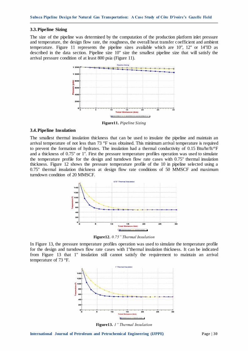
3.3. Pipeline Sizing
The size of the pipeline was determined by the computation of the production platform inlet pressure and temperature, the design flow rate, the roughness, the overall heat transfer coefficient and ambient temperature. Figure 11 represents the pipeline sizes available which are 10", 12" or 14"ID as described in the data section. Pipeline size 10" size the smallest pipeline size that will satisfy the arrival pressure condition of at least 800 psia (Figure 11).
Figure11. Pipeline Sizing
3.4. Pipeline Insulation
The smallest thermal insulation thickness that can be used to insulate the pipeline and maintain an arrival temperature of not less than 73 °F was obtained. This minimum arrival temperature is required to prevent the formation of hydrates. The insulation had a thermal conductivity of 0.15 Btu/hr/ft/°F and a thickness of 0.75" or 1". First the pressure temperature profiles operation was used to simulate the temperature profile for the design and turndown flow rate cases with 0.75" thermal insulation thickness. Figure 12 shows the pressure temperature profile of the 10 in pipeline selected using a 0.75" thermal insulation thickness at design flow rate conditions of 50 MMSCF and maximum turndown condition of 20 MMSCF.
Figure12. 0.75” Thermal Insulation
In Figure 13, the pressure temperature profiles operation was used to simulate the temperature profile for the design and turndown flow rate cases with 1"thermal insulation thickness. It can be indicated from Figure 13 that 1" insulation still cannot satisfy the requirement to maintain an arrival temperature of 73 °F.
Figure13. 1” Thermal Insulation

Subsea Pipeline Design for Natural Gas Transportation: A Case Study of Côte D’ivoire’s Gazelle Field
International Journal of Petroleum and Petrochemical Engineering (IJPPE) Page | 31
For an effective control of the hydrate formation, the system temperature was increased by combining insulation and heating process to meet the requirement of an arrival temperature of 73 °F. The ambient temperature was increased from 50 °F to 80 °F by direct electrical heating system as depicted in Figure 14.
Figure14. 0.75” Thermal Insulation Plus a DEH
3.5. Design Form
Figure 15 is a general overview of the gas pipeline design comprising of riser 1 and riser 2 attached to the main flowline 1 of 10 in. The arrival point at satellite platform indicates SOURCE 1 whereas the boundary node S1 represent the arrival point at processing platform and then the other nodes N1 and N2 represent each end of the pipeline.
Figure15. General View of the Designed Pipeline
Hydrates are predicted to form at a temperature of 65 °F (Figure 10), hence the designed pipeline must be operated above this temperature at all times. The smallest and cost-effective pipeline size that will guaranty the transport of the gas along the desired distance of 30 km with consideration of arrival pressure of at least 800 psi is determined to be 10” (Figure 11), the other two pipeline sizes 12” and 14” ID simulated could be used to achieve the desired results but in other to optimise the design, 10” was selected for the design.
It is clearly estimated that 0.75” thermal insulation thickness (Figure 12), cannot be used to keep the system out of the hydrate region therefore the pipeline was thermally insulated with a 0.75” thermal insulation thickness and heated by the aid of Direct Electrical Heating (DEH) to maintain a steady state pipe temperature above the hydrate formation temperature as shown in Figure 14. The general view of the designed pipeline system with the source from the production platform, through riser 1 (- 30 m), the flow line (30 km long) and up through riser 2 (+ 30 m) to the processing plant is shown in Figure 15. This confirms the impact of pipe insulation in practical design of gas pipelines.
4. CONCLUSION
The following conclusions can be drawn after a series of simulated work using PIPESIM software and data on Gazelle Field in Côte d’Ivoire:
The conditions under which hydrate will form have been simulated and predicted to be 65 °F for the Gazelle Field.
The composition of the product transported is of prime importance within the design process to prevent flow assurance challenges.
Thermal insulation is a critical element in the design and operation of subsea pipelines, and in case of Gazelle Field, Direct Electrical Heating (DEH) was combined with insulation to avoid hydrate formation.

Subsea Pipeline Design for Natural Gas Transportation: A Case Study of Côte D’ivoire’s Gazelle Field
International Journal of Petroleum and Petrochemical Engineering (IJPPE) Page | 32
ACKNOWLEDGEMENT
The authors express their appreciation to the management and staff of University of Mines and
Technology (UMaT) – Tarkwa, Ghana for their support.
Nomenclature
Z = Compressibility factor for gas, dimensionless,
ρ = density, lbm/ft3,
V = velocity, ft/sec,
g = gravitational constant, 32.2 ft/sec2,
f = Moody friction factor, dimensionless,
L = pipe length, ft,
Lm = length, miles,
d = pipe diameter, ft,
ΔP = pressure drop, psi,
μ = viscosity, lbm/ft-sec.
SG = specific gravity of liquid relative to water (water = 1),
S = specific gravity of gas at standard conditions relative to air (molecular weight divided by 29),
Qg = gas-flow rate, MMscf/D,
Ql = liquid flow rate, B/D,
W = rate of flow, lbm/sec
P1 = upstream pressure, psia
P2 = downstream pressure, psia.
ΔhW = pressure loss, inches of water,
A = cross-sectional area of pipe, ft2,
V1 = specific volume of gas at upstream conditions, ft3/lbm,
P = operating pressure, psia,
R = gas/liquid ratio, ft3/bbl,
T = operating temperature, °R,
T1 = temperature of gas at inlet, °R,
E = efficiency factor (new pipe: 1.0; good operating conditions: 0.95; average operating conditions: 0.85)
Assumptions
1000
103.0
6.31d
df
T = 520 °R,
P1 = 15 psia,
Z = 1.0, and
ΔP = less than 10 % of P1.
REFERENCES
[1] Liang F, Ryvak, M., Sayeed, S. and Zhao, N “The Role of Natural Gas as a Primary fuel in the near
Future, including comparisons of acquisition, transmission and waste handling costs of as with competitive
alternatives”, Chemical Central Journal, Vol 6 (Suppl 1): S4. doi: 10.1186/1752-153X-6-S1-S4, pp. 1-37,
(2012).
[2] Fei, Q., Guarnieri, M.T., Tao, L., Laurens, L.M.L., Dowe, N. and Pienkos , P. T. “Bioconversion of natural
gas to liquid fuel: Opportunities and challenges”, Biotechnology Advances, Vol. 32, Issue 3, May –June,
pp. 596-614, (2014).

Subsea Pipeline Design for Natural Gas Transportation: A Case Study of Côte D’ivoire’s Gazelle Field
International Journal of Petroleum and Petrochemical Engineering (IJPPE) Page | 33
[3] Singh, R. R. and Nain, P K S “Optimization of Natural Gas Pipeline Design and Its Total Cost Usin g GA”, International Journal of Scientific and Research Publications, Vol. 2, Issue 8, August, (2012).
[4] Cheng, F, “Pipeline Engineering”, Unpublished Lecture Notes, University of Calgary, Alberta, Canada, pp. 1-11, (2010).
[5] Liu, H. “Pipeline Engineering Handbook” CRC Press LLC, ISBN 0-203-59487-8, 422pp, (2003).
[6] Nayyar, L. M. “Piping Handbook”, The McGraw-Hill Companies Inc. Handbooks, 7th Edition, 2483pp,
(2003).
[7] Hamzah, N. S. B. “Newton Loop-Node Analysis Study on Gas Pipeline Network”, Unpublished BSc Thesis, Universiti Malaysia Pahang, 26pp, (2010).
[8] Ameripour, S. “Prediction of Gas Hydrate Formation Conditions in Production and Surface Facilities”, Unpublished MSc Project Report, Texas A&M University, 79pp, (2005).
[9] Sumer, B.M. and Fredsoe, J, “A Review of Wave/Current-Induced Scour around Pipelines”, 23rd
International Conference on Coastal Engineering, pp. 1-14, (1992).
[10] Obanijesu, E. O., Pareek, V. and Tade, M. O. “Hydrate Formation and its Influence on Natural Gas
Pipeline Internal Corrosion Rate”, SPE Oil and Gas India Conference and Exhibition, Mumbai, India, 20-22 January, pp. 1-11, (2010).
[11] Okologume, W and Appah, D. “Analysing Thermal Insulation for Effective Hydrate Prevention in
Conceptual Subsea Pipeline Design”, International Journal of Current Engineering and Technology, Vol. 5, No. 4, pp. 2 – 6, (2015).
[12] Guo, Y. and Zhang, H. “A Prediction Method of Natural Gas Hydrate Formation in Deepwater Gas Well and its Application”, Petroleum, Vol. 2, Issue 3, September, pp. 296-300, (2016).
[13] Vinatovskaja, T. “Cold Flow in the Arctic: A Feasibility Study”, Unpublished MSc Thesis, University of
Stavanger, 91pp, (2015).
[14] Patni, S. and Janardhan, J. “Service-Line Option for Hydrate Management in Single Flowline Tieback”, SPE Annual Technical Conference and Exhibition, 9-12 October, Dallas, Texas, pp. 1-7, (2005).
[15] Bai, Y. and Bai, Q. “Subsea Pipeline and Risers Handbook”, Elsevier Publication, 1st Ed., 812pp, (2005).
[16] Christiansen, H, E. “Rate of Hydrate Inhibitor in Long Subsea Pipelines”, Unpublished MSc Thesis, Norwegian University of Science and Technology, 117pp, (2012).
[17] Boyun, G., William, C.L., Ali, G. “Petroleum Production Engineering: A Computer-Assisted Approach”,
Gulf Professional Publishing, ISBN: 9780750682701, 312pp, (2007).
[18] Miranda, J. L. H. and Lopez, L. A. A “Piping Design: The Fundamentals”, Short Course on Geothermal
Drilling, Resource Development and Power Plants”, organized by UNU-GTP and LaGeo, in Santa Tecla, El Salvador, January 16-22, pp. 1-15, (2011).
[19] Anon, (2013), “Gazelle Field - Offshore Technology”, www.offshore-technology.com/projects/gazelle-
field/, Accessed: January, 10, 2018.
[20] Anon, (2011), “Ivory Coast: Rialto, Petroci Submit Gazelle Field Development Plan”, www.offs
horeenergytoday.com/ivory-coast-rialto-petroci-submit-gazelle-field-development-plan/,Accessed:January, 10, 2018.
[21] Anon, (2014), “Gazelle - SubSeaIQ - Offshore Field Development Projects”, www.subseaiq.com/ data/
Project.aspx? project_id=1040, Accessed: January, 10, 2018.
[22] Anon, (2014), “Azonto Petroleum – Onto Better Things”, www.edisoninvestmentresearch.com/? ACT=18&ID=12071&LANG=, Accessed: January 11, 2018.
[23] Osokogwu, U., Emuchay, D., Ottah, G., Aliu, S. & Ajienka, J. A. “Improved Method of Predicting and
Monitoring Flow Assurance Problems in the Niger Delta using PROSYS”, SPE Nigeria Annual
International Conference and Exhibition, Lagos, Nigeria, 05-07 August, pp. 1-8, (2014).
[24] Pham, S.T., Truong, M.H. and Pham, B.T. “Flow Assurance in Subsea Pipeline Design for Transportation
of Petroleum Products” Open Journal of Civil Engineering, Vol. 7, pp. 311-323, https://doi.org/ 10.4236/ojce.2017.72021, (2017).
[25] Akpabio, N. G. “Hydrate Prevention in Subsea Natural Gas Production” TPG4510 Petroleum Production
Specialization Project, Norwegian University of Science and Technology, 54pp, (2012).
[26] Phil, H. “Oil and Gas Pipelines: Yesterday and Today”, American Society of Mechanical Engineers (ASME), 9pp, (2007).
[27] Sadafule, S. and Patil, K. D. “Study on Effect of Insulation Design on Thermal-Hydraulic Analysis: An
Important Aspect in Subsea Pipeline Designing”, International Journal of Petroleum Engineering and
Technology, Vol. 2, Issue 4, pp. 33-45, (2014).
[28] Broni-Bediako, E., Amorin, R. and Bavoh, C. B. “Gas Hydrate Formation Phase Boundary Behaviour of
Synthetic Natural Gas Systems at Keta Field of Ghana”, 4th UMaT Biennial International Mining and Mineral Conference, pp. 19-24, (2016).
Subsea Pipeline Design for Natural Gas Transportation: A Case Study of Côte D’ivoire’s Gazelle Field
International Journal of Petroleum and Petrochemical Engineering (IJPPE) Page | 34
[29] Liu, Z. “Study of Hydrate Deposition and Sloughing of Gas -Dominated Pipelines Using Numerical and Analytical Models”, Unpublished PhD Dissertation, Colorado School of Mines, USA, 137pp, (2017).
[30] Austvik, T. “Hydrate Formation and Behaviour in Pipes” Unpublished PhD dissertation, Norwegian University of Science and Technology, Trondheim, Norway, 280pp, (1992).
[31] Bolkeny, I. and Konyha, J. “Prevention of Hydrate Formation on Gas Well”, Research Institute of Applied
Earth Sciences, University of Miskolc, pp. 1-8.
[32] Ashan, S. “Preventing Hydrate Formation in Gas Transporting Pipe Lines with Synthetic Inhibitors”,
International Journal of Chemistry, Vol. 1, pp. 1-6, (2013).
[33] Tohidi, B. “Advances in Avoiding Gas Hydrate Problems”, Centre for Gas Hydrates Research &
Hydrafact Ltd, Institute of Petroleum Engineering, Heriot-Watt University, UK, pp. 1-47, (2014).
[34] Wu, M., Wang, S. and Liu H. “A Study on Inhibitors for the Prevention of Hydrate Formation in Gas
Transmission Pipeline”, Journal of Natural Gas Chemistry, Vol. 16, Issue 1, pp. 81-85, (2007).
[35] Hashem, A. A. “Oil and Gas Pipeline Design, Maintenance and Repair Course”, Mining, Petroleum &
Metallurgical Engineering Department, Faculty of Engineering, Cairo University, 15pp, (2006).
[36] Nasr, G. G. and Connor, N. E. “Natural Gas Engineering and Safety Challenges: Downstream Process,
Analysis, Utilization and Safety”, Springer International Publishing, ISBN: 978-3-319-08948-5, 402pp, (2014).
[37] Mohitpour, M., Golshan, H., Murray, A. “Pipeline Design & Construction: A Practical Approach”, 3 rd
Edition, ASME Press, New York, 656pp, (2007).
[38] Anon, (2017), Petromin Pipeliner: Combating Corrosion – Hydrocarbon Asia, 16th Asian Oil, Gas &
Petrochemical Engineering Exhibition, 11th -13th, July, Kuala Lumpur Convention Centre, Malaysia, pp. 1-56, (2017).
[39] Anon, (2015), “Pressure drop evaluations along Pipelines”, https://petrowiki.org/Pressure_drop_
evaluation_along_pipelines#cite_ref-r1_1-0, Accessed: January 5, 2018.
[40] Bhatia, A. “Overview of Insulation Materials Course”, Continuing Education and Development, Inc. 9 Greyridge, Farm Court Stony Point, NY 10980, 64pp, (2013).
[41] Jackson, A., Jackson, P., Wan, E. and Hegdal, J. P. “A Novel Thermal Insulation System for Bonded
Subsea Single Pipe Wet Insulation Applications”, 18th BHR Conference on Pipeline Protection, Antwerp,
Belgium, 4th to 6th November, pp. 1-17, (2009).
[42] Anon, (2018), “The Benchmark for Wet Insulation Systems”, www.trellborg.com/offshore. Accessed: January 2, (2018).
[43] Zulkefli, N. H. and Pao, W. “Optimum Thermal Insulation Design for Subsea Pipeline Flow Assurance”, Technical Report, Universiti Teknologi PETRONAS, Malaysia, 8pp, (2016).
AUTHORS’ BIOGRAPHY
Solomon Adjei Marfo, is a Lecturer at the Petroleum Engineering Department of University of Mines and Technology, Tarkwa, Ghana. He holds PhD in Petroleum Engineering from the University of Port Harcourt, Nigeria, MEng Degree in Mining (Petroleum Engineering) from the University of Belgrade, Serbia and BSc in Chemical Engineering from the Kwame Nkrumah University of Science and Technology, KNUST, Kumasi, Ghana. He is a member of the Society of Petroleum
Engineers (SPE), a Registered Environmental Specialist (RES) with the National Registry of Environmental Professionals (NREP) of USA. His research interests include sand and water control in oilfields using chemicals, agro-waste and local materials evaluation for oilfields application.
Prince Opoku Appau, is an MSc candidate at the Research Institute of Enhanced Oil Recovery of the China University of Petroleum (Beijing), majoring in Petroleum and Natural Gas Engineering. He holds BSc degree in Petroleum Engineering from the University of Mines and Technology (UMaT), Ghana. He is also a member of Society of Petroleum Engineers (SPE). His research interests include drilling fluids, rock petrophysics, reservoir engineering, EOR and natural gas engineering.
Citation: S. A. Marfo, et.al. (2018). “Subsea Pipeline Design for Natural Gas Transportation: A Case Study
of Côte D’ivoire’s Gazelle Field”, International Journal of Petroleum and Petrochemical Engineering (IJPPE),
4(3), pp.21-34, DOI: http://dx.doi.org/10.20431/2454-7980.0403003
Copyright: © 2018 Authors. This is an open-access article distributed under the terms of the Creative Commons
Attribution License, which permits unrestricted use, distribution, and reproduction in any medium, provided the
original author and source are credited