substation lv cables, conduits, trenches and pits · third party iusa has the same meaning as...
TRANSCRIPT

Substation LV Cables, Conduits, Trenches and Pits
Document Number: 1-11-FR-06
VERSION 1.0 June 2018

This functional requirement document is in line with the organisation's 1-11-ACS-06 Substation LV Cables, Conduits, Trenches and Pits Asset Class Strategy
Intellectual property rights and disclaimer
This document is published in accordance with the requirements of Chapter 5 of the National Electricity Rules (NER). It is a functional requirement document only and is not intended to contain any comprehensive or project specific designs, specifications or other information. Whilst care has been taken to ensure that the contents of this document are accurate, ElectraNet Pty Limited (ElectraNet) does not represent or warrant that the information contained in this document is complete, accurate or adequate in any respect. ElectraNet reserves the right to amend this document at any time without notice to any person.
The user must carefully examine and check the information contained in this document and carry out its own independent technical and legal assessment and due diligence to ensure that the information in this document is used appropriately and that in doing so, all requirements (including requirements at law) are satisfied. For the avoidance of any doubt, the publication of this document does not limit or detract from the user’s obligations at law, and does not and will not give rise to any claim (including, without limitation, in contract, tort, equity, under statute or otherwise) against ElectraNet or any of its ‘Associates’ (as that term is defined in Corporations Act 2001 (Cth)).
All intellectual property rights (including without limitation any copyright, patents, logos, designs, circuit layouts, trademarks, moral rights and know how) in the whole and every part of this document are owned by or licenced to ElectraNet. Except as expressly provided in Chapter 5 of the NER or with the prior written consent of ElectraNet, the contents of this document cannot be used, transferred, copied, modified or reproduced in whole or in part in any manner or form or in any media.
© ElectraNet Pty Limited. All rights reserved
Substation LV Cables, Conduits, Trenches and Pits l Document No: 1-11-FR-06
Security Classification: Public WHEN PRINTED THIS DOCUMENT IS UNCONTROLLED
Date: June 2018
Version: 1.0 ©ElectraNet Pty Limited 2018 – all rights reserved
Page 3 of 14
Contents
1. Definitions .................................................................................................................. 4
2. Purpose and Scope ................................................................................................... 6
3. Referenced Documents ............................................................................................ 7
4. LV Cables ................................................................................................................... 8 4.1 Introduction ................................................................................................................... 8 4.2 Design and Construction ............................................................................................. 8
4.2.1 Cable ....................................................................................................................... 8 4.2.2 EMC Requirements ................................................................................................. 9 4.2.3 Cable Installation ....................................................................................................10 4.2.4 Trenches ................................................................................................................10 4.2.5 Electrical Conduits ..................................................................................................11 4.2.6 Cable Pits ...............................................................................................................12
4.3 Testing Requirements .................................................................................................13 4.3.1 Cable ......................................................................................................................13
Substation LV Cables, Conduits, Trenches and Pits l Document No: 1-11-FR-06
Security Classification: Public WHEN PRINTED THIS DOCUMENT IS UNCONTROLLED
Date: June 2018
Version: 1.0 ©ElectraNet Pty Limited 2018 – all rights reserved
Page 4 of 14
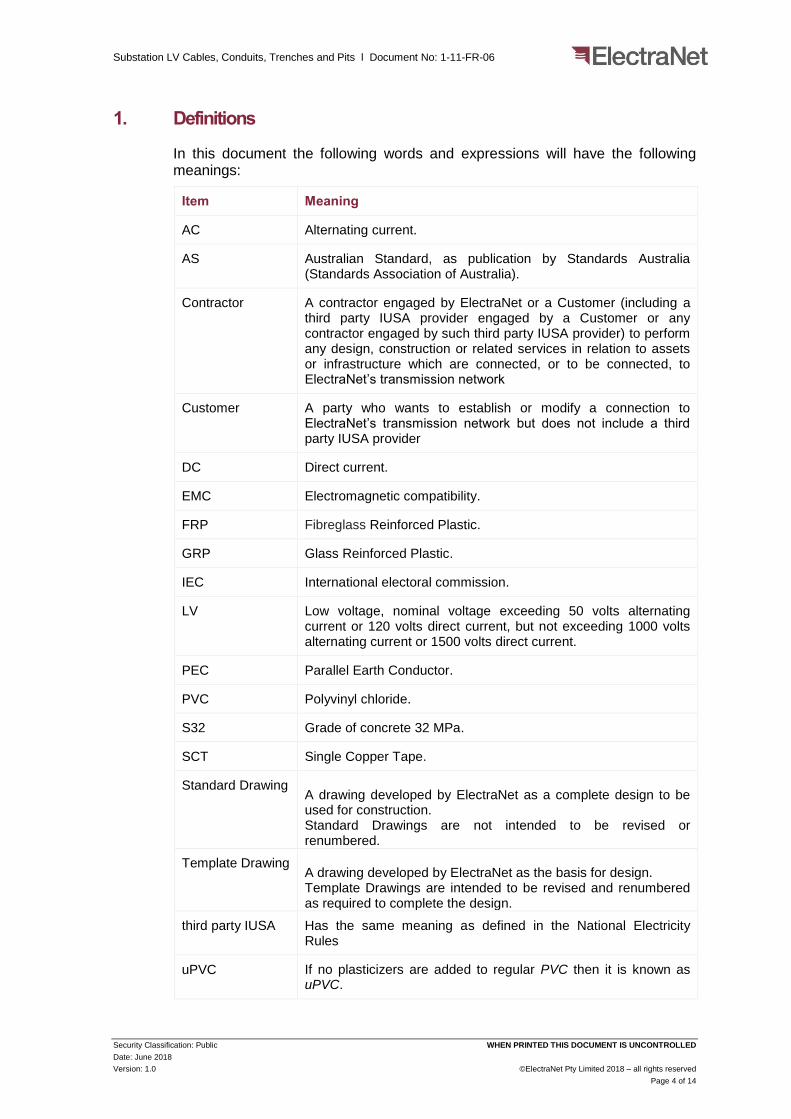
1. Definitions
In this document the following words and expressions will have the following meanings:
Item Meaning
AC Alternating current.
AS Australian Standard, as publication by Standards Australia (Standards Association of Australia).
Contractor A contractor engaged by ElectraNet or a Customer (including a third party IUSA provider engaged by a Customer or any contractor engaged by such third party IUSA provider) to perform any design, construction or related services in relation to assets or infrastructure which are connected, or to be connected, to ElectraNet’s transmission network
Customer A party who wants to establish or modify a connection to ElectraNet’s transmission network but does not include a third party IUSA provider
DC Direct current.
EMC Electromagnetic compatibility.
FRP Fibreglass Reinforced Plastic.
GRP Glass Reinforced Plastic.
IEC International electoral commission.
LV Low voltage, nominal voltage exceeding 50 volts alternating current or 120 volts direct current, but not exceeding 1000 volts alternating current or 1500 volts direct current.
PEC Parallel Earth Conductor.
PVC Polyvinyl chloride.
S32 Grade of concrete 32 MPa.
SCT Single Copper Tape.
Standard Drawing A drawing developed by ElectraNet as a complete design to be used for construction. Standard Drawings are not intended to be revised or renumbered.
Template Drawing A drawing developed by ElectraNet as the basis for design. Template Drawings are intended to be revised and renumbered as required to complete the design.
third party IUSA Has the same meaning as defined in the National Electricity Rules
uPVC If no plasticizers are added to regular PVC then it is known as uPVC.

Substation LV Cables, Conduits, Trenches and Pits l Document No: 1-11-FR-06
Security Classification: Public WHEN PRINTED THIS DOCUMENT IS UNCONTROLLED
Date: June 2018
Version: 1.0 ©ElectraNet Pty Limited 2018 – all rights reserved
Page 5 of 14
Item Meaning
XLPE Cross-linked polyethylene.
Substation LV Cables, Conduits, Trenches and Pits l Document No: 1-11-FR-06
Security Classification: Public WHEN PRINTED THIS DOCUMENT IS UNCONTROLLED
Date: June 2018
Version: 1.0 ©ElectraNet Pty Limited 2018 – all rights reserved
Page 6 of 14
2. Purpose and Scope
This document states the functional requirements with regard to substation LV cables and integration of substation LV cables into a substation. The document addresses the substation cable selection for AC and DC applications as well as the design and construction requirements associated with LV cables such as conduits, pits, trenching, civil works and cable terminations.
All cable procurement and installation practices must follow the standards and guidelines listed in section 4 of this document.
The following cables and their applications are considered:
a) AC cables in substations: 400 V and 230 V cables for the connection to the substation AC three phase and single phase loads;
b) DC cables in substations: 110 V and 48 V cables for the connection to the protection, control, SCADA and telecommunication type loads; and
c) All the fibre optic and signal cables.

Substation LV Cables, Conduits, Trenches and Pits l Document No: 1-11-FR-06
Security Classification: Public WHEN PRINTED THIS DOCUMENT IS UNCONTROLLED
Date: June 2018
Version: 1.0 ©ElectraNet Pty Limited 2018 – all rights reserved
Page 7 of 14
3. Referenced Documents
The table below lists applicable legislations, standards, referenced documents:
Legislation
SAEA Electricity Act 1996 (SA)
SAER South Australia Electricity (General) Regulations 2012 (SA) under the SAEA
NER National Electricity Rules
ETC Electricity Transmission Code TC/08
SAA HB59:1994 Ergonomics - The human factor A practical approach to work systems design
International Standards
AS/ISO 1000:1998 The international system of units (SI) and its applications.
AS/NZS 1477:2006 PVC pipes and fittings for pressure applications
AS/NZS 2053.1:2001 (R2016) Conduits and fittings for electrical installations - General requirements
AS/NZS 2053.2:2001 (R2016) Conduits and fittings for electrical installations - Rigid plain conduits and fittings of insulating material
AS/NZS 3008.1.1:2017 Electrical Installation - Selection of Cables - Part 1.1: Cables for alternating voltages up to and including 0.6/1 kV - Typical Australian installation conditions
AS 3996 :2006 Access covers and grates
AS/NZS 5000.1:2005 (R2017) Electric cables – Polymeric insulated
AS/NZS 5000.3:2003 (R2017) Electric cables for control and protection circuits – Multicore control cables.
IEC 61000-5-1 1996-12 Electromagnetic compatibility EMC – Part 5 Installation and mitigation guidelines Section 1: General considerations
IEC 61000-5-2 1997-11 Electromagnetic compatibility EMC – Part 5 Installation and mitigation guidelines Section 2: Earthing and cabling
ElectraNet’s Documentation
1-11-FR-01 Substation Earthing
1-09-FR-027 Circuitry

Substation LV Cables, Conduits, Trenches and Pits l Document No: 1-11-FR-06
Security Classification: Public WHEN PRINTED THIS DOCUMENT IS UNCONTROLLED
Date: June 2018
Version: 1.0 ©ElectraNet Pty Limited 2018 – all rights reserved
Page 8 of 14
4. LV Cables
4.1 Introduction
4.1.1.1 All multicore cable (including fibre optic cable) and associated terminations are to be quantified in accordance with 1-09-FR-27 Circuitry; however, they are to be procured and installed in accordance with the requirements of this document. AC and DC cabling sharing the same trenches, conduits or cable ladders must be installed at an insulation level and a depth to ensure that the intent of the AS/NZ 3000 Wiring Rules with respect to safety and reliable operation is met.
4.1.1.2 Separate cables must be used for:
a) X and Y protection sets (Set 1 and Set 2);
b) X and Y DC systems (Set 1 and Set 2);
c) AC signals from instrument transformers and DC monitoring functions;
d) AC and DC power distribution for all equipment;
e) AC and DC control functions; and
f) DC control and DC monitoring for SCADA functions.
4.2 Design and Construction
4.2.1 Cable
4.2.1.1 Cables must be suitable for laying direct in the ground, in concrete cable trenches, conduits, exposed cable ducts, in the open, on ladders, trays, exposed to direct sunlight, or immersed in water for extended periods.
4.2.1.2 The cables types approved by ElectraNet are detailed in the latest revision of ElectraNet’s Standard Drawing 510 STD/257-001, which covers all indoor and outdoor applications.
4.2.1.3 AC and DC cables must be 0.6/1 kV rated.
4.2.1.4 Cable conductors must be copper. For multi-core cable applications multi-stranded conductors must be used.
4.2.1.5 Power cables are classified for either indoor or outdoor application.
4.2.1.6 All cables must be protected by a protection device appropriately graded within the network.
4.2.1.7 Indoor type cables must be not screened and the type of cable must be selected from ElectraNet’s Standard Drawing.
4.2.1.8 Outdoor type cables must be screened and the type of cable must be selected from ElectraNet’s Standard Drawing.
4.2.1.9 Cables for outdoor application must be either PVC or XLPE insulated according to specific requirement.

Substation LV Cables, Conduits, Trenches and Pits l Document No: 1-11-FR-06
Security Classification: Public WHEN PRINTED THIS DOCUMENT IS UNCONTROLLED
Date: June 2018
Version: 1.0 ©ElectraNet Pty Limited 2018 – all rights reserved
Page 9 of 14
4.2.1.10 For outdoor cables the metallic layer must be SCT according to clause 9 ‘Metallic Layers’ in AS/NZS 5000.1:R2017 for EMC considerations. Additional layers may be added to meet any site-specific safety and protection requirements of the cable if required.
4.2.1.11 Multicore cables are required for use in control, protection, instrumentation and power/lighting circuits in switchyards and substations throughout South Australia.
4.2.1.12 Power cables for low voltage AC application in respect to conductors, insulation, configuration, length of lay of cores, fillers, binders, binder tapes, identification of cores, marking, construction and dimensions must be in accordance with AS/NZS 5000.1:2005.
4.2.1.13 Cables must be suitably sized and rated for load, fault and thermal considerations (i.e. I²t suitable) for the rating of the associated primary and back up protection associated with the circuits. The voltage drop calculations must be in accordance with AS 3008.
4.2.1.14 The neutral wires, associated with power cables, must be sized for the maximum fault level calculated for the AC supply system and the selection of the neutral conductor must be in accordance with AS 3000.
4.2.1.15 Protection, control, data, fire alarm cables must be run separately from the substation AC station supplies cables.
4.2.1.16 Cables of low voltage circuits may be enclosed in the same wiring system as cables of extra-low voltage circuits, but only if the requirements of AS/NZS 3000 are met.
4.2.2 EMC Requirements
4.2.2.1 Adherence to the recommended practices of Australian Standards and IEC standards for acceptable cabling to EMC standards is required.
4.2.2.2 All cabling that enters metallic enclosures, such as marshalling kiosks, plant mechanism boxes or other cubicles outside the control building must pass through gland plates and must use EMC glands. The EMC glands must have the facility to terminate the cable screens and form a circumferential connection of the screen to the gland plate which is in turn connected to the metallic enclosure.
4.2.2.3 An EMC conductor (also named PEC) must be installed in accordance with all of the requirements described in document 1-11-FR-01 Substation Earthing.
4.2.2.4 The gland plates must be made out of brass and when not supplied with the equipment (by the equipment vendor) they must be retrofitted by the Contractor on site.
4.2.2.5 The EMC conductor must be sized in accordance with the requirements described in document 1-11-FR-01 Substation Earthing.
Substation LV Cables, Conduits, Trenches and Pits l Document No: 1-11-FR-06
Security Classification: Public WHEN PRINTED THIS DOCUMENT IS UNCONTROLLED
Date: June 2018
Version: 1.0 ©ElectraNet Pty Limited 2018 – all rights reserved
Page 10 of 14
4.2.3 Cable Installation
4.2.3.1 The cables must be installed in plastic conduits or in concrete trenches as described in the project specifications.
4.2.3.2 Conduits must be provided in, or adjacent to, foundations to cater for the installation of the multicore cables, and various power cables as required. Conduits must extend a minimum of 50 mm above the top of the footing.
4.2.3.3 Typical sizes for conduits and trenches and cable pits are outlined in ElectraNet’s Standard Drawings and Template Drawings.
4.2.3.4 For cables installed inside the substation the minimum installation depth when installed in conduits must be in accordance to AS 2067, with associated risk assessments being carried out, and must cater for site specific requirements.
4.2.3.5 For all low voltage cables that leave the substation and will travel outside the substation perimeter fence they must be installed in accordance with the requirements of AS 3000 which covers the burial depth, mechanical protection and cable marking requirements.
4.2.3.6 When installed in plastic conduits, they must be Orange Unplasticised PVC type, with the wall rated as Heavy Duty. Wafer type PVC must not be used.
4.2.3.7 When exiting from the underground, the orange conduit must be protected with white paint from the direct sun exposure.
4.2.3.8 The main substation auxiliary supply cables, i.e., from station auxiliary supply transformers to the main AC changeover board, must use independent routes to all other substation multicore cables.
4.2.3.9 For outdoor applications, fibre optic cables must be installed in dedicated telecommunications conduits following routes as described by the project specification.
4.2.3.10 All cores are to be terminated. Spare cores, at both ends of the cable must be shorted and earthed using dedicated green/yellow earthing terminals.
4.2.3.11 Cables must be identified at both ends of the cable run as well as both inside and outside each gland plate the cables pass through.
4.2.3.12 In outdoor applications cables running from ground level to equipment termination boxes must be attached to the equipment support structure, or cable ladders, using stainless steel bands.
4.2.3.13 Jointing of cables is not allowed.
4.2.3.14 A point to point test must be conducted for every cable terminal.
4.2.4 Trenches
4.2.4.1 Cable trenches must be designed in accordance with the ElectraNet’s Standard Drawings and Template Drawings.
Substation LV Cables, Conduits, Trenches and Pits l Document No: 1-11-FR-06
Security Classification: Public WHEN PRINTED THIS DOCUMENT IS UNCONTROLLED
Date: June 2018
Version: 1.0 ©ElectraNet Pty Limited 2018 – all rights reserved
Page 11 of 14
4.2.4.2 Cables laid in concrete cable trenches must exit through conduits to the equipment termination boxes or through the knock-out holes in the trench, and a bellmouth must be used for each of these exit points.
4.2.4.3 Concrete for all structural purposes must have a strength grade not less than S32.
4.2.4.4 Trenches must be constructed from cast in-situ concrete, pre-cast units with formwork ‘fair finish’, or other materials like GRP or FRP as required by the cable designer and approved by ElectraNet.
4.2.4.5 Metallic covers must be earthed.
4.2.4.6 Cable trench covers must be designed to withstand the load of maintenance vehicles when located in the trafficable areas and rated in accordance with Table 3.1 of AS3996.
4.2.4.7 A control cable trench must have a minimum slope of 1:200 for drainage purposes and must have a sump at its lowest level, or be connected to the substation stormwater drainage system. The invert level must be calculated so that the trench top is nominally 30 mm above finished site level. Trenches must be sloped to prevent the entry of water into the building; in cases where this is impossible, supplementary sumps and drainage of the trench must be provided. The design of the trenching system must prevent the pooling of water.
4.2.4.8 Cable trench thickness of sides must be designed according to loading and cover type. A minimum trench thickness of 150 mm is recommended.
4.2.4.9 The overall size of cable trenches must be determined on the basis of the proposed installation, lifting of the trench lids considerations plus any future works that are identified on the ultimate layout.
4.2.4.10 The trenches must be built with expansion joints spaced at regular intervals with spacing dependent on the type site soil conditions but not exceeding 10 metres.
4.2.4.11 Where oil filled transformers are installed in a substation, fire stops or other approved barriers must be provided in the trenches to ensure that burning oil cannot enter or flow under a building.
4.2.5 Electrical Conduits
4.2.5.1 Conduit types and sizes must be in accordance with AS/NZS 2053.
4.2.5.2 Jointing materials and methods for conduits must be consistent with the conduit material and in accordance with the manufacturer's instructions.
4.2.5.3 All conduits and conduits bends sizes greater than 150 mm nominal diameter must be Class 12 Pressure Pipe in accordance with AS1477:2006 and AS2053:1995.
4.2.5.4 Telecommunication conduits selection and installation must be as per the ElectraNet design standards, where 100 mm diameter white conduits must be used. A minimum of two conduits must be installed for each “telecommunications cable route” to cater for future expansion.

Substation LV Cables, Conduits, Trenches and Pits l Document No: 1-11-FR-06
Security Classification: Public WHEN PRINTED THIS DOCUMENT IS UNCONTROLLED
Date: June 2018
Version: 1.0 ©ElectraNet Pty Limited 2018 – all rights reserved
Page 12 of 14
4.2.5.5 All conduits must have an 8 mm diameter rot-proof draw rope installed and suitably restrained to prevent accidental withdrawal into or out of the conduit.
4.2.5.6 Buried conduits must be laid in straight lines and to even falls.
4.2.5.7 Level conduit runs must be laid with nominal falls to create high point midway in each run to allow moisture to run back to the cable-pit chambers.
4.2.5.8 Wherever possible service conduit systems must be watertight and the ingress of vermin must be prevented.
4.2.5.9 Pipework conduits within 1.5 m, measured horizontally, of the edge of a foundation or within the 45° spread of load line from the underside of a foundation must be encased in S20 concrete.
4.2.5.10 Conduits must be sealed when entering bunded areas.
4.2.5.11 The cable capacity of a conduit or pipe must be determined by its cross sectional area with compensation for the number of bends or level changes and generally must not exceed 40% of conduit area. Refer AS/NZS 3000 for requirements.
4.2.6 Cable Pits
4.2.6.1 Cable pits must be sized to accommodate the largest cable bending radius and also to allow physical access to install cables.
4.2.6.2 Cable pits must be designed in accordance with the ElectraNet’s Standard Drawings and Template Drawings.
4.2.6.3 Telecommunication cable pits must be designed in accordance with ElectraNet’s design standards.
4.2.6.4 Pits must be self-draining. Substation runoffs must be discharged from the site and buried pipes and pits must be integrated in the overall drainage infrastructure.
4.2.6.5 Inspection or cable pits must be constructed to avoid the ingress of groundwater. The floors must slope to a sump 300 mm square by 150 mm deep.
4.2.6.6 The invert of the lowest duct within an inspection or draw pit must be not less than 150 mm above the floor.
4.2.6.7 A bellmouth must be installed where cable conduits enter the cable pits. If this is not possible then the concrete edges must be rounded to a minimum radius of 20 mm.
Substation LV Cables, Conduits, Trenches and Pits l Document No: 1-11-FR-06
Security Classification: Public WHEN PRINTED THIS DOCUMENT IS UNCONTROLLED
Date: June 2018
Version: 1.0 ©ElectraNet Pty Limited 2018 – all rights reserved
Page 13 of 14
4.3 Testing Requirements
4.3.1 Cable
4.3.1.1 The cable must be tested in accordance with the requirements of AS/NZS 5000.3:2003 and test certificates detailing the results of all tests carried out by the Contractor must be submitted to ElectraNet in text recognised PDF. Type test certificates must be submitted as agreed with ElectraNet. Routine and special test certificates must be submitted within one week of testing or as agreed with ElectraNet. Test certificates must clearly show the Contractor’s official order number and the location to which the cable, covered by such certificate, was dispatched.
4.3.1.2 Each consignment may be subject to inspection and testing by ElectraNet after delivery and before acceptance. Should the cable fail to satisfy ElectraNet’s inspection and tests to the standards specified in AS/NZS 5000.3:2003, it will be rejected and the Contractor will be notified of such rejection and the reason therefore.