sulfate by flow injection analysis (fia) - ezkem.com solution 3000 1 part #a001978 publication...
TRANSCRIPT

Flow Solution 30001
Part #A001978Publication 12470501
Sulfate by FIA
����������
Sulfate by Flow Injection Analysis (FIA)
(Cartridge Part #A001569)
1.0 Scope and Application
1.1 This method is used for the determination of sulfate in drinking water, surface water, saline water,and domestic and industrial waste (References 15.4 and 15.5).
1.2 The Method Detection Limit (MDL) of this method is 1.61 mg/L sulfate. The applicable range ofthe method is 2.0–200 mg/L sulfate. The range may be extended to analyze higher concentrationsby sample dilution.
2.0 Summary of Method
2.1 Within the pH range of 2.5–3.0, sulfate ions react with a barium-methylthymol blue (BaMTB)complex to form barium sulfate (BaSO
4) and free methylthymol blue (MTB). The analytical
stream is then made highly basic (pH 12.5–13.0). At this pH, the absorbance maximum for theBaMTB complex is 610 nm while that of free MTB is 460 nm. Given that the molar concentra-tions of barium and MTB are approximately equal and that the maximum sulfate concentration tobe measured does not exceed the concentration of the BaMTB complex, the sulfate concentrationis directly proportional to the free MTB concentration measured at 460 nm.
BaMTB4- + SO42- BaSO
4 + MTB6-
The sulfate calibration curve is nonlinear. Colovos et al. (Reference 15.1) have attributed this tothe formation of a binuclear BaMTB complex and to impurities in commercially available MTBdye.
2.2 The quality of the analysis is assured through reproducible calibration and testing of the FlowInjection Analysis (FIA) system.
pH 2.5–3.0

Flow Solution 30002
Part #A001978Publication 12470501
Sulfate by FIA
2.3 A general flow diagram of the FIA system is shown below (see Section 17.0 for a detailed flowdiagram).
3.0 Definitions
Definitions for terms used in this method are provided in Section 16.0, “Glossary of Definitions andPurposes.”
4.0 Interferences
4.1 Multivalent cations such as calcium, magnesium, and aluminum are removed with a cationexchange column. Neutralize samples with pH values less than 2 to prevent the elution of cationsfrom the ion exchange resin.
4.2 Filter or centrifuge turbid samples prior to analysis.
5.0 Safety
5.1 The toxicity or carcinogenicity of each compound or reagent used in this method has not beenfully established. Each chemical should be treated as a potential health hazard. Exposure to thesechemicals should be reduced to the lowest possible level.
5.2 For reference purposes, a file of Material Safety Data Sheets (MSDS) for each chemical used inthis method should be available to all personnel involved in this chemical analysis. The prepara-tion of a formal safety plan is also advisable.
5.3 The following chemicals used in this method may be highly toxic or hazardous and should behandled with extreme caution at all times. Consult the appropriate MSDS before handling.
5.3.1 Ammonium Chloride, NH4Cl (FW 53.49)
5.3.2 Ammonium Hydroxide, NH4OH (FW 35.05)
5.3.3 Barium Chloride Dihydrate, BaCl2•2H
2O (FW 244.28)
5.3.4 Chloroform, CHCl3 (FW 119.38)
������
������
���������
���� �� ����
��� ��������� ��
��������������������
Flow Solution 30003
Part #A001978Publication 12470501
Sulfate by FIA
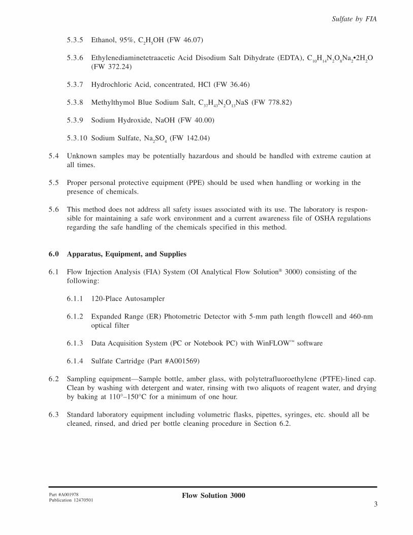
5.3.5 Ethanol, 95%, C2H
5OH (FW 46.07)
5.3.6 Ethylenediaminetetraacetic Acid Disodium Salt Dihydrate (EDTA), C10
H14
N2O
8Na
2•2H
2O
(FW 372.24)
5.3.7 Hydrochloric Acid, concentrated, HCl (FW 36.46)
5.3.8 Methylthymol Blue Sodium Salt, C37
H43
N2O
13NaS (FW 778.82)
5.3.9 Sodium Hydroxide, NaOH (FW 40.00)
5.3.10 Sodium Sulfate, Na2SO
4 (FW 142.04)
5.4 Unknown samples may be potentially hazardous and should be handled with extreme caution atall times.
5.5 Proper personal protective equipment (PPE) should be used when handling or working in thepresence of chemicals.
5.6 This method does not address all safety issues associated with its use. The laboratory is respon-sible for maintaining a safe work environment and a current awareness file of OSHA regulationsregarding the safe handling of the chemicals specified in this method.
6.0 Apparatus, Equipment, and Supplies
6.1 Flow Injection Analysis (FIA) System (OI Analytical Flow Solution® 3000) consisting of thefollowing:
6.1.1 120-Place Autosampler
6.1.2 Expanded Range (ER) Photometric Detector with 5-mm path length flowcell and 460-nmoptical filter
6.1.3 Data Acquisition System (PC or Notebook PC) with WinFLOW™ software
6.1.4 Sulfate Cartridge (Part #A001569)
6.2 Sampling equipment—Sample bottle, amber glass, with polytetrafluoroethylene (PTFE)-lined cap.Clean by washing with detergent and water, rinsing with two aliquots of reagent water, and dryingby baking at 110°–150°C for a minimum of one hour.
6.3 Standard laboratory equipment including volumetric flasks, pipettes, syringes, etc. should all becleaned, rinsed, and dried per bottle cleaning procedure in Section 6.2.

Flow Solution 30004
Part #A001978Publication 12470501
Sulfate by FIA
7.0 Reagents and Calibrants
7.1 Raw Materials
7.1.1 Ammonium Chloride, NH4Cl (FW 53.49)
7.1.2 Ammonium Hydroxide, NH4OH (FW 35.05)
7.1.3 Barium Chloride Dihydrate, BaCl2•2H
2O (FW 244.28)
7.1.4 Bio-Rex® 70 Resin, 50–100 dry mesh size, sodium form
7.1.5 Brij®-35, 30% w/v (Part #A21-0110-33)
7.1.6 Chloroform, CHCl3 (FW 119.38)
7.1.7 Deionized Water (ASTM Type I or II)
7.1.8 Ethanol, 95%, C2H
5OH (FW 46.07)
7.1.9 Ethylenediaminetetraacetic Acid Disodium Salt Dihydrate (EDTA), C10
H14
N2O
8Na
2•2H
2O
(FW 372.24)
7.1.10 Hydrochloric Acid, concentrated, HCl (FW 36.46)
7.1.11 Methylthymol Blue Sodium Salt, C37
H43
N2O
13NaS (FW 778.82)
7.1.12 Sodium Hydroxide, NaOH (FW 40.00)
7.1.13 Sodium Sulfate, Na2SO
4 (FW 142.04)
7.2 Reagent Preparation
Note: For best results, filter and degas all reagents prior to use.
7.2.1 Reagent Water
7.2.1.1 Degassed and deionized reagent water can be prepared in one of the followingmanners:
7.2.1.1.1 Place distilled/deionized water under a strong vacuum for15–20 minutes. Magnetic stirring or sonification will aid in thedegassing process.
7.2.1.1.2 Purge distilled/deionized water with a stream of nitrogen gas (or otherinert gas) through a glass frit for approximately 5 minutes.
7.2.1.1.3 Boil distilled/deionized water in an Erlenmeyer flask for 15–20 minutes.Remove the flask from the heat source, cover it with an inverted beaker,and allow it to cool to room temperature.
Flow Solution 30005
Part #A001978Publication 12470501
Sulfate by FIA
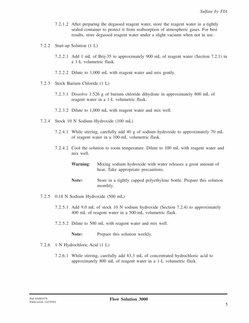
7.2.1.2 After preparing the degassed reagent water, store the reagent water in a tightlysealed container to protect it from reabsorption of atmospheric gases. For bestresults, store degassed reagent water under a slight vacuum when not in use.
7.2.2 Start-up Solution (1 L)
7.2.2.1 Add 1 mL of Brij-35 to approximately 900 mL of reagent water (Section 7.2.1) ina 1-L volumetric flask.
7.2.2.2 Dilute to 1,000 mL with reagent water and mix gently.
7.2.3 Stock Barium Chloride (1 L)
7.2.3.1 Dissolve 1.526 g of barium chloride dihydrate in approximately 800 mL ofreagent water in a 1-L volumetric flask.
7.2.3.2 Dilute to 1,000 mL with reagent water and mix well.
7.2.4 Stock 10 N Sodium Hydroxide (100 mL)
7.2.4.1 While stirring, carefully add 40 g of sodium hydroxide to approximately 70 mLof reagent water in a 100-mL volumetric flask.
7.2.4.2 Cool the solution to room temperature. Dilute to 100 mL with reagent water andmix well.
Warning: Mixing sodium hydroxide with water releases a great amount ofheat. Take appropriate precautions.
Note: Store in a tightly capped polyethylene bottle. Prepare this solutionmonthly.
7.2.5 0.18 N Sodium Hydroxide (500 mL)
7.2.5.1 Add 9.0 mL of stock 10 N sodium hydroxide (Section 7.2.4) to approximately400 mL of reagent water in a 500-mL volumetric flask.
7.2.5.2 Dilute to 500 mL with reagent water and mix well.
Note: Prepare this solution weekly.
7.2.6 1 N Hydrochloric Acid (1 L)
7.2.6.1 While stirring, carefully add 83.3 mL of concentrated hydrochloric acid toapproximately 800 mL of reagent water in a 1-L volumetric flask.

Flow Solution 30006
Part #A001978Publication 12470501
Sulfate by FIA
7.2.6.2 Cool the solution to room temperature. Dilute to 1,000 mL with reagent waterand mix well.
Warning: Mixing hydrochloric acid with water releases a great amount ofheat. Take appropriate precautions.
7.2.7 Stock Methylthymol Blue Reagent (1 L)
Note: This reagent must be prepared at least 24–48 hours prior to use.
7.2.7.1 Dissolve 0.236 g of methylthymol blue sodium salt in 50 mL of stock bariumchloride (Section 7.2.3) in a 1-L volumetric flask.
7.2.7.2 Add 142 mL of reagent water and 8 mL of 1 N hydrochloric acid (Section 7.2.6).
7.2.7.3 Dilute to 1 L with 95% ethanol.
7.2.7.4 Stir the solution vigorously on a magnetic stir plate for approximately 1 hour oruntil the solution is thoroughly degassed.
7.2.7.5 Add additional 95% ethanol to bring the solution back to a final volume of1,000 mL. Filter through a 0.45-µm filter.
Note: Store in an amber bottle at 4°C. If stored properly, this solution isstable for 1–2 weeks.
7.2.8 Working Methylthymol Blue Reagent (500 mL)
7.2.8.1 Add 2.5 mL of Brij-35 to 500 mL of stock methylthymol blue reagent(Section 7.2.7) and mix gently.
7.2.8.2 Adjust the pH of the reagent to 2.6–2.7 using 0.18 N sodium hydroxide(Section 7.2.5) or 1 N hydrochloric acid (Section 7.2.6).
Note: Prepare this solution fresh daily.
7.2.9 Buffer, pH 10.5 (1 L)
7.2.9.1 Dissolve 6.75 g of ammonium chloride in approximately 800 mL of reagentwater in a 1-L volumetric flask.
7.2.9.2 Add 57 mL of ammonium hydroxide.
7.2.9.3 Dilute to 1,000 mL with reagent water and mix well.
Note: Prepare this solution fresh monthly.

Flow Solution 30007
Part #A001978Publication 12470501
Sulfate by FIA
7.2.10 Cleaning Solution, 4% Buffered EDTA (1 L)
7.2.10.1 Dissolve 40 g of EDTA in approximately 800 mL of pH 10.5 buffer(Section 7.2.9) in a 1-L volumetric flask.
7.2.10.2 Dilute to 1,000 mL with pH 10.5 buffer and mix well.
7.2.11 Sampler Wash—Reagent Water
7.2.12 Carrier—Reagent Water
7.3 Calibrant Preparation
7.3.1 Stock Calibrant 10,000 mg/L Sulfate (1 L)
7.3.1.1 Dissolve 14.787 g of sodium sulfate in approximately 800 mL of reagent water ina 1-L volumetric flask.
7.3.1.2 Dilute to 1,000 mL with reagent water and mix well. Preserve the solution with2 drops of chloroform.
Note: Store at 4°C. If stored properly, this solution is stable for 3 months.
7.3.2 Intermediate Calibrant 1,000 mg/L Sulfate (100 mL)
7.3.2.1 Use a volumetric pipet to add 10 mL of stock calibrant (Section 7.3.1) to approxi-mately 80 mL of reagent water in a 100-mL volumetric flask.
7.3.2.2 Dilute to 100 mL with reagent water and mix well.
Note: Prepare this solution fresh daily.
7.3.3 Working Calibrants (100 mL)
7.3.3.1 Add the designated volumes of stock or intermediate calibrant (see Equation 1) tothe required number of 100-mL volumetric flasks that each contain approxi-mately 80 mL of reagent water.
7.3.3.2 Dilute each solution to the mark with reagent water and mix well.
Note: Prepare working calibrants fresh daily.

Flow Solution 30008
Part #A001978Publication 12470501
Sulfate by FIA
EQUATION 1
C1V
1 = C
2V
2
Where:C
1 = Concentration (in mg/L) of stock solution (or calibrant)
V1 = Volume (in L) of stock solution (or calibrant) to be used
C2 = Desired concentration (in mg/L) of working calibrant to be prepared
V2 = Final volume (in L) of working calibrant to be prepared
By solving this equation for the volume of stock solution to be used (V1), the following equation is
obtained:
V1 = C
2V
2
C
1
Since the desired concentration (C2), the final volume (V
2), and the concentration of the stock solution
(C1) are all known for any given calibrant concentration in a defined volume, the volume of stock
solution to be used (V1) is easily calculated.
7.3.3.3 Calibrants covering the entire range of this analysis can be prepared from thefollowing tables.
Final Vol. of Conc. of FinalConcentration Inter. Cal. Inter. Cal. Volume
(mg/L) (µL) (mg/L) (mL)2.0 200 1,000 1005.0 500 1,000 100
Final Vol. of Conc. of FinalConcentration Stock Cal. Stock Cal. Volume
(mg/L) (µL) (mg/L) (mL)40 400 10,000 10080 800 10,000 100
120 1,200 10,000 100160 1,600 10,000 100200 2,000 10,000 100

Flow Solution 30009
Part #A001978Publication 12470501
Sulfate by FIA
8.0 Sample Collection, Preservation, and Storage
8.1 Samples should be collected in plastic or glass bottles that have been thoroughly cleaned andrinsed with reagent water (Section 7.2.1).
8.2 The volume of sample collected should be sufficient to ensure that a representative sample isobtained, replicate analysis is possible, and waste disposal is minimized.
8.3 Preserve and store samples at 4°C. Sample analysis should be performed as soon as possible toeliminate loss of analyte.
8.4 The maximum holding time is 28 days from the time of collection (Reference 15.3).
9.0 Quality Control
Note: The following QC procedures are provided for reference purposes only and are not asubstitute for any QC procedures that may be required for regulatory compliance.
9.1 It is recommended that each laboratory that uses this method operate a formal quality controlprogram. The minimum requirements of such a program should consist of an initial demonstra-tion of laboratory capability and the periodic analysis of Laboratory Control Samples (LCSs) andMatrix Spike/Matrix Spike Duplicates (MS/MSDs) as a continuing check on performance. Labora-tory performance should be compared to established performance criteria to determine if theresults of the analyses meet the performance characteristics of the method.
9.2 Method Detection Limit (MDL)—To establish the ability to detect sulfate at low levels, the analystshould determine the MDL using the apparatus, reagents, and calibrants that will be used in thepractice of this method. An MDL less than or equal to the MDL listed in Section 1.2 should beachieved prior to practice of this method.
9.2.1 An MDL is calculated by analyzing a matrix spike at a concentration of two to three timesthe expected detection limit of the analyzer. Seven consecutive replicate analyses of thismatrix spike should be analyzed, and the MDL should be calculated using Equation 2.
EQUATION 2
MDL = (t) x (S)
Where:t = Student’s t value for a 99% confidence level and a standard deviation estimate with
n–1 degrees of freedom (t = 3.14 for seven replicates)S = Standard deviation of the replicate analyses
Flow Solution 300010
Part #A001978Publication 12470501
Sulfate by FIA
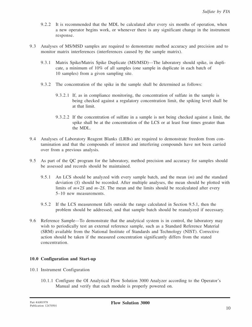
9.2.2 It is recommended that the MDL be calculated after every six months of operation, whena new operator begins work, or whenever there is any significant change in the instrumentresponse.
9.3 Analyses of MS/MSD samples are required to demonstrate method accuracy and precision and tomonitor matrix interferences (interferences caused by the sample matrix).
9.3.1 Matrix Spike/Matrix Spike Duplicate (MS/MSD)—The laboratory should spike, in dupli-cate, a minimum of 10% of all samples (one sample in duplicate in each batch of10 samples) from a given sampling site.
9.3.2 The concentration of the spike in the sample shall be determined as follows:
9.3.2.1 If, as in compliance monitoring, the concentration of sulfate in the sample isbeing checked against a regulatory concentration limit, the spiking level shall beat that limit.
9.3.2.2 If the concentration of sulfate in a sample is not being checked against a limit, thespike shall be at the concentration of the LCS or at least four times greater thanthe MDL.
9.4 Analyses of Laboratory Reagent Blanks (LRBs) are required to demonstrate freedom from con-tamination and that the compounds of interest and interfering compounds have not been carriedover from a previous analysis.
9.5 As part of the QC program for the laboratory, method precision and accuracy for samples shouldbe assessed and records should be maintained.
9.5.1 An LCS should be analyzed with every sample batch, and the mean (m) and the standarddeviation (S) should be recorded. After multiple analyses, the mean should be plotted withlimits of m+2S and m–2S. The mean and the limits should be recalculated after every5–10 new measurements.
9.5.2 If the LCS measurement falls outside the range calculated in Section 9.5.1, then theproblem should be addressed, and that sample batch should be reanalyzed if necessary.
9.6 Reference Sample—To demonstrate that the analytical system is in control, the laboratory maywish to periodically test an external reference sample, such as a Standard Reference Material(SRM) available from the National Institute of Standards and Technology (NIST). Correctiveaction should be taken if the measured concentration significantly differs from the statedconcentration.
10.0 Configuration and Start-up
10.1 Instrument Configuration
10.1.1 Configure the OI Analytical Flow Solution 3000 Analyzer according to the Operator’sManual and verify that each module is properly powered on.
Flow Solution 300011
Part #A001978Publication 12470501
Sulfate by FIA
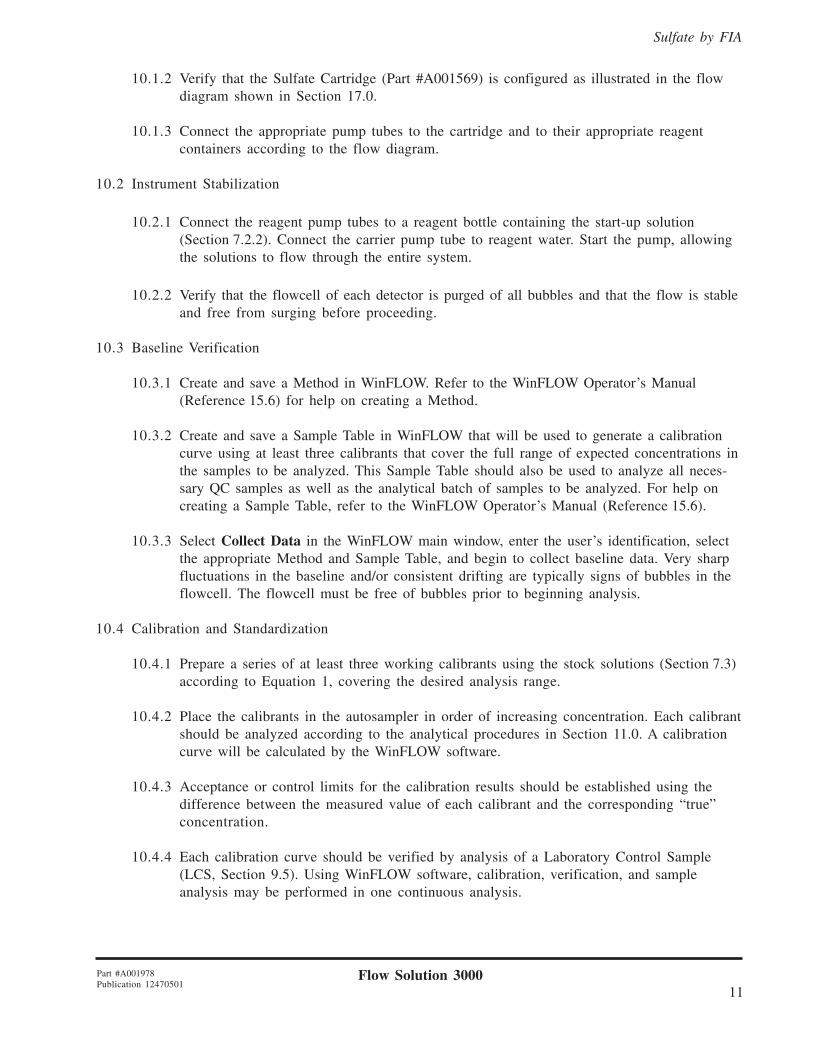
10.1.2 Verify that the Sulfate Cartridge (Part #A001569) is configured as illustrated in the flowdiagram shown in Section 17.0.
10.1.3 Connect the appropriate pump tubes to the cartridge and to their appropriate reagentcontainers according to the flow diagram.
10.2 Instrument Stabilization
10.2.1 Connect the reagent pump tubes to a reagent bottle containing the start-up solution(Section 7.2.2). Connect the carrier pump tube to reagent water. Start the pump, allowingthe solutions to flow through the entire system.
10.2.2 Verify that the flowcell of each detector is purged of all bubbles and that the flow is stableand free from surging before proceeding.
10.3 Baseline Verification
10.3.1 Create and save a Method in WinFLOW. Refer to the WinFLOW Operator’s Manual(Reference 15.6) for help on creating a Method.
10.3.2 Create and save a Sample Table in WinFLOW that will be used to generate a calibrationcurve using at least three calibrants that cover the full range of expected concentrations inthe samples to be analyzed. This Sample Table should also be used to analyze all neces-sary QC samples as well as the analytical batch of samples to be analyzed. For help oncreating a Sample Table, refer to the WinFLOW Operator’s Manual (Reference 15.6).
10.3.3 Select Collect Data in the WinFLOW main window, enter the user’s identification, selectthe appropriate Method and Sample Table, and begin to collect baseline data. Very sharpfluctuations in the baseline and/or consistent drifting are typically signs of bubbles in theflowcell. The flowcell must be free of bubbles prior to beginning analysis.
10.4 Calibration and Standardization
10.4.1 Prepare a series of at least three working calibrants using the stock solutions (Section 7.3)according to Equation 1, covering the desired analysis range.
10.4.2 Place the calibrants in the autosampler in order of increasing concentration. Each calibrantshould be analyzed according to the analytical procedures in Section 11.0. A calibrationcurve will be calculated by the WinFLOW software.
10.4.3 Acceptance or control limits for the calibration results should be established using thedifference between the measured value of each calibrant and the corresponding “true”concentration.
10.4.4 Each calibration curve should be verified by analysis of a Laboratory Control Sample(LCS, Section 9.5). Using WinFLOW software, calibration, verification, and sampleanalysis may be performed in one continuous analysis.

Flow Solution 300012
Part #A001978Publication 12470501
Sulfate by FIA
11.0 Procedure
11.1 Preparation of the Cation Exchange Column
11.1.1 Weigh 0.5 g of Bio-Rex 70 resin. Wash the resin several times with reagent water. Decantthe resin fines with the supernatant.
11.1.2 Add enough reagent water to completely cover the resin plus an additional 100 mL.Degas the resin slurry by sonicating for 15–20 minutes.
11.1.3 Remove the 1/4–28 nut and union from the column inlet. Carefully remove the frit (seeFigure 1).
11.1.4 Attach the 30-mL syringe onto the column using the union and the female Luer-Lok™
fitting. Hold the column vertically. The 0.034� PVC tubing should be parallel to thecolumn. Pour reagent water into the syringe to fill the column.
1/4–28 FemaleLuer-Lok Fitting
30-mL Syringe
1/4–28 Union
1/4–28 Union
1/4–28 Nut
1/4–28 Nut
1/4–28 Nut
Ion Exchange Column,3/32� Polypropylene
Tubing, 4� L
0.034" PVC Tubing, 6" L
Figure 1. Preparation of the Cation Exchange Column
Frit
Ferrule
1/4–28 Nut

Flow Solution 300013
Part #A001978Publication 12470501
Sulfate by FIA
11.1.5 Agitate the slurry to resuspend the resin in the reagent water. Carefully add 2 mL of theresin slurry to the syringe. Allow the resin to settle into the column. Tap the column gentlyto facilitate packing and to avoid trapping air bubbles.
11.1.6 Repeat step 11.1.5 until the column is filled with resin.
11.1.7 Remove the syringe and the 1/4–28 female Luer-Lok fitting. Carefully replace the frit.Replace the union and the 1/4–28 nut onto the column inlet.
11.2 Installation of the Cation Exchange Column
11.2.1 After all reagents have been placed on-line, the air bubbles are cleared from the system(Section 10.2), and with the pump still running, remove the jumper tubing that connectsports 4 and 8 of the cartridge (see Figure 2).
11.2.2 Remove the union connecting the 0.034" PVC tubing on the inlet and outlet of the cationexchange column. Install the column between ports 4 and 8 using the 1/4–28 nuts (seeFigure 2). Attach the nut to port 8 first to avoid introduction of air into the column.
11.2.3 Allow the baseline to restabilize before proceeding with the analysis (about 30 minutes).
� �
� �
� �
� �
�
Jumper Tubing
Cation Exchange Column
Figure 2. Installation of the Cation Exchange Column

Flow Solution 300014
Part #A001978Publication 12470501
Sulfate by FIA
11.3 Analysis
11.3.1 Begin pump flow with the start-up solution (Section 7.2.2) and reagent water as thecarrier. Verify a stable baseline (Section 10.3).
11.3.2 After the baseline has been verified according to Section 10.3, place all reagents on-lineand allow to pump at least 30 minutes and verify there are no bubbles in the flowcell.Install the cation exchange column (Section 11.2). Obtain a stable baseline at 460 nm andautozero the baseline before beginning analysis.
11.3.3 Load the sampler tray with calibrants, blanks, samples, and QC samples.
Note: The matrix of the working standards, blanks, and QC samples should match thatof the samples being analyzed.
11.3.4 Using the Method and Sample Table created for the analytical batch to be analyzed andwith the baseline verified to be stable, begin the analysis by selecting the “Fast Forward”button on the left side of the Data Analysis window in WinFLOW. This will initiate thesequential analysis of samples as defined in the Sample Table.
11.3.5 When analysis is complete, remove the cation exchange column and reinstall the jumpertubing between ports 4 and 8.
11.3.6 Pump reagent water through the system for at least 10–15 minutes. Pump cleaning solu-tion (Section 7.2.10) through the working methylthymol blue and sodium hydroxidereagent lines for at least 5 minutes. Repeat the reagent wash for 10–15 minutes. Stop thepump, release the tension on all pump tubes, and power off the system.
11.4 Operating Notes
11.4.1 Sulfate determination by the methylthymol blue method is an inherently noisy test. Usethe following suggestions to diminish the baseline noise.
11.4.1.1 Use reagent water (Section 7.2.1) to prepare all reagents, including the water forthe sampler wash.
11.4.1.2 High quality methylthymol blue is essential. Request a certificate of analysiswhen ordering this reagent since significant variation in water content occursfrom lot to lot. Use only methylthymol blue with a water content of lessthan 10%.
11.4.1.3 Use ACS reagent grade 95% ethanol.
11.4.2 The quantity of interfering cations will vary with the sample matrix. Samples with highcation concentrations may require more frequent replacement of the cation exchange resinor the installation of a longer cation exchange column.
11.3.3 Check the cation exchange capacity of the column by periodically running a mid-levelcalibrant that contains a calcium concentration similar to that of the samples being ana-lyzed. Low recovery indicates that the cation exchange capacity is exhausted.

Flow Solution 300015
Part #A001978Publication 12470501
Sulfate by FIA
11.4.4 After a large number of high level samples have been analyzed, an increase in baselinedrift may be observed. Clean the flowcell with cleaning solution (Section 7.2.10), fol-lowed by reagent water. If the baseline drift is not improved, treat the entire manifold withcleaning solution.
11.4.5 Prepare and filter the stock methylthymol blue reagent (Section 7.2.7) at least24–48 hours prior to use. Store in an amber bottle at 4°C.
11.4.6 The pH of the working methylthymol blue reagent (Section 7.2.8) must be adjusted tobetween 2.6–2.7 prior to analysis. The pH of the final reagent stream as it leaves theflowcell should be ≥12.5.
11.4.7 When installing the cation exchange column, always have the pump running. Backpressure prevents air from becoming trapped in the column. If the pump is not runningduring installation, air will enter the column when the pump is turned on.
11.4.8 After any changes are made to the manifold, allow enough time (at least 30 minutes) forthe baseline to restabilize.
11.4.9 Clean the flowcell with 1 N sodium hydroxide and 1 N hydrochloric acid to help preventbubbles from becoming trapped in the flowcell.
11.4.10If an erratic baseline is observed, replace the working methylthymol blue reagent pumptube.
12.0 Data Analysis and Calculations
12.1 The calibration curve allows for accurate quantitation of the concentration in each sample.
12.2 WinFLOW software reports the concentration of each sample relative to the calibration curve.
13.0 Method Performance
14.0 Pollution Prevention and Waste Management
14.1 It is the laboratory’s responsibility to comply with all federal, state, and local regulations govern-ing waste management, particularly the hazardous waste identification rules and land-disposalrestrictions. In addition, it is the laboratory’s responsibility to protect air, water, and land resourcesby minimizing and controlling all releases from fume hoods and bench operations. Also, compli-ance is required with any sewage discharge permits and regulations.
Range: 2.0–200 mg/LThroughput: 55 samples/hourPrecision:
40 mg/L <3% RSD160 mg/L <2% RSD
Method Detection Limit (MDL): 1.61 mg/L

Flow Solution 300016
Part #A001978Publication 12470501
Sulfate by FIA
14.2 For further information on waste management, consult Section 13.6 of Less is Better: LaboratoryChemical Management for Waste Reduction (Reference 15.2).
15.0 References
15.1 Colovos; Panesar; Perry. Linearizing the Calibration Curve in Determination of Sulfate by theMethylthymol Blue Method. Analytical Chemistry 1976, 48 (No. 12), 1693–1696.
15.2 Less is Better: Laboratory Chemical Management for Waste Reduction. Available from the Ameri-can Chemical Society, Department of Government Regulations and Science Policy, 1155 16th
Street, NW, Washington, DC, 20036.
15.3 Sample Preservation. Methods for Chemical Analysis of Water and Wastes; EPA-600/4-79-020;U.S. Environmental Protection Agency, Office of Research and Development, EnvironmentalMonitoring and Support Laboratory: Cincinnati, OH, 1984; xvii.
15.4 Sulfate (Automated Colorimetry). Methods for the Determination of Inorganic Substances inEnvironmental Samples; EPA-600/R-93/100; U.S. Environmental Protection Agency, Office ofResearch and Development, Environmental Monitoring and Support Laboratory: Cincinnati, OH,1984; Method 375.2.
15.5 Sulfate. Standard Methods for the Examination of Water and Wastewater, 20th ed.; AmericanPublic Health Association: Washington, D.C., 1998; Method 4500-Sulfate.
15.6 WinFLOW Software and Operator’s Manual (Part #A002877). Available from OI Analytical, P.O.Box 9010, College Station, TX, 77842-9010.
16.0 Glossary of Definitions and Purposes
The definitions and purposes are specific to this method but have been conformed to common usage asmuch as possible.
16.1 Units of weights and measures and their abbreviations
16.1.1 Symbols
°C degrees Celsius% percent± plus or minus≥ greater than or equal to≤ less than or equal to
16.1.2 Alphabetical characters
g gramL litermg milligram

Flow Solution 300017
Part #A001978Publication 12470501
Sulfate by FIA
mg/L milligram per literµg microgramµg/L microgram per litermL milliliterppm parts per millionppb parts per billionM molar solutionN normal solution
16.2 Definitions
16.2.1 Laboratory Control Sample (LCS)—An aliquot of LRB to which a quantity of the analyteof interest is added in the laboratory. The LCS is analyzed like a sample. Its purpose is todetermine whether the methodology is in control and whether the laboratory is capable ofmaking accurate and precise measurements.
16.2.2 Laboratory Reagent Blank (LRB)—An aliquot of reagent water and other blank matrixthat is treated like a sample, including exposure to all glassware, equipment, and reagentsthat are used with other samples. The LRB is used to determine if the method analyte orother interferences are present in the laboratory environment, reagents, or apparatus.
16.2.3 Matrix Spike/Matrix Spike Duplicate (MS/MSD)—An aliquot of an environmental sampleto which a quantity of the method analyte is added in the laboratory. The MS/MSD isanalyzed like a sample. Its purpose is to determine whether the sample matrix contributesbias to the analytical results. The background concentration of the analyte in the samplematrix must be determined in a separate aliquot, and the measured values in the MS/MSDmust be corrected for the background concentration.
16.2.4 Method Detection Limit (MDL)—The minimum concentration of a substance that can bemeasured and reported with 99% confidence that the analyte concentration is greater thanzero.

Flow Solution 300018
Part #A001978Publication 12470501
Sulfate by FIA
Figu
re 3
. D
etai
led
Flow
Dia
gram
for
Sul
fate
by
FIA
on
a Fl
ow S
olut
ion
3000
, Car
trid
ge P
art #
A00
1569
17.0 Figures
��
��
��
�
���
����
��
��
���
�
���
���
��
����
��
����
!"
#!
$%
��
!&%
��
'%
&'
�
���
���
!���
���
(��
�(
)�
��
��*
�
+� ,&
�%
#!
&�
-(
�*
��
��
�%
��
-��
-(
.-�
.
&*
�
*
%�
��
��/��
�.
0/��
��/�
�*�
(��
�&
1 + � 2
3 � 4
5
-(��
�-*
�#
%(
-$*
&)
#�6
���
���
��
.��
.�
�� ��
3� ��
� ��
&��
��/
#��
����
���7
!�
��8
�+ 9
-8)
8
$��
:��
��
���
���
&���
�0��
���
;���
���
����
���
�����
�:
����
8
!��
��
�;��
���
����
���;��
7!
���
8�+
9-8)
8
-���
����
!���
������
����
!��
�;�
/!��
�
��
��0
!���
-���
����
��;��
7!
���
8�+
9-8)
8
60�
���
&���7
��<���
=�
8�3�
9-8)
8
"���
�
���
����
�����
��
����
��

Flow Solution 300019
Part #A001978Publication 12470501
Sulfate by FIA
P.O. Box 9010College Station, Texas 77842-9010
Tel: (979) 690-1711 · FAX: (979) 690-0440
Results were obtained under optimal operating conditions. Actualresults may vary depending on sample introduction, cleanliness ofsample containers, reagent purity, operator skill, and maintenanceof instruments.
Bio-Rex is a registered trademark of Bio-Rad Laboratories.Brij is a registered trademark of ICI Americas.Luer-Lok is a trademark of Becton Dickenson.Teflon is a registered trademark of E.I. DuPont de Nemours.Flow Solution is a registered trademark of OI Analytical.WinFLOW is a trademark of OI Analytical.
Copyright 2001, OI Analytical, College Station, TX 77842.