summary of working group a: injector design ivan bazarov, xiangyun chang, massimo ferrario, bob...
Post on 21-Dec-2015
218 views
TRANSCRIPT

Summary of Working Group A: Injector Design
Ivan Bazarov, Xiangyun Chang, Massimo Ferrario, Bob Garnett, Dmitry Kayran, Sergey Kurennoy, John Lewellen,
Ji Qiang, Dave Sutter, Xijie Wang

Outline of Discussion Topics
• Injector design theory, new concept and methodology
• Computational requirements and challenges in the injector design
• Current available computation tools
• Simulation codes verification and validiation
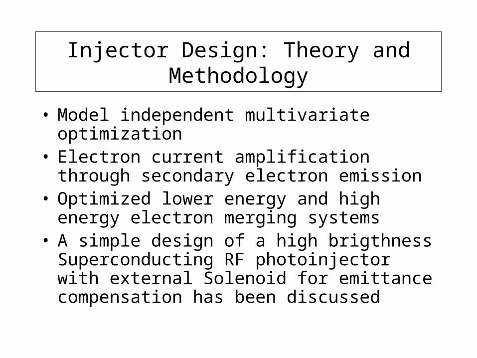
Injector Design: Theory and Methodology
• Model independent multivariate optimization• Electron current amplification through secondary
electron emission• Optimized lower energy and high energy electron
merging systems• A simple design of a high brigthness
Superconducting RF photoinjector with external Solenoid for emittance compensation has been discussed
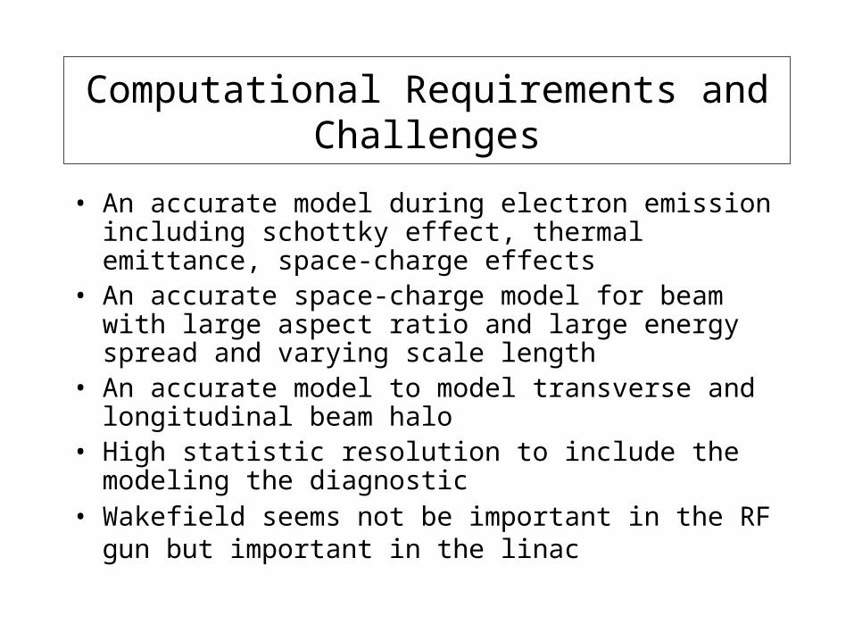
Computational Requirements and Challenges
• An accurate model during electron emission including schottky effect, thermal emittance, space-charge effects
• An accurate space-charge model for beam with large aspect ratio and large energy spread and varying scale length
• An accurate model to model transverse and longitudinal beam halo
• High statistic resolution to include the modeling the diagnostic
• Wakefield seems not be important in the RF gun but important in the linac
Current Available Computational Tools
• ASTRA:
• GPT:
• IMPACT-T:
• PARMELA:
• HOMDYN:
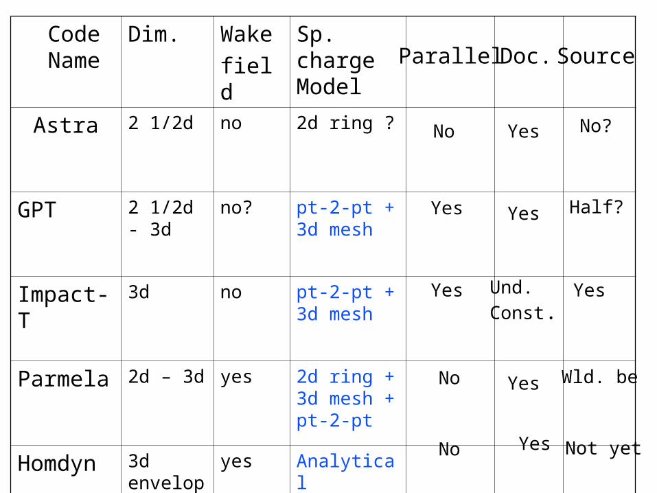
Code Name
Dim. Wake
field
Sp. charge Model
Astra 2 1/2d no 2d ring ?
GPT 2 1/2d - 3d
no? pt-2-pt + 3d mesh
Impact-T 3d no pt-2-pt + 3d mesh
Parmela 2d – 3d yes 2d ring + 3d mesh + pt-2-pt
Homdyn 3d envelope
yes Analytical
Parallel Doc. Source
No
Yes
Yes
No
No
Yes
Yes
Und.
Const.
Yes
No?
Half?
Yes
Wld. be
Not yetYes
Simulation Codes Verification and Validiation
• Code benchmark should be done for a number of cases with parameters which account for different operation regime, e.g. low emittance, high charge, large aspect ratio beam, large energy spread beam, beam with initial halo
• Dedicated experiments are needed for testing the simulation codes, e.g. SPARC, GTF, PITZ, ……
PARMELA
Bob GarnettLos Alamos National Laboratory
Workshop on High Average Power & High Brightness BeamsUCLA
November 8-10, 2004
Outline
• Present Status of PARMELA
• PARMELA Code Description
- Main Features
- Additional Features
Space Charge
Wakefields and BBU
CSR
• Validation, Benchmarking, & Limitations
• Areas of Improvement / Collaborations?
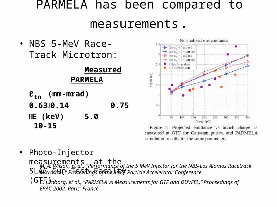
PARMELA has been compared to measurements.
• NBS 5-MeV Race-Track Microtron:
Measured PARMELA
tn (mm-mrad) 0.630.14
0.75
E (keV) 5.0 10-15
• Photo-Injector measurements at the SLAC Gun Test Facilty (GTF).
M. A. Wilson, et al., “Performance of the 5 MeV Injector for the NBS-Los Alamos Racetrack Microtron,” Proceedings of the 1987 Particle Accelerator Conference.
C. Limborg, et al., “PARMELA vs Measurements for GTF and DUVFEL,” Proceedings of EPAC 2002, Paris, France.
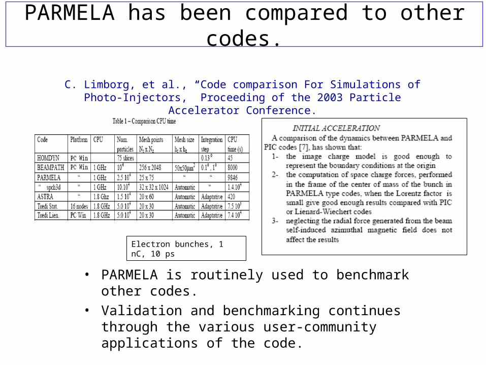
PARMELA has been compared to other codes.
• PARMELA is routinely used to benchmark other codes.
• Validation and benchmarking continues through the various user-community applications of the code.
C. Limborg, et al., “Code comparison For Simulations of Photo-Injectors,” Proceeding of the 2003 Particle Accelerator Conference.
Electron bunches, 1 nC, 10 ps
PARMELA has been compared to other codes (cont.)
• PARMELA accuracy in question for low-energies near the cathode for high-brightness regime.
• Did numerical comparison of PARMELA results with ARGUS PIC simulations.
• Found good agreement for bunch charge < 7 nC and pulse lengths < 50 psec.
• May need codes like ARGUS or MAFIA (pushing particles) if in higher space charge regimes.
Claudio Parazzoli, et al. “Boeing Design Codes”Navy MWFEL Design Code Review, March 24-25, 2004
Naval Postgraduate School, Monterey, CA
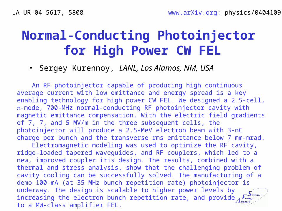
Normal-Conducting Photoinjector for High Power CW FEL
• Sergey Kurennoy, LANL, Los Alamos, NM, USA
An RF photoinjector capable of producing high continuous average current with low emittance and energy spread is a key enabling technology for high power CW FEL. We designed a 2.5-cell, -mode, 700-MHz normal-conducting RF photoinjector cavity with magnetic emittance compensation. With the electric field gradients of 7, 7, and 5 MV/m in the three subsequent cells, the photoinjector will produce a 2.5-MeV electron beam with 3-nC charge per bunch and the transverse rms emittance below 7 mm-mrad. Electromagnetic modeling was used to optimize the RF cavity, ridge-loaded tapered waveguides, and RF couplers, which led to a new, improved coupler iris design. The results, combined with a thermal and stress analysis, show that the challenging problem of cavity cooling can be successfully solved. The manufacturing of a demo 100-mA (at 35 MHz bunch repetition rate) photoinjector is underway. The design is scalable to higher power levels by increasing the electron bunch repetition rate, and provides a path to a MW-class amplifier FEL.
LA-UR-04-5617,-5808 www.arXiv.org: physics/0404109
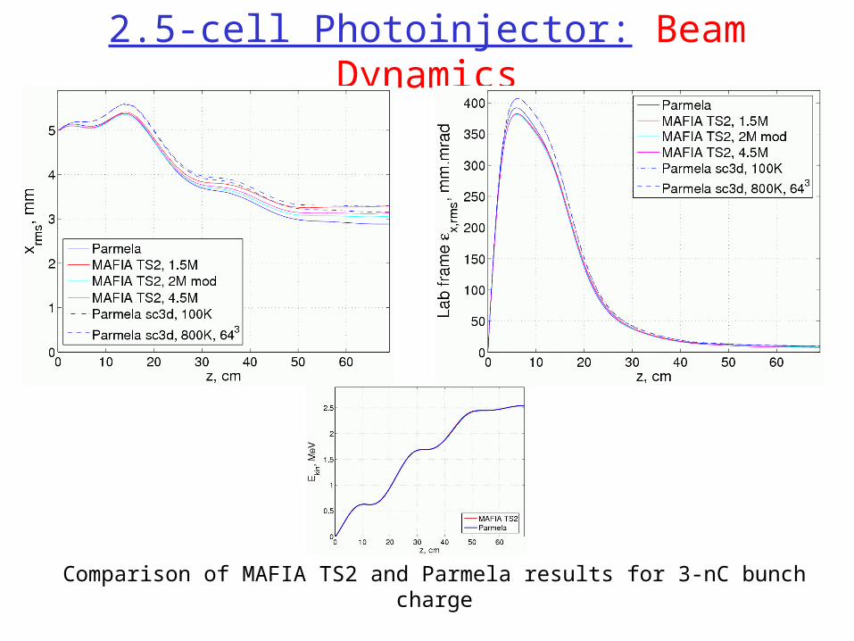
2.5-cell Photoinjector: Beam Dynamics
Comparison of MAFIA TS2 and Parmela results for 3-nC bunch charge
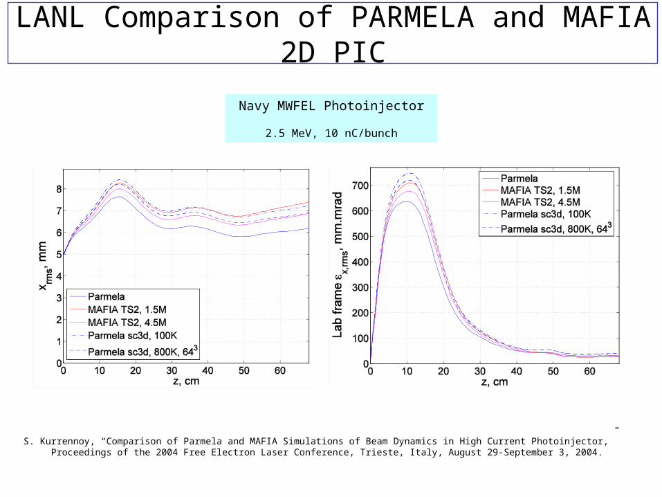
LANL Comparison of PARMELA and MAFIA 2D PIC
S. Kurrennoy, “Comparison of Parmela and MAFIA Simulations of Beam Dynamics in High Current Photoinjector,” Proceedings of the 2004 Free Electron Laser Conference, Trieste, Italy, August 29-September 3, 2004.
Navy MWFEL Photoinjector
2.5 MeV, 10 nC/bunch
IMPACT-T - A 3D Parallel Beam Dynamics Code for Modeling High Brightness Beams in Photo-Injectors
Ji Qiang Lawrence Berkeley National Laboratory
Work performed under the auspices of theDOE Grand Challenge in Computational Accelerator Physics,
Advanced Computing for 21st Century Accelerator Science and Technology Project using resources at the
Advanced Computing Laboratory and theNational Energy Research Scientific Computing Center
What is new in the IMPACT-T code?
• Integrated Green method to accurately compute the space-charge forces for a beam with large aspect ratio
• Shifted Green method to efficiently compute the space-charge forces from the image charge
• Multiple slices/bins to handle the beam with large energy spread
• Parallel implementation on high performance computer to allow multiple million, high resolution simulation

Green Function Solution of Poisson’s Equation (cont’d)
€
φF(r) = Gs(r,r')ρ(r')dr'∫Gs(r,r') = G(r + rs,r')
€
φc(ri) = h Gc(rii '=1
2N
∑ − ri' )ρc(ri' )
€
φ(ri) = φc(ri) for i = 1, N
Hockney’s Algorithm:- scales as (2N)3log(2N)- Ref: Hockney and Easwood, Computer Simulation using Particles, McGraw-Hill Book Company, New York, 1985.
Shifted Green function Algorithm:
e-
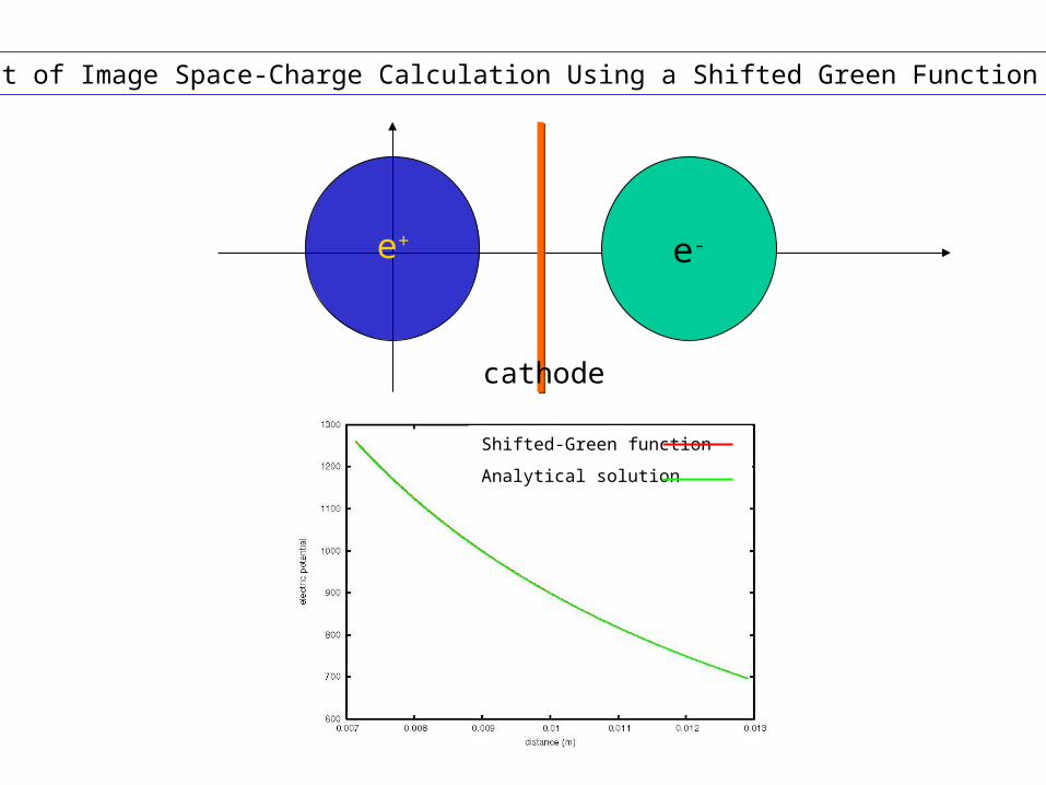
Test of Image Space-Charge Calculation Using a Shifted Green Function Method
e+
cathode
Shifted-Green function
Analytical solution
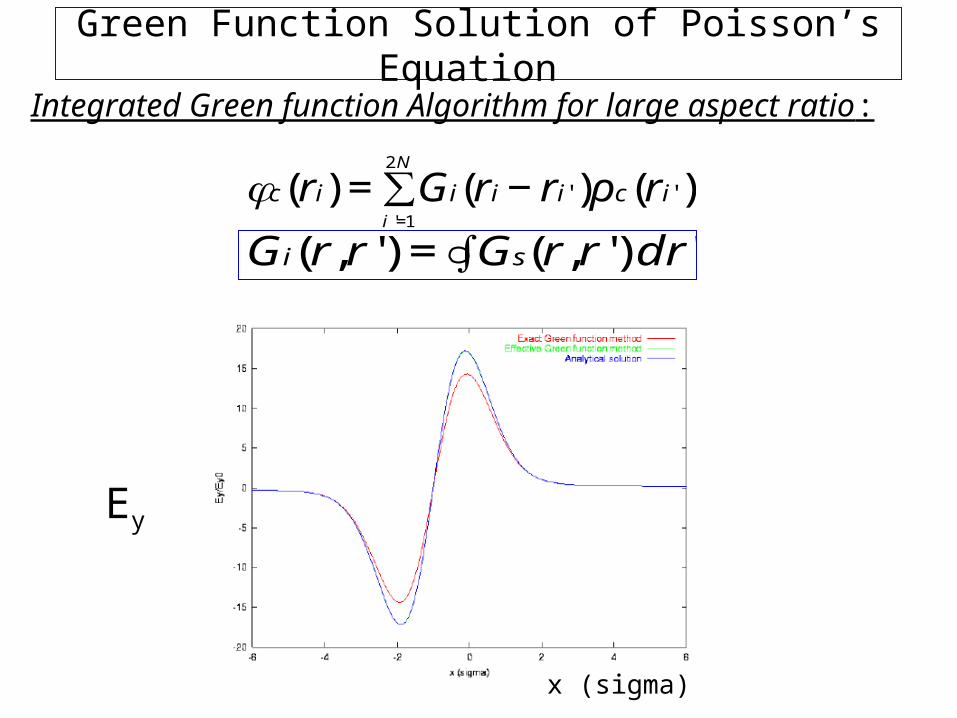
Green Function Solution of Poisson’s Equation
€
φc(ri) = Gi(rii '=1
2N
∑ − ri' )ρc(ri' )
€
Gi(r,r') = Gs(r,r') dr'∫
Integrated Green function Algorithm for large aspect ratio:
x (sigma)
Ey
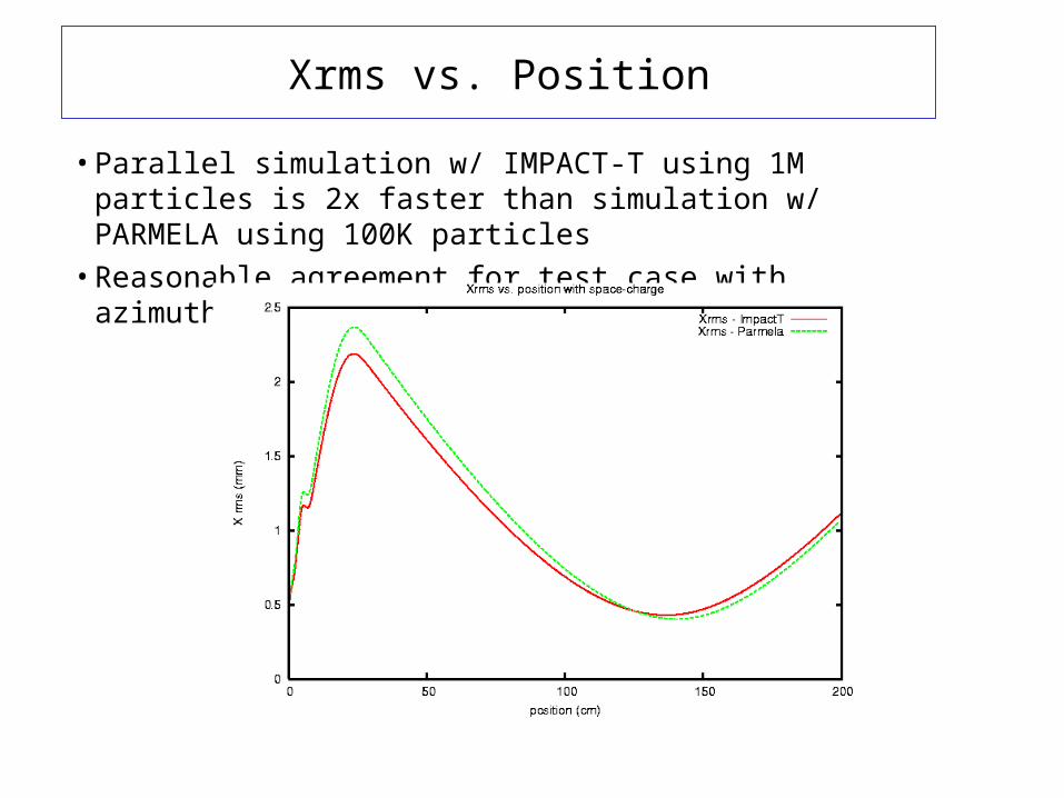
Xrms vs. Position
• Parallel simulation w/ IMPACT-T using 1M particles is 2x faster than simulation w/ PARMELA using 100K particles
• Reasonable agreement for test case with azimuthal symmetry
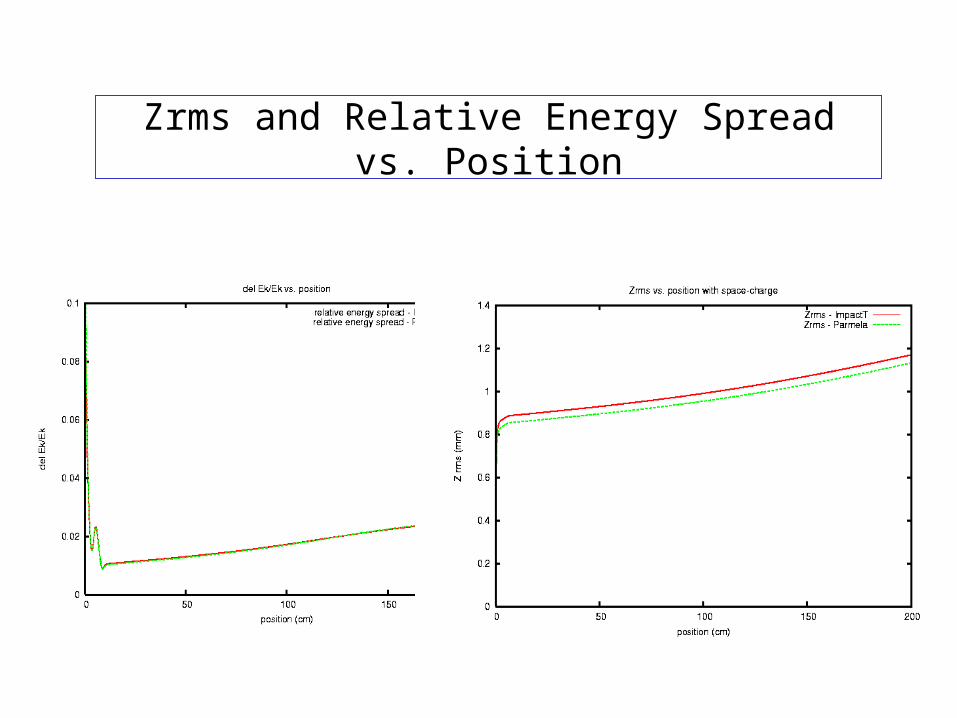
Zrms and Relative Energy Spread vs. Position
HOMDYN(Higher Order Modes DYNamics)
Acknowledgements: J. B. Rosensweig, L. Serafini,
J.P. Carneiro, J. Clendenin, H. Edwards, V. Fusco, L. Giannessi, M. Migliorati, A. Mosnier, D.T. Palmer, L. Palumbo, Ph. Piot, M. Quattromini ,T. Ronsivalle, J. Sekutowicz, F. Tazzioli.
QuickTime™ and aTIFF (Uncompressed) decompressorare needed to see this picture.
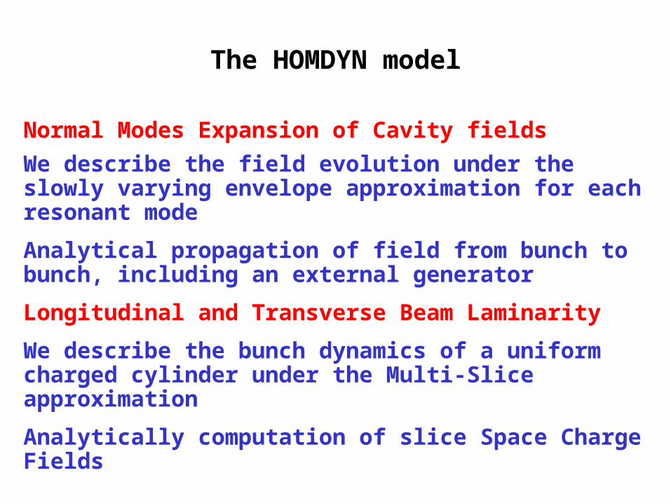
The HOMDYN model
Normal Modes Expansion of Cavity fields
We describe the field evolution under the slowly varying envelope approximation for each resonant mode
Analytical propagation of field from bunch to bunch, including an external generator
Longitudinal and Transverse Beam Laminarity
We describe the bunch dynamics of a uniform charged cylinder under the Multi-Slice approximation
Analytically computation of slice Space Charge Fields
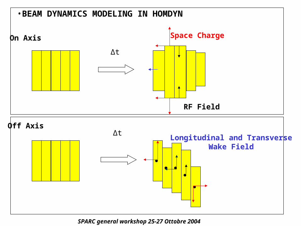
•BEAM DYNAMICS MODELING IN HOMDYN
Δt
Δt
Space Charge
Longitudinal and TransverseWake Field
On Axis
Off Axis
RF Field
SPARC general workshop 25-27 Ottobre 2004
L(t)Rs(t)
t
t
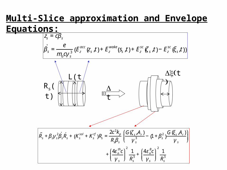
Multi-Slice approximation and Envelope Equations:
˙ ̇ R s +βsγs2 ˙ β s ˙ R s + Ks
sol +Ksrf
( )Rs =2c2kp
Rsβs
G(ζs,Ar)γs
3 − 1+βs2
( )G(ξs,Ar)
γs
⎛
⎝ ⎜
⎞
⎠ ⎟
+4εn
thcγs
⎛
⎝ ⎜
⎞
⎠ ⎟
21Rs
3 +4εn
Bcγs
⎛
⎝ ⎜
⎞
⎠ ⎟
21Rs
3
˙ z s =cβs
˙ β s =e
mocγs3 Ez
acc zs,t( )+Ezwake ss,t( )+Ez
sc ζs,t( )−Ezsc ξs,t( )( )
0
0.5
1
1.5
2
2.5
3
3.5
0 100 200 300 400 500 600 700 800
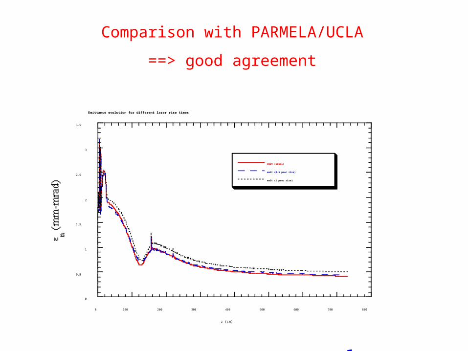
Emittance evolution for different laser rise times
emit (ideal)
emit (0.5 psec rise)
emit (1 psec rise)
n
(mm-mrad)
z (cm)
Comparison with PARMELA/UCLA
==> good agreement
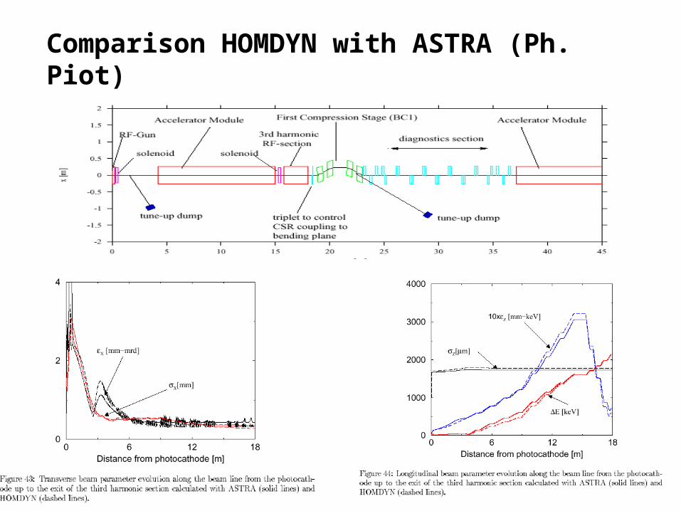
Comparison HOMDYN with ASTRA (Ph. Piot)
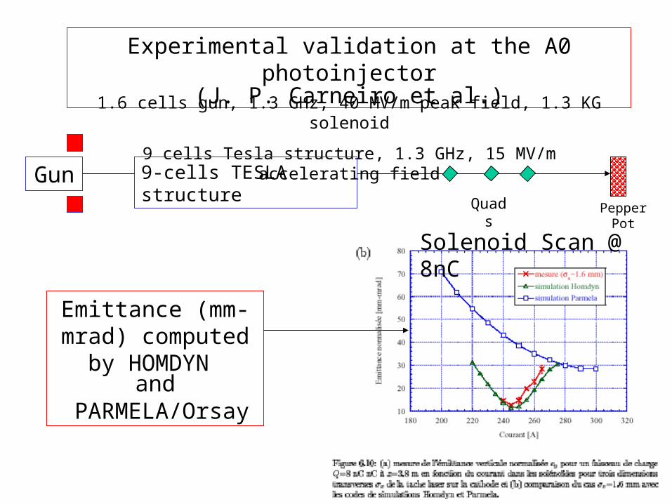
Experimental validation at the A0 photoinjector(J. P. Carneiro et al.)
1.6 cells gun, 1.3 GHz, 40 MV/m peak field, 1.3 KG solenoid
9 cells Tesla structure, 1.3 GHz, 15 MV/m accelerating field
9-cells TESLA structureGunPepperPo
t
Quads
Solenoid Scan @ 8nC
Emittance (mm-mrad) computed by HOMDYN
and PARMELA/Orsay
Brookhaven Science AssociatesU.S. Department of Energy
A Few Comments on the Photoinjector Performance
X.J. WangNational Synchrotron Light SourceBrookhaven National Laboratory
Upton, NY 11973, USA
Presented at the UCLA High-Power Brightness Beams WorkshopNov.9, 2004
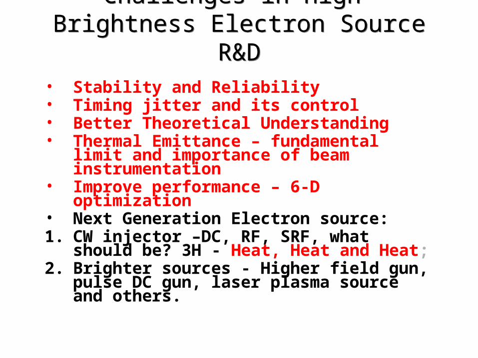
Challenges in High-Brightness Electron Source R&D
Challenges in High-Brightness Electron Source R&D
• Stability and Reliability• Timing jitter and its control• Better Theoretical Understanding• Thermal Emittance – fundamental limit and
importance of beam instrumentation• Improve performance – 6-D optimization• Next Generation Electron source:1. CW injector –DC, RF, SRF, what should be?
3H - Heat, Heat and Heat;2. Brighter sources - Higher field gun, pulse
DC gun, laser plasma source and others.
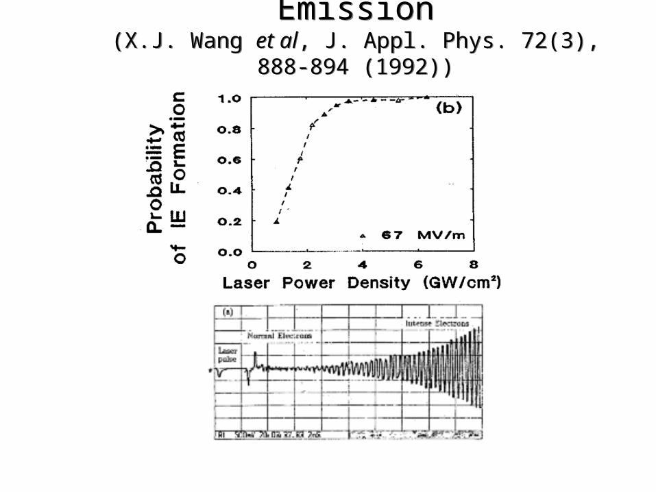
Laser-Induced Explosive Emission(X.J. Wang et al, J. Appl. Phys. 72(3), 888-894 (1992))Laser-Induced Explosive Emission
(X.J. Wang et al, J. Appl. Phys. 72(3), 888-894 (1992))
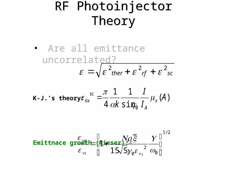
RF Photoinjector TheoryRF Photoinjector Theory
• Are all emittance uncorrelated?
K-J.’s theory:
Emittnace growth (Rieser):
scrfther222 ++=
2/1
02
0515
~1
⎥⎥⎦
⎤
⎢⎢⎣
⎡+=
wUxNr
in
c
ni
nf
γ
)(sin
11
4 0
AI
I
k xA
scnx μ
φα =
Linac 2000)