summary: processing options - university of california ...matclass/101/pdffiles/lecture_16.pdf ·...
TRANSCRIPT

Summary: Processing Options
Austenite (γ)
Bainite (α + Fe3C plates/needles)
Pearlite (α + Fe3C layers + a
proeutectoid phase)
Martensite (BCT phase diffusionless
transformation)
Tempered Martensite (α + very fine
Fe3C particles)
slow cool
moderate cool
rapid quench
reheat
Str
en
gth
Du
cti
lity
Martensite T Martensite
bainite fine pearlite
coarse pearlite spheroidite
General Trends
Adapted from Fig. 10.27, Callister 6e.

Chapter 11: Metal AlloysApplications and Processing
ISSUES TO ADDRESS...
• How are metal alloys classified and how are they used?
• What are some of the common fabrication techniques?
• How do properties vary throughout a piece of materialthat has been quenched, for example?
• How can properties be modified by post heat treatment?

Taxonomy of Metals
Adapted from Fig. 9.21,Callister 6e. (Fig. 9.21 adapted from Binary Alloy Phase Diagrams, 2nd ed.,Vol. 1, T.B. Massalski (Ed.-in-Chief), ASM International, Materials Park, OH, 1990.)
Adapted from Fig. 11.1, Callister 6e.
Fe3C
cementite
Metal Alloys
Steels
Ferrous Nonferrous
Cast Irons Cu Al Mg Ti<1.4wt%C 3-4.5wt%C
1600
1400
1200
1000
800
600
4000 1 2 3 4 5 6 6.7
L
γaustenite
γ+L
γ+Fe3Cα
ferriteα+Fe3C
α+γ
L+Fe3C
δ
(Fe) Co, wt% C
Eutectic:
Eutectoid:0.77
4.30
727°C
1148°C
T(°C)
Steels<1.4wt%C
Cast Irons3-4.5wt%C
microstructure: ferrite, graphite cementite

Steels
Low Alloy High Alloy
low carbon <0.25wt%C
med carbon 0.25-0.6wt%C
high carbon 0.6-1.4wt%C
Uses auto struc. sheet
bridges towers press. vessels
crank shafts bolts hammers blades
pistons gears wear applic.
wear applic.
drills saws dies
high T applic. turbines furnaces V. corros. resistant
Example 1010 4310 1040 4340 1095 4190 304
Additions noneCr,V Ni, Mo
noneCr, Ni Mo
noneCr, V, Mo, W
Cr, Ni, Mo
plain HSLA plainheat
treatableplain tool
austentitic stainless
Name
Hardenability 0 + + ++ ++ +++ 0TS - 0 + ++ + ++ 0EL + + 0 - - -- ++
increasing strength, cost, decreasing ductilityBased on data provided in Tables 11.1(b), 11.2(b), 11.3, and 11.4, Callister 6e.

Basic Ideas in Alloying Steels:1. Phase Partitioning at Austenite/Pearlite Interface
Carbide FormersV, Ti, Nb
Ferrite Formers (solid solution)Ni, Si, Mn
Paritioning at the Austenite/Pearlite InterfaceSlows transformationAllows Bainite or Martensite to form on cooling

Basic Ideas in Alloying Steels:2. Alloying to Control the Eutectoid Transformation
AlloyingControl ‘Nose’ in TTT DiagramControl Eutectoid Temperature and C Composition
Cr: added (~8 – 12wt %) to make steel ‘stainless’Ni: High concentrations to stabilize austenite – austenitic steels

Hardenability of Steels
• Ability to form martensite• Jominy end quench test to measure hardenability.
• Hardness versus distance from the quenched end.
24°C water
specimen (heated to γ phase field)
flat ground
4”
1”
Ha
rdn
ess
, HR
C
Distance from quenched end
Adapted from Fig. 11.10, Callister 6e. (Fig. 11.10 adapted from A.G. Guy, Essentials of Materials Science, McGraw-Hill Book Company, New York, 1978.)
Adapted from Fig. 11.11, Callister 6e.

Why Hardness Changes with Position
• The cooling rate varies with position.
Adapted from Fig. 11.12, Callister 6e. (Fig. 11.12 adapted from H. Boyer (Ed.) Atlas of Isothermal Transformation and Cooling Transformation Diagrams, American Society for Metals, 1977, p. 376.)
distance from quenched end (in)Ha
rdn
ess
, HR
C
20
40
60
0 1 2 3
600
400
200A → M
A → P
Martensite
Martensite + Pearlite
Fine Pearlite
Pearlite
0.1 1 10 100 1000
T(°C)
M(start)
Time (s)
0
0%100%
M(finish)

Hardenability vs. Alloy Content
• Jominy end quenchresults, C = 0.4wt%C
• "Alloy Steels"(4140, 4340, 5140, 8640)--contain Ni, Cr, Mo
(0.2 to 2wt%)--these elements shift
the "nose".--martensite is easier
to form.
Adapted from Fig. 11.13, Callister 6e. (Fig. 11.13 adapted from figure furnished courtesy Republic Steel Corporation.)
T(°C)
10-1 10 103 1050
200
400
600
800
Time (s)
M(start)M(90%)
TE
A Bshift from A to B due to alloying
Cooling rate (°C/s)
Ha
rdn
ess
, HR
C
20
40
60
100 20 30 40 50Distance from quenched end (mm)
210100 3
4140
8640
5140
1040
50
80
100
%M4340

Quenching Medium and Geometry
• Effect of quenching medium:
Mediumairoil
water
Hardnesssmall
moderatelarge
Severity of Quenchsmall
moderatelarge
• Effect of geometry:When surface-to-volume ratio increases:
--cooling rate increases--hardness increases
Positioncenter
surface
Cooling ratesmalllarge
Hardnesssmalllarge
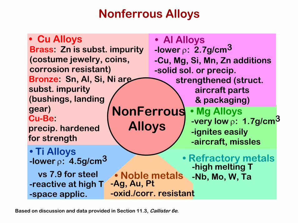
Nonferrous Alloys
NonFerrous Alloys
• Cu AlloysBrass: Zn is subst. impurity (costume jewelry, coins, corrosion resistant)Bronze: Sn, Al, Si, Ni are subst. impurity (bushings, landing gear)Cu-Be: precip. hardened for strength
• Al Alloys-lower ρ: 2.7g/cm3 -Cu, Mg, Si, Mn, Zn additions -solid sol. or precip. strengthened (struct.
aircraft parts & packaging)
• Mg Alloys-very low ρ: 1.7g/cm3 -ignites easily -aircraft, missles
• Refractory metals-high melting T -Nb, Mo, W, Ta• Noble metals
-Ag, Au, Pt -oxid./corr. resistant
• Ti Alloys-lower ρ: 4.5g/cm3
vs 7.9 for steel -reactive at high T -space applic.
Based on discussion and data provided in Section 11.3, Callister 6e.

Metal Fabrication Methods (1)
CASTING JOININGFORMING
Ao Ad
force
dieblank
force
• Forging(wrenches, crankshafts)
• Rolling(I-beams, rails)
• Extrusion(rods, tubing)
Adapted from Fig. 11.7, Callister 6e.
ram billet
container
containerforce
die holder
die
Ao
Adextrusion
roll
AoAd
roll
• Drawing(rods, wire, tubing)
often atelev. T
tensile force
AoAddie
die

Forming Temperature
• Hot working--recrystallization--less energy to deform--oxidation: poor finish--lower strength
• Cold working--recrystallization--less energy to deform--oxidation: poor finish--lower strength
• Cold worked microstructures--generally are very anisotropic!--Forged --Fracture resistant!
Reprinted w/ permission from R.W. Hertzberg, "Deformation and Fracture Mechanics of Engineering Materials", (4th ed.), John Wiley and Sons, Inc., 1996. (a) Fig. 10.5, p. 410 (micrograph courtesy of G. Vander Voort, Car Tech Corp.); (b) Fig. 10.6(b), p. 411 (Orig. source: J.F. Peck and D.A. Thomas, Trans. Metall. Soc. AIME, 1961, p. 1240); (c) Fig. 10.10, p. 415 (Orig. source: A.J. McEvily, Jr.and R.H. Bush, Trans. ASM 55, 1962, p. 654.)
(a) (b) (c)
--Swaged

Metal Fabrication Methods (2)
plasterdie formedaround waxprototype
FORMING JOININGCASTING• Sand Casting
(large parts, e.g.,auto engine blocks)
Sand Sand
molten metal
• Investment Casting(low volume, complex shapese.g., jewelry, turbine blades)
wax
• Die Casting(high volume, low T alloys)
• Continuous Casting(simple slab shapes)
molten
solidified

Metal Fabrication Methods (3)
CASTINGFORMING JOINING• Powder Processing
(materials w/low ductility)
pressure
heat
point contact at low T
densification by diffusion at higher T
area contact
densify
• Welding(when one large part isimpractical)
• Heat affected zone:(region in which themicrostructure has beenchanged).
Adapted from Fig. 11.8, Callister 6e.(Fig. 11.8 from Iron Castings Handbook, C.F. Walton and T.J. Opar (Ed.), 1981.)
piece 1 piece 2
fused base metal
filler metal (melted)base metal (melted)
unaffectedunaffectedheat affected zone

Thermal Processing of Metals
Annealing: Heat to Tanneal, then cool slowly.
Types of Annealing
• Process Anneal: Negate effect of cold working by (recovery/ recrystallization)
• Stress Relief: Reduce stress caused by:
-plastic deformation -nonuniform cooling -phase transform.
• Normalize (steels): Deform steel with large grains, then normalize to make grains small.
• Full Anneal (steels): Make soft steels for good forming by heating to get γ, then cool in furnace to get coarse P.
• Spheroidize (steels): Make very soft steels for good machining. Heat just below TE & hold for
15-25h.
Based on discussion in Section 11.7, Callister 6e.

Precipitation Hardening
• Particles impede dislocations.• Ex: Al-Cu system• Procedure:
--Pt A: solution heat treat(get α solid solution)
--Pt B: quench to room temp.--Pt C: reheat to nucleate
small θ crystals withinα crystals.
• Other precipitationsystems:• Cu-Be• Cu-Sn• Mg-Al
Pt A (sol’n heat treat)
Pt B
Pt C (precipitate θ)
Temp.
Time
Adapted from Fig. 11.22, Callister 6e. (Fig. 11.22 adapted from J.L. Murray, International Metals Review 30, p.5, 1985.)
Adapted from Fig. 11.20, Callister 6e.
300
400
500
600
700
0 10 20 30 40 50wt%Cu(Al)
Lα+Lα
α+θθ
θ+L
T(°C)
A
B
C
composition range needed for precipitation hardening
CuAl2

Precipitate Effect on TS, %El
• 2014 Al Alloy:
• TS peaks withprecipitation time.
• Increasing T acceleratesprocess.
• %EL reaches minimumwith precipitation time.
precipitation heat treat time (h)
ten
sile
str
en
gth
(M
Pa
)
300
400
500
2001min 1h 1day 1mo 1yr
204°C
149°C
non-
equi
l. so
lid s
olut
ion
man
y sm
all
prec
ipita
tes
“ag
ed”
fe
wer
larg
e
pre
cipi
tate
s
“ove
rage
d”%
EL
(2
in s
am
ple
)10
20
30
0 1min 1h 1day 1mo 1yr
204°C 149°C
precipitation heat treat time (h)
Adapted from Fig. 11.25 (a) and (b), Callister 6e. (Fig. 11.25 adapted from Metals Handbook: Properties and Selection: Nonferrous Alloys and Pure Metals, Vol. 2, 9th ed., H. Baker (Managing Ed.), American Society for Metals, 1979. p. 41.)

Summary
• Steels: increase TS, Hardness (and cost) by adding--C (low alloy steels)--Cr, V, Ni, Mo, W (high alloy steels)--ductility usually decreases w/additions.
• Non-ferrous:--Cu, Al, Ti, Mg, Refractory, and noble metals.
• Fabrication techniques:--forming, casting, joining.
• Hardenability--increases with alloy content.
• Precipitation hardening--effective means to increase strength in
Al, Cu, and Mg alloys.

Chapter 8: Mechanical Failure
ISSUES TO ADDRESS...• How do flaws in a material initiate failure?• How is fracture resistance quantified; how do different
material classes compare?• How do we estimate the stress to fracture?• How do loading rate, loading history, and temperature
affect the failure stress?
Ship-cyclic loadingfrom waves.
Computer chip-cyclicthermal loading.
Hip implant-cyclicloading from walking.
Adapted from Fig. 8.0, Callister 6e.(Fig. 8.0 is by Neil Boenzi, The New York Times.)
Adapted from Fig. 18.11W(b), Callister 6e. (Fig. 18.11W(b) is courtesy of National Semiconductor Corporation.)
Adapted from Fig. 17.19(b), Callister 6e.

Ductile vs. Brittle Failure
Highly Ductile Moderately Ductile Brittle
Ductile:Warning before
fracture
Brittle:Little
warning

Example: Pipe Failure
• Ductile failure:--one piece--large deformation
• Brittle failure:--many pieces--small deformation
Figures from V.J. Colangelo and F.A. Heiser, Analysis of Metallurgical Failures (2nd ed.), Fig. 4.1(a) and (b), p. 66 John Wiley and Sons, Inc., 1987. Used with permission.
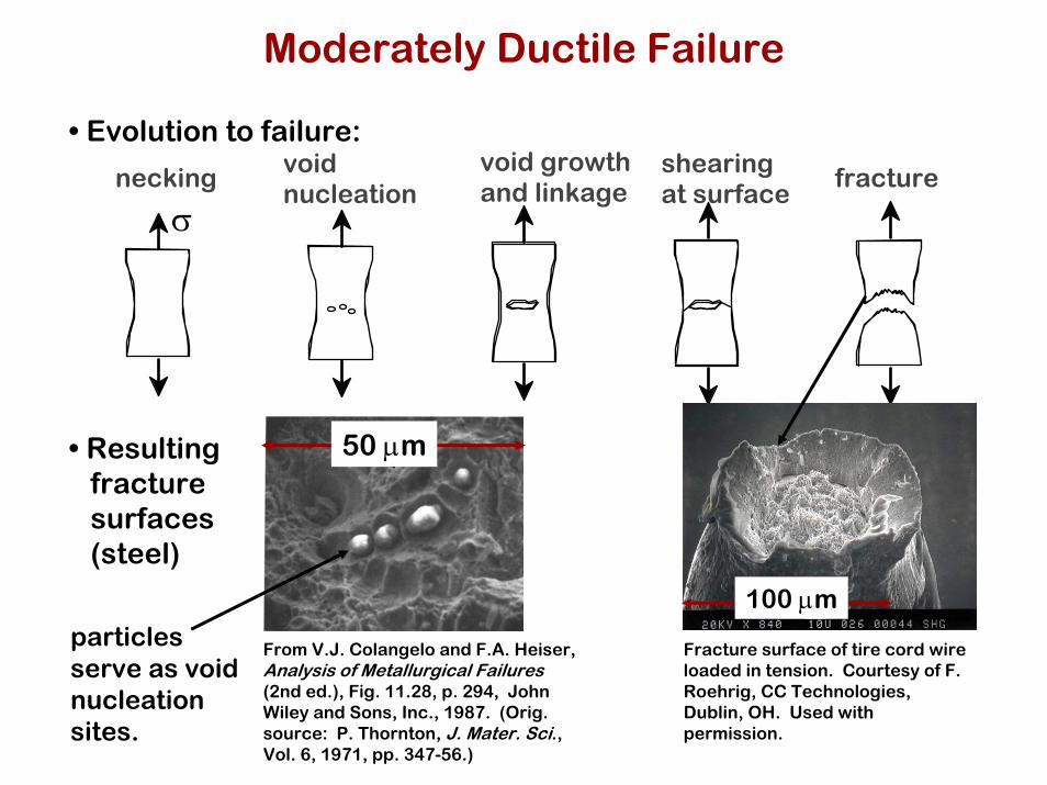
Moderately Ductile Failure
• Evolution to failure:
necking void nucleation
void growth and linkage
shearing at surface
fracture
σ
• Resultingfracturesurfaces(steel)
50 µm
particlesserve as voidnucleationsites.
50 µm
100 µm
From V.J. Colangelo and F.A. Heiser, Analysis of Metallurgical Failures(2nd ed.), Fig. 11.28, p. 294, John Wiley and Sons, Inc., 1987. (Orig. source: P. Thornton, J. Mater. Sci., Vol. 6, 1971, pp. 347-56.)
Fracture surface of tire cord wire loaded in tension. Courtesy of F. Roehrig, CC Technologies, Dublin, OH. Used with permission.

“Cup-and-Cone” Fracture and Brittle Fracture
Cup-and-cone fracture in Al
Dimpling (Center) Dimpling (Edge)

Brittle Fracture Surfaces
• Intergranular(between grains)
• Intragranular(within grains)
Al Oxide(ceramic)
Reprinted w/ permission from
"Failure Analysis of Brittle Materials", p. 78.
Copyright 1990, The American Ceramic
Society, Westerville, OH. (Micrograph by R.M. Gruver and H.
Kirchner.)
316 S. Steel (metal)
Reprinted w/ permission from
"Metals Handbook", 9th ed, Fig. 650, p. 357.
Copyright 1985, ASM International, Materials Park, OH. (Micrograph
by D.R. Diercks, Argonne National Lab.)
304 S. Steel (metal)Reprinted w/permission from "Metals Handbook", 9th ed, Fig. 633, p. 650. Copyright 1985, ASM International, Materials Park, OH. (Micrograph by J.R. Keiser and A.R. Olsen, Oak Ridge National Lab.)
Polypropylene(polymer)Reprinted w/ permission from R.W. Hertzberg, "Defor-mation and Fracture Mechanics of Engineering Materials", (4th ed.) Fig. 7.35(d), p. 303, John Wiley and Sons, Inc., 1996.
3µm
4 mm160µm
1 mm(Orig. source: K. Friedrick, Fracture 1977, Vol. 3, ICF4, Waterloo, CA, 1977, p. 1119.)

Brittle Fracture Surfaces
Transgranular fracture(ductile cast iron)
Intergranular fracture
Fractography – study of fracture surfaces (usually SEM)

Brittle Fracture Surfaces
Brittle fracture surfaces
Arrows indicate origin
Fracture surface structure:Crack OriginCrack path

Ideal vs. Real Materials
• Stress-strain behavior (Room T):
σ
ε
E/10
E/100
0.1
perfect mat’l-no flaws
carefully produced glass fiber
typical ceramic typical strengthened metaltypical polymer
TS << TSengineeringmaterials
perfectmaterials
• DaVinci (500 yrs ago!) observed...--the longer the wire, the
smaller the load to fail it.• Reasons:
--flaws cause premature failure.--Larger samples are more flawed!
Reprinted w/ permission from R.W. Hertzberg, "Deformation and Fracture Mechanics of Engineering Materials", (4th ed.) Fig. 7.4. John Wiley and Sons, Inc., 1996.
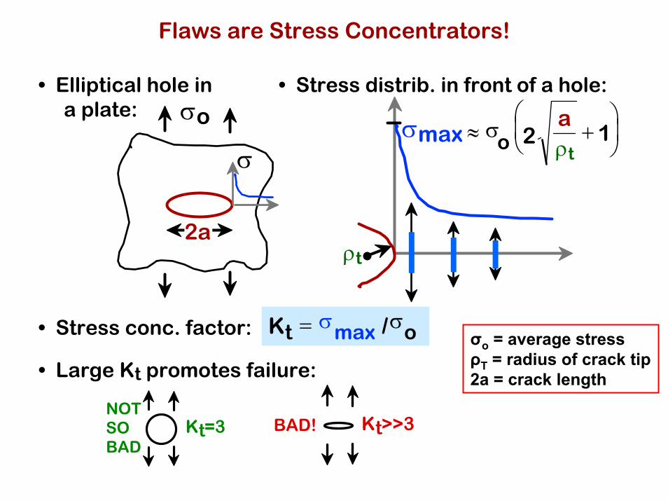
Flaws are Stress Concentrators!
• Elliptical hole ina plate:
• Stress distrib. in front of a hole:
• Stress conc. factor:
BAD! Kt>>3NOT SO BAD
Kt=3
σmax
ρt
≈ 2σo
a + 1⎛ ⎝ ⎜
⎞ ⎠ ⎟
ρtσ
σo
2a
Kt = σmax /σo
• Large Kt promotes failure:
σo = average stressρT = radius of crack tip2a = crack length

Engineering Fracture Design
• Avoid sharp corners!
r/h
sharper fillet radius
increasing w/h
0 0.5 1.01.0
1.5
2.0
2.5
Stress Conc. Factor, Ktσmax
σo=
Adapted from Fig. 8.2W(c), Callister 6e.(Fig. 8.2W(c) is from G.H. Neugebauer, Prod. Eng. (NY), Vol. 14, pp. 82-87 1943.)
r , fillet
radius
w
h
σo
σmax

When Does a Crack Propagate?
• ρt at a cracktip is verysmall!
σ
• Result: crack tipstress is very large.
• Crack propagates when:the tip stress is largeenough to make:
distance, x, from crack tip
σtip = K2π x
σtip
increasing K
K ≥ Kc

Geometry, Load, & Material
• Condition for crack propagation:
• Values of K for some standard loads & geometries:σ
2a2a
σ
aa
K = σ πa K = 1.1σ πa
K ≥ KcStress Intensity Factor:--Depends on load &
geometry.
Fracture Toughness:--Depends on the material,
temperature, environment, &rate of loading.
units of K :MPa mor ksi in
Adapted from Fig. 8.8, Callister 6e.

Fracture Toughness
Kc = Y σc (πa)½
Kc Fracture toughnessY Geometric factor (crack geometry)σc Critical stress for crack propagationa Crack length (depends on crack geometry)
Mode I (Tensile)
Mode II (Sliding)
Mode III (Tearing)
Crack Mode Designations

Graphite/ Ceramics/ Semicond
Metals/ Alloys
Composites/ fibersPolymers
5
KIc
(MP
a ·
m0
.5)
1
Mg alloysAl alloys
Ti alloys
Steels
Si crystalGlass-soda
Concrete
Si carbide
PC
Glass6
0.5
0.7
2
4
3
10
20
30
<100>
<111>
Diamond
PVC
PP
Polyester
PS
PET
C-C(|| fibers)1
0.6
67
40506070
100
Al oxideSi nitride
C/C( fibers)1
Al/Al oxide(sf)2
Al oxid/SiC(w)3
Al oxid/ZrO2(p)4Si nitr/SiC(w)5
Glass/SiC(w)6
Y2O3/ZrO2(p)4
Kcmetals
Kccomp
Kccer≈ Kc
poly
inc
rea
sin
g
Based on data in Table B5,Callister 6e.Composite reinforcement geometry is: f = fibers; sf = short fibers; w = whiskers; p = particles. Addition data as noted (vol. fraction of reinforcement):1. (55vol%) ASM Handbook, Vol. 21, ASM Int., Materials Park, OH (2001) p. 606.2. (55 vol%) Courtesy J. Cornie, MMC, Inc., Waltham, MA.3. (30 vol%) P.F. Becher et al., Fracture Mechanics of Ceramics, Vol. 7, Plenum Press (1986). pp. 61-73.4. Courtesy CoorsTek, Golden, CO.5. (30 vol%) S.T. Buljan et al., "Development of Ceramic Matrix Composites for Application in Technology for Advanced Engines Program", ORNL/Sub/85-22011/2, ORNL, 1992.6. (20vol%) F.D. Gace et al., Ceram. Eng. Sci. Proc., Vol. 7 (1986) pp. 978-82.
Fracture Toughness