summary wg8: beam diagnostics, instrumentation and technical systems
DESCRIPTION
Summary WG8: Beam Diagnostics, Instrumentation and Technical Systems. Graham Blair Hermann Schmickler Manfred Wendt Thanks to all presenters, contributors and the audience!. Statistics. Seven sessions - PowerPoint PPT PresentationTRANSCRIPT

Summary WG8: Beam Diagnostics, Instrumentation
and Technical Systems
Graham Blair
Hermann Schmickler
Manfred Wendt
Thanks to all presenters, contributors and the audience!
10/22/2010 1IWLC2010 WG8 Summary

Statistics
• Seven sessions– Four sessions dedicated to
beam diagnostics, instrumentation and technical systems(what is NOT a “technical system”?)
– Three joint sessions with CLIC Drive Beam / CTF3, Low Emittance Transport, and MDI.
– 24 presentations, ~10-20 participants in the sessions.– No surprise: Many presentations CLIC specific, but:
some talks on ATF, ILC and general LC diagnostics & technologies
• This summary– Cannot cover all presentations– Some presentations were already summaries of many complex
R&D activities! (summary of summaries)
• Now in somewhat chronologic order:
10/22/2010 IWLC2010 WG8 Summary 2

3
What was done for the CDRIWLCIWLC
1- First iteration on requirements from Beam Dynamic – first iteration in 2008- Full set of specifications: More than 200kms of beamlines requiring > 50 000 instruments
Thibaut Lefevre: CLIC• Many beam instruments!
Calls for standardization• Tight specs (nm, fsec,…)• Many not in turn-key status,
R&D on laser wire, EOS, …
10/22/2010 IWLC2010 WG8 Summary

CLIC/CTF3 BPMs
10/22/2010 IWLC2010 WG8 Summary 4
Dipole-mode “BPM” resonator& waveguide
Monopole-mode “REF” resonator
Quad
• Drive Beam BPM(Steve Smith)– Integrated with quad– Simple stripline BPM,
need ~40000!– <1 μm resolution (single
bunch, nom. charge)– Detailed analysis, incl.
read-out electronics & wakepotentials!
• Main Beam BPM (CERN/Fermilab)– WG-loaded cavity BPM, plus reference resonator.– <50 nm temporal resolution– <50 nsec time resolution (low-Q)– Design adapted to CTF3 bunch frequencies:
15 GHz resonators

First RF Measurements
10/22/2010 IWLC2010 WG8 Summary 5
1 1.1 1.2 1.3 1.4 1.5 1.6 1.7 1.8 1.9 2-100
-90
-80
-70
-60
-50
-40
-30
WG-Coupled Signals
0 mm
0.5 mm
1 mm
2 mm
Frequency [GHz]
Rela
tive
signa
l lev
el [d
B]
dipole-mode (Qℓ ≈ 290)
suppressedmonopole-mode
Injection response(sync tune subtracted)
• ILC Cold Cavity BPM– Dipole (BPM) & monopole (REF) read-out– Prototype finalized (“warm” dimensions)– RF characterization underway– ILC cryomodule compatible (type III+ or
IV)• ATF damping ring BPM read-out R&D– Analog / digital system w. integrated CAL– Resolution: <10 μm (TBT), <0.5 μm (NB)

CLIC Beam Profile: ODR
10/22/2010 IWLC2010 WG8 Summary 6
x
-4 -3 -2 -1 0 1 2 3 4
y
-4
-3
-2
-1
0
1
2
3
4
FDRBDR
e
h
• Thibaut Lefevre: Optical Diffraction Radiation– Simpler (and cheaper!) than laser wire– Non-invasive– Impact parameter vs. beam energy– Sensitivity & photon yield vs. beam energy
(need to go to soft-X/UV range for 1 μm resolution)– R&D activities in collaboration with CESR-TA

Summary of ATF2 Diagnostics
10/22/2010 IWLC2010 WG8 Summary 7
• Toshiaki Tauchi: ATF2 Diagnostics R&D– FONT feedback system:
beam jitter reduction 2.1 -> 0.4 μm– Laser wire: 3.5 μm resolution!– Four OTR systems with < 2μm resolution.– S-Band & C-Band cavity BPMs
C-Band performance: 200-400 nm resolution with attenuators25 nm resolution without attenuator!
– S-Band tilt monitor30 nrad expected resolution
– Shintake IP Laser interferometerfirst measurements: ~300 nm resolution
– IP cavity BPM<10 nm resolution (world record!)Goal: 2 nm
BUT (joint session with MDI):– CLCI IP BPMs require 13 pm resolution (?!)
(for 10 sec integration time)this BPM also needs BbB capability
8.7 nm position resolution!

More Diagnostics…
• Laura Corner: Fiber lasers– Photonic crystal fibers:
large core, single mode– Good spatial quality (M2<1.1), <2 nm spectral
spread, high power, low jitter, etc.– Burst mode amplification up to 100 μJ
• Anne Dabrowski: Long. Diagnostics– Technology choices vs. location
( Streak camera, EOS, CDR, RF detector)– Bunch length vs. bunch profile– (Personal remark: RF deflector?)
• Rogelio Tomas Garcia: BDS specs– CLIC BDS layouts, diagnostics requirements,
etc., & polarization measurements
10/22/2010 IWLC2010 WG8 Summary 8
Courtesy L. Søby, CERN

9
2% luminosity loss for- Gradient error of 10-3
- Phase error of 0.3o
- Main beam current stability of 0.1-0.2%
Need to stabilise Drive Beam
- Current – 7.5 10-3
- Bunch length – 1%
-Phase jitter from DR: 0.2o @ 1GHz- Phase jitter of BC1: 0.08o @ 4 GHz- Phase jitter of BC2 : 0.2o
@ 12GHz:-Phase error from DB accelerator: : 0.05o @ 1GHz
-Phase jitter from DR: 0.2o @ 1GHz- Phase jitter of BC1: 0.08o @ 4 GHz- Phase jitter of BC2 : 0.2o
@ 12GHz:-Phase error from DB accelerator: : 0.05o @ 1GHz
10/22/2010 IWLC2010 WG8 Summary

Amplifiers for CLIC Drive Beam Phase Correction
Philip Burrows, John Adams Institute, Oxford University
for Colin PerryBased on discussion in August 2009Speed: 10nsKickers: stripline kickers, 20mm clear aperture, 1m longDeflection: +/-720μrad at each bend - divided over 4 kickers = +/-180μrad at eachAmplifier architecture: modular, MOSFET
dipole magnet
1m kicker
250kW amp
8m5m8m NOT TO SCALE
It can be done – but looks very expensive !4 kickers at each bend, 250kW peak power amplifier to each kicker, 56 amplifier modules / amplifieramplifier cost: £75K per 250kW amplifier *** This is all very very approximate ***768 amplifiers total, 200MW total peak power: - SYSTEM COST: £60M (perhaps +/-£30M)
Good option to study vacuum tubes as an alternative to solid
state amplifiers !

11
‘First Clients’
‘Limitations’
‘Relevant technologies’
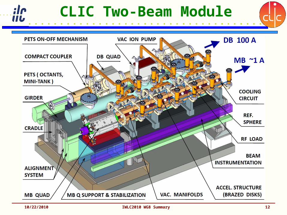
CLIC Two-Beam Module
10/22/2010 IWLC2010 WG8 Summary 12

CLIC TB Module (cont.)
• Five talks– Alexander Samoshkin: Integration– Germana Riddone: Prototyping for CTF3– Cedric Garion: Vacuum system– Michele Modena: Magnets– Marc Vanden Eynden: Data acquisition & control
• Very advanced design status (impressive!)– Many design details and solutions presented– Very compact, complex mechanics– Extremely tight tolerances!– Solutions for assembly and installation– Need low-power data acquisition concept.
10/22/2010 IWLC2010 WG8 Summary 13

CLIC Low Emittance Transport
• Joint session WG7+8• Four presentations with focus on:
– Alignment• Helene Mainaud-Durand: Pre-Alignment Studies• Thomas Touze: Metrological Reference Network
– Stabilization• Kurt Artoos: Status and plans• Christophe Collette: Hard or Soft? (active dampers)
10/22/2010 IWLC2010 WG8 Summary 14

Results from simulations very promising
For stabilization (on left),
for active pre-alignment (on right)
15

Experimental results very promising
For stabilization (on left), for active pre-alignment (on right)
Helene MAINAUD DURAND

Machine Protection System
• Two presentations:– Marc Ross: ILC MPS– Micheal Jonker: CLIC MPS
• Remarkable discussion– Neither beam energy (multi
GeV), nor beam power (multi MW), but: power density is destructive
• CLIC main beam: 10000 x “safe beam”
– Needs passive and active protection systems, pilot bunch concept, AND: A balanced beam-line design!
10/22/2010 IWLC2010 WG8 Summary 17
Single pulse damage in 1.4 mm Cu

Last Slide
10/22/2010 IWLC2010 WG8 Summary 18
THANK YOU!

Backup
10/22/2010 IWLC2010 WG8 Summary 19

Requirements and steps towards feasibility
For stabilization (on left), for active pre-alignment (on right)
Helene MAINAUD DURAND
Helene MAINAUD DURAND10/22/2010 20IWLC2010 WG8 Summary

Strategy…
For stabilization (on left), for active pre-alignment (on right)
Helene MAINAUD DURAND
Helene MAINAUD DURAND
10/22/2010 21IWLC2010 WG8 Summary
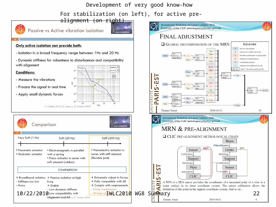
Development of very good know-how
For stabilization (on left), for active pre-alignment (on right)
Helene MAINAUD DURAND
10/22/2010 22IWLC2010 WG8 Summary

Still a lot to do…
For stabilization (on left),
for active pre-alignment (on right)
Helene MAINAUD DURAND
10/22/2010 23IWLC2010 WG8 Summary