summer training report - kfupmfaculty.kfupm.edu.sa/ee/samir/summer training/musaad daghriri.pdf ·...
TRANSCRIPT

King Fahd University of Petroleum & Minerals
Electrical Engineering Department
SUMMER TRAINING REPORT
SPCC
South Province Cement Company
Name: Musaad Yahya Daghriri
ID: 200635920
Date: 2010-10-12

1
TABLE OF CONTENT
TAPLE OF CONNTENT 1
List of Tables and Figures 2
I. INTRODUCTION 3
1.1 Overview about Cement Contains 3
II. PRODUCTION STEPS 4
2.1 Quarry 4
2.2 Quality Control 4
2.3 Crusher Area 4
III. MOBILE CRUSHER 5
3.1 The Process of Mobile Crusher 5
3.2 How is Mobile Crusher working? 5
3.3 Power Plant 6
IV. PROGRAMMABLE LOGIC CONTROLLER (PLC) 8
4.1 Basic Informa>on about PLC 9
4.2 PLC Programming 10
4.3 Example of writing program using CSF 12
V. DETECTORS 13
5.1 Thermocouple 13
5.2 Resistance Temperature Detectors (RTD's) 14
5.3 Comparison of RTD's and Thermocouples 15
VI. CONCLUSION 15

2
LIST OF TABLES AND FIGURES
Tables:
Table 1: Types of PLC's and their symbols. 8
Table 2: Wire calibra>on 13
Table 3: Comparison between thermocouple and RTD's 15
Figures:
Figure 1: Cement Ingredients 3
Figure 2: Mobile Crusher 5
Figure 3: The Generators 6
Figure 4: Power Distribution 7
Figure 5: MCC of Finish Mill 7
Figure 6: PLC unit 9
Figure 7: Siemens MASTERGUARD 10
Figure 8: PLC Program using CSF 12
Figure 9: Thermocouple 13
Figure 10: RTD 14

3
INTRODUCTION
This report will discuss the summer training program which has number of tasks that
done through eight weeks in one of south province company. This company is
Southern Province Cement Company (SPCC) which is divided into three main
departments. These departments are Works Manager Department, Production
Department and Maintenance Department.
Overview about Cement Contains
The cement Ingredients is containing 4 main types of raw material in addi>on of
some additive materials like alkali. The Lime Stone, Sand Stone and Iron Ore will mix
to each other through process step then we will get the Clinker. The Clinker, Gypsum
and Alkali will mix to each other through process step then as result it will give the
final cement product.
Figure 1: Cement Ingredients
CEMENT
INGREDIENTS
Gypsum &
additive
material
Iron Ore Sand Stone
Lime Stone
( High & Low )

4
PRODUCTION STEPS
Quarry
This place is the most important and most dangerous in the plant. It is important
because it is the source of the main Raw Material which is Lime Stone either high
lime or low lime. On the other hand, it is dangerous because of the explosive work to
get those materials from the mountain. The control side of this part especially in
High and Low Lime Reclaimers is using PLC Unite "S5 PLC".
Quality Control
In this department there are two types of machine that analyze the materials. Firstly,
Gama Analyzer is analyze the lime stone and to find out the ratios of the elements.
The idea of this machine is related to the electron of the element. Secondly, X-Ray
instrument which control the Raw material. Also, there is some other equipment like
small mills to prepare the sample which coming from the Raw Mills and Finish Mills.
In addition, there is one system is used to call the sample from Mills. The type of this
system is pneumatic system.
Crusher Area
There are six type of crusher depending on their specific work. The first type is
Mobile Crusher that is moving from place to another according to the availability of
needed source. The other type is locally crusher which consider as a multi step
crusher as following:
1- Primary Crusher.
2- Secondary Crusher.
3- Sand stone Crusher.
4- Iron Ore Crusher.
5- Gypsum Crusher.

5
MOBILE CRUSHER
This crusher is receiving the raw material of lime stone through the apron feeder
then the crushing process will takeover. Inside the mobile crusher rotor there are 12
rows in each row there are 7 hummers for crushing the huge rock to the required
size. From the crusher to the plant the material is transferring through a long belt
called "B1". This belt by three motors one in tail and two in head of belt.
Figure 2: Mobile Crusher
The Process of Mobile Crusher
Loading the track from the mountain Apron Feeder Vibrator The Main
Crusher Discharge Belt A1A Belt A1B Belt A2 Belt Surge Bin#1 Long
belt B1 Surge Bin#2 B2 Belt B27 Belt B127 Belt B204 Gama B30 Belt
How is Mobile Crusher working?
It is working in special way that starts from last part (B30 Belt) gradually to first part
(Apron Feeder) and stop reversely from Apron Feeder to B30 Belt. This is happening
to skip the problem of accumulating the material on the belt and inside the crusher
which causing many problem. Also, if any part of the system is stop for any reason
then all parts comes before this part will stop automatically and gradually one by
one from last to first. For example, if A2 Belt is cut then the system stop star>ng
from A1B then A1A then Discharging Belt then the main crusher then the vibrator
and finally the Apron feeder. Other belt following belt A2 will not stop and it will
continue work until transfer all material then stop. On the other hand, the system

6
does not start working again until it check all parts of system are ready to work
otherwise it will not work. PLC S5 is doing these en>re job including checking,
starting and stopping. There are two special systems that controlling the tension of
the belts according to the weather or the amount of material transferring by that
belt. The system is chosen according to the length of the belt. If the belt is short,
counter system will used which using weight to do the aim as shown in the figure.
Motor system is using for long belt like B1 Belt.
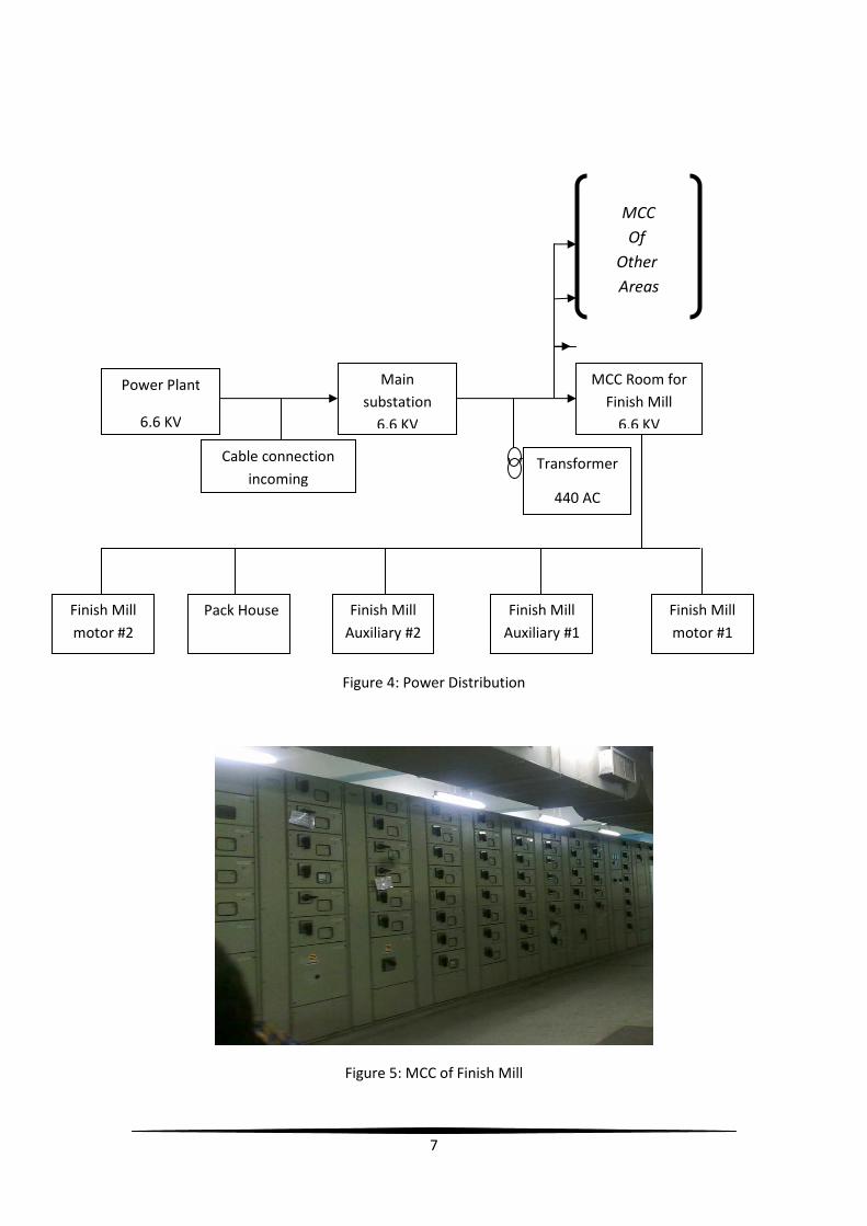
Power Plant
This department is the main supply of power for all branches of the plant. The power
is providing from main power plant to the substation and from the substation power
will distribute to each area in the plant as shown in the figure. In the power plant
there are 9 numbers of generators as below
1- 8 generators have capacity of 7.3 MW using relay system.
2- 1 generator have capacity of 10.9 MW using Siemens PLC system.
Figure 3: The Generators
On the other hand, It is easy to find out the pipe line which one for what, because
each line have different color each color for different purpose as below
1- Blue color pipe line using for water.
2- Yellow color pipe line using for oil.
3- Brown color pipe line using for fuel.
4- White color pipe line using for Air.
7
Figure 4: Power Distribution
Figure 5: MCC of Finish Mill
Power Plant
6.6 KV
Main
substation
6.6 KV
MCC Room for
Finish Mill
6.6 KV
Cable connection
incoming Transformer
440 AC
Finish Mill
motor #2
Pack House Finish Mill
Auxiliary #2
Finish Mill
Auxiliary #1
Finish Mill
motor #1
MCC Of
Other
Areas

8
PROGRAMMABLE LOGIC CONTROLLER (PLC)
As we know since long time ago the people start thinking to find the best way that it
can help them to control their projects and work. Then, the start using the ON/OFF
contactor and day by day they find their need which is the PLC. The PLC started as
simple control program then people started working in to improve their work.
Finally, they came up with a step 5 PLC which has three different models (95u , 115u
, 900) and it was the best in that >me un>l step 7 comes up also with three different
model (200,300,400). Nowadays, some companies are s>ll using a step 5 like SPCC.
The Plants that used "S5 PLC" system in SPCC
1- High and Low Lime Reclaimers.
2- Mobile crusher.
3- Raw mills 1&2.
4- Kilns 1&2.
5- Finish mill.
6- Pack house.
7- Paper sacks.
In SPCC, there are three different PLC systems according to its producer company.
These three producers are Siemens, Mitsubishi and Alum Bradley. Each one of these
type has its special program and symbols as shown in the following table:
Type Symbol Refer to
SIEMENS I E Input
Q A Output
MITSUBISHI X Input
Y Output
ALUM BRADLEY I Input
Q Output
Table 1: Types of PLC's and their symbols.

9
Figure 6: PLC unit
Basic Information about PLC
PLC system contains three main units. Power supply is the first unit that provides
power to other units. The second unit is the CPU unit which has all programs and
consider as the brain of the all system. Then, the Input – Output unit (I \O) is the
third unit and in this unit inputs is ordering like (I0.0,I0.1,… etc.) and output
(Q0.0,Q0.1,…etc.) for Siemens. There is also a reserve power supply in case of a
sudden stop of the power that make a lot of problem to the PLC system because it
needs to stop gradually but not suddenly. Also, The PLC system is considered as
operator for other machines and equipment that causes a lot of danger if it is
stopped in wrong way like motors. In SPCC, they use Siemens MASTERGUARD PLC
can deal with both type of signal either continuous or digital depending in the
application itself. For example, continuous signal is used in temperature detectors
because the temperature is considered as linear relation with continuous signal.
There are three type of programming or sometimes called display Formats. These
three display formats are explained as below:
1. Ladder Diagram (LAD) which consider as graphical representation of a program
using the usual symbols. The symbols represent an interrogation of a voltage
state ( voltage present, voltage not present) of a sensor or a control element.
2. Control System Flowchart (CSF) is simply block diagram of the automation task
using symbols for the individual functions.
3. Statement List (STL) is the program represented by a list of mnemonics.

10
Figure 7: Siemens MASTERGUARD
Notes
• In principle, the display formats can be intermingled on the PG. However,
not all STL function can be converted into graphical forms CSF and LAD, all
programs created in LAD or CSF can be converted into STL.
• The programming unit stores all programs in programmable controller's
memory in machine code, regardless of the format that used to program.
PLC Programming
In SPCC, I learned how to program a PLC using SIMATIC manager software. I did
some simple program and I interact with the block diagram and I got good
experience in how to control huge number of motors and timers.
How to open and work with Engineering Station PLC Using SIMATEC
1. Open the engineering station PLC computer using the key.
2. AOer opening the computer select S5 from the tool bar.
3. AOer selec>ng S5 one page will come up with language selec>on. Press "E"
from the keyboard for English language.
4. Now, PLC page will be shown and you can work offline mode as well as online
depending in the programmer himself whether he want to apply the
commands directly to the system or not. To set online or offline you should
follow the steps as follow:

11
• Project Load D Simatic Jizan then select the work
direction that you need to work with and this will be the setup of
page one.
• Project seQng page2 from page2 you can change the
status to online.
• If page 2 is offline and you need to check one item Editor step5
block in the program file the dialog box will open then write
the item PB number press enter five times.
• If page 2 online and you need to check one item Test block
status the dialog box will open then write the item PB number
press enter five times.
Steps to make a logic 1 or bypass:
• Press Edit from down tool bar or press F6 from the keyboard.
• To change the input status to logic 1, use the cursor key to bring the Edit
box up to the input that you need to make logic 1.
• Now you can change the input to logic 1 by pressing "-" key from the
keyboard. In step you have two choice as below:
� You can change the input to logic 1 by wri>ng command "F1.1". in
this way you have to press "-" key one >me only then write F1.1
then press enter then press "Ins" key then yes.
� You can change the input to logic 1 by wri>ng command "LOG1", in
this way you have to press "-" key two times then write LOG1 then
press "Enter" then press "Ins" key then yes.
Timers in the step 5 PLC:
• KT xxx.n
• xxx have value from 000 up to 999.
• n have value from 0 up to 3
� K999.0 999/100
� K999.1 999/10
� K999.2 999/1
� K999.3 999*10
Way of how to change the value of the timer in the PLC:
Edit use the cursor key to bring the edit box to the timer value do the
changing press enter.

12
Example of writing program using CSF which I did and checked by the
SPCC supervisor:
Write a program that runs three motors as follow:
1. When start buTon is pressed motor 1 run.
2. After motor 1 run by 5 seconds motor 2 run.
3. AOer motor 2 run by 5 seconds motor 3 run.
4. When stop buTon is pressed motor 3 stop.
5. AOer motor 3 stop by 5 seconds motor 2 stop.
6. AOer motor 2 stop by 5 seconds motor 1 stop.
Figure 8: PLC Program using CSF
13
DETECTORS
There is many type of detector but I will concentrate in temperature sensors which I
dealt with.
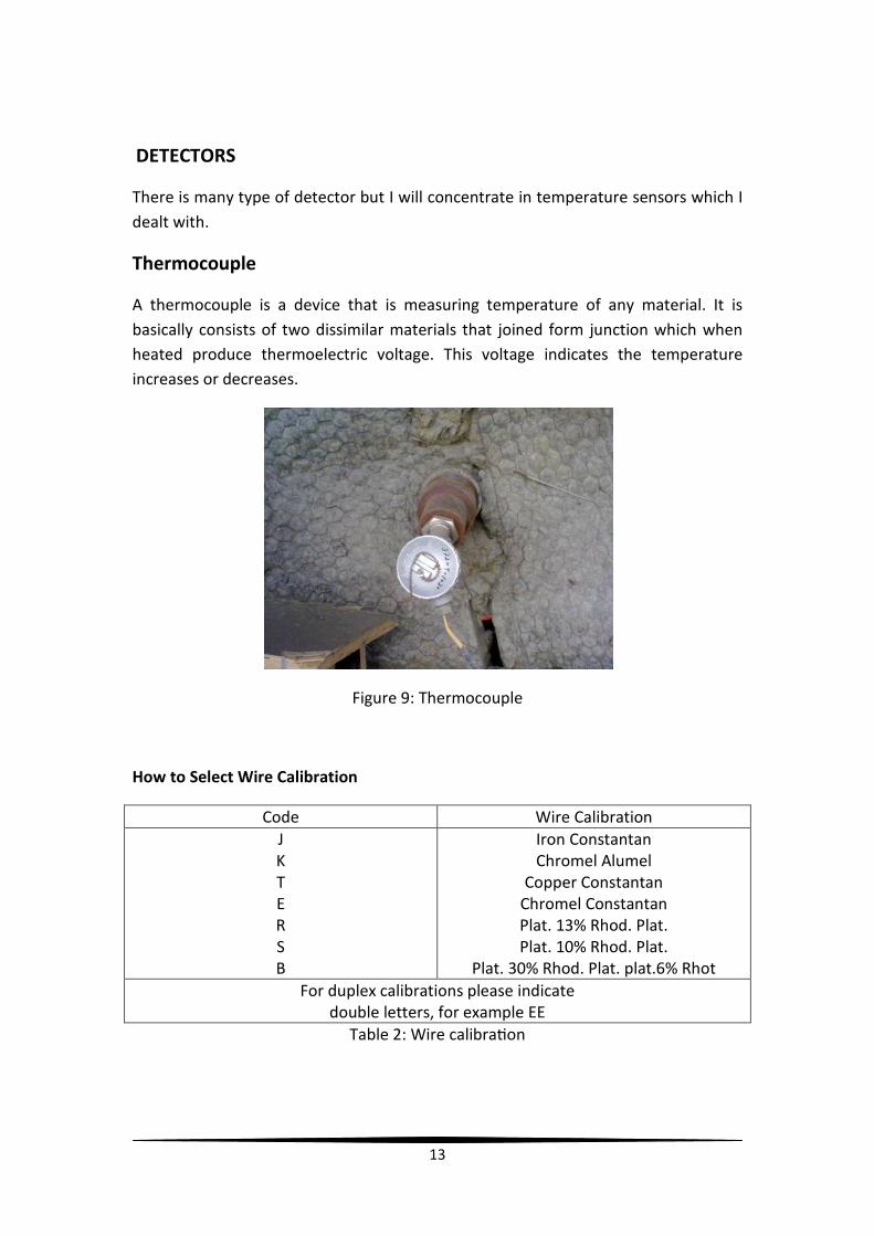
Thermocouple
A thermocouple is a device that is measuring temperature of any material. It is
basically consists of two dissimilar materials that joined form junction which when
heated produce thermoelectric voltage. This voltage indicates the temperature
increases or decreases.
Figure 9: Thermocouple
How to Select Wire Calibration
Code Wire Calibration
J
K
T
E
R
S
B
Iron Constantan
Chromel Alumel
Copper Constantan
Chromel Constantan
Plat. 13% Rhod. Plat.
Plat. 10% Rhod. Plat.
Plat. 30% Rhod. Plat. plat.6% Rhot
For duplex calibrations please indicate
double letters, for example EE
Table 2: Wire calibra>on

14
Resistance Temperature Detectors (RTD's)
Resistance temperature detectors senses heat based on the principle that a change
in temperature results in a corresponding change in the resistance of a wire. When a
small excitation current is passed along the element, the voltage is then measured
and converted to units of temperature.
Figure 10: RTD

15
Comparison of RTD's and Thermocouples
The advantages of using RTD's are numerous. They offer high accuracy, repeatability
and stability. Another advantage is that cold junction compensation is unnecessary.
Here is a brief summary of some of the advantages and disadvantage of both
thermocouples and RTD's:
Thermocouple RTD's
Accuracy Limits of error wider than
RTD's
Limits of error much closer
than thermocouples
Ruggedness Excellent, will not affect life
expectancy of the probe
Somewhat sensitive to
strain, Vibration, shock and
pressure
Temperature -328 to 4200F
-200 to 2315C
-50 to 1500F
-45 to 593C
Response
Can be made small enough
for millisecond response
time
Slower , Thermal mass
results in a response time of
seconds or more
Sensitivity Can be made tip sensitive
Cannot rapidly be made tip
sensitive. Thermal mass
prevents tip sensitive
construction.
linearity Non-linear Linear over a wide operating
range
Table 3: Comparison between thermocouple and RTD's
CONCLUSION
This period of summer training is very productive. Many things were learned in these
8 weeks taken in SPCC. In this conclusion, things were learned will be listed.
I learned how to deal with PLC system and many thing related to PLC. Also, I got a lot
of information related to the sensors that used in SPCC and about some types of
controller like PID controller. I learned about the power distribution in the plants. To
sum up, I really concentrate on the control systems that used in SPCC.

16