sunny island 8.0h/6.0h / sunny remote control - … · sunny remote control operating manual. sma...
TRANSCRIPT

SI80H-BE-BEN120810 | TBEN-SI80H | Version 1.0 EN
Off-grid InverterSUNNY ISLAND 8.0H/6.0HSUNNY REMOTE CONTROLOperating Manual


SMA Solar Technology AG Table of Contents
Operating Manual SI80H-BE-BEN120810 3
Table of Contents1 Information on this Document. . . . . . . . . . . . . . . . . . . . . . . 72 Safety . . . . . . . . . . . . . . . . . . . . . . . . . . . . . . . . . . . . . . . . . . 92.1 Intended Use. . . . . . . . . . . . . . . . . . . . . . . . . . . . . . . . . . . . . . . . 92.2 Target Group Qualifications . . . . . . . . . . . . . . . . . . . . . . . . . . . 102.3 Safety Precautions. . . . . . . . . . . . . . . . . . . . . . . . . . . . . . . . . . . 113 Product Description . . . . . . . . . . . . . . . . . . . . . . . . . . . . . . 133.1 Sunny Island 8.0H / 6.0H . . . . . . . . . . . . . . . . . . . . . . . . . . . . 133.2 Type Label . . . . . . . . . . . . . . . . . . . . . . . . . . . . . . . . . . . . . . . . 143.3 Off-Grid Inverter Control Panel . . . . . . . . . . . . . . . . . . . . . . . . . 163.4 Sunny Remote Control . . . . . . . . . . . . . . . . . . . . . . . . . . . . . . . 183.5 Service Interface SD Card . . . . . . . . . . . . . . . . . . . . . . . . . . . . 193.6 Time-Controlled Operation . . . . . . . . . . . . . . . . . . . . . . . . . . . . 194 Operating the Off-Grid Inverter with
Sunny Remote Control . . . . . . . . . . . . . . . . . . . . . . . . . . . . 204.1 Display Modes . . . . . . . . . . . . . . . . . . . . . . . . . . . . . . . . . . . . . 204.2 Standard Mode . . . . . . . . . . . . . . . . . . . . . . . . . . . . . . . . . . . . 214.2.1 Display of Operating States . . . . . . . . . . . . . . . . . . . . . . . . . . . . . . . . . . . . . 214.2.2 Display Page during Operation . . . . . . . . . . . . . . . . . . . . . . . . . . . . . . . . . . 224.3 User Mode . . . . . . . . . . . . . . . . . . . . . . . . . . . . . . . . . . . . . . . . 274.3.1 Display Pages for Operation. . . . . . . . . . . . . . . . . . . . . . . . . . . . . . . . . . . . . 274.3.2 Display Pages . . . . . . . . . . . . . . . . . . . . . . . . . . . . . . . . . . . . . . . . . . . . . . . . 274.3.3 Setting Pages. . . . . . . . . . . . . . . . . . . . . . . . . . . . . . . . . . . . . . . . . . . . . . . . . 284.3.4 Selecting Display Pages . . . . . . . . . . . . . . . . . . . . . . . . . . . . . . . . . . . . . . . . 294.3.5 Operating and Configuring the Off-Grid Inverter . . . . . . . . . . . . . . . . . . . . . 304.4 Installer and Expert Mode . . . . . . . . . . . . . . . . . . . . . . . . . . . . 324.4.1 Switching to Installer Mode . . . . . . . . . . . . . . . . . . . . . . . . . . . . . . . . . . . . . 324.4.2 Switching to Expert Mode. . . . . . . . . . . . . . . . . . . . . . . . . . . . . . . . . . . . . . . 32

Table of Contents SMA Solar Technology AG
4 SI80H-BE-BEN120810 Operating Manual
4.4.3 Menus in Installer and Expert Mode. . . . . . . . . . . . . . . . . . . . . . . . . . . . . . . 334.4.4 Parameter Page in Installer and Expert Mode . . . . . . . . . . . . . . . . . . . . . . . 334.4.5 Selecting Menus and Parameters . . . . . . . . . . . . . . . . . . . . . . . . . . . . . . . . . 344.4.6 Setting the Parameters. . . . . . . . . . . . . . . . . . . . . . . . . . . . . . . . . . . . . . . . . . 354.4.7 Directly Accessing Parameters . . . . . . . . . . . . . . . . . . . . . . . . . . . . . . . . . . . 36
5 Starting and Stopping the Off-Grid System . . . . . . . . . . . 375.1 Switching On the Off-Grid Inverter . . . . . . . . . . . . . . . . . . . . . . 375.2 Starting the Off-Grid System . . . . . . . . . . . . . . . . . . . . . . . . . . . 375.3 Stopping the Off-Grid System. . . . . . . . . . . . . . . . . . . . . . . . . . 385.4 Switching Off the Off-Grid Inverters . . . . . . . . . . . . . . . . . . . . . 395.5 Tripping the Emergency Disconnection of the Off-Grid System . . . 395.6 Setting Time-Controlled Inverter Operation. . . . . . . . . . . . . . . . 406 Saving Data and Updating Firmware . . . . . . . . . . . . . . . 416.1 Inserting the SD Card . . . . . . . . . . . . . . . . . . . . . . . . . . . . . . . . 416.2 Saving and Loading Parameters . . . . . . . . . . . . . . . . . . . . . . . . 416.3 Saving the Event History and Error History . . . . . . . . . . . . . . . . 426.4 Updating the Firmware . . . . . . . . . . . . . . . . . . . . . . . . . . . . . . . 426.5 Displaying the Status of the SD Card . . . . . . . . . . . . . . . . . . . . 436.6 Removing the SD Card . . . . . . . . . . . . . . . . . . . . . . . . . . . . . . . 436.7 Displaying the Content of the Files . . . . . . . . . . . . . . . . . . . . . . 437 Manually Controlling the Generator . . . . . . . . . . . . . . . . 457.1 Starting the Generator with Sunny Remote Control . . . . . . . . . 457.2 Stopping the Generator with Sunny Remote Control . . . . . . . . 457.3 Starting the Generator without Autostart Function . . . . . . . . . . 467.4 Stopping the Generator without Autostart Function . . . . . . . . . 468 Disconnecting the Off-Grid Inverter from
Voltage Sources . . . . . . . . . . . . . . . . . . . . . . . . . . . . . . . . . 47

SMA Solar Technology AG Table of Contents
Operating Manual SI80H-BE-BEN120810 5
9 Cleaning and Maintenance . . . . . . . . . . . . . . . . . . . . . . . . 489.1 Cleaning the Enclosure of the Off-Grid Inverter . . . . . . . . . . . . 489.2 Cleaning the Sunny Remote Control . . . . . . . . . . . . . . . . . . . . . 489.3 Performing a Manual Equalisation Charge . . . . . . . . . . . . . . . 489.4 Checking the Function. . . . . . . . . . . . . . . . . . . . . . . . . . . . . . . . 499.5 Checking the Connections . . . . . . . . . . . . . . . . . . . . . . . . . . . . 499.6 Checking and Maintaining the Battery . . . . . . . . . . . . . . . . . . . 509.7 Cleaning the Fans . . . . . . . . . . . . . . . . . . . . . . . . . . . . . . . . . . . 509.8 Replacing the Battery . . . . . . . . . . . . . . . . . . . . . . . . . . . . . . . . 5210 Troubleshooting . . . . . . . . . . . . . . . . . . . . . . . . . . . . . . . . . 5410.1 What to Do if an Error Occurs . . . . . . . . . . . . . . . . . . . . . . . . . 5410.2 Acknowledging a Generator Error . . . . . . . . . . . . . . . . . . . . . . 5610.3 Acknowledging Level 3 and 4 Errors . . . . . . . . . . . . . . . . . . . . 5610.4 Changing Slave Addresses in a Cluster . . . . . . . . . . . . . . . . . . 5610.5 Frequently Asked Questions . . . . . . . . . . . . . . . . . . . . . . . . . . . 5810.5.1 Questions on the Off-Grid Inverter . . . . . . . . . . . . . . . . . . . . . . . . . . . . . . . . 5810.5.2 Questions on the Sunny Remote Control. . . . . . . . . . . . . . . . . . . . . . . . . . . . 5910.5.3 Questions on the External Energy Source . . . . . . . . . . . . . . . . . . . . . . . . . . . 6010.5.4 Questions on the Battery . . . . . . . . . . . . . . . . . . . . . . . . . . . . . . . . . . . . . . . . 6110.5.5 Questions on Cluster Systems and Multicluster Systems . . . . . . . . . . . . . . . . 6210.6 Charging the Battery after Automatic Shutdown . . . . . . . . . . . 6311 Glossary . . . . . . . . . . . . . . . . . . . . . . . . . . . . . . . . . . . . . . . 6612 Contact . . . . . . . . . . . . . . . . . . . . . . . . . . . . . . . . . . . . . . . . 74

Table of Contents SMA Solar Technology AG
6 SI80H-BE-BEN120810 Operating Manual
SMA Solar Technology AG 1 Information on this Document
Operating Manual SI80H-BE-BEN120810 7
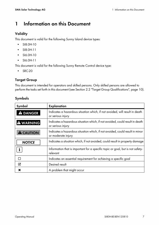
1 Information on this DocumentValidityThis document is valid for the following Sunny Island device types:
• SI8.0H-10• SI8.0H-11• SI6.0H-10• SI6.0H-11
This document is valid for the following Sunny Remote Control device type:• SRC-20
Target GroupThis document is intended for operators and skilled persons. Only skilled persons are allowed to perform the tasks set forth in this document (see Section 2.2 "Target Group Qualifications", page 10).
SymbolsSymbol Explanation
Indicates a hazardous situation which, if not avoided, will result in death or serious injuryIndicates a hazardous situation which, if not avoided, could result in death or serious injuryIndicates a hazardous situation which, if not avoided, could result in minor or moderate injuryIndicates a situation which, if not avoided, could result in property damage
Information that is important for a specific topic or goal, but is not safety-relevant
☐ Indicates an essential requirement for achieving a specific goal☑ Desired result✖ A problem that might occur

1 Information on this Document SMA Solar Technology AG
8 SI80H-BE-BEN120810 Operating Manual
Typographies
NomenclatureThis document refers to the Sunny Island as an off-grid inverter.Menus are presented as follows: menu number, hash, menu name (e.g. 150# Compact Meters).Parameters are presented as follows: menu number, dot, parameter number, and parameter name (e.g. 150.01 GdRmgTm). Parameters include both configurable parameters and parameters for displaying values.
Abbreviations
Typography Usage Examplebold • Display messages
• Parameters• Connections• Slots• Elements to be selected• Elements to be entered
• Connect PE to AC2Gen/Grid.• Select parameter
235.01 GnAutoEna and set to Off.
> • Several elements that are to be selected
• Select 600# Direct Access > Select Number.
[Button/Key] • Button on the inverter to be selected or pressed
• Press [ENTER]
Abbreviation Designation ExplanationAC Alternating Current -DC Direct Current -LED Light-Emitting Diode -QCG Quick Configuration Guide -

SMA Solar Technology AG 2 Safety
Operating Manual SI80H-BE-BEN120810 9
2 Safety2.1 Intended UseSunny IslandThe Sunny Island is a bidirectional off-grid inverter and forms a stand-alone grid.
Figure 1: Principle of an off-grid system with a Sunny Island and a Sunny Remote Control
Only use the Sunny Island in accordance with the information provided in the enclosed documentation. Any other use may result in personal injury or property damage.Life-threatening voltages occur in the Sunny Island.
• Never operate the Sunny Island without the enclosure lid in place.• Only skilled persons may open the Sunny Island.
The Sunny Island uses batteries for energy storage. The rated voltage of the battery must correspond to the DC input voltage. A fuse-switch-disconnector, e.g. a BatFuse must be installed between the battery and the Sunny Island.

2 Safety SMA Solar Technology AG
10 SI80H-BE-BEN120810 Operating Manual
DC loads and DC sources can be integrated in the off-grid system. The Sunny Island is not suitable for establishing a DC distribution network. The Sunny Island is not suitable for supplying life-sustaining medical devices.
• Never use the Sunny Island in systems in which a power outage might result in personal injury.The Sunny Island can control various components in an off-grid system via two multi-function relays, e.g. a load-shedding contactor. The multi-function relays are not suitable for controlling components which may place people at risk if the multi-function relays malfunction, e.g. if the battery chamber ventilation is not sufficiently redundant.The enclosed documentation is an integral part of this product.
• Read and adhere to the documentation.• Keep the documentation in a convenient place at all times for future reference.
Sunny Remote ControlYou can configure and control the off-grid system centrally with the Sunny Remote Control display. The Sunny Remote Control is only suitable for indoor use.
2.2 Target Group QualificationsOperatorsOperators must be instructed in the following areas by skilled persons:
• Dangers involved in handling electrical equipment• Operating an off-grid system• Safe handling of batteries• Safely switching off and disconnecting the off-grid system in case of an error• How to prevent unintentional restarting of an off-grid system• Maintaining and cleaning the off-grid inverter• Knowledge of and adherence to this manual and all the specified safety precautions
Skilled PersonsSkilled persons must have the following qualifications:
• Training in off-grid systems from SMA Solar Technology AG• Training in how to deal with the dangers and risks associated with installing and using electrical
devices and batteries• Training in the installation and commissioning of electrical devices• Knowledge and observance of the local standards and directives• Knowledge of and adherence to this document and all safety precautions
SMA Solar Technology AG 2 Safety
Operating Manual SI80H-BE-BEN120810 11
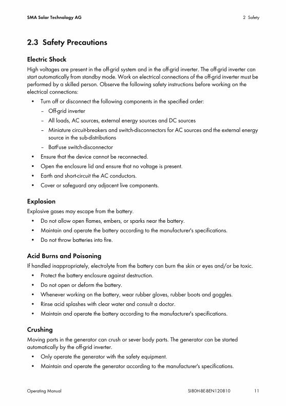
2.3 Safety PrecautionsElectric ShockHigh voltages are present in the off-grid system and in the off-grid inverter. The off-grid inverter can start automatically from standby mode. Work on electrical connections of the off-grid inverter must be performed by a skilled person. Observe the following safety instructions before working on the electrical connections:
• Turn off or disconnect the following components in the specified order:– Off-grid inverter– All loads, AC sources, external energy sources and DC sources– Miniature circuit-breakers and switch-disconnectors for AC sources and the external energy
source in the sub-distributions– BatFuse switch-disconnector
• Ensure that the device cannot be reconnected.• Open the enclosure lid and ensure that no voltage is present.• Earth and short-circuit the AC conductors.• Cover or safeguard any adjacent live components.
ExplosionExplosive gases may escape from the battery.
• Do not allow open flames, embers, or sparks near the battery.• Maintain and operate the battery according to the manufacturer's specifications.• Do not throw batteries into fire.
Acid Burns and PoisoningIf handled inappropriately, electrolyte from the battery can burn the skin or eyes and/or be toxic.
• Protect the battery enclosure against destruction.• Do not open or deform the battery.• Whenever working on the battery, wear rubber gloves, rubber boots and goggles.• Rinse acid splashes with clear water and consult a doctor.• Maintain and operate the battery according to the manufacturer's specifications.
CrushingMoving parts in the generator can crush or sever body parts. The generator can be started automatically by the off-grid inverter.
• Only operate the generator with the safety equipment.• Maintain and operate the generator according to the manufacturer's specifications.

2 Safety SMA Solar Technology AG
12 SI80H-BE-BEN120810 Operating Manual
Burn HazardsSome parts of the off-grid inverter enclosure can become hot during operation.
• During operation, touch the off-grid inverter on the enclosure lid only.
Short-circuit currents in the battery can cause heat build-up and electric arcs. Observe the following safety instructions before working on the battery.
• Remove watches, rings and other metal objects.• Use insulated tools.• Do not place tools or metal parts on the battery.

SMA Solar Technology AG 3 Product Description
Operating Manual SI80H-BE-BEN120810 13
3 Product Description3.1 Sunny Island 8.0H / 6.0HThe Sunny Island is a bidirectional off-grid inverter and forms a stand-alone grid.
Figure 2: Design of the Sunny Island 8.0H / 6.0H
The Sunny Island supplies AC loads in the stand-alone grid from a battery or charges the battery with the energy provided by sources on the AC side. AC sources in the stand-alone grid (e.g. PV inverters) supply loads and are used by the off-grid inverter to recharge the battery. In order to increase the availability of the stand-alone grid and reduce the battery capacity, the Sunny Island can use and control external energy sources (e.g. a generator) as an energy reserve.The Sunny Island supplies the loads with active power and reactive power. The loads may temporarily overload the Sunny Island. If there is a short circuit in the the stand-alone grid, the Sunny Island also briefly feeds in short-circuit currents to the stand-alone grid. As a result, the Sunny Island may trip miniature circuit-breakers. Miniature circuit-breakers only disconnect electric circuits that are affected by the fault.The off-grid system must be a TN or TT system. The Sunny Island does not support IT systems.
Position DesignationA Ventilation gridB Type labelC Control panelD Enclosure lid

3 Product Description SMA Solar Technology AG
14 SI80H-BE-BEN120810 Operating Manual
3.2 Type LabelThe type label identifies the off-grid inverter. The type label is located on the right-hand side of the enclosure.
Figure 3: Layout of the type label
The information on the type label is intended to help you use the inverter safely and receive better customer support from the SMA Service Line. The type label must remain permanently attached to the off-grid inverter.Symbols on the Type Label
Position Designation ExplanationA Type Device typeB Serial No. Serial number of the off-grid inverterC Device-specific characteristics ‒
Symbol Designation ExplanationDanger to life due to high voltages
The off-grid inverter operates at high voltages. All work on the off-grid inverter must be carried out by skilled persons (see Section 2.2).
SMA Solar Technology AG 3 Product Description
Operating Manual SI80H-BE-BEN120810 15
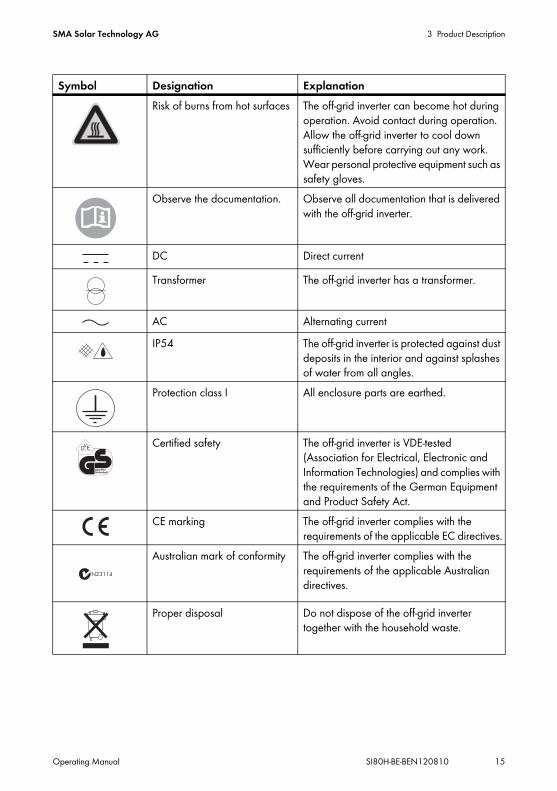
Risk of burns from hot surfaces The off-grid inverter can become hot during operation. Avoid contact during operation. Allow the off-grid inverter to cool down sufficiently before carrying out any work. Wear personal protective equipment such as safety gloves.
Observe the documentation. Observe all documentation that is delivered with the off-grid inverter.
DC Direct currentTransformer The off-grid inverter has a transformer.
AC Alternating currentIP54 The off-grid inverter is protected against dust
deposits in the interior and against splashes of water from all angles.
Protection class I All enclosure parts are earthed.
Certified safety The off-grid inverter is VDE-tested (Association for Electrical, Electronic and Information Technologies) and complies with the requirements of the German Equipment and Product Safety Act.
CE marking The off-grid inverter complies with the requirements of the applicable EC directives.
Australian mark of conformity The off-grid inverter complies with the requirements of the applicable Australian directives.
Proper disposal Do not dispose of the off-grid inverter together with the household waste.
Symbol Designation Explanation
VD E

3 Product Description SMA Solar Technology AG
16 SI80H-BE-BEN120810 Operating Manual
3.3 Off-Grid Inverter Control Panel
Figure 4: Structure of the control panel
Position Symbol Designation Status ExplanationA Start-stop button
TSS‒ Press the start-stop button to start or
stop the off-grid system. In display messages on the Sunny Remote Control, the start-stop button is referred to as TSS.
B Activation button ‒ Pressing the activation button will switch the off-grid inverter on. After switching the off-grid inverter on, it will enter the standby mode.
C Deactivation button
‒ Pressing the deactivation button will switch off the off-grid inverter.
D Inverter LED Off The off-grid inverter is switched off.Glowing green
The off-grid inverter is in operation.
Glowing orange
The off-grid inverter is in standby mode.
Glowing red The off-grid inverter has switched off due to an error.
Flashing quickly*
The off-grid inverter is not configured.
Flashing slowly**
The off-grid inverter is in sleep mode.

SMA Solar Technology AG 3 Product Description
Operating Manual SI80H-BE-BEN120810 17
E Grid LED Off No voltage is present at the connection of the external energy source.
Glowing green
External energy source is connected.
Glowing orange
The off-grid inverter synchronises the stand-alone grid to the external energy source.
Glowing red Error at the external energy source connection.
F Battery LED Glowing green
The battery charge level is over 50%.
Glowing orange
The battery charge level is between 50% and 20%.
Glowing red The battery charge level is below 20%.
G Standby ‒ Switching on and offH AC operation ‒ Start and stop the inverter operation
* flashing at intervals of 0.5 s to 1 s** flashing at intervals of 1.5 s to 2 s
Position Symbol Designation Status Explanation

3 Product Description SMA Solar Technology AG
18 SI80H-BE-BEN120810 Operating Manual
3.4 Sunny Remote ControlYou can configure and control the off-grid system centrally with the Sunny Remote Control display.
Figure 5: Design of the Sunny Remote Control
Position Designation ExplanationA Display Four-line display shows operating data (e.g. operating state
or display values) and events, warnings or errors of the off-grid inverter.The display's backlight is automatically deactivated after a short time of inactivity.
B Button Pressing the button will turn on the backlight, confirm parameters or switch the level within a menu. The return icon " " in the display tells you when you can perform an action by pressing the button.Turning the button will switch on the backlight, change parameters or navigate within a menu level.
C Slot for SD card ‒

SMA Solar Technology AG 3 Product Description
Operating Manual SI80H-BE-BEN120810 19
3.5 Service Interface SD CardThe SD card in the Sunny Remote Control stores data for the plant control and facilitates service work. The SD card is also used to update the firmware of the off-grid inverter. The following data is stored on the SD card:
• Parameter settings• At one-minute intervals, measurement data of the last 100 days from the areas:
– Battery– Off-grid inverter– External energy source– Stand-alone grid
• Events and faults of the last 100 days• Statistical values of the battery
SD cards can have storage capacities from 32 MB to 2 GB. The SD card must be formatted as FAT-16.
3.6 Time-Controlled OperationThe off-grid inverter can be operated with timer control. The following setting options are available:
• Time-controlled inverter operationIn time-controlled inverter operation, the off-grid inverter starts and stops automatically at the times set (see Section 5.6 "Setting Time-Controlled Inverter Operation", page 40).
• Time-controlled generator requestIn time-controlled generator requests, the off-grid inverter requests the generator at the set intervals (see the installation manual of the off-grid inverter).
4 Operating the Off-Grid Inverter with Sunny Remote Control SMA Solar Technology AG
20 SI80H-BE-BEN120810 Operating Manual
4 Operating the Off-Grid Inverter with Sunny Remote Control
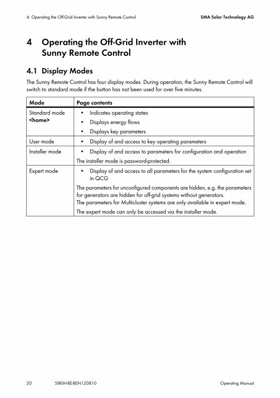
4.1 Display ModesThe Sunny Remote Control has four display modes. During operation, the Sunny Remote Control will switch to standard mode if the button has not been used for over five minutes.
Mode Page contentsStandard mode <home>
• Indicates operating states• Displays energy flows• Displays key parameters
User mode • Display of and access to key operating parametersInstaller mode • Display of and access to parameters for configuration and operation
The installer mode is password-protected.Expert mode • Display of and access to all parameters for the system configuration set
in QCGThe parameters for unconfigured components are hidden, e.g. the parameters for generators are hidden for off-grid systems without generators. The parameters for Multicluster systems are only available in expert mode.The expert mode can only be accessed via the installer mode.

SMA Solar Technology AG 4 Operating the Off-Grid Inverter with Sunny Remote Control
Operating Manual SI80H-BE-BEN120810 21
4.2 Standard Mode
4.2.1 Display of Operating States
Figure 6: Display of operating states (example "Standby")
Position Designation ExplanationA Standby The off-grid inverter is in standby mode or in time-controlled
mode.Boot The off-grid inverter is initialising.LBM 1 The off-grid inverter is in battery protection mode 1.LBM 2 The off-grid inverter is in battery protection mode 2.LBM 3 The off-grid inverter is in battery protection mode 3.Silent The off-grid inverter is in silent mode.Sleep The off-grid inverter is in sleep mode.Search The off-grid inverter is in search mode.Error The off-grid inverter is in error mode.Startup The off-grid inverter is starting up.Shutdown The off-grid inverter is shutting down.

4 Operating the Off-Grid Inverter with Sunny Remote Control SMA Solar Technology AG
22 SI80H-BE-BEN120810 Operating Manual
4.2.2 Display Page during Operation
Figure 7: Energy flows and status of the off-grid inverter (example)
Energy Flow Diagram
Figure 8: Energy flow diagram in standard mode (example)
Position DesignationA Energy flow diagramB Status of the stand-alone gridC Status of the off-grid inverterD State of charge of the batteryE Status of the external energy source
Position Designation Icon ExplanationA Battery Icon for batteryB Direction of energy
flowThe battery is supplying the loads.The battery is being charged.
C External energy source Icon for external energy source

SMA Solar Technology AG 4 Operating the Off-Grid Inverter with Sunny Remote Control
Operating Manual SI80H-BE-BEN120810 23
Status of the Stand-Alone Grid
Figure 9: Status of the stand-alone grid (example)
D Internal transfer relay The external energy source is disconnected from the stand-alone grid.The stand-alone grid is connected and synchronised to the external energy source.
E Direction of energy flow
Loads are being supplied.
AC sources in the stand-alone grid are feeding in more energy than is being consumed by the stand-alone grid.
F Loads in the stand-alone grid
Icon for loads in the stand-alone grid
G Multi-function relay 1* Multi-function relay 1 is open. Terminals C and NC are connected.Multi-function relay 1 is closed. Terminals C and NO are connected.
H Multi-function relay 2* Multi-function relay 2 is open. Terminals C and NC are connected.Multi-function relay 2 is closed. Terminals C and NO are connected.
* If the multi-function relay controls a load-shedding contactor, the contactor will shed the loads when the relay opens.
Position Designation ExplanationA Output power Output power of the off-grid inverter in kWB Loads in the stand-
alone gridIcon for loads in the stand-alone grid
Position Designation Icon Explanation
4 Operating the Off-Grid Inverter with Sunny Remote Control SMA Solar Technology AG
24 SI80H-BE-BEN120810 Operating Manual
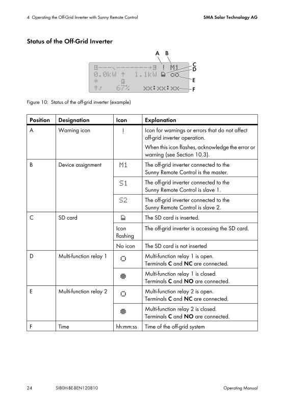
Status of the Off-Grid Inverter
Figure 10: Status of the off-grid inverter (example)
Position Designation Icon ExplanationA Warning icon Icon for warnings or errors that do not affect
off-grid inverter operation.When this icon flashes, acknowledge the error or warning (see Section 10.3).
B Device assignment The off-grid inverter connected to the Sunny Remote Control is the master.The off-grid inverter connected to the Sunny Remote Control is slave 1.The off-grid inverter connected to the Sunny Remote Control is slave 2.
C SD card The SD card is inserted.Icon flashing
The off-grid inverter is accessing the SD card.
No icon The SD card is not insertedD Multi-function relay 1 Multi-function relay 1 is open.
Terminals C and NC are connected.Multi-function relay 1 is closed. Terminals C and NO are connected.
E Multi-function relay 2 Multi-function relay 2 is open. Terminals C and NC are connected.Multi-function relay 2 is closed. Terminals C and NO are connected.
F Time hh:mm:ss Time of the off-grid system

SMA Solar Technology AG 4 Operating the Off-Grid Inverter with Sunny Remote Control
Operating Manual SI80H-BE-BEN120810 25
State of Charge of the Battery
Figure 11: State of charge of the battery in standard mode (example)
Status of the External Energy Source
Figure 12: Status of the external energy source in standard mode (example)
Position Designation ExplanationA Battery Icon for batteryB State of charge State of charge of the battery in percent
Position Designation Icon ExplanationA Active limit of the
external energy sourceElectrical limits for the electricity grid are active.
Electrical limits for the electricity grid are not active.Electrical limits for the generator are active.

4 Operating the Off-Grid Inverter with Sunny Remote Control SMA Solar Technology AG
26 SI80H-BE-BEN120810 Operating Manual
B Status of the external energy source
Voltage and frequency of the external energy source are within the set limits.Voltage and frequency of the external energy source are outside the set limits.The maximum reverse power to the external energy source has been exceeded.BatteryGenerator has been requested due to state of charge.CycleGenerator has been requested based on time.ExternGenerator has been requested by an extension cluster.LoadGenerator has been requested due to load.StartGenerator has been started manually via the off-grid inverter.TimeGenerator has been started for one hour via the off-grid inverter.
C Power of the external energy source
‒ Power of the external energy source in kW
D External energy source Icon for external energy source
E Internal transfer relays The external energy source is disconnected from the stand-alone grid.The stand-alone grid is synchronised to the external energy source. The external energy source is supplying the loads and charging the battery.
Position Designation Icon Explanation
SMA Solar Technology AG 4 Operating the Off-Grid Inverter with Sunny Remote Control
Operating Manual SI80H-BE-BEN120810 27
4.3 User Mode
4.3.1 Display Pages for OperationUser mode will display all information crucial for operating the off-grid system in different categories. User mode also allows for manual control of the off-grid inverter and components of the off-grid system, for example starting the generator.User mode distinguishes between display pages and setting pages. Display pages show the parameters of a category. To configure and operate the off-grid system, switch to a setting page.
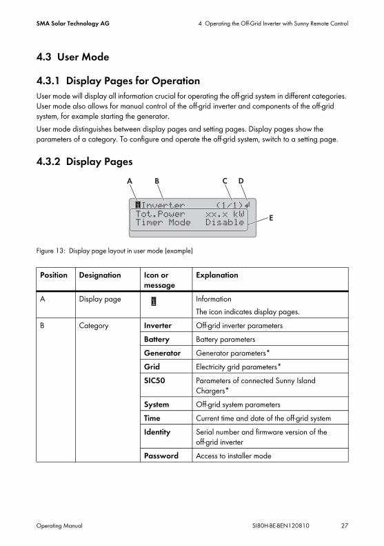
4.3.2 Display Pages
Figure 13: Display page layout in user mode (example)
Position Designation Icon or message
Explanation
A Display page InformationThe icon indicates display pages.
B Category Inverter Off-grid inverter parametersBattery Battery parametersGenerator Generator parameters*Grid Electricity grid parameters*SIC50 Parameters of connected Sunny Island
Chargers*System Off-grid system parametersTime Current time and date of the off-grid systemIdentity Serial number and firmware version of the
off-grid inverterPassword Access to installer mode

4 Operating the Off-Grid Inverter with Sunny Remote Control SMA Solar Technology AG
28 SI80H-BE-BEN120810 Operating Manual
4.3.3 Setting Pages
Figure 14: Setting page layout in user mode (example)
C Page and number of pages
‒ Page and number of pages of the selected categoryA category can contain multiple display pages e.g. Battery (3/3).
D Return icon Setting pages are available for the category.
No icon No setting pages are available for the category.E Parameters ‒ Parameters with the current values
* Is only displayed if the component is part of the off-grid system.
Position Designation Icon or display
Explanation
A Setting page icon SetThe icon indicates setting pages.
B Category Inverter Restart off-grid inverter.Set time-controlled operation.
Battery Trip manual equalisation charge.Generator Start and stop generator manually or set to
automatic mode.Reset warnings.
Time Set date and time.Password Enter the installer password.
C Page and number of pages
‒ Current page and total number of pages of the selected categoryA category can contain multiple setting pages.
Position Designation Icon or message
Explanation
SMA Solar Technology AG 4 Operating the Off-Grid Inverter with Sunny Remote Control
Operating Manual SI80H-BE-BEN120810 29
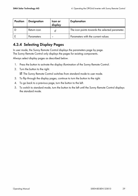
4.3.4 Selecting Display PagesIn user mode, the Sunny Remote Control displays the parameters page by page. The Sunny Remote Control only displays the pages for existing components.Always select display pages as described below.
1. Press the button to activate the display illumination of the Sunny Remote Control.2. Turn the button to the right.
☑ The Sunny Remote Control switches from standard mode to user mode.3. To flip through the display pages, continue to turn the button to the right.4. To go back to a previous page, turn the button to the left.5. To switch to standard mode, turn the button to the left until the Sunny Remote Control displays
the standard mode.
D Return icon The icon points towards the selected parameter.
E Parameters ‒ Parameters with the current values
Position Designation Icon or display
Explanation

4 Operating the Off-Grid Inverter with Sunny Remote Control SMA Solar Technology AG
30 SI80H-BE-BEN120810 Operating Manual
4.3.5 Operating and Configuring the Off-Grid InverterIn user mode, always operate the off-grid inverter as described below.
1. Select the display page for the category you want to configure.
2. Press the button. The Sunny Remote Control displays the setting pages for the display page.
3. To select the desired parameter, turn the button to the right until the return icon appears to the right of the desired parameter.☑ You have selected the parameter.
4. To set the parameter, press the button and then turn it to the left or right.
Example: Selecting the display pageYou want to restart the off-grid inverter. This setting is in the Inverter category.
• Select display page Inverter (1/1).
Example: Selecting the setting pageYou have selected the display page Inverter (1/1).
• Press the button.
☑ The Inverter (1/2) setting page appears.

SMA Solar Technology AG 4 Operating the Off-Grid Inverter with Sunny Remote Control
Operating Manual SI80H-BE-BEN120810 31
5. When you have set the required parameter, press the button. This saves the setting.
6. To exit the setting page, switch to the display page or the standard mode:• Turn the button to the left until the return icon appears in the first line.• To return to the display page, turn the button to the left until <back> appears.• To switch to standard mode, turn the button to the left until <home> appears.• Press the button.Hint: <back> and <home> also appear at the end of the list if the button is turned to the right.
Example: Setting the repetition type to Weekly in time-controlled mode
• Access the Inverter (1/2) action page.☑ The action page Inverter (1/2)
appears.
• Turn the button until the return icon appears next to the parameter Repetition. The Sunny Remote Control then changes from action page Inverter (1/2) to action page Inverter (2/2).
• Press the button.• Turn the button to the right until Weekly appears.• Press the button. This saves the parameter.
☑ The repetition type is set to Weekly in time-controlled mode.

4 Operating the Off-Grid Inverter with Sunny Remote Control SMA Solar Technology AG
32 SI80H-BE-BEN120810 Operating Manual
4.4 Installer and Expert Mode
4.4.1 Switching to Installer ModeThe installer mode is password-protected. The installer password changes constantly and must be re-calculated every time.
1. Select the setting page Password (1/1) in user mode.2. Calculate the digit sum of the operating hours Run time. This calculates the installer password.
3. Select the parameter Set and set the installer password calculated.☑ The Sunny Remote Control is in installer mode.
4.4.2 Switching to Expert ModeExpert mode can only be accessed via installer mode.
1. Switch to installer mode (see Section 4.4.1).2. Select the parameter 700.01 ActLev and set to Expert (see Section 4.4.6 "Setting the
Parameters", page 35).
Entering incorrect parameters endangers operational safety.All parameter settings which could affect the operating safety of the off-grid system are protected by the installer password.
• Only skilled persons are permitted to set and adjust system parameters.• Only give the installer password to skilled persons and operators.
Example: Calculating the digit sumOperating hours Run time is 1234 h. The digit sum is the sum of all digits:1 + 2 + 3 + 4 = 10The digit sum is 10.

SMA Solar Technology AG 4 Operating the Off-Grid Inverter with Sunny Remote Control
Operating Manual SI80H-BE-BEN120810 33
4.4.3 Menus in Installer and Expert Mode
Figure 15: Layout of the menu page in installer mode (example)
4.4.4 Parameter Page in Installer and Expert Mode
Figure 16: Layout of the parameter page in installer mode (example)
Position Designation ExplanationA Menu path The two previously selected menu levels
If you are in the top menu level, the display will show Installer in installer mode and Expert in expert mode.
B Return icon Return icon for selecting a menuC Menu ‒
Position Designation ExplanationA Menu number and
parameter number‒
B Menu path The two previously selected menu levelsC Return icon Return icon for setting the parameter
If no return icon is displayed, the parameter cannot be adjusted.D Name of the
parameter‒
E Value and unit of the parameter
‒
4 Operating the Off-Grid Inverter with Sunny Remote Control SMA Solar Technology AG
34 SI80H-BE-BEN120810 Operating Manual
4.4.5 Selecting Menus and ParametersAlways select menus and parameters as described below.
1. Switch to installer mode (see Section 4.4.1).2. Turn the button to the right until the return icon appears to the right of the required menu.
The Sunny Remote Control scrolls through the menu items on the display line by line.3. Press the button. This accesses the subordinate menu level.
☑ The Sunny Remote Control shows the subordinate menu level. The selected menu level is shown in the first line.
4. Repeat steps 2 and 3 until the Sunny Remote Control displays the first parameter page.5. Turn the button to the right until the Sunny Remote Control displays the desired parameter. 6. To exit the parameter page and go to the superordinate level or the standard mode:
• Turn the button to the left until the return icon appears in the first line.• To switch to a higher menu level, turn the button to the left until <back> appears.• To switch to standard mode, turn the button to the left until <home> appears.• Press the button.Hint: <back> and <home> also appear at the end of the list if the button is turned to the right.

SMA Solar Technology AG 4 Operating the Off-Grid Inverter with Sunny Remote Control
Operating Manual SI80H-BE-BEN120810 35
4.4.6 Setting the ParametersAlways set parameters as described below.
1. Switch to installer mode (see Section 4.4.1).2. Select the desired parameter. You can only set the
parameters for which < Set > is shown in the second line in the display.
3. Press the button.☑ The return icon flashes next to the value.✖ The display shows: Stop device to change the value?
The parameter can only be changed in standby mode.• Stop the off-grid system (see Section 5.3).
✖ The display shows: No permission to change the value.You are not allowed to change the parameter in installer mode.• If you want to change the parameters for the battery, select the New Battery menu in
the QCG (see Section 9.8 "Replacing the Battery", page 52).• If you want to change the addresses of the slaves in a cluster, select the New Clst Cfg
menu in the QCG (see Section 10.4).• For all other settings in the QCG, select the New System menu (see the installation
manual of the off-grid inverter).4. To set the parameter, turn the button to the left or right.5. Press the button.
☑ The Sunny Remote Control requests confirmation of the parameter set.
6. To confirm the value, turn the button to the right until Y flashes and then push the button.7. To discard the value, turn the button to the right until N flashes and then press the button.

4 Operating the Off-Grid Inverter with Sunny Remote Control SMA Solar Technology AG
36 SI80H-BE-BEN120810 Operating Manual
4.4.7 Directly Accessing ParametersAny parameter can be accessed directly by entering a five-digit number. The five-digit number is composed as follows:
• The first three digits are the menu number.• The last two digits are the parameter number.
1. Switch to installer mode (see Section 4.4.5).2. Select the parameter 600.02 Select Number and set the five-digit number.
☑ The parameter is displayed.✖ The display shows Item not Found?
You cannot access the parameter in installer mode.• Push the button and switch to expert mode (see Section 4.4.2).The number set is not correct.• Press the button and enter the number again.
Example: Five-digit number for direct parameter accessYou want to use parameter 111.01 TotInvPwrAt to show the entire active power of the off-grid inverter in a cluster. The five-digit number for directly accessing this parameter is 11101.
SMA Solar Technology AG 5 Starting and Stopping the Off-Grid System
Operating Manual SI80H-BE-BEN120810 37
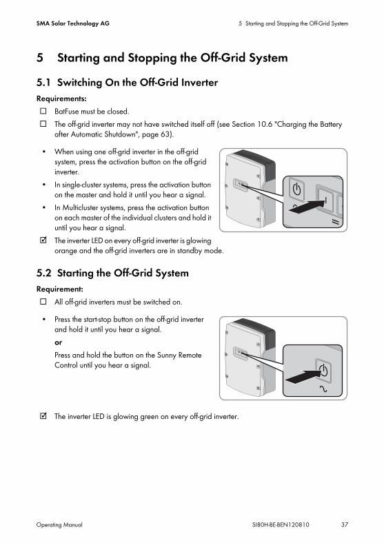
5 Starting and Stopping the Off-Grid System5.1 Switching On the Off-Grid InverterRequirements:☐ BatFuse must be closed.☐ The off-grid inverter may not have switched itself off (see Section 10.6 "Charging the Battery
after Automatic Shutdown", page 63).
• When using one off-grid inverter in the off-grid system, press the activation button on the off-grid inverter.
• In single-cluster systems, press the activation button on the master and hold it until you hear a signal.
• In Multicluster systems, press the activation button on each master of the individual clusters and hold it until you hear a signal.
☑ The inverter LED on every off-grid inverter is glowing orange and the off-grid inverters are in standby mode.
5.2 Starting the Off-Grid SystemRequirement:☐ All off-grid inverters must be switched on.
• Press the start-stop button on the off-grid inverter and hold it until you hear a signal.orPress and hold the button on the Sunny Remote Control until you hear a signal.
☑ The inverter LED is glowing green on every off-grid inverter.

5 Starting and Stopping the Off-Grid System SMA Solar Technology AG
38 SI80H-BE-BEN120810 Operating Manual
5.3 Stopping the Off-Grid SystemElectric discharge of the battery:When the off-grid inverter is stopped, it will discharge the battery via self-consumption. Hint: If the system is to be shut down for an extended period, switch off the off-grid inverter (see Section 5.4).
• Press the start-stop button on the off-grid inverter and hold it until the inverter LED is glowing orange.
or
Press and hold the button on the Sunny Remote Control until the progress bar expires.orPress the deactivation button briefly.
☑ The inverter LED is glowing orange on every off-grid inverter. The off-grid inverters are in standby mode. Time-controlled inverter operation is automatically deactivated and you must reactivate if required (see Section 5.6 "Setting Time-Controlled Inverter Operation", page 40).
What happens when you hold down the deactivation button?When you hold down the deactivation button, you trip an emergency disconnection. This triggers the uncontrolled shutdown of the off-grid system, and unsaved data is lost.
• It is better to switch off the off-grid system with the start-stop button or the Sunny Remote Control.

SMA Solar Technology AG 5 Starting and Stopping the Off-Grid System
Operating Manual SI80H-BE-BEN120810 39
5.4 Switching the Off-Grid Inverters OffRequirement:☐ The off-grid system is stopped.• Press the deactivation button on the off-grid inverter
and hold it until you hear a signal.
☑ None of the inverter LEDs on the off-grid inverters are glowing.
5.5 Tripping the Emergency Disconnection of the Off-Grid System
• Press the deactivation button on the off-grid inverter and hold it until you hear a signal.
Effects of an emergency disconnectionEmergency disconnection triggers the uncontrolled shutdown of the off-grid system and unsaved data is lost.
• Only use emergency disconnection to avoid danger or consequential damage.

5 Starting and Stopping the Off-Grid System SMA Solar Technology AG
40 SI80H-BE-BEN120810 Operating Manual
5.6 Setting Time-Controlled Inverter Operation
Requirement:☐ The Sunny Remote Control must be in user mode (see Section 4.3).
1. Select the Inverter display page and press the button.
☑ The Sunny Remote Control switches to the Inverter setting page.
2. Setting time-controlled inverter operation:• Select the Start Date parameter and set it to the required start date.• Select the Start Time parameter and set it to the required start time.• Select the Run Time parameter and set it to the required run time.• Select the Repetition parameter and set it to the required repetition cycle.
3. To activate time-controlled inverter operation, select the Timed Start parameter and set it to Enable.
☑ Time-controlled inverter operation is activated. If the off-grid inverter has started automatically under time-control and you stop the off-grid inverter, time-controlled inverter operation is deactivated automatically.
Example: Setting parameters for time-controlled inverter operationYou want to operate the off-grid inverter in inverter mode every Sunday from 10:00 am to 6:00 pm, starting Sunday, 8 January 2012. To do so, set the off-grid inverter as follows:
• Str.Date: 08.01.2012• Start Time: 10:00:00• Run Time: 08:00:00• Repetition: Weekly

SMA Solar Technology AG 6 Saving Data and Updating Firmware
Operating Manual SI80H-BE-BEN120810 41
6 Saving Data and Updating Firmware6.1 Inserting the SD CardRequirements:☐ The SD card must be formatted as FAT-16.☐ The storage capacity of the SD card must not exceed 2 GB.☐ The SD card must only be used as a data medium for the off-grid system.
• Insert the SD card, with the slanted corner facing upwards, into the SD card slot in the Sunny Remote Control. The label on the SD card must point to the front.
6.2 Saving and Loading ParametersYou can load and save the current parameter settings in two different parameter sets on the SD card. The two parameter sets are distinguished by the Sunny Remote Control in Set1 and Set2. Every parameter set saves all settings. This makes it possible to test the settings of a new parameter set without having to delete the old parameter set. Hint: As soon as you have set up a functional off-grid system, save the parameter settings to the SD card. After saving, you can further adjust the off-grid system. If the adjustment does not lead to the desired results, reload the saved parameter set.Requirement:☐ The SD card must be inserted.
1. Switch to installer mode (see Section 4.4.1).2. To save a parameter set, select the parameter 550.01 ParaSto and set the parameter:
Value ExplanationSet 1 Save the settings in the first parameter set.Set 2 Save the settings in the second parameter set.

6 Saving Data and Updating Firmware SMA Solar Technology AG
42 SI80H-BE-BEN120810 Operating Manual
3. Proceed as follows to load a parameter set:• Switch to expert mode (see Section 4.4.2).• Select the parameter 550.02 ParaLod and set the parameter:
6.3 Saving the Event History and Error HistoryRequirement:☐ The SD card must be inserted.
1. Switch to installer mode (see Section 4.4.5).2. To save the event history, select the parameter 550.03 CardFunc and set it to StoEvtHis.3. To save the error history, select the parameter 550.03 CardFunc and set it to StoFailHis.
6.4 Updating the FirmwareA firmware update will not change any settings of the off-grid inverter. If the firmware update contains new parameters, the new parameters will be set up with default values.Requirements:☐ A computer with Internet connection is required.☐ The SD card must be readable and writable with a computer.☐ The Sunny Remote Control must be connected to the master.1. To save the current parameters, save the parameter set to the SD card:
• Insert an SD card without the new firmware version.• Save the parameter set to the SD card (see Section 6.2).• Remove the SD card.
2. Use a computer to download the latest firmware (see www.SMA-Solar.com for the installation file).
3. Copy the current firmware from the computer to the main directory of the SD card.4. Stop the off-grid system (see Section 5.3).5. Insert the SD card into the SD card slot in the Sunny Remote Control.
☑ The Sunny Remote Control updates the firmware and performs a restart. In a cluster, the slaves are automatically updated by the master.
6. For a Multicluster system, repeat Step 5 for each master.7. Start the off-grid system (see Section 5.2).
Value ExplanationSet 1 Loads the settings from the first parameter setSet 2 Loads the settings from the second parameter setFactory Loads the factory settings

SMA Solar Technology AG 6 Saving Data and Updating Firmware
Operating Manual SI80H-BE-BEN120810 43
6.5 Displaying the Status of the SD Card1. Switch to installer mode (see Section 4.4.1).2. Select the parameter 312.08 CardStt and read off (see parameter document of the off-grid
inverter).
6.6 Removing the SD CardIf the SD card is removed without preparation, the removal will cause data loss. The maximum possible data loss will affect the data logged during the last 15 minutes. Always remove the SD card according to the following procedure.
1. Switch to installer mode (see Section 4.4.1).2. Select the parameter 550.03 CardFunc and set it to ForcedWrite. Unsaved data will now be
saved to the SD card.3. Remove the SD card.
6.7 Displaying the Content of the Files
Figure 17: Content of an SD card (example)
The files saved to the SD card depend on the configuration and the off-grid system.Explanation of the files:
File name Explanationevthis.log Event historyerrhis.log Error historysi010112.evt Event and error history for one day
The date (ddmmyy) is part of the file name.si010112.log Data recording for the day
The date (ddmmyy) is part of the file name.sipar1.lst Parameter set 1sipar2.lst Parameter set 2update.bin Firmware version of the off-grid inverterbatstat.txt Statistical values of the battery
These values are saved every night at 10:00 p.m.

6 Saving Data and Updating Firmware SMA Solar Technology AG
44 SI80H-BE-BEN120810 Operating Manual
Structure of the files:The files are CSV files, which means that the data is saved as text. The files are structured as follows:
• The first lines in the file are used for information. Information lines start and end with the character #.
• The data in the following lines is separated by semicolons.• Decimal places are separated by full stops.• The date format is dd/mm/yyyy.• The time format is hh:mm:ss.• Some of the parameter values are saved with plain text numbers (see the technical description
of the off-grid inverter for an explanation of the plain text numbers).Requirements:☐ A computer with installed spreadsheet software must be available.☐ The spreadsheet software must be able to read CSV files.
1. Insert the SD card into the card reader and show the content.2. Start the spreadsheet software and import the required file. Set the import filter in accordance
with the file structure (see spreadsheet software manual).
batstat.sma Statistic values of the battery for evaluation by SMA Solar Technology AGsim.ccf System information of the off-grid inverterbootex.log File generated by the operating system of the computer
This file is not generated by every operating system.
File name Explanation
SMA Solar Technology AG 7 Manually Controlling the Generator
Operating Manual SI80H-BE-BEN120810 45
7 Manually Controlling the Generator7.1 Starting the Generator with Sunny Remote ControlRequirements:☐ The off-grid inverter must be able to control the generator via a control cable.☐ The Sunny Remote Control must be in standard mode or user mode.
1. Select the Generator display page on the Sunny Remote Control and push the button (see Section 4.3.5 "Operating and Configuring the Off-Grid Inverter", page 30).
2. To start the generator and run it continuously, select the Mode parameter and set to Start.☑ The generator starts and runs until you stop it again.
3. To start the generator and run it for one hour, select the Mode parameter and set to Run1h.☑ The generator starts. If there is no generator request after one hour, the off-grid inverter stops
the generator.
7.2 Stopping the Generator with Sunny Remote Control
Requirements:☐ The off-grid inverter must be able to control the generator via a control cable.☐ The Sunny Remote Control must be in standard mode or user mode.
1. Select the Generator display page on the Sunny Remote Control and push the button (see Section 4.3.5 "Operating and Configuring the Off-Grid Inverter", page 30).
2. Select the Mode parameter and set it to Stop.☑ The generator is momentarily stopped. The generator restarts when a generator request is
issued in automatic generator mode and the minimum stop time elapses.3. To stop the generator permanently, deactivate the automatic generator mode:
• Switch to installer mode (see Section 4.4.1).• Select the parameter 235.01 GnAutoEna and set to Disable.☑ The generator is stopped permanently.
Risk of crushing injuries due to movable generator parts If the generator is stopped, the off-grid inverter can automatically restart the generator.
• Before performing work on the generator, permanently stop the generator and secure it against inadvertent restarting.
• Work on the generator in accordance with the manufacturer's specifications.

7 Manually Controlling the Generator SMA Solar Technology AG
46 SI80H-BE-BEN120810 Operating Manual
7.3 Starting the Generator without Autostart FunctionRequirement:☐ The generator is not controlled with GenMan.
1. Start the generator (see manufacturer's instructions).2. Close the switch-disconnector between generator and off-grid inverter.☑ After the warm-up period, the off-grid inverter switches the stand-alone grid to the generator.
7.4 Stopping the Generator without Autostart FunctionRequirement:☐ The generator is not controlled with GenMan.
1. Open the switch-disconnector between the generator and off-grid inverter. That prevents the generator being driven by AC sources in the stand-alone grid.
2. Stop the generator (see manufacturer's instructions).☑ The generator is stopped. After the cool-down time and the minimum stop time, you can use the
generator as an external energy source again.

SMA Solar Technology AG 8 Disconnecting the Off-Grid Inverter from Voltage Sources
Operating Manual SI80H-BE-BEN120810 47
8 Disconnecting the Off-Grid Inverter from Voltage Sources
1. Switch off the off-grid system (see Section 5.4).2. Disconnect the miniature circuit-breaker and the switch-disconnectors in the sub-distributions and
secure against reconnection.3. Open the switch-disconnector of the BatFuse and secure against reconnection.
6. If you are a skilled person, loosen all the screws of the enclosure lid and remove the lid.7. Ensure that the DC terminal is disconnected from voltage sources.8. Ensure that the terminals AC1 Loads/SunnyBoys and AC2 Gen/Grid are disconnected from
voltage sources.9. Earth and short-circuit the AC conductors.
10. Cover or safeguard any adjacent live components.
4.Danger to life due to high voltages
• If you are not a skilled person, inform a skilled person.• Steps 5 to 10 may only be performed by skilled persons.
5.Electrostatic discharges can damage the off-grid inverter.The components inside the inverter can be destroyed by electrostatic discharge.
• Earth yourself before touching any components.

9 Cleaning and Maintenance SMA Solar Technology AG
48 SI80H-BE-BEN120810 Operating Manual
9 Cleaning and Maintenance9.1 Cleaning the Enclosure of the Off-Grid Inverter
• If the enclosure is heavily soiled, use a soft brush to remove the soiling.• If the enclosure is dusty, remove the dust with a soft cloth. Do not use solvents, abrasives or
corrosive liquids.
9.2 Cleaning the Sunny Remote Control• Clean the Sunny Remote Control with a soft cloth. Do not use solvents, abrasives or corrosive
liquids.
9.3 Performing a Manual Equalisation ChargePerform a manual equalisation charge at least once a year. After extended periods without charging (e.g. systems operated seasonally), perform a manual equalisation charge at the end or start of the season.Requirement:☐ The Sunny Remote Control must be in standard mode or user mode.
1. Select the Battery display page on the Sunny Remote Control and press the button (see Section 4.3.5 "Operating and Configuring the Off-Grid Inverter", page 30).
2. Select the Equalize parameter and set to Start.

SMA Solar Technology AG 9 Cleaning and Maintenance
Operating Manual SI80H-BE-BEN120810 49
9.4 Checking the FunctionRequirement:☐ The Sunny Remote Control must be connected to the off-grid inverter/master.
• For the first six months after installation of new off-grid systems, check every week whether error messages have been registered. TThis will reveal any hidden errors in the installation or configuration:• Switch to installer mode (see Section 4.4.1).• Select the 420# Error history menu and check whether error messages have been
registered.• If error messages have been registered, rectify the cause
(see Section 10 "Troubleshooting", page 54).• Check every six months whether error messages have been registered:
• Switch to installer mode (see Section 4.4.1).• Select the 420# Error history menu and check whether error messages have been
registered.• If error messages have been registered, rectify the cause (see the technical description of the
off-grid inverter for the causes of errors and disturbances).
9.5 Checking the Connections
1. Disconnect the off-grid inverter from voltage sources (see Section 8).2. Ensure that the cables on the DC+ and DC- terminals are securely fastened
(torque: 4 Nm ... 5.7 Nm).3. Ensure that the terminals are free of corrosion.4. Ensure that the cables in the AC1 and AC2 terminals are securely fastened.5. Close the inverter (see the off-grid inverter installation manual).6. Switch on all switch-disconnectors and miniature circuit-breakers.
Danger to life due to high voltages• Connections may only be checked by skilled persons.

9 Cleaning and Maintenance SMA Solar Technology AG
50 SI80H-BE-BEN120810 Operating Manual
9.6 Checking and Maintaining the Battery
1. Stop the off-grid system and switch off the off-grid inverter (see Section 5).2. Open the switch-disconnector of the BatFuse and secure against reconnection.3. Check and maintain the battery (see the instructions of the battery manufacturer).4. Quickly connect the switch-disconnector of the BatFuse and close the BatFuse
(see the installation manual of the BatFuse).5. Start the off-grid system.
9.7 Cleaning the FansIf the Sunny Remote Control shows warning W137, W138 or W139, one of the fans is probably defective or blocked. Always use the following procedure to check and clean each fan on the affected off-grid inverter.
1. Disconnect the off-grid inverter from voltage sources (see Section 8).2. Wait for the fans to stop rotating.
Risk of injury by corrosive and/or toxic electrolyte from the batteryIf handled inappropriately, electrolyte from the battery can burn the skin or eyes or be toxic.
• Protect the battery enclosure against destruction.• Do not open or deform the battery.• Whenever working on the battery, wear rubber gloves, rubber boots and goggles.• Rinse acid splashes with clear water and consult a doctor.
Risk of burns from short-circuit currentsShort-circuit currents in the battery can cause heat build-up and electric arcs.
• Remove watches, rings and other metal objects.• Use insulated tools to mount and install the battery.• Do not place tools or metal parts on the battery.
Battery Checks and MaintenanceOnly skilled persons are suitably qualified to check and maintain the batteries.
• If you are not a skilled person, have a skilled person perform the work.
SMA Solar Technology AG 9 Cleaning and Maintenance
Operating Manual SI80H-BE-BEN120810 51
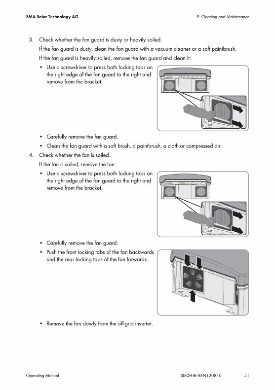
3. Check whether the fan guard is dusty or heavily soiled.If the fan guard is dusty, clean the fan guard with a vacuum cleaner or a soft paintbrush. If the fan guard is heavily soiled, remove the fan guard and clean it:• Use a screwdriver to press both locking tabs on
the right edge of the fan guard to the right and remove from the bracket.
• Carefully remove the fan guard.• Clean the fan guard with a soft brush, a paintbrush, a cloth or compressed air.
4. Check whether the fan is soiled.If the fan is soiled, remove the fan:• Use a screwdriver to press both locking tabs on
the right edge of the fan guard to the right and remove from the bracket.
• Carefully remove the fan guard.• Push the front locking tabs of the fan backwards
and the rear locking tabs of the fan forwards.
• Remove the fan slowly from the off-grid inverter.

9 Cleaning and Maintenance SMA Solar Technology AG
52 SI80H-BE-BEN120810 Operating Manual
• Release and remove the fan plug.
6. Insert the plug of the fan into the socket until it clicks into place.7. Insert the fan into the off-grid inverter until the fan clicks audibly into place.8. Push the fan guard into the retainer until it audibly clicks into place.
9.8 Replacing the Battery
5.Damage to the fan due to compressed air
• Clean the fan with a soft brush, a paintbrush, or a damp cloth.
Risk of injury by corrosive and/or toxic electrolyte from the batteryIf handled inappropriately, electrolyte from the battery can burn the skin or eyes or be toxic.
• Protect the battery enclosure against destruction.• Do not open or deform the batteries.• Whenever working on the battery, wear rubber gloves, rubber boots and goggles.• Rinse acid splashes with clear water and consult a doctor.
Risk of burns from short-circuit currentsShort-circuit currents in the battery can cause heat build-up and electric arcs.
• Remove watches, rings and other metal objects.• Use insulated tools to mount and install the battery.• Do not place tools or metal parts on the battery.

SMA Solar Technology AG 9 Cleaning and Maintenance
Operating Manual SI80H-BE-BEN120810 53
1. Stop the off-grid system and switch off the off-grid inverter (see Section 5).2. Open the switch-disconnector of the BatFuse and secure against reconnection.3. Disassemble the battery to be replaced (see battery manufacturer's instructions).4. Mount and connect the new battery (see battery manufacturer's instructions). The battery must
comply with the technical requirements of the off-grid inverter (see the off-grid inverter installation manual for technical data of the DC connection).
5. Quickly connect the switch-disconnector of the BatFuse and close the BatFuse (see the installation manual of the BatFuse).
6. Switch on the off-grid inverter (see Section 5.1).☑ If the Sunny Remote Control shows <Init System> , press and hold the button until the
Sunny Remote Control shows the QCG.7. Select the New Battery menu and push the button.8. Confirm with Y. 9. Select the BatTyp parameter, set the battery type and confirm with Y.
10. Select the BatVtgLst parameter, set the battery voltage and confirm with Y.11. Select the BatCpyNom parameter, set the C10 capacity of the battery (see the installation
manual of the off-grid inverter on how to calculate the battery capacity) and confirm the battery capacity with Y.
12. Select the last page and confirm the question Setup New Battery with Y.
Installation work on the batteryOnly skilled persons have the qualifications required to perform installation work on batteries.
• If you are not a skilled person, have a skilled person perform the work.

10 Troubleshooting SMA Solar Technology AG
54 SI80H-BE-BEN120810 Operating Manual
10 Troubleshooting10.1 What to Do if an Error OccursDisplay of Errors, Warnings and EventsPending warnings and errors are shown automatically on the display of the Sunny Remote Control until the cause of the warning or error is no longer recorded by the off-grid inverter or is acknowledged. Events are recorded by the off-grid inverter. The following menus record warnings, errors and events:
• 410# Error activeDisplay of currently pending warnings and errors
• 420# Error historyError and warning history
• 430# Event historyHistory of events
Error LevelsThe off-grid inverter distinguishes between five separate error levels, with each resulting in a different behaviour.Level Designation Display on the
Sunny Remote Control
Explanation
1 Warning Warning Warning, inverter continues running. Information in standard mode indicating that a warning has been generated.
2 Disturbance 1 Malfunction Disturbance that is only detectable during operation. The off-grid inverter shuts down. Restart can be initiated immediately (e.g. via autostart).
3 Disturbance 2 Malfunction Disturbance that is also detectable in standby mode. The off-grid inverter shuts down. Restart is blocked until the disturbance is no longer detected by the off-grid inverter.
4 Failure Failure Device failure, the off-grid inverter shuts down. Troubleshooting, acknowledgment of the error and manual restart necessary.
5 Device defect Defect The off-grid inverter is defective and shuts down. The off-grid inverter must be replaced.

SMA Solar Technology AG 10 Troubleshooting
Operating Manual SI80H-BE-BEN120810 55
Treatment of Pending Errors upon ActivationDuring the activation procedure, all pending errors are generally acknowledged without an entry being made in the history. Errors which are still pending are entered again after activation. Errors which are detected by the off-grid inverter before activation, and are no longer detected after activation, are shown in list 420# Error history.
AutostartThe autostart function allows automatic restarts in the event of disturbances. If the autostart function fails in the event of a disturbance, the off-grid inverter attempts to carry out the next autostart immediately. The number of autostarts is restricted. If the off-grid inverter runs in inverter operation without disturbances for ten minutes, it resets the autostart counter.When the maximum number of autostarts has been reached, the off-grid inverter reacts as follows:
• The off-grid inverter waits ten minutes.• The autostart counter is reset.• The off-grid inverter attempts to perform an autostart.• When the maximum number of autostarts is reached, the off-grid inverter waits ten minutes.
Master-Slave TreatmentThe 250.30 RnMod parameter influences the reactions of a three-phase off-grid system in the event of a disturbance. Depending on the setting, the entire cluster may either stop or remain in if an error in a slave cannot be rectified via the autostart function, the entire cluster may either stop or remain in in operation without the affected slave. In the default setting, the cluster remains in operation.Each off-grid inverter records and saves its own errors. The slaves report their errors to the master. The master collects these error messages and records the errors of the slaves as warnings in its menu 410# Error active. If you acknowledge the error of the slave on the master, the master sends the acknowledgement to the slave.The error and event memories of the master and the slaves are not synchronised. If the off-grid system is restarted, the errors of the slaves are acknowledged.
Example: Handling errors in a clusterSlave 1 reduces its power due to excessive temperature and records warning W138 in its menu 410# Error active. Slave 1 reports the warning to the master. The master records the warning in its menu 410# Error active.

10 Troubleshooting SMA Solar Technology AG
56 SI80H-BE-BEN120810 Operating Manual
10.2 Acknowledging a Generator ErrorRequirement:☐ The Sunny Remote Control must be in standard mode or user mode.
1. Rectify the cause for the disconnection of the generator from the stand-alone grid (see the technical description of the off-grid inverter for causes of errors and disturbances).
2. Select the Generator display page on the Sunny Remote Control and push the button (see Section 4.3.5 "Operating and Configuring the Off-Grid Inverter", page 30).
3. Set the Error parameter to Ackn.
10.3 Acknowledging Level 3 and 4 ErrorsIf a disturbance or failure has occurred, the off-grid inverter switches to standby mode.
1. Rectify the cause (see the technical description of the off-grid inverter for the causes of errors and disturbances).
2. Push the button on the Sunny Remote Control. This acknowledges the error.3. Start the off-grid system (see Section 5.2).
10.4 Changing Slave Addresses in a ClusterIf you want to change slave addresses (e.g. after replacing an off-grid inverter), you can assign the slaves a new address using the QCG. Only the address is changed - all other configurations remain as they were, e.g. assignment of the clusters in a multicluster system. When replacing a master, you must reconfigure the cluster (see the installation manual of the off-grid inverter on the configuration of single-cluster operation or Multicluster operation).You can change the slave addresses in two ways:
• Change the slave addresses with a Sunny Remote Control.• Change the slave addresses without a Sunny Remote Control.
Changing Slave Addresses with a Sunny Remote ControlRequirements:☐ The off-grid inverters must be switched off.☐ A Sunny Remote Control is connected to the master only.
1. Switch the slave on.2. Turn on the master and then press and hold the button on the Sunny Remote Control.
☑ A signal sounds three times and the QCG starts.3. Select the NewClstCfg menu and confirm with Y.4. For a one-phase system, set 1Phs and press the button.5. For a three-phase system, set 3Phs and press the button.

SMA Solar Technology AG 10 Troubleshooting
Operating Manual SI80H-BE-BEN120810 57
6. Confirm the question Setup new cluster ? with Y.7. Wait until the inverter LED of slave 1 flashes and the Sunny Remote Control shows the message
To identify Slave1 press Tss on the Slv.8. Press the start-stop button at slave 1.
☑ The QCG configures slave 1.
• To configure slave 2, wait until the inverter LED of slave 2 flashes and the Sunny Remote Control shows the message To identify Slave2 press Tss on the Slv.
• Press the start-stop button on slave 2.☑ A signal sounds and the QCG configures slave 2.
9. Press the button. This closes the QCG.☑ The off-grid inverter switches into standard mode.
Changing the Slave Addresses Without a Sunny Remote ControlOnly use this method if no Sunny Remote Control can be connected.Requirement:☐ There is no Sunny Remote Control connected to the cluster.
1. Switch the off-grid inverters on.☑ The off-grid inverters are in standby mode.
2. Press and hold the activation button on the master until a signal sounds three times.☑ The cluster is restarted and the LEDs on the off-grid
inverters in the cluster flash.
3. In a one-phase system, press the activation button repeatedly until one LED flashes.4. In a three-phase system, push the activation button repeatedly until all three LEDs flash.

10 Troubleshooting SMA Solar Technology AG
58 SI80H-BE-BEN120810 Operating Manual
5. Wait until the LED/LEDs of all off-grid inverters flash.6. Press the start-stop button on slave 1.
☑ The master configures slave 1.
7. In order to configure slave 2, press the start-stop button on slave 2.☑ The master configures slave 2.
8. Press the start-stop button on the master. This completes configuration.
10.5 Frequently Asked Questions
10.5.1 Questions on the Off-Grid InverterError F117 occurs when starting the off-grid inverter?
The loads connected to the stand-alone grid might be too great for the off-grid inverter.• Switch some loads off.A permanent short-circuit might exist in the stand-alone grid.• If you are a skilled person, check whether there is a short-circuit at connection AC1 and in
the stand-alone grid.
The off-grid inverter does not deactivate even though you have opened the switch-disconnector of the BatFuse?
The off-grid inverter might still be supplied from the AC side.• Switch off all AC sources and disconnect them from the off-grid inverter.
The off-grid inverter does not switch to silent mode?Another function might have a higher priority than silent mode, e.g. equalisation charge or full charge.

SMA Solar Technology AG 10 Troubleshooting
Operating Manual SI80H-BE-BEN120810 59
After automatic disconnection in battery protection mode, the off-grid inverter can no longer be started?
• Switch all loads off.• If there is a generator, start the generator manually at the generator. Observe the warm-up
time of the generator. Five minutes without charge current can result in disconnection of the off-grid inverter.
• If enough power is available from the generator or the AC sources in the stand-alone grid, e.g. sufficient solar irradiation for PV inverters, switch the off-grid inverter on. AC sources in the stand-alone grid cannot feed in electric current until the off-grid inverter has been started and is in operation.
How can I switch between winter and summer operation e.g. for alpine chalets?• Save two different parameter sets for winter and summer operation on the SD card and load
them in the appropriate season (see Section 6.2 "Saving and Loading Parameters", page 41).
10.5.2 Questions on the Sunny Remote ControlWhy is the display of the Sunny Remote Control dark and why is nothing displayed?
The off-grid inverter might not be switched on.• Switch on the off-grid inverter (see Section 5.1).✖ The off-grid inverter does not switch on?
• If you are a skilled person, ensure that the fuse in the BatFuse is not defective.The Sunny Remote Control might not be connected to the off-grid inverter.• If you are a skilled person, ensure that the Sunny Remote Control is connected to the off-grid
inverter.The RJ45 data cable might be damaged.• If you are a skilled person, replace the RJ45 data cable between the Sunny Remote Control
and the off-grid inverter.
Why is it not possible to change the parameters?The parameter might only be shown in expert mode.• Switch to expert mode (see Section 4.4.2).The parameter might only be changeable in standby mode or in the QCG.• Note the messages in the display (see Section 4.4.6 "Setting the Parameters", page 35).The parameter might be hidden as it is not required in the configuration set for the off-grid system.• Check that the configuration does not deactivate any functions which are required.

10 Troubleshooting SMA Solar Technology AG
60 SI80H-BE-BEN120810 Operating Manual
How do I start the QCG?• See the installation manual of the off-grid inverter for information on starting the QCG.
Why is "MCC operation failed" shown in the display?An action with the SD card has failed.• Ensure that the write protection on the right side of the SD card is deactivated.• Use a computer to ensure that the SD card is free of errors.• If you are a skilled person, ensure that the data cable between the Sunny Remote Control
and the off-grid inverter is undamaged and that the plugs are firmly inserted into the sockets.
Why is Incomp shown in the display?The SD card is not formatted with the FAT-16 file system.
10.5.3 Questions on the External Energy SourceThe off-grid inverter does not connect to the running generator?
A high output power of the off-grid inverter when the battery state of charge is low can prevent the off-grid inverter raising the AC voltage in the stand-alone grid to the AC voltage of the generator. The off-grid inverter cancels synchronisation.• To charge the battery, reduce the power of the loads.The generator voltage might not be within the limiting values for voltage and frequency.• Check whether the icon " " is displayed permanently in standard mode.
If the " " icon is not displayed, ensure that the fuse is not defective or the miniature circuit-breaker is activated.If the " " icon is not displayed permanently, the generator voltage is sporadically outside the limiting values.• If you are a skilled person, set the limiting values for voltage and frequency of the
generator voltage (see the installation manual of the off-grid inverter).If the " " icon is displayed permanently, the off-grid inverter is in the warm-up period or is blocked for connection. Hint: Check whether the Sunny Remote Control displays the " " warning icon in standard mode.
Is a GenMan used in the system?• If you are a skilled person, check the feedback signal at the DigIn connection.• Ensure that the generator is started manually via the GenMan only.

SMA Solar Technology AG 10 Troubleshooting
Operating Manual SI80H-BE-BEN120810 61
The off-grid inverter only connects to the generator briefly?The generator might be overloaded.• Select parameter 234.03 GnCurNom and set it to 75% of the rated current of the
generator.• If possible, reduce the power of the loads.The set maximum generator voltage permitted might be too low.• If you are a skilled person, select the 234.02 GNVtgMax parameter and set it to the
maximum generator voltage.The minimum frequency set for the generator voltage might be too high.• If you are a skilled person, select parameter 234.05 GnFrqMin and set it to the minimum
frequency of the generator voltage.The permitted time 234.14 GnRvTm for reverse power might have been exceeded.• Check whether warning W401 is registered in menu 420# Error history.
Hint: If a warning was entered, the warning icon " " is shown in the standard mode of the Sunny Remote Control.
• Select the 540.02 GnAck parameter and set to Ackn. This acknowledges the generator error.
The off-grid inverter does not connect to the external energy source, although the limiting values for voltage and frequency are now complied with?
The off-grid inverter is switched with a hysteresis, i.e. the limiting values for connection do not correspond to the limiting values for disconnection.
10.5.4 Questions on the BatteryA battery cell is defective?
• If you are a skilled person, remove the defective battery cell from the battery system. This reduces the rated voltage of the battery by the voltage of the battery cell.
• In the QCG, set the current rated voltage of the battery under New Battery (see Section 9.8 "Replacing the Battery", page 52).
The battery discharges even though the generator is running?The off-grid inverter might not be connecting to the generator.• Rectify the cause (see Section 10.5.3 "Questions on the External Energy Source", page 60).The power of the loads might exceed the power of the generator.
The state of charge of the battery is not 100% after completion of a full charge?The power requirements of the loads might have been so high before completion of the full charge that the battery could not be charged 100%.• If necessary, select the parameter 222.03 AptTmFul and set it to a longer period.

10 Troubleshooting SMA Solar Technology AG
62 SI80H-BE-BEN120810 Operating Manual
What do you need to do after replacing a battery current sensor?• If you are a skilled person, calibrate the battery current sensor (see the installation manual
of the off-grid inverter for commissioning instructions).
10.5.5 Questions on Cluster Systems and Multicluster SystemsExtension clusters remain in standby mode, although the main cluster is in inverter mode?
The data cable between the masters of the individual clusters might not be connected. The master of the main cluster cannot forward the "Start" command to the masters of the extension clusters.
Why is the Multicluster system not supplying full power?An extension cluster or individual off-grid inverters of an extension cluster might have failed.
In the Multicluster system, high powers are passed back and forth between the clusters?
The state of charge of the batteries might differ temporarily. The off-grid system equalises different states of charge automatically.The nominal frequencies and nominal voltages might be defined differently.• Set the frequencies and voltages in the 210# Inverter Settings menu to the same values
for all masters.The battery capacities might differ significantly.• If you are a skilled person, distribute the battery capacities to the clusters as evenly as
possible.Individual battery cells of a battery might have failed.• If you are a skilled person, disconnect defective battery cells and set the new rated voltage
and capacity (see Section 9.8 "Replacing the Battery", page 52).

SMA Solar Technology AG 10 Troubleshooting
Operating Manual SI80H-BE-BEN120810 63
10.6 Charging the Battery after Automatic Shutdown
When a battery is deeply discharged, the off-grid inverter shuts down automatically and you cannot restart it. In order to start the off-grid inverter again after an automatic shutdown, you must charge the battery in emergency charge mode.In emergency charge mode, the off-grid inverter does not form a separate stand-alone grid, and you can charge the battery using a generator. Battery management is active in emergency charge mode and the off-grid inverter charges the battery in accordance with the parameter settings. In standby mode or in the QCG, you can adapt the parameters for the battery, e.g. the battery nominal voltage, if a battery cell fails.
Requirement:☐ The Sunny Remote Control must be connected to the master.
Procedure:
• Connect the generator to terminal AC1.• Charge the battery.• Disconnect the generator from terminal AC1.• Start the off-grid system.
Connecting the Generator to Terminal AC11. Disconnect the off-grid inverter from voltage sources (see Section 8).2. If a generator is installed permanently in the off-grid system, bridge the terminals AC1 and AC2.3. If a mobile generator is used, connect the generator to terminal AC1 (see the installation manual
of the off-grid inverter).4. Close the off-grid inverter (see commissioning in the off-grid inverter installation manual).
Danger to life due to high AC voltagesIn order to charge the battery after automatic shutdown of the off-grid inverter, the installation of the off-grid inverter must be changed.
• Only skilled persons may charge the battery after automatic shutdown of the off-grid inverter.
Restricted management functions in emergency charge modeIn emergency charge mode, the generator management is not active. The limits for voltage, current and frequency are not monitored. Set the maximum current consumption of the off-grid inverter for charging the battery in emergency charge mode. The off-grid inverter does not record additional stress on the generator caused by loads.

10 Troubleshooting SMA Solar Technology AG
64 SI80H-BE-BEN120810 Operating Manual
Charging the Battery1. Switch off all loads.2. Activate or deactivate all miniature circuit-breakers and/or fuse-switch-disconnectors for energy
sources.3. Quickly connect the switch-disconnector of the BatFuse and close the BatFuse
(see the installation manual of the BatFuse).4. Start the generator.5. Switch the off-grid inverter on (see Section 5.1).6. If the Sunny Remote Control shows <Init System> , press and hold the button.
☑ The Sunny Remote Control shows the QCG.
7. Select menu Emerg Charge and press the button.
8. Confirm with Y.☑ The Sunny Remote Control shows the
ExtCurMax parameter.
9. Set the AC current of the connected generator and press the button.10. Confirm the AC current with Y.11. Turn the button to the right and confirm the message
Emerg. Charg Mode Start?.
SMA Solar Technology AG 10 Troubleshooting
Operating Manual SI80H-BE-BEN120810 65
Disconnecting the Generator from Terminal AC11. Switch off the off-grid inverter (see Section 5.4).2. Ensure that the generator is stopped permanently.3. Disconnect the off-grid inverter from voltage sources (see Section 8).4. If the terminals AC1 and AC2 are bridged, remove the bridge.5. If a mobile generator is used, disconnect the generator from terminal AC1.6. Close the off-grid inverter (see commissioning in the off-grid inverter installation manual).
Starting the Off-Grid System1. Switch on or connect all miniature circuit-breakers and fuse-switch-disconnectors.2. Start the off-grid system (see Section 5.2).
Interrupting emergency charge modeYou can interrupt the emergency charge mode, e.g. to add diesel to a generator.
• Press and hold the button.☑ Emergency charge mode is stopped.
• Press and hold the button.☑ Emergency charge mode is running.

11 Glossary SMA Solar Technology AG
66 SI80H-BE-BEN120810 Operating Manual
11 GlossaryAbsorption phaseSee constant voltage phase
AC couplingThe connection between various loads, generators and storage devices in the stand-alone grid.
AGM batteryAbsorbent glass mat separator battery. In AGM batteries, the electrolyte is held in a fibreglass mat. The AGM battery is a sealed lead acid battery. A gas mixture consisting of hydrogen and oxygen is always generated when lead acid batteries are charged, and in normal operation this mixture undergoes internal recombination to form water. Hence, there is no need to regularly top up the battery cells with water, which is why these batteries are often described as low maintenance or even maintenance-free batteries. AGM batteries are available from many different manufacturers for a wide range of applications. They usually have very good high-current properties but lower deep-cycle stability.
Anti-islandingAnti-islanding is a process which protects against unintentional stand-alone grid formation at the connection of the external energy source. This is required to ensure that the off-grid inverter prevents possible reverse voltage to these power supply units if the external energy source fails.
BatteryA battery is an electrochemical energy storage device that can release previously stored chemical energy as electrical energy. A distinction is made between non-rechargeable primary elements and rechargeable secondary elements (rechargeable batteries or accumulators). Lead acid batteries are generally used as rechargeable secondary elements in off-grid systems.
Battery bankSee Battery system
Battery charge modeAn off-grid inverter operating mode, in which the off-grid inverter takes energy from the AC grid to recharge the battery in a controlled way. In this operating mode, the off-grid inverter is primarily responsible for correctly charging the batteries and acts like an independent battery charging device.
SMA Solar Technology AG 11 Glossary
Operating Manual SI80H-BE-BEN120810 67
Battery cycleThe battery cycle is the cumulative total discharge current over time, measured in ampere-hours. These meters are not automatically reset after charging. The nominal battery cycle is the battery cycle relative to the nominal capacity of the batteries.
Battery inverterSee Off-grid inverter
Battery managementBattery management is responsible for optimal battery charging and reliable protection against deep discharge. This is the only way of ensuring that the battery service life corresponds to the manufacturer's specifications.
Battery power converterSee Off-grid inverter
Battery protection modeBattery protection mode protects the battery. If the battery falls below the limiting values for the state of charge, the battery protection mode is activated. To protect the battery, the off-grid inverter switches to standby mode or deactivates.
Battery systemSeries connection and possibly also parallel connection of several identical batteries. Battery banks of 12 V, 24 V, 48 V and 60 V are typical.
Boost chargeSee Fast charge
Bulk phaseSee Constant current phase
CapacityDescribes the storage capability of a cell or battery, specified in ampere-hours or watt hours. The capacity of a battery is heavily dependent on the charging cycle, the electrical current strength drawn and the temperature.
Charge modeSee Battery charge mode

11 Glossary SMA Solar Technology AG
68 SI80H-BE-BEN120810 Operating Manual
ClusterMultiple off-grid inverters which are switched in parallel on the DC side, and which are connected to a shared battery system. On the AC output side, these inverters can form a single-phase or three-phase stand-alone grid. The inverters in a cluster must be connected via data cables and configured in such way that one inverter manages the cluster as a master and all other devices communicate with the master as slaves.
Constant current phaseCharging phase in which the battery can be charged using the maximum charging current.
Constant V phaseSee Constant voltage phase
Constant voltage phaseA charging phase using constant charging voltage to charge the battery. The charging current constantly decreases in this phase.
C rateThe nominal capacity specification is always provided with the discharge time on which the capacity is based. The nominal capacity is the product of the constant charging current IN and the discharge time tN, which passes between commencement of discharging the fully charged battery and when the final discharge voltage US is reached. For stationary batteries, the C10 capacity is usually specified. A battery with a capacity of C10 = 200 Ah can be discharged for 10 hours at a nominal current of 0.1 × C10 = I10 = 20 A.
DeratingA controlled power reduction, usually dependent on component temperatures. Compared with the practice of completely shutting down the device, the effect on the stand-alone grid is smaller with derating.
ElectrolyteAllows the conduction of ions within a battery. The electrolyte in lead acid batteries is diluted sulphuric acid.
Equalise chargeSee Equalisation charge

SMA Solar Technology AG 11 Glossary
Operating Manual SI80H-BE-BEN120810 69
Equalisation chargeEqualisation charge is a charge process in the constant voltage phase. Equalisation charges charge different series-connected battery cells to a uniform state of charge of 95% … 100%. Without regular equalisation charging, the states of charge of the individual cells slowly drift apart, which can lead to premature battery system failure.
Extension clusterAn extension cluster is a cluster within the Multicluster system which is subordinate to the main cluster. The master of the extension cluster obeys the instructions issued by the master of the main cluster. The master of the extension cluster sends the operating data of its cluster to the master of the main cluster. If the master of an extension cluster stops, only this cluster stops working. In this case, the Multicluster system continues to operate with reduced power.
Fast chargeFast charge is a charging process in the constant voltage phase. Fast charging charges the battery as quickly and efficiently as possible to a state of charge of approx. 85% … 90%.
FirmwareFirmware is software embedded in electronic devices. Firmware is stored in a non-volatile, electronic memory module.
Float chargeIn a float charge, the off-grid inverter attempts to maintain the battery at a high state of charge by using a lower charge voltage. Float charge is more important for grid backup systems and less important for off-grid systems.
Full chargeFull charge is a charging process in the constant voltage phase. Full charge charges the battery to approx. 95% at least once a month. This avoids premature battery aging caused by inadequate charging.
GeneratorAn electric generator is an electrical machine which converts kinetic energy into electrical energy. In off-grid systems, not only the electric generator itself, but also the combustion unit (diesel, petrol, or gas motor) necessary for the power unit are simply referred to jointly as generator.
Grid-tie plantPV plant which is connected to the electricity grid.

11 Glossary SMA Solar Technology AG
70 SI80H-BE-BEN120810 Operating Manual
Inverter modeOperating mode of the off-grid inverter in which the off-grid inverter supplies the stand-alone grid from the energy in the battery. In this operating mode, the off-grid inverter is primarily responsible for the control of frequency and voltage in the stand-alone grid.
I-PhaseSee Constant current phase
Main clusterThe main cluster is the leading cluster within a Multicluster system. The master of the main cluster is the central user interface for the main cluster and all extension clusters of a stand-alone grid. The master of the main cluster is superior to the masters of the extension cluster. The following are some of the tasks performed by the master of the main cluster:
• Starting and stopping the Multicluster system• Controlling and monitoring the masters of the extension cluster• Communicating with the Multicluster Box
If the master of the main cluster stops operation, the entire Multicluster system shuts down. If a generator is integrated in the stand-alone grid, it will take over the power supply to the loads in this case.
MasterA configuration setting which assigns the leading role in a cluster to an off-grid inverter or backup inverter. The master performs centralised control and monitoring tasks (e.g., frequency regulation, battery management, generator control, and control of the Automatic Switch Box in the backup system), which must be performed by just one device in a cluster. All other inverters in the cluster must be configured to leave these tasks to the master, and to be controlled by the master (see Slave). The master is also the device used to configure and operate the cluster, and record data centrally.
Multicluster BoxThe Multicluster Box is the AC main distribution in the Multicluster system and a component of the SMA Multicluster Technology. In a stand-alone grid the Multicluster Box connects the clusters with the loads, the AC sources of the stand-alone grid, and the generator.
Multicluster systemA Multicluster system is made up of multiple clusters connected in parallel. The power of the Multicluster system increases with the number of clusters. The clusters are connected in parallel via a Multicluster Box. The size of the Multicluster Box is determined when the system is designed depending on the power requirement.

SMA Solar Technology AG 11 Glossary
Operating Manual SI80H-BE-BEN120810 71
Off-grid inverterA bidirectional converter capable of regulating voltage and frequency in a stand-alone grid as well as correctly charging the batteries. The off-grid inverter forms a stand-alone grid and maintains a stable and autonomous energy supply by regulating all processes.
Off-grid system
An off-grid system is the entire system with all components required to implement a stand-alone grid. Batteries are a major component of off-grid systems used for energy storage. In order to increase the availability of the stand-alone grid and to reduce the battery capacity, the off-grid system can use external energy sources as an energy reserve.
Overload capacityThe overload capacity of an inverter is the short-term power which the inverter is capable of maintaining for a few minutes or seconds. The overload capacity is significantly above the rated power in off-grid inverters. Overload capacity is important to be able to start electrical machines with a rated power close to the rated power of the off-grid inverter, as these machines typically require six times the rated current (in relation to the nominal current) when starting.
Parallel connectionParallel connection of batteries increases the capacity of the battery system while the voltage remains constant. Example: Two 24 V/100 Ah batteries connected in parallel still have a voltage of 24 V, but a capacity of 100 Ah + 100 Ah = 200 Ah.
Piggy-Back (board)A printed circuit board plugged into another printed circuit board to enable optional functions. A Piggy-Back board can also replace an individual chip. In this case, the chip is removed and the board is plugged into the empty base.
PV arrayTechnical device for the conversion of solar energy into electrical energy. All electrically connected (in series and in parallel) PV modules of a PV plant are referred to a PV array.
PV inverterDevice for converting the direct current supplied by the PV array into grid-compliant alternating current. Inverters for PV plants usually include at least one MPP tracker, store operating data, and monitor the power supply line of the PV plant.
PV moduleElectrical connection of several PV cells encapsulated in an enclosure to protect the sensitive cells from mechanical stress and environmental effects.

11 Glossary SMA Solar Technology AG
72 SI80H-BE-BEN120810 Operating Manual
PV plantTerm for a solar energy system for power generation. This includes all components needed for collecting and utilising solar energy. In the case of grid-tie plants, this includes the PV array as well as the PV inverter.
Quick Configuration GuideThe Quick Configuration Guide (QCG) is used to configure the settings required for operation. Step by step, the QCG prompts you to make the settings required for the off-grid system. Parameters for a cluster are set centrally at the master. All slaves take on the configuration automatically.
Sealed lead acid batteryBattery type where the electrolyte is bound in a gel. This is a type of closed lead acid battery. A hydrogen and oxygen gas mixture is always generated when lead acid batteries are charged, and in normal operation this mixture undergoes internal recombination to form water. Hence, there is no need to regularly top up water, which is why these batteries are often described as low maintenance or even maintenance-free batteries (see also AGM batteries). There are sealed lead acid batteries for high-current applications but also for cycle operation with very high cycle resistance.
Search modeSearch mode is an energy saving mode. At regular intervals, the off-grid inverter checks whether loads are connected to the system. If the off-grid inverter does not detect any loads, the off-grid inverter switches to search mode. Once a load is connected, the off-grid inverter exits search mode and switches to normal operation.
Self-dischargeCharge loss of a battery cell while it is stored or unused. A higher ambient temperature has a strong influence on self-discharge.
Series connectionThe positive pole of each battery is connected to the negative pole of the next battery. There is only one circuit where current can flow. Series connection increases the voltage of the battery system. If two 24 V batteries with a capacity of 100 Ah each are connected in series, the total voltage is 24 V + 24 V = 48 V, while the total capacity remains at 100 Ah.
Silent modeSilent mode is an energy saving mode for grid backup systems. If a configurable time for the float charge has expired, the off-grid inverter switches to standby mode. The off-grid inverter is then in standby mode. If the electricity grid fails when in standby, the off-grid inverter provides a stand-alone grid within seconds.

SMA Solar Technology AG 11 Glossary
Operating Manual SI80H-BE-BEN120810 73
SlaveA configuration setting which assigns a subordinate role in a cluster to an off-grid or backup inverter. Thus, this device is relieved of control and monitoring tasks, which must (or may) only be performed by the master in a cluster. Slave devices accept the configuration settings, current firmware, and start/stop commands from the master, and report events, warnings and error messages.
Sleep modeSleep mode is an energy saving mode in single-phase parallel off-grid systems. If the power of the loads does not require the power of all off-grid inverters, the master switches off one or two slaves.
Stand-alone gridA stand-alone grid is an electricity grid which is independent of the public energy supply. A stand-alone grid with an off-grid inverter is designed as a single-phase or three-phase AC grid and integrates various kinds of power generators such as PV plants and small wind turbine systems.
State of chargeDescribes the current amount of charge that can be drawn from the battery, in percent of the nominal capacity. If 25 Ah is taken from a 100 Ah battery, for example, the state of charge (SOC) is then 75%.
Wind power inverterDevice for converting the direct current from the wind energy generator to grid-compliant alternating current.

12 Contact SMA Solar Technology AG
74 SI80H-BE-BEN120810 Operating Manual
12 ContactIf you have technical problems concerning our products, please contact the SMA Service Line. We require the following information in order to provide you with the necessary assistance:
• Off-grid inverter type• Serial number of the off-grid inverter• Firmware version of the off-grid inverter• Error message indicated• Type of battery connected• Nominal battery capacity• Nominal battery voltage• Type of communication products connected• Type and size of additional energy sources• If a generator is connected:
– Type– Power– Maximum current
SMA Solar Technology AG Sonnenallee 134266 Niestetal, Germanywww.SMA.de
SMA Serviceline Tel. +49 561 9522 399Fax: +49 561 9522 4697E‑Mail: [email protected]

SMA Solar Technology AG Legal Restrictions
Operating Manual SI80H-BE-BEN120810 75
The information contained in this document is the property of SMA Solar Technology AG. Publishing its content, either partially or in full, requires the written permission of SMA Solar Technology AG. Any internal company copying of the document for the purposes of evaluating the product or its correct implementation is allowed and does not require permission.
SMA Factory WarrantyThe current guarantee conditions come enclosed with your device. These are also available online at www.SMA.de and can be downloaded or are available on paper from the usual sales channels if required.
TrademarksAll trademarks are recognized even if these are not marked separately. Missing designations do not mean that a product or brand is not a registered trademark.The Bluetooth® word mark and logos are registered trademarks owned by Bluetooth SIG, Inc. and any use of such marks by SMA Solar Technology AG is under licence.SMA Solar Technology AGSonnenallee 134266 NiestetalGermanyTel. +49 561 9522-0Fax +49 561 9522-100www.SMA.deE-Mail: [email protected]© 2004 to 2012 SMA Solar Technology AG. All rights reserved
