sunsetter - the home depot · congratulations! you have just purchased america’s # 1 retractable...
TRANSCRIPT

OWNER’S MANUAL& INSTALLATIONINSTRUCTIONS
SunSetter
VISTA® andMotorized Awnings
WARNING:Failure to follow these
instructions could result inPERSONAL INJURY!

Congratulations! You have just purchased America’s # 1 Retractable Awning. The SunSetter lateralarm awning will provide you and your family with many years of enjoyment on your deck or patio.
Before you begin installation, take a moment to familiarize yourself with the awning and your Owner’sManual. Please check to insure all of the parts listed on page 4 have been included with your awningand that you have the correct size, color and model awning.
Installation of your AwningNote: Your awning has been shipped to you fully assembled but, it is important to follow this instructionmanual to securely fasten the mounting brackets to your home and install the awning. Please read theseinstructions completely before installing your SunSetter awning.Left and Right references are as you are facing the house. You have been provided with the proper fas-teners for mounting to your wall surface either wood lag screws or masonry bolts.
For the greatest enjoyment of your lateral arm awning, please mount as high on your wall as possible,with a recommended mounting height of 9’. If your awning is a motorized model, your electrical cordwill allow you 12’ to reach your GFI outlet and you will find your remote attached to the cord. If you willbe installing a protective cover, do so after Step 15 on page 9. If you are installing on a soffit, seeAppendix C on page 16.
Operation of your AwningYour SunSetter Awning, once installed, has the ability to be opened partially or to its full projection tosuit your deck or patio design. The pitch of your awning may be easily adjusted, up or down, from thefactory setting based upon your actual mounting height. Please see Appendix A on page 13, if youwould like to make this adjustment.
Please retain your Owner’s Manual and Installation Instructions for future reference regarding operation,care and maintenance, troubleshooting, customer service and warranty information.
Customer SupportOur technical experts are available from 8am - 10pm EST daily via email at [email protected] call us at 800-670-7071 should you require assistance. We also invite you to visit the Owner’s Cornerat www.sunsetter.com/ownerscorner for additional information on your awning and other products.
We know that you will be delighted with your SunSetter awning and will experience many years of addedenjoyment on your deck or patio.

RightRollerBracket
LeftRollerBracket
MotororGear
Assembly
Location
Location
Location
Location
WallBrackets
WallBrackets
Location(a)
(g)
(d)
Right LateralArm
Left LateralArm
Right ArmClamp
Left ArmClamp
FrontBar
Location(e)
Location(c)
(f)
(b)
SquareBar
1
2
3
4
5
AwningFabric
Valance
AwningFabric
CrankLoop
Awning Installation Instructions
WARNING: Failure to follow these instructions could result in PERSONAL INJURY!
WARNING: Do not remove the plastic safety sleeves from the lateral arms until instructed to do so.
Before Starting
1. Before beginning, please familiarize yourself with the components of the awning as shown in Figure 1,and the supplied fasteners/parts shown on pages 4 & 5. Find the mounting brackets (wall or soffit) in thepackage (they are separated from the awning itself). If you are mounting your awning on a soffit, pleasego to Appendix C on page 16 for this type of installation.
2
Note: This figure shows awning with motor installed on the right as you face the house.
Note: Number of brackets supplied with awning will vary depending on awning size, see page 3.
Figure 1

RightRoller
Bracket
LeftRoller
Bracket
Motoror
GearAssembly
Location
Location
Location
WallBrackets
WallBrackets
(d)
Right LateralArm
Left LateralArm
Right ArmClamp
Left ArmClamp
FrontBar
(f)
(b)
SquareBar
CrankLoop
1
2
3
4
5
AwningFabric
RightRoller
Bracket
LeftRoller
Bracket
Motoror
GearAssembly
Location
Location
Location
WallBrackets
WallBrackets
Location(a)
(g)
Right LateralArm
Left LateralArm
Right ArmClamp
Left ArmClamp
FrontBar
Location(e)
Location(c)
(f)
(b)
1
2
3
4
5
AwningFabric
SquareBar
CrankLoop
Figure 1aBracket locations for 10’-13’ wide awnings.
3
Figure 1bBracket locations for 14’-16’ wide awnings.
Figure 1cBracket locations for 17’&18’ wide awnings.
RightRoller
Bracket
LeftRoller
Bracket
Motoror
GearAssembly
Location
Location
Location
WallBrackets
WallBrackets
Location(a)
(g)
Right LateralArm
Left LateralArm
Right ArmClamp
Left ArmClamp
FrontBar
(f)
(b)
1
2
3
4
5
AwningFabric
SquareBar
CrankLoop

4
Supplied Fasteners / Parts List
6 mm Allen WrenchQty 1
Crank WandQty 1
Wall Bracket10' - 13' : Qty 314' - 16' : Qty 417' - 18' : Qty 6
Soffit Bracket10' - 13' : Qty 314' - 16' : Qty 417' - 18' : Qty 6
3/8" Flat Washer(12' & 13' : Qty 6 ~ 14',15' & 16': Qty 8
17' & 18' : Qty 12)
3/8"x 4" Lag Screw(12' & 13' : Qty 6 ~ 14',15' & 16': Qty 8
17' & 18' : Qty 12)
5/16" Flat Washer 5/16" Retaining Nut 5/16" x 2-3/4" Retaining Hex Bolt
(10' - 13' : Qty 3 ~ 14' - 16' : Qty 4 ~ 17' - 18' : Qty 6)

3/8" x 4" Masonry Bolt(For Masonry Wal ls)
(10’ - 13’ : Qty 6 ~ 14’,15’ & 16’: Qty 8 ~ 17’ & 18’ : Qty 12)
3/8" x 6" Masonry Drill Bit(For Masonry Wal ls)
Qty 1
Additional Parts List - Motorized Models Only
Optional Parts List - Masonry, Brick or Concrete Installations
Note: Remote Transmitter is packaged in a clear bubble pack and tapedto the Motor Power Cord.
Remote TransmitterQty 1
Motor Installedon Left Side
Motor Installedon Right Side
Wall Mount forRemote Transmitter
Qty 1
PLASTICANCHOR
NEUTRAL
CLOSE SCREW
WALL POST
THREADEDANCHOR
OPEN
NEUTRAL
CLOSE
OPEN
5

Tools Required
In your package you will find the following tools:6mm Allen wrench.
For any type of wall construction you will need anassistant, measuring tape, two step-ladders,9/16” socket, chalk line (or string), Phillips screw-driver, pencil, level, electric drill and a 1/2” or13mm wrench and a stud finder.
If you have a wood frame construction with wood,vinyl, stucco or aluminum siding, you will need inaddition to the above: 1/8” and 1/4” drill bits.
If you have masonry construction or brick walls,you will need a 1/4” masonry drill bit.
Mounting Height
The mounting height is defined as one inch abovethe highest part of the wall bracket from the deck/patio floor – see figure 2.
Your awning’s pitch (angle) is pre-set at the fac-tory with a drop of 29 inches from the top of thewall brackets to the lowest point at the front barof the awning. For example: If you mount theawning on the wall at 9 ft. from the deck/patio, thelowest point at the front bar of the awning at fullprojection will be 6 foot 6 inches – see figure 3.The awning pitch (angle) can be adjusted afterinstalling the awning.
Note: When making the decision on themounting height, remember that the awningrequires 8 inches of unobstructed area alongthe whole length of the awning to fit themounting brackets on your wall – see figure 2.
To assure head clearance at the front of theawning, we recommend to install the awningabove 7 foot 6 inches from the deck/ patio, withan optimal mounting height of 9 foot or above.
With the above in mind, decide on the mountingheight for your application. If you need help, callour toll-free hot line at 1-800-670-7071.
2. Measure up from the deck/ patio floor on oneside and make a mark at your desired mountingheight (must be at least 7’ 6"). Make a secondmark 8 inches below the first mark. The spacebetween these marks must be clear of obstruc-tions, (light fixtures, etc) all along the length of thewall. Using a chalk line or a string, snap a levelline on the lower mark for the length of theawning. The bottom of the wall brackets will reston this lower line.
NOTE: For ease of mounting the awning intothe brackets, it is very important that the linewill be straight and level.
8" Min Unobstructed
Area
1"
Min.Mounting
Height7’ 6"
WallBrackets
Overhang
Deck
MountingHeight
9’
1"
6’ 6"Lowest
Clearance
Drop of 29"
Deck
10’ 2"Projection
House
Fabric
6
Example of 9 ft. installation
Figure 2
Figure 3

Locating the brackets
CAUTION: PROPER LOCATION OF THE BRACK-ETS IS THE MOST IMPORTANT ASPECT OF THEAWNING MOUNTING. IT IS CRITICAL THAT YOUFASTEN THE MOUNTING BRACKETS TOSTUDS, JOISTS, HEADERS OR OTHER MAJORSTRUCTURAL MEMBERS.
Even a moderate wind exerts great force on theawning and mounting brackets. This is why it ismost important that all the brackets will be fas-tened properly and securely. Proper location willalso make it easier to insert the pre-assembledawning into the supporting brackets.
WARNING: FAILURE TO SECURELY FASTEN THEBRACKETS TO THE WALL COULD RESULT INTHE COLLAPSE OF THE AWNING AND CAUSEPERSONAL INJURY.
NOTE: Mount brackets only in the locations rec-ommended for your awning size. (See Fig. 1 onpage 3)
NOTE: You will need to use all brackets sup-plied for secure mounting.
For 10 ft to13 ft wide awnings, we recommend toinstall three brackets supplied at the locations (b)(d) and (f). (See Fig.1a) For 14 ft, 15 ft and 16 ftwide awnings, we recommend to install four brack-ets supplied at the locations (a) (b) (f) and (g) (SeeFig. 1b). For 17 ft and 18 ft wide awnings, use sixbrackets supplied at locations (a) (b) (c) (e) (f) and(g). See Fig. 1c.Location (a) -- Between the left end of the awningand the left arm, on the stud nearest to the left end.Location (b) -- Between the two arms, on thenearest stud to the left arm.Location (c) -- On the nearest stud midwaybetween the middle point of the awning and theleft arm.Location (d) -- The nearest stud to the middlepoint of the awning. (Size 10’ - 13’ only)Location (e) -- On the nearest stud midwaybetween the middle point of the awning and theright arm.Location (f) -- Between the two arms, on the near-est stud to the right arm.Location (g) -- Between the right end of theawning and the right arm, on the stud nearest tothe right end.
For wall mount on wood frame walls, continuewith step 3.
For wall mount on masonry, brick or concretewalls, proceed to step 9.
Installing the brackets on wood frame wallsw/wood, vinyl, stucco or aluminum siding
3. On the chalk line you have marked on thehouse, mark the left and the right ends of theawning (points 1 and 5 in figure 1). With theexception of the 10’ awning, which measures123" left to right, all other awnings measureexactly like their defined size. (For example,a 12ft awning measures 144" from left to right).Using the chart below, mark on the chalk linethe middle point and the points where the leftand right arm clamps will be located (points 2,3 and 4 in figure 1 respectively).
Note: The brackets cannot be installed in thearea where the arm clamps are located.
4. YOU MUST NOW LOCATE THE STUDS,JOISTS OR HEADERS IN THE AREA IN WHICHTHE BRACKETS MUST BE INSTALLED ASEXPLAINED EARLIER IN "LOCATING THEBRACKETS". If your awning is going on a wallthat has a window or a door use these steps tolocate the studs inside your home and transferthose measurements to the outside. Get a roll ofduct tape or a similar tape. From inside your homeon the wall that your awning will be installed onplace a piece (about 6" strip) of the duct tape ver-tically on the window pane. Now using a stud find-er (be sure to read the stud finder instructionsbefore usage) locate a stud on the same insidewall, and mark the center of the stud. Measurefrom the tape or door to the center of the stud,and write the measurement down. Continue tolocate the additional studs and record those mea-surements. On the outside wall, using the insidemeasurements, measure from the tape or door tothe location of the center of the studs. Mark thecenter of each stud on which a bracket will beinstalled with a 7" vertical line.
Note: For an attractive finished appearance, youcan use wood spacers or shims underneath eachbracket to make a flat surface - see figure 4.Shims are not supplied with your awning.
7
Size Left arm Clamp Middle point Right arm Clamp10ft 1-1/4" from left end 61" 1-1/4" from right end11ft 7" from left end 66" 7" from right end12ft 8" from left end 72" 8" from right end13ft 14" from left end 78" 14" from right end14ft 20" from left end 84" 20" from right end15ft 26" from left end 90" 26" from right end16ft 32" from left end 96" 32" from right end17ft 38" from left end 102" 38" from right end18ft 44" from left end 108" 44" from right end

5. Position the bracket on the wall (or on theshim), centered over the vertical line, with the bot-tom of the bracket even with the lower horizontalchalk line. Using a level, plumb the bracket verti-cally, then mark the top and bottom holes-- seefigure 5.
6. Remove the bracket and drill the top holethrough the siding block and about 3 1/2” into thestud or joist, using a 1/4” drill bit. This will pre-vent the framing from splitting while installing thelag screws. Make sure the bottom hole isplumbed with the top hole, then drill the bottomhole.
7. Using a 9/16” socket, install the bracket withthe two 3/8” x 4” long lag screws. Use the flatwasher provided under the head of the screw.While tightening the lag screws, keep the bracketplumb (use level if needed). Do not overtightenthe lag screws; doing so may split the wood fram-ing or weaken the screw -- see figure 5.
8. Repeat for all brackets.
Proceed to step 15.
Installing the brackets on masonry, brick orconcrete walls
WARNING: SOME BRICK WALLS MIGHT NOT BESTRONG ENOUGH TO SAFELY SUPPORT ANAWNING. WE SUGGEST TO CONSULT A LOCALHANDYMAN OR CONTRACTOR FOR PROPERMOUNTING. WARNING: FAILURE TO SECURELYFASTEN THE BRACKETS TO THE WALL OR FAIL-URE OF THE WALL TO SUPPORT AN AWNINGCOULD RESULT IN THE COLLAPSE OF THEAWNING AND CAUSE PERSONAL INJURY.
9. On the chalk line you have marked on thehouse, mark the left and the right ends of theawning. With the exception of the 10’ awning,which measures 123” left to right, all otherawnings measure exactly like their defined size.(For example, a 12ft awning measures 144” fromleft to right). Using the following chart, mark onthe wall the location of the brackets and draw a7” vertical line at each location.
10. Position the bracket on the wall, centeredover the vertical line, with the bottom of the bracketeven with the lower horizontal chalk line. Using alevel, plumb the bracket vertically, then mark thetwo holes -- see figure 7.
Siding
Wall Bracket
Stud
Shim
Figure 4
3 1/2"Drill 1/4"
Holes2 Places
3/8" x 4"Lag Screws
2 Places
FlatWasher2 Places
MarkCenters
LowerHorizontal
Centerof Stud
Figure 5
Size10ft11ft12ft13ft14ft15ft16ft17ft18ft
Loc.(a)N/AN/AN/A N/A
5" from end5" from end5" from end5" from end5" from end
Loc.(g)N/AN/AN/A N/A
5" from end5" from end5" from end5" from end5" from end
Loc.(b)5" from end10" from end14" from end20" from end26" from end32" from end38" from end44" from end50" from end
Loc.(c)N/AN/AN/AN/AN/AN/AN/A
70" from end76" from end
Loc.(e)N/AN/AN/AN/AN/AN/AN/A
70" from end76" from end
Loc.(d)61"66"72"78"N/AN/AN/AN/AN/A
Loc.(f)5" from end10" from end14" from end20" from end26" from end32" from end38" from end44" from end50" from end
8
4-1/2"Drill 3/8" Holes2 Places
WallHoriz.ChalkLine
FlatWasher2 Places
3/8" x 4"Masonry Bolt
MarkCenters
Figure 7

CAUTION: The masonry fasteners that are suppliedwith this awning ARE NOT designed for use in thejoint between two bricks. They are ONLY to beinstalled within the main body of a brick, not within1/2” of an outer edge of the brick (see figure 6). Thefastenersarealsonotsuitable forhollowcinder-blocktype construction or wall surfaces that have deterio-rated. Consult a local hardware store for fastenersthat fit this type of application. Do not use the sup-plied masonry fasteners on a Stucco wall.
11. Remove the bracket and drill a 1/4” pilot holeusing a masonry drill bit, about 3” deep for the tophole. Make sure the bottom hole is plumbed withthe top hole, then drill the bottom hole.
12. Using the 3/8" masonry bit supplied, drill bothholes 4-1/2" deep. Do not allow the holes tobecome tapered or oversized while drilling to thisfinal size. CAUTION: You must drill these holes inthe two specified steps. If you do not followthese steps, the size of the hole can become toolarge and the bolts will not hold properly.
13. Place a flat washer under the head of themasonry bolt and screw the bolt into the holeusing a 9/16" socket - see figure 7. Repeat forother bolt. While tightening the bolts, make sureto keep the bracket plumb (use a level if needed).Do not overtighten the bolts.
WARNING: YOU MUST BE SURE THE MASONRYBOLTS ARE TIGHT IN THE HOLES. IF NOT,REMOVE THEM AND CONSULT A LOCAL HARD-WARE STORE FOR FASTENERS THAT FIT YOURAPPLICATION.
14. Repeat for all brackets.
Securing the awning into the brackets
15. Carefully remove all packaging material fromthe awning. DO NOT REMOVE THE PLASTICSAFETY SLEEVES FROM THE ARMS. –seeFigure 10.
Note: If you ordered the Awning Protectivecover, it is easier to install the fasteners for thecover before securing the awning into thebrackets. Please follow the instructions includ-ed with the protective cover and then resumewith step 16.
16. Separate the wand from the awning.
17. All Models - Insert the retaining nut into thespecial groove in each bracket -- see figure 8.
18. With proper help, lift the awning (with fabric/roller bar above the square bar) into the brack-ets and position so the ends line up with endpoints marked on the wall - see fig. 8a. Use thefollowing weight chart to decide how much helpyou need.
Size Weight Vista Weight Motorized
10ft 78 lbs 84 lbs11ft 83 lbs 89 lbs12ft 90 lbs 96 lbs13ft 95 lbs 101 lbs14ft 100 lbs 106 lbs15ft 105 lbs 111 lbs16ft 110 lbs 116 lbs17ft 115 lbs 121 lbs18ft 120 lbs 126 lbs
9
Figure 8a
RetainingBolt
RetainingWasher
SquareBar
Groove
RetainingNut
Figure 8b
Groove
RetainingNut
Figure 8
CORRECT DIMENSIONMUST BE GREATER
THAN 1/2"
INCORRECT
BRICK
Figure 6(Standard Residential Brick)

19. Push the square bar into the brackets andsecure with a retaining bolt in each bracket. Besure to insert the bolt from the bottom of thebracket up. You might need to apply pressure onthe square bar to permit insertion-- see Figure 8b.
Checking Your Awning for Proper Operation.
NOTE: For Motorized Awnings - Do not plugthe power cord into the outdoor outlet yet.
20. Remove the plastic safety sleeves from thearms - see figure 10.
Motorized Awnings continue with step 21.
For Vista Awnings proceed to step 23.
21. Plug the electric cord into your outdoorground fault receptacle.
22. We’ve also supplied a wall holder for theremote transmitter - see figure on page 5. Simplyposition the wall post at the desired location,mark the hole location and secure with the sup-plied hardware, if needed.
CAUTION: Do not permit the hand-held remotetransmitter to get wet as this can affect itsproper operation. It is recommended to installthe wall holder inside the house.
Note: During an electrical outage, you canopen or close your awning using the crankwand supplied. Just insert the wand into thecrank loop and turn – see figure 9.
Note: The open and close stop limits on theawning motor were set and tested at the factoryprior to shipment.
On occasion, these limits will lose the factory set-ting during shipping.
Test the operation of your awning by using theopen and close buttons on your remote control.The awning should open to its full projection andthe arms will still be bent but locked at the elbow(this is normal). The awning should close toabout 1/2” inch between the Front Bar and theround side of the Arm Clamp (see figures 14aand 15 in Appendix B of your installation manual).
If your awning fails to open to its full projectionor does not appear to open and close proper-ly, please follow the steps in Appendix B torestore the Open/Close Stop Limits.
Are you happy with the height and level of theFront Bar? If yes, Great! Your installation is nowcomplete. Enjoy your new SunSetter awning.
23. Using the crank wand, open your awning toits full projection. The arms will still be bent butlocked at the elbow. This is normal. They willnever straighten out completely. Are you happywith the height and level of the front bar? If yes,Great!! Enjoy your new SunSetter awning.
If No, and you would like to change the pitch(angle) of your awning- refer to Appendix A onpage 13.
GENERAL CARE AND MAINTENANCE OFYOUR SUNSETTER AWNING
10
Motor
RollerBracket
Elec.Cord
Wand
Figure 9
CrankLoop
Figure 10
Right SideLateral ArmElbow
4” PlasticSafetySleeve
Test for Proper Operation

GENERAL CARE AND MAINTENANCE OFYOUR SUNSETTER AWNING
CAUTION: Prior to operating the awning, be surethat no objects or persons can come in contact withit as it opens and closes. Keep children away fromany moving parts of the awning as it operates.
CAUTION: Never attempt to hang items from anypart of the awning, except those accessories thatare supplied by the manufacturer.
WARNING: NEVER ATTEMPT TO REPAIR OR DIS-ASSEMBLE ANY PART OF THE AWNING WITH-OUT FOLLOWING REPLACEMENT PART PROCE-DURES SUPPLIED BY THE MANUFACTURER.TRYING TO DO SO WITHOUT PROPERINSTRUCTIONS COULD RESULT IN PERSON-AL INJURY.
CAUTION: Damage to the awning fabric, armsand mechanism caused by water pooling or windyconditions are not covered by the manufacturer’swarranty. Always retract your awning during peri-ods of heavy rain and snow. Never leave yourawning extended out and unattended whenthere are heavy winds.
WARNING: RAIN WATER POOLING ON THEFABRIC COULD RESULT IN THE COLLAPSE OFTHE AWNING AND CAUSE PERSONAL INJURY.YOU MUST ROLL-UP YOUR AWNING WHENWATER STARTS POOLING ON THE FABRIC.
NOTE: It is normal for the fabric to form waves orwrinkles at the hemmed edges as the awning rollsup. This is because the fabric layer is double onlyalong the edges. It is also possible for the awningfabric to slightly sag as a result of its own weight,this is normal.
PROTECTING THE SUNSETTER FABRIC FROMMILDEWIf it is necessary to roll the awning up wet, be sureto extend it out to dry when the weather is better.While the awning fabric itself won’t mildew, mildewcan form on the dust and dirt allowed to accumulateon the fabric. If the fabric is rolled up and storedwhen wet, the moisture will promote the formationof mildew. Do not use caustic cleaners.
CLEANING THE FABRICCleaning the awning regularly will extend the lifeof the fabric and prevent the formation of mildew.Call 1-800-670-7071 to order a SunSetterCleaning and Maintenance kit.
PROTECTING THE SUNSETTER FRAMEYour SunSetter awning contains extruded anddie-cast aluminum components. These aluminumparts are powder-coated for long-lasting beauty.
(We have included a bottle of color-matchedtouch-up paint with your awning in the event thatsome area of the painted surface gets scratchedduring installation. Please use it as needed.)
LUBRICATIONOnce a year, you may wish to lubricate the grayplastic bushing on the roller bar on the side oppo-site of the motor or gear crank unit. Duringextended use, dust may accumulate on this mov-ing part and may cause a minor squeak as theawning opens or closes. Any type of light lubri-cant will eliminate this type of noise. You may alsowish to lubricate the pivot point of the lateral armelbows. - see figure 10
CAUTION: NEVER USE A BARBEQUE GRILL(Figure 11a), ANY TYPE OF PATIO HEATER(Figure 11b) OR FIREPLACE (Figure 11c)UNDER YOUR SUNSETTER AWNING.
11
Figure 11a
Figure 11b
Figure 11c

WARNING: ANY PERMANENT WIRING OF THEAWNING MUST BE PERFORMED BY ALICENSED ELECTRICIAN PER YOUR LOCALELECTRICAL CODES. ANY TYPE OF MODIFI-CATION TO THE ELECTRIC MOTOR OR ITSWIRING WILL VOID THE WARRANTY ON THISPRODUCT.
THE OUTDOOR ELECTRIC MOTORThe motor is supplied by Somfy Systems Inc., therecognized world leader in specialized electrictubular motors for awnings and sunshades. This110-volt motor is UL (Underwriters Laboratories)and CSA (Canadian Standards Association)approved. This Somfy motor features the manualoverride option that allows you the safety andconvenience of manual operation during electricalfailures.
The electric motor is equipped with an automaticoverheat protection shutoff system. If you runyour awning several times continuously, the motorwill stop its operation. It will resume normal oper-ation after several minutes of cooling down.
PROTECTING THE ELECTRIC MOTOR FROMWATER DAMAGETo prevent water from entering the head of themotor, it is recommended that a drip loop beformed as shown in figure 11d. Notice that thebottom of the loop is lower than the cord’s entrypoint to the motor. Rain water gaining access intothe roller bar could damage the internal compo-nents of the motor. We strongly recommend thatyou call 1-800-670-7071 and purchase theSunSetterAwning Cover.Installing the SunSetter Cover over yourawning will reduce the risk of water damage tothe motor.
PROTECTING THE GFI ELECTRICAL OUTLETFROM WATER DAMAGE WHEN MOTORPOWER CORD IS PLUGGED INTo prevent water from entering the outlet it is rec-ommended that a drip loop be formed at the endof the power cord as shown in figure 11e.Additionally, it is recommended that an “In-UseWeatherproof Cover” is installed over the outlet,covers are available at most local hardwarestores.
PREPARING YOUR AWNING FOR THE WINTERUnplugging the motor power cord from your walloutlet and covering the socket may prevent rainand moisture from entering the outlet which couldinterfere with proper motor function in the Spring.Before rolling up your awning for the last time ofthe season, it may be beneficial to ensure the fab-ric is clean and dry which will prevent mildewfrom forming over the winter. To aid in Winter pro-tection we strongly recommend the use of aSunSetter Awning Cover. If you do not have acover and would like to order one, please call 1-800-670-7071. Installing the SunSetter Cover willkeep your awning clean and ready for use on thefirst day of Spring.
CHANGING THE BATTERY ON YOUR REMOTETRANSMITTERPlease note that you might have to replace thebattery after 3 years, or if the remote transmitterstops working. You should find this type of battery(3V Lithium CR2430), in any local hardwarestore. To replace the battery, simply remove thesmall Phillips screw on the back of the remotetransmitter, remove the back cover, replace theold battery and reinstall the back cover andPhillips screw. Be sure to note the orientation ofthe old battery as you remove it.
ENJOY YOUR SUNSETTER AWNING
12
DripLoop
Figure 11e - Outlet
Drip Loop
Figure 11d - Motor
CARE AND MAINTENANCE OF YOURELECTRIC MOTOR AND REMOTE

13
There is one final adjustment you might need to make:Setting the pitch or angle of your awning.
Fully open the awning. Are you happy with the heightand level of the front bar? If so, great! You are donewith the installation. Relax, and enjoy your awning.
If not, you can adjust the pitch or angle of each armseparately.
1. Fully open the awning using your crank wand orremote transmitter as applicable. On motorizedawnings, unplug the power cord from the outlet afteropening the awning.
2. Have your helper slightly lift the front bar totake the weight off the arm. Then, use the supplied6mm Allen wrench to loosen approximately 1/2 turn,but not remove, the three allen cap bolts on the sideof the arm clamp -- see figure 12
Note: If you have a 10’ awning, you may need to tem-porarily remove the override crank from the motor orthe crank loop from the gear unit to allow easy accessto the 3 Allen cap bolts. Simply reinstall the overridecrank or crank loop when you are done.
WARNING: RAISING THE FRONT BAR WILLREDUCE THE PITCH (ANGLE) OF THE FABRICTHUS INCREASING THE RISK OF RAIN WATERPOOLING ON THE FABRIC. TO PREVENT THEAWNING FROM COLLAPSING DUE TO RAIN WATERLOAD, YOU MUST RETRACT THE AWNING WHENUNATTENDED. FAILURE TO DO SO COULDRESULT IN PERSONAL INJURY.
To raise the front bar, continue with step 3.To lower the front bar, proceed to step 7.
To Raise the Front Bar
3. Look at the bottom of the arm clamp. You will seetwo allen set screws (set screw #1 and set screw #2on figure 12) To raise the front bar of the awning, firstloosen the allen set screw closest to the square bar(set screw #1 on figure 12) by turning it counter-clockwise.
4. Have your helper lift the arm to the desired height,then, rotate clockwise the Allen set screw farthestaway from the square bar (set screw #2 on figure 12).Have your helper release the front bar to see if itreached the desired height. If you have gone too far,simply turn set screw #2 counterclockwise to lowerthe front bar. If the front bar is still not high enough,continue turning the set screw clockwise.
5. Once you have set the arm at the desired height,secure set screw #1 all the way in. Adjust the otherarm the same way. Make sure that the front bar islevel.
6. Tighten the three allen cap bolts on the side of eacharm clamp.
Note: Depending on adjustments, the Open/Close posi-tion stops may need to be adjusted to correct any saggingthat may occur to the fabric. Follow the procedures inAppendix B for your motor application.
You are now done with the installation. If you pur-chased a motorized awning plug the power cord intothe outlet and enjoy your awning.
To Lower the Front Bar
7. Look at the bottom of the arm clamp. You will seetwo allen set screws (set screw#1 and set screw #2on figure 12). To lower the front bar of the awning,loosen the allen set screw farthest away from thesquare bar (set screw #2 on figure 12), by turning itcounterclockwise, until you reach the desired height.If you have gone too far, simply turn set screw #2clockwise to raise the front bar (you might want yourhelper to lift the front bar a little to take off the weightfrom the set screw). If the front bar is still not lowenough, continue turning the set screw counterclock-wise.
8. Once you have reached the desired height, rotateclockwise the allen set screw closest to the square bar(set screw #1 on figure 12) until secured all the way in.Adjust the other arm the same way. Make sure that thefront bar is level.
9. Tighten the three allen cap bolts on the side of eacharm clamp.
Note: Depending on adjustments, the Open/Close posi-tion stops may need to be adjusted to correct any saggingthat may occur to the fabric. Follow the procedures inAppendix B for your motor application.
You are now done with the installation. If you pur-chased a motorized awning plug the power cord intothe outlet and enjoy your awning.
APPENDIX A - CHANGING THE PITCH
LateralArm
ArmClamp
(See Inset)
FrontBar
Helper
SquareBar
ArmClamp
3-Allen Cap Bolts
6mmAllen
Wrench
Set Screw #2Set Screw #1
Figure 12
AwningFabric

14
RESETTING THE LIMIT PUSH BUTTONSOF THE SUNSETTER MOTOR
IF THE MOTOR ON YOUR SUNSETTER AWNING IS MOUNTED ON THE RIGHT, AS YOU FACE THE HOUSE, COMPLETE STEPS 1THRU 12. IF THE MOTOR ON YOUR SUNSETTER AWNING IS MOUNTED ON THE LEFT, AS YOU FACE THE HOUSE, COMPLETESTEPS 13 THRU 23 ON PAGE 15.
Awnings with Motors installed on the Right as you face the house
APPENDIX B
1. Press the Neutral/Middle button on the remote.
2. Unplug the power cord from the electrical outlet on thewall.
3. From a stepladder locate the limit push buttons on themotor. These push buttons will be on top of the motorhousing under a black plastic protective cap – see Figure13.
4. Grasp the black protective cap and lift it up. You willnotice one yellow button and one white button inside arecessed area. These are the limit push buttons for theOPEN and CLOSE positions for the motorized awning.
5. Clear the Factory Settings by separately pressing bothbuttons (white and yellow) until they are both ‘IN’ or attheir lowest point inside the recessed area of the motorhousing –see figure 13. You should practice this a fewtimes to understand this process.
6. Manually crank the awning open to the point whereboth lateral arms ‘lock’ into the fully extended position.The fabric will also be at its tightest point.
NOTE: The fabric should be rolling over the top of theroller bar (figure 14a), not underneath (figure 14b). Ifthe fabric is rolling from the bottom of the roller bar,continue unrolling the fabric until it rolls over the top ofthe roller bar. Then roll up the fabric until both lateralarms ‘lock’ and the fabric becomes tight.
7. Depress the white button so that it is in the ‘OUT’ posi-tion (or closer to the top of the recessed area on themotor housing). Now the OPEN position stop is set.
8. Manually roll the awning up until it is almost completelyclosed. The area to watch is where the front bar almosttouches the round side of the arm clamp – see figure 15.Leave about 1/2" gap between the front bar and theround side of the arm clamp.
9. Depress the yellow button so that it is in the ‘OUT’position (or closer to the top of the recessed area on themotor housing). Now the CLOSE position stop is set.
10. Replace the black protective cap on the motor hous-ing. Be careful that the cap will not accidentally depressone of the limit push buttons underneath.
11. Plug the power cord back into the electrical outlet onthe wall.
12. Test the awning for proper operation.
House Right SideTop View
Motor
Side View Limit Switches
Awning
See Inset
YellowButton for
ClosedPosition
WhiteButton for
OpenPosition
OutIn
Deck
Fabric
House
Arm Clamp
Areato
Watch
FrontBar
1/2"
Deck
Fabric
Figure 14a Figure 14b
CORRECT
INCORRECT
Figure 15
Figure 13
15
HouseLeft SideBottom View
Motor
Side View Limit Switches
Awning
Roller
See Inset
YellowButton for
OpenPosition
WhiteButton for
ClosedPosition
OutIn
House
Arm Clamp
Areato
Watch
1/2"
FrontBar
Figure 16 Figure 17
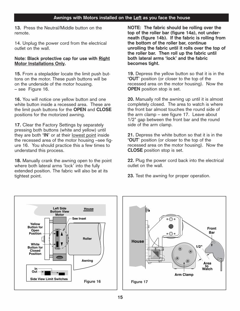
13. Press the Neutral/Middle button on theremote.
14. Unplug the power cord from the electricaloutlet on the wall.
Note: Black protective cap for use with RightMotor Installations Only.
15. From a stepladder locate the limit push but-tons on the motor. These push buttons will beon the underside of the motor housing.– see Figure 16.
16. You will notice one yellow button and onewhite button inside a recessed area. These arethe limit push buttons for the OPEN and CLOSEpositions for the motorized awning.
17. Clear the Factory Settings by separatelypressing both buttons (white and yellow) untilthey are both ‘IN’ or at their lowest point insidethe recessed area of the motor housing –see fig-ure 16. You should practice this a few times tounderstand this process.
18. Manually crank the awning open to the pointwhere both lateral arms ‘lock’ into the fullyextended position. The fabric will also be at itstightest point.
NOTE: The fabric should be rolling over thetop of the roller bar (figure 14a), not under-neath (figure 14b). If the fabric is rolling fromthe bottom of the roller bar, continueunrolling the fabric until it rolls over the top ofthe roller bar. Then roll up the fabric untilboth lateral arms ‘lock’ and the fabricbecomes tight.
19. Depress the yellow button so that it is in the‘OUT’ position (or closer to the top of therecessed area on the motor housing). Now theOPEN position stop is set.
20. Manually roll the awning up until it is almostcompletely closed. The area to watch is wherethe front bar almost touches the round side ofthe arm clamp – see figure 17. Leave about1/2" gap between the front bar and the roundside of the arm clamp.
21. Depress the white button so that it is in the‘OUT’ position (or closer to the top of therecessed area on the motor housing). Now theCLOSE position stop is set.
22. Plug the power cord back into the electricaloutlet on the wall.
23. Test the awning for proper operation.
Awnings with Motors installed on the Left as you face the house

16
APPENDIX C - Soffit Mount
WARNING: Do not remove the plastic safety sleeves from the lateral arms until instructed to do so.
Note: The following instructions are for installing to a level overhang or soffit. If installing to an angledoverhang or rafters, it may be necessary to use Rafter Adapter Brackets. These brackets may be pur-chased seperately and utilized as shown in Figure 18a. Please call Customer Service at 800-670-7071 topurchase the Rafter Adapter Brackets.
Before star t ing:
1. Before beginning, please familiarize yourself with the components of the awning as shown in Figure 18.Find the mounting brackets in the package (they are separated from the awning itself).
RightRoller
Bracket
LeftRoller
Bracket
Location
Location
Location
Location
LocationSoffit
Bracket
SoffitBracket
(a)
Roller (g)
(d)
Right LateralArm
Left LateralArm
Left ArmClamp
FrontBar
(f)
(b)Location
(c)
Location(e)
Right ArmClamp
1
2
3
5
4
AwningFabric
AwningFabric
Valance
Motoror
GearAssembly
SquareBar
CrankLoop
Figure 18
Note: This figure shows awning with motor installedon the right as you face the house.
Note: Number of brackets supplied with awning willvary depending on awning size, see page 17.
SOFFITMOUNTINGHARDWARE
RAFTERADAPTER
MOUNTINGHARDWARE
ROOFHOUSE
ROOFRAFTER(EXPOSED)
SOFFITBRACKET
RAFTERADAPTERBRACKET
Figure 18a

RightRoller
Bracket
LeftRoller
Bracket
Location
Location
Location
SoffitBracket
Roller
(d)
Right LateralArm
Left LateralArm
Left ArmClamp
(f)
(b)
Right ArmClamp
1
2
3
5
4
AwningFabric
Motoror
GearAssembly
SquareBar
CrankLoop
RightRoller
Bracket
LeftRoller
Bracket
Location
Location
Location
Location
SoffitBracket
(a)
Roller (g)
Right LateralArm
Left LateralArm
Left ArmClamp
(f)
(b)
Right ArmClamp
1
2
3
5
4
AwningFabric
Motoror
GearAssembly
SquareBar
CrankLoop
RightRoller
Bracket
LeftRoller
Bracket
Location
Location
Location
LocationSoffit
Bracket
SoffitBracket
(a)
Roller (g)
Right LateralArm
Left LateralArm
Left ArmClamp
(f)
(b)Location
(c)
Location(e)
Right ArmClamp
1
2
3
5
4
AwningFabric
Motoror
GearAssembly
SquareBar
CrankLoop
17
Figure 18bBracket locations for 10’-13’ wide awnings.
Figure 18cBracket locations for 14’-16’ wide awnings.
Figure 18dBracket locations for 17’&18’ wide awnings.

Tools Required
In your package you will find the following tools: a6mm Allen wrench.
For installing the awning on the soffit, under theoverhang, you will need an assistant, measuringtape, two step-ladders, 9/16" socket, chalk line (orstring), Phillips screwdriver, pencil, a level, electricdrill, 1/8" and 1/4" drill bits, 1/2" or 13mm wrenchand a stud finder.
Mounting Line
2. Snap a horizontal straight line on the soffit, usingthe chalk line, the length of the awning. When youposition your chalk line on the soffit, take intoaccount that when retracted, the awning will project10" from the chalk line -- see figure 19.
Note: For ease of mounting the awning to the brack-ets, it is very important that the line be straight.
Locating the brackets
CAUTION: PROPER LOCATION OF THEBRACKETS IS THE MOST IMPORTANT ASPECTOF THE AWNING MOUNTING. IT IS CRITICALTHAT YOU FASTEN THE MOUNTING BRACK-ETS TO THE RAFTERS OR OTHER MAJORSTRUCTURAL MEMBERS.
Even a moderate wind exerts great force on theawning and mounting brackets. This is why it ismost important that all the brackets will be fastenedproperly and securely. Proper location will alsomake it easier to insert the pre-assembled awninginto the supporting brackets.
Note: Mount brackets only in the locations rec-ommended for your size awning.
Note: You will need to use all brackets suppliedfor secure mounting.
For 10 ft thru 13 ft wide awnings, we recommend toinstall the three brackets supplied at the locations (b)(d) and (f) see Fig. 18b. For 14 ft, 15 ft and 16 ft wideawnings, we recommend to install four brackets sup-plied at the locations (a) (b) (f) and (g) see Fig. 18c.For 17 ft and 18 ft wide awnings, use six bracketssupplied at locations (a) (b) (c) (e) (f) and (g) see Fig.18d.
Location (a) – Between the left end of the awningand the left arm, on the rafter nearest to the left end.Location (b) – Between the two arms, on the near-est rafter to the left arm.Location (c) – On the nearest rafter midwaybetween the middle point of the awning and the leftarm.Location (d) – The nearest rafter to the middle pointof the awning. (Size 10’ - 13’ only)Location (e) – On the nearest rafter midwaybetween the middle point of the awning and the rightarm.Location (f) -- Between the two arms, on the nearestrafter to the right arm.Location (g) – Between the right end of the awningand the right arm, on the rafter nearest to the rightend.
Mounting the Brackets into the Soffit
3. On the chalk line you have marked on the soffit,mark the left and the right ends of the awning(points 1 & 5 in fig 18). With the exception of the10’ awning, which measures 123” left to right, allother awnings measure exactly like their definedsize. (For example, a 12ft awning measures 144”from left to right). Using the chart below, mark onthe chalk line the middle point and the points wherethe left and right arm clamps will be (points 2,3 & 4in figure 18 respectively).
Note: The brackets cannot be installed in thearea where the Arm Clamps are located.
10"Closed
Position
House
ChalkLine
Figure 19
18
Size Left arm Clamp Middle- Right arm ClampPoint
10ft 1-1/4” from left end 61” 1-1/4” from right end11ft 7” from left end 66” 7” from right end12ft 8” from left end 72” 8” from right end13ft 14” from left end 78” 14” from right end14ft 20” from left end 84” 20” from right end15ft 26” from left end 90” 26” from right end16ft 32” from left end 96” 32” from right end17ft 38” from left end 102” 38” from right end18ft 44” from left end 108” 44” from right end

4. YOU MUST NOW LOCATE THE RAFTERS INTHE AREA IN WHICH THE BRACKET MUST BEINSTALLED AS EXPLAINED EARLIER IN“LOCATING THE BRACKETS”. To find the rafters,use a stud finder. Be sure to read the stud finderinstructions before usage. Mark the center ofeach rafter, on which a bracket will be installed witha 7” long line.
5. Position the bracket against the soffit, centeredover the vertical line, with the back of the bracketeven with the horizontal chalk line, (see Figure 19),and mark the two holes -- see figure 20.
6. Drill 1/4” pilot holes about 3-1/2” into the rafter.This will prevent the framing from splitting whileinstalling the lag screws.
7. Using a 9/16” socket, install the bracket with the3/8” x 4” long lag screws. Use the flat washer pro-vided under the head of the screw. Make sure notto overtighten the lag screws; doing so may splitthe wood framing or weaken the screw --see figure 20.
8. Repeat for all brackets.
WARNING: FAILURE TO SECURELY FASTENTHE BRACKETS TO THE SOFFIT OR FAILUREOF THE STRUCTURAL MEMBER TO SUPPORTAN AWNING COULD RESULT IN THE COLLAPSEOF THE AWNING AND CAUSE PERSONALINJURY.
Note: If the protective cover was purchasedtogether with your awning proceed to step 9. Ifnot, proceed to step 17 on page 20 to continuewith the installation of your awning.
19
3 1/2" Drill 1/4"Holes
2 Places
3/8" x 4"Lag Screws
2 Places
FlatWasher2 Places
MarkCenters
Figure 20
Protective Cover - Soffit
9. Locate the supplied fasteners and screws usedto secure the protective cover to the soffit--see figure 22.
Note: We recommend installing the fasteners forthe protective cover one at a time, beginning withthe one to the far right. Once the first is installed,you will use the actual protective cover as the tem-plate for the grommet spacing between all holes.
10. Make a mark 1” in front of the bracket--seeFigure 21.
11. On the mark, snap a chalk level line along theentire length of the awning. On the chalk line, markthe location of the right end of the awning. Alongthe chalk line you just made, measure 1” further tothe right of the awning end point and make a mark.This is the location of the first fastener on the rightfor the protective cover--see Figure 22.
12. Place one fastener on the mark. Orient the fas-tener so that the hook opening is facing in towardsthe house -- see figure 22.
House
Soffit1"
FastenerInstallation
Line
Figure 21
1"
1st FastenerLocation
Chalk Line forCover Fasteners
Right end ofawning mark
#8 x 1-1/2"Flat Head
HOUSE Figure 22

13. Using a 1/8” drill bit, drill a pilot hole approxi-mately 1” deep. Secure the fastener with a #8 x1-1/2” Phillips screw supplied.
14. Remove the cover from its packaging. Orientthe cover so that the sewn hem is facing thehouse - see Figure 23. Place the first grommet ofthe protective cover on the first installed fastener.
15. Extend the cover to the left and keep it taut.Then mark the center of the next grommet holecentered on the chalk line.
16. Repeat the previous steps for the remainingfasteners.
Note: The ends of the protective cover aredesigned to extend approximately 1-1/2” beyondthe overall width of the awning.
Securing the Awning into the Brackets
17. Carefully remove all packaging from theawning. DO NOT REMOVE THE PLASTIC SAFE-TY SLEEVES FROM THE ARMS - see figure 10.
18. Seperate the wand from the awning.
19. All Models - Insert a retaining nut into thespecial groove in each bracket - see figure 24.
20. With proper help, lift the awning (with fabricRoller Bar above the Square Bar) into the brack-ets and position so the ends line up with endpoints marked on the wall - see figure 25. Use thefollowing weight chart to decide how much helpyou need.
21. Push the square bar into the brackets andsecure with one retaining bolt in each bracket. Besure to insert the bolt from the bottom of the brack-et up. You might need to apply pressure on thesquare bar to permit insertion - see figure 24.
Return to “Checking your Awning for ProperOperation” page 10 to complete the installationof your awning.
OFF SEASON STORAGE ONLY:
Use the supplied bungee cords to secure cover inplace - see Figure 23. Slide the loop end of thebungee through the bottom grommets from the out-side of the cover, pull the cord over and around thesquare bar and place over the ball that secures thecord.
Remove bungee cords before using your awning.
House
Cover Fastener
ProtectiveCover
BungeeCord
Soffit1"
Ref
20
Figure 23
Sewn Hem
Size Weight Vista Weight Motorized
10ft 78 lbs 84 lbs11ft 83 lbs 89 lbs12ft 90 lbs 96 lbs13ft 95 lbs 101 lbs14ft 100 lbs 106 lbs15ft 105 lbs 111 lbs16ft 110 lbs 116 lbs17ft 115 lbs 121 lbs18ft 120 lbs 126 lbs
RetainingBolt
RetainingWasher
SquareBar
RetainingNut
Figure 24
Figure 25

APPENDIX D
Resetting the Remote TransmitterThis procedure describes the actions needed to reset the Remote Transmitter that was supplied with yourMotorized awning. This procedure should only be performed if the Remote Transmitter does not operatethe Motorized awning. Please review the steps below to familiarize yourself with the procedure beforeattempting to complete them.
• Verify that the red light on the remote transmitter comes on when you press and hold the button. Ifthe red light does not come on at all or blinks for less than 5 seconds, you will need to replacethe battery (see Care and Maintenance section on page 12).
• Press the NEUTRAL (middle) button on the transmitter.• Unplug the power cord from the wall.• Insert the wand into the Override crank on the motor and
manually open the awning approximately 3 feet but do notcompletely open.
• Plug the power cord back into the wall and make sure thatthere is electricity available. Let the awning sit for oneminute, undisturbed, without pressing a button on theremote transmitter or unplugging the cord from the wall.
• Unplug the power cord from the wall for 2 seconds.• Plug the power cord back in for 10 seconds.• Unplug the power cord for 2 seconds.• Plug the power cord back in and leave it plugged in.
NOTE: The motor may rotate approximately 2 feet in onedirection and stop.
When the motor stops, press and hold the programming button on the back of the Remote Transmitter (seefigure A) for 5 seconds until the motor ‘jogs’, then release. (A ‘jog’ is a short back and forth movement ofthe motor).
Activate the transmitter by pressing the OPEN and CLOSE buttons at the same time, the motor will jog.
Press the programming button on the back of the Remote Transmitter until the motor jogs and release.
NOTE: If the motor does not operate, you will have to clear the OPEN/CLOSE stop settings on the motor.Please complete ONLY steps 1 thru 5 of Appendix B (page 14) if your motor is on the right side, or steps 13thru 17 of Appendix B (page 15) if your motor is on the left side. After clearing the OPEN/CLOSE stop settings,verify if the transmitter operates the awning. If not, return to this page and repeat the procedure listed above.
Your Remote Transmitter is now reset to operate your Motorized awning. Test the awning for proper opera-tion. If you cleared the OPEN/CLOSE stop settings on the motor, go to Appendix B on page 14 to resetthem.
Add/Delete a Control Device (Transmitter, Remote Wall Switch, Wind Sensor)To ADD an additional Control Device (not the one that was supplied with the awning):
• Press the programming button on the back of the transmitter that was supplied with the awninguntil the motor ‘jogs’- see Figure A.
• On the additional Control Device, press the programming button until the motor‘jogs’, then release.
If you wish to DELETE a control device, simply repeat the 2 steps listed above.
21

TROUBLESHOOTING
22
Problem with Installation
Stud finder is not locating a studon my exterior wall
Can I "hard-wire" a switch intomy home?
How low can the pitch be set?
Problem with Appearance
Fabric wrinkles when the awningis opened/closed
Lateral arms (elbows) are noteven when awning is retracted
The roller bar and fabric appearto bounce when opening andclosing the awning.
My fabric is rubbing against thearm clamps when it isopening/closing
Solution
You may need to locate a stud on the inside wall and transferthe location to the outside wall. Make sure to measure from acommon point (window/door frame, etc).
SunSetter cannot be responsible for any changes in the electri-cal configuration of the motorized awning. Have your electriciancontact Somfy (the motor manufacturer) directly via their web-site, www.somfysystems.com. Hardwiring will void the warran-ty on the motor and on other awning electrical components.(Remote, cable, etc).
As low as a 45 degree angle.
Solution
The awning fabric has a hem along both ends of the material;some wrinkling is a characteristic of the extra thickness alongeither edge. This wrinkling may be more noticeable whenretracted and after prolonged periods when the awning is notused. This condition is normal. Leaving the awning open inwarm weather should minimize the wrinkling over a period oftime.
• Each lateral arm is supported individually to the square bar.Therefore, it is normal that when the awning is closed, the armsmay not necessarily be even with each other when viewed fromthe front or underside of the awning.• Insure that fabric is evenly centered on Roller bar and FrontBar. This will assist the lateral arm in closing more evenly.
The roller bar that holds the fabric is supported only at theextreme ends and it bows toward the center. As the Roller Barrotates, it may move up and down toward the center. This is anatural tendency of the bar and may be more noticeable withlarger sized awnings.
• The fabric should not come in contact with the hardwarewhen it is opening or closing. Check and make sure the fabricis rolling over the top of the roller bar. (see Appendix B, figure14a and 14b).• Check the setting of open stop. It should be set when botharms are fully extended and in the "locked" position arms. (seeResetting limit push buttons, Appendix B)

Problem with Motor or Gear
When opening or closing theVISTA awning the drive unit binds,skips or spins freely.
After installing, the awning will notfunction
The red light on the remote trans-mitter does not come on when Ipress and hold the button
Awning rolls out but will notretract
Awning retracts but will not rollout
Awning rolls out and keeps goingand fabric starts to sag
Awning will not open or retractusing the Manual Override Crank
Remote transmitter, can I usemore than one
After opening and closing theawning several times, the motorsuddenly stopped working andwill not close or open the rest ofthe way
When operating my awning theGFI on the outlet keeps trippingand interrupting the power supplyto the awning
Solution
The drive unit gears may have been stripped or damaged dur-ing operation. Please call Customer Service for possiblereplacement.
• Is there power to the receptacle?• Verify that the red light is on the remote transmitter comes onwhen you press and hold a button• If red light does not come on, remove battery and reinsert inslot and try pushing button again, If no light - see changingbattery on page 12.• You may need to reprogram the remote transmitter – seeAppendix D• You may need to reset the OPEN/CLOSE limit push buttonson the motor – See Appendix B
• Remove the battery and reinsert in slot and try pushing buttonagain, if no light replace battery.• Replace the battery (CR2430) following the instructions onpage 12
Reset the OPEN/CLOSE limit push buttons using the installa-tion instruction manual – see Appendix B
Reset the OPEN/CLOSE limit push buttons using the installa-tion instruction manual – see Appendix B
Reset the OPEN/CLOSE limit push buttons using the installa-tion instruction manual – see Appendix B
The remote must be in the NEUTRAL position in order for the man-ual override to operate correctly when using the crank. If neces-sary, you can also unplug the cord from the electrical receptacle.
Yes, you can purchase an additional transmitter from SunSetterProducts and follow the installation instruction manual –Appendix D, to set the additional transmitter
The overtemperature sensor has temporarily shutoff the motor.The motor will resume normal operation after about 15 minutesof cooling down.Note: If the awning is in the closed position and ambi-ent temperature is elevated, it might take a little longer.
• First test the GFI by plugging in another appliance (such as ahairdryer) to insure outlet is working properly, if OK.• Test awning by getting power from other outlet inside thehouse using an extension cord, if OK.• There may be moisture in the motor housing causing the GFIto trip, please allow motor to dry over 2-3 sunny days. Motor isdesigned to operate if it gets wet and dries out.• Installing the SunSetter cover over your awning will reducethe risk of rain-water affecting the operation of the motor.
TROUBLESHOOTING - Continued
23

24
HOW TO DRAIN RAIN WATER FROM THE AWNING FABRIC
WARNING: THE SUNSETTER AWNING IS NOT DESIGNED TO HOLD THE WEIGHT OF RAINWATERPOOLING ON THE FABRIC. ACCUMULATION OF RAINWATER ON THE FABRIC COULD COLLAPSETHE AWNING AND CAUSE SERIOUS INJURY!
If, for any reason, rainwater accumulated on the fabric, follow the instructions below to remove thewater. You will need a helper for this procedure.
WARNING: NEVER WALK UNDER AN AWNING WITH WATER ACCUMULATED ON THE FABRIC!THERE COULD BE A TREMENDOUS AMOUNT OF WEIGHT ON THE AWNING AND THE FRAMECOULD COLLAPSE AT ANY MOMENT AND CAUSE SERIOUS INJURY!
1. Connect a common garden hose to your outside water faucet.
2. While standing in front of the awning (BUT NOT UNDER THE AWNING), visually observe where isthe deepest point of the water pooling on the fabric.
3. Hold the open end of the garden hose about head high. DO NOT ALLOW ANY WATER TO RUNONTO THE FABRIC.
4. Have a helper turn the water faucet on. Let water run ONTO THE GROUND until there is a solidstream of water.
5. Continue to hold the end of the hose head high and have your helper turn the water OFF. Leave thehose connected to the faucet.
6. Place the end of the hose over the front of the awning and let the open end of the hose slide into thedeepest point of the water pool. DO NOT GO UNDER THE AWNING!
7. While the open end of the hose is UNDER THE SURFACE OF THE WATER, have your helper dis-connect the water hose from the faucet and lay it on the ground.
8. The siphon caused by the water running out of the hose will drain the water from your awning. Let thewater continue to drain until the flow of the water through the hose stops.
9. While keeping the end of the hose submerged, move it around on the fabric to keep it under the sur-face of the water to fully drain the water from the fabric..10. When the drain stops, make sure most of the water was drained. If not, repeat the process untilmost of the water is drained off of the fabric.
11. Close the awning and let the rest of the water run off totally from the fabric.
12. Inspect your awning for damaged parts, and check for normal operation.

25
A. WHO GIVES THIS WARRANTY?SunSetter Products, 184 Charles Street, Malden, MA 02148.
B. WHO IS ENTITLED TO THIS WARRANTY?This Warranty applies only to the original purchaser who paid forthe product and may not be assigned or transferred to subse-quent owners. This Warranty applies only to products purchasedand installed in the US.
C. WHAT ARE THE RESPONSIBILITES OF SUNSETTERPRODUCTS UNDER THIS WARRANTY?Subject to the terms and conditions set forth herein, SunSetterProducts will furnish replacements for parts found by SunSetterProducts to be defective in design, manufacture or assembly,under each specific component or product warranty as set forthbelow.
D. WHAT ARE THE RESPONSIBILITES OF THE ORIGINALPURCHASER UNDER THE WARRANTY?1. Before any claims may be made under this Warranty, the orig-inal purchaser must have paid in full for the product coveredunder the Warranty, according to the terms and conditions of thepay-plan defined in the original order. IF THE PURCHASERHAS FAILED TO MAKE FULL PAYMENTS ACCORDING TOTHE SPECIFIC PAY PLAN FOR THE PRODUCT, THIS WAR-RANTY SHALL BE NULLIFIED AND SUNSETTER PRODUCTSSHALL BE RELIEVED FROM ANY RESPONSIBILITY OR LIA-BILITY UNDER THIS WARRANTY. The purchaser agrees andacknowledges that this Warranty agreement constitutes anexecutory contract.
2. The purchaser must use care in installation, maintenance,operation, use, and storage of the product in accordance withthe instructions contained in the owner's manual. ANY FAILURETO INSTALL, MAINTAIN, OPERATE, USE AND STORE THEPRODUCT IN ACCORDANCE WITH THE INSTRUCTIONSCONTAINED IN THE OWNER'S MANUAL WILL NULLIFY THISWARRANTY AND RELIEVE SUNSETTER PRODUCTS FROMANY RESPONSIBILITY OR LIABILITY UNDER THIS WARRAN-TY.
3. Promptly notify SunSetter Products of any claims.
4. The purchaser may be required to provide a photograph ofany defective parts. The purchaser may also be required to paya deposit until the defective parts are returned to SunSetterProducts for inspection. The purchaser must obtain a returnauthorization form from SunSetter Products' customer servicedepartment prior to the return of any merchandise and after hav-ing received such authorization, return the part or product,freight prepaid, to SunSetter Products.
E. WHAT IS COVERED UNDER THIS WARRANTY?1. The following components of the SunSetter Lateral ArmAwning and its accessories (defined as accessories attached tothe awning) are covered under this Warranty, subject to the limi-tations set forth below. These components have a five (5) yearlimited (prorated) warranty, against manufacturer's defects asoutlined below:
(a) Should the purchaser promptly notify SunSetter Products ofsuch defects within one year (12 months) from the date of theoriginal purchase, the defective component will be replaced atno charge.
5-Year Limited Warranty – Awning and AccessoriesVISTA and Motorized Models Only
(b) After one year but within five years (60 months) from the dateof the original purchase, a defective component will be replacedupon the purchaser's payment of 1/60th of the full retail cost ofthe component for each month of use prior to the claim.
2. Covered Components:
STRUCTURAL SUPPORTS, which include the lateral arms, thesquare bar, the front bar and all other attached supports arewarranted not to fail for five (5) years provided that the compo-nents are not subjected to excessive winds or water pooling onthe fabric.
ROLLER BAR is warranted for five (5) years against any and alldamage including cracking and permanent bowing that wouldaffect the performance of the awning, provided that the awningis not subjected to excessive winds or water pooling on the fab-ric.
FABRIC is warranted for five (5) years against:
(a) Excessive fading under normal conditions if maintained, oper-ated, used, and stored in accordance with the instructions con-tained in the owner's manual.
(b) Mildew on the fabric. Mildew will not form on the fabric itself,but may form on dirt and dust that have not been removed fromit. Please see maintenance instructions for proper cleaning-out-lined in owner's manual.
(c) Excessive cracking or peeling under normal conditions ifmaintained, operated, used, and stored in accordance with theinstructions contained in the owner's manual, and provided thatthe awning is not subjected to excessive winds or water poolingon the fabric.
GEAR MECHANISM (VISTA Model only) is warranted for five(5) years not to fail under normal conditions if maintained, oper-ated, used, and stored in accordance with the instructions con-tained in the owner's manual.
ELECTRIC MOTOR (Motorized Models only) is warranted for five(5) years not to fail under normal conditions if maintained, oper-ated, used, and stored in accordance with the instructions con-tained in the owner's manual.
AWNING ACCESSORIES (defined as accessories attached tothe awning) are warranted for five (5) years not to fail under nor-mal conditions if maintained, operated, used, and stored inaccordance with the instructions contained in the owner's manu-al.
F. WHAT IS NOT COVERED UNDER THIS WARRANTY?1. The SunSetter awnings are not designed to be used for car-ports and are not designed to be installed on moving vehicles.Any damage that results from the Purchaser's use of SunSetterawnings for carports or on moving vehicles is not covered bythis warranty.
2. Any failure or damage of the components that results fromany intentional or negligent actions by the purchaser or by anyother person is not covered by this Warranty.

26
3. It is the responsibility of the purchaser to securely fasten theawning to studs, joists, headers or other structural members.Any failure or damage that results from the awning falling fromits installed position is not covered by this Warranty.
4. Labor charges connected with installation of replacementparts are not covered by this Warranty.
5. Freight expenses to and from SunSetter Products in shippingdamaged or replacement parts are not covered by this Warrantyand must be paid by the purchaser.
6. Stretching of fabric or damage to any structural componentcaused by wind or water pooling on the fabric or any otherweather are not covered by this Warranty.
7. Any modification or addition to the awning structure and sup-port system or to the electric motor or its wiring will nullify thisWarranty and relieve SunSetter Products from any responsibilityor liability under this Warranty.
G. GENERAL PROVISIONS AND LIMITATIONS
1. THE WARRANTY GRANTED HEREIN IS THE EXCLUSIVEREMEDY FOR THE PURCHASER. SUNSETTER PRODUCTSMAKES NO OTHER WARRANTIES TO THE PURCHASER,EXPRESS, STATUTORY, IMPLIED OR OTHERWISE AND ALLIMPLIED WARRANTIES, INCLUDING WITHOUT LIMITATIONS,IMPLIED WARRANTIES OF MERCHANTABILITY AND FITNESSFOR A PARTICULAR PURPOSE, ARE HEREBY DISCLAIMED.
2. TO THE EXTENT PERMITTED BY LAW, SUNSETTER PROD-UCTS SHALL HAVE NO LIABILITY TO THE PURCHASER ORANY OTHER PERSON FOR INCIDENTAL, SPECIAL, CONSE-QUENTIAL, INDIRECT OR SIMILAR DAMAGES OF ANY KINDOR NATURE WHATSOEVER, WHETHER ARISING OUT OFBREACH OF WARRANTY OR OTHER BREACH OF CONTRACT,NEGLIGENCE OR OTHER TORT, OR OTHERWISE, EVEN IFSUNSETTER PRODUCTS SHALL HAVE BEEN ADVISED OFTHE POSSIBILITY OR LIKELIHOOD OF SUCH POTENTIALLOSS OR DAMAGE. IN NO EVENT SHALL SUNSETTERPRODUCTS BE LIABLE FOR LOSS OF PROFITS AND/ORWAGES.
3. Some states do not allow limitations on how long an impliedwarranty lasts, or do not allow the exclusion or limitation of inci-dental or consequential damages, so the above limitations maynot apply to you.
4. This warranty gives you specific rights and you may haveother rights which vary from state to state.
5-Year Limited Warranty – Awning and AccessoriesVISTA and Motorized Models Only (continued)

REV. 11/10/08 ©SunSetter Products, a Massachusetts Limited Partnership, 184 Charles Street, Malden, MA 02148