supa-tuna – v4 the best tuning investment you will ever make
TRANSCRIPT

1
SUPA-TUNA – V4
The best tuning investment you will ever make
2
Contents
1. Introduction
2. History of my tuning lights
3. My Guarantee
4. Overview
5. Carby Basics
6. Basic tuning
a. Side Line tuning
b. Basic tuning
7. Advanced tuning
8. The black art of “reading a plug”
9. During Race Indications
a. Engine Specifics
10. Detailed Theory of Operation
11. Installation
a. Display Unit
b. O2 Sensor
c. O2 Sensor Wire
d. O2 Exhaust Adapter Nut
12. Power Selection
a. Auto ON-OFF
b. Manual ON-OFF
13. Battery Unit
a. The Battery
b. Changing the Battery
14. 02 Sensors – do they wear out ?

3
Introduction
First and foremost I would like to thank you for purchasing my latest version of my “Supa-Tuna”
tuning lights. As you would already be aware, these units are significantly cheaper than any
other that is currently available. This is not to say that they are any cheaper in design or
construction, in fact, I would suggest that my lights are possibly most advanced tuning lights
available on the market. This has not happened by accident, but rather through extensive research and development and testing both on the track and on the Dyno.
My confidence in the quality of this product is reflected in my personal guarantee that I offer to
not only the original purchaser, but also anyone who purchases a second hand set of my
lights.
If you have any questions, or require clarification of any section of this manual, I would be
happy for you to contact me on the mobile number listed below or via e-mail. There is also
information contained on my web site that may be of assistance.
Dave Price
Mobile – available 7 days (no calls after 8pm unless urgent)
0410 179 037
Web Page
www.supa-tuna.com.au

4
History
I started racing karts in 1982 at 13 years of age in Junior Class Australia – the predecessor to what is now referred to as Junior Clubman. Back then we ran fully port and polished KT100S
motors at an all up class weight of 105Kg. The karts were very quick in a straight line, but
compared with today’s karts, would be nowhere near competitive on the track. Who needs
handling when you have straight line speed !
My involvement with karting was interrupted when I joined the RAAF in 1987. I dabbled with
various forms of motor sport including Rally, Drags, Circuit racing and the odd stint in karts in
Melbourne. I made serious return to Karting in 2004.
As an Electrical Engineer with a background in Data Acquisition systems, Meteorology and
Instrumentation, I recognised that there was a need for a more accurate method of tuning a
kart engine than just by ear or reading a plug.
In 2004 there were two major brands of tuning lights available on the market, and after
repairing a number of these for local karters, I realised that what they were being sold was nothing more than a $16 Jaycar Electronics Kit. These kits were being assembled and sold,
some at close to $400.
The first set of lights I used were a Jaycar kit, and I subsequently destroyed a motor in the
process as the kit is designed for automotive applications running straight ULP. I quickly discovered that the requirements of a 2 stoke kart engine is vastly different to a car. I
constructed my first prototype and spent many hours on testing both on the dyno and at the
track to establish a calibration that was consistent, reliable and safe.
Version History
Version 1 – The tolerances of the other brands of tuning lights resulted in inconsistent displays and certainly not good enough for me to trust with my motors. I designed my own circuit board,
using high tolerance components and added a feature to allow the intensity of the LED’s to be
varied. So many people I spoke with were interested in buying a set from me, that I started making them to sell.
Version 2 – Evolutionary change saw improved electronics with a new surface mount circuit board. This included an increase in the number of LED’s from 8 to 9. I also developed a new
calibration point. This version was used by me to qualify 2nd at the QLD open State
championships in 2006.
Version 3 – Electrically the same as Version 2 but both the On-Off switch and the LED intensity control were combined into a single switch.
Version 4 – The intention was to provide an unparalleled product. A number of Improvements have been included in the design.
Features now include:
• Custom “curved” case – designed to match the shape of most lap computers on the market.
• 9 LED design – super bright LED’s ensure clear visibility even while racing in full sun.
• Battery – single “AA “battery ensures that a replacement is both easy and cheap.
• Battery holder – Robust aluminium construction with an inbuilt battery indicator.
• Battery Lead – For people running Tag engines with an onboard battery, an alternate battery lead can be supplied
5
Features continued:
• Sensor – Denso, continually prove the most reliable sensors on the market. I have customers with over 18mths of use from one sensor. Because my calibration is more
accurate than the other brands of tuning lights, there is less un-burnt fuel / oil in the
exhaust gas , meaning that the sensors last longer.
• Auto ON-OFF function, no more flat batteries as it turns on and off with the motor
My Guarantee
This unit is personally guaranteed by to be free of defects in materials and workmanship for 2
years from date of purchase. (Excludes Sensor)
I will repair or replace the unit (at my option) without charge and reimburse you for shipping
costs if the unit should prove defective.
This guarantee does not include damage caused by accident, unreasonable use or
modification.
I also offer a free recalibration of each unit at anytime during the unit’s life at your shipping
costs.
To date (Feb 2009), I have not had a single unit fail. All repairs I have performed to date have been as a result of accidental damage, being mainly damage to the power switch or LED’s
being hit while loading karts into the trailer etc.
Warning
This unit is NOT WATER PROOF. Use in rain conditions will be at the user’s risk.
Some people have used Glad-wrap /Cling film etc to seal the unit. If your unit
becomes wet, remove from the Kart, remove 6 screws from on the back of the unit
and carefully lift the lid.
The unit should be allowed to dry out, a domestic hair dryer could also be used to
speed the drying process, however DO NOT re-connect the battery or turn the unit
on until completely dry. If in doubt – PLEASE call me
If the unit is excessively wet – washing the circuit board with methylated spirits or
preferably isopropyl alcohol and blowing with low pressure compressed air is the
best method. Some electronics shops (Dick Smith or Jaycar), sell aerosol cans of
circuit board cleaner ideal for this use.
If in doubt – PLEASE call me !
6
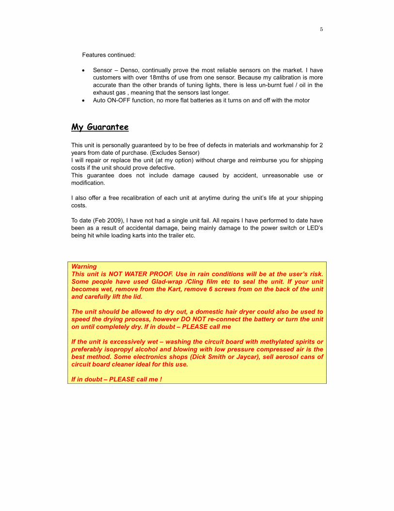
Overview
The Supa-Tuna V4 System comprises 1. Display unit (with ‘Yellow’ Ignition Sense wire)
2. Oxygen sensor and lead.
3. Power source ( Battery Pack or Optional 12V Battery lead)
4. Ignition sensor wire
5. Aluminium Bracket 6. Weld in Plug
Components
The basic principle is that an automotive oxygen sensor is used to measure the amount of
Oxygen (O2) in the exhaust gas. By displaying this relative O2 reading, we can adjust the
Air-Fuel ratio using the High and low speed jets on the carby, to achieve an OPTIMUM A/F
ratio. The amount of O2 remaining in the exhaust gas is a direct indication of how efficiently the
motor has burnt the available fuel. The more efficient the burn, the closer you get to the
maximum horsepower the motor can produce to.
Excess O2 means that there was insufficient fuel available and hence a LEAN mixture. Vice
versa, a depleted O2 reading means a RICH mixture.

7
The colour of the LED’s and their position on the display gives a fast, visual reference to work
to.
From Left to right, there are 2 x Amber LED’s, 4 x Green LED’s and 3 x Red LED’s – The colour of the LED’s were chosen to replicate the standard traffic light conditions.
Amber SLOW Too Rich
Green GO Optimum
Red STOP Too Lean
You will also notice that the LED’s are positioned in a sweeping arc. This is a visual cue to
performance with the higher the position, the better the performance. Generally speaking the
second last GREEN LED will provide the BEST power, either side of that and the power is
slightly reduced.
AIRCOOLED 2 stroke Kart motors, rely on the Air-Fuel mix to do 3 things
• Provide a source of energy
• Provide lubrication • Provide some cooling
Prolonged performance can be gained by running the motor slightly richer than Optimum. This
means having one of the first three GREEN LED’s illuminated.
On any given day, changes in Air Temperature, Humidity (water content), Atmospheric
pressure, Fuel Temperature, Fuel Type (Premium v standard), etc will all have an effect on how the engine performs. As Air density changes, the carburetor performance will also change,
requiring different settings to achieve optimum performance. However, even with these
changes, the optimum A/F ratio of 14.7:1 required to make maximum horsepower remains
relatively constant. The tuning lights are designed to display the actual A/F ratio so that you
can make carby adjustments, achieve an optimum ratio and hence Maximum HP.
One advantage of Tuning lights is that you can achieve maximum performance
regardless of rapid changes in ambient weather conditions. On the Dyno, a 5
degree drop in Inlet air temperature created a 15 degree drop in Exhaust temp and a 4% increase in HP. The position of the low speed jet was ¼ turn Richer.
The following pages contain images of the various LED’s and are designed as a guide to what
you should expect to see and tune to.
8
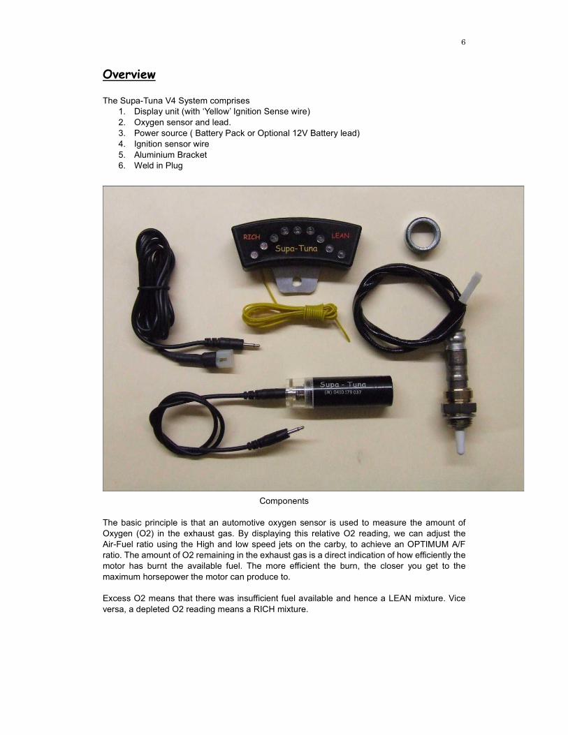
Picture 1
VERY RICH You will notice that the last RED LED is faintly illuminated. This indicates that the unit is ON
and working correctly.
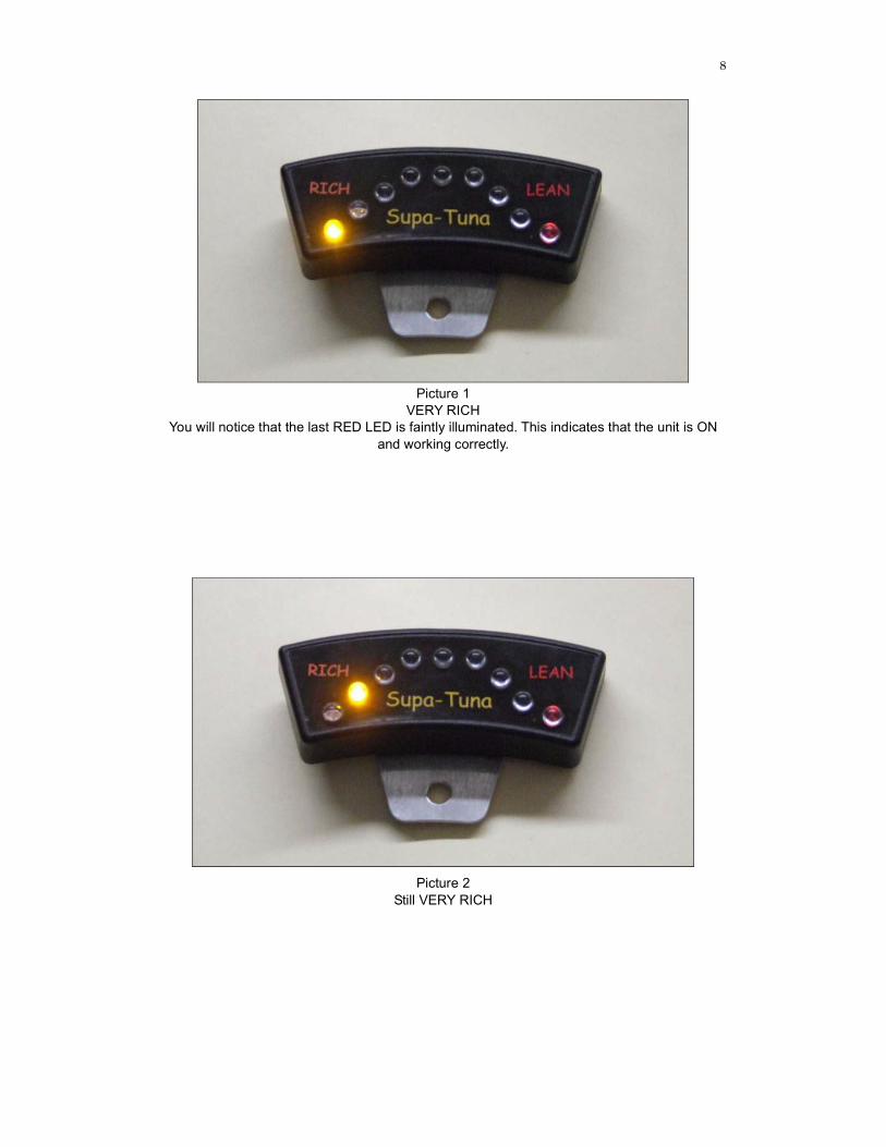
Picture 2
Still VERY RICH

9
Picture 3 Still RICH but VERY safe
Picture 4
With this LED illuminated, it is starting to get close to the ideal tune.
10
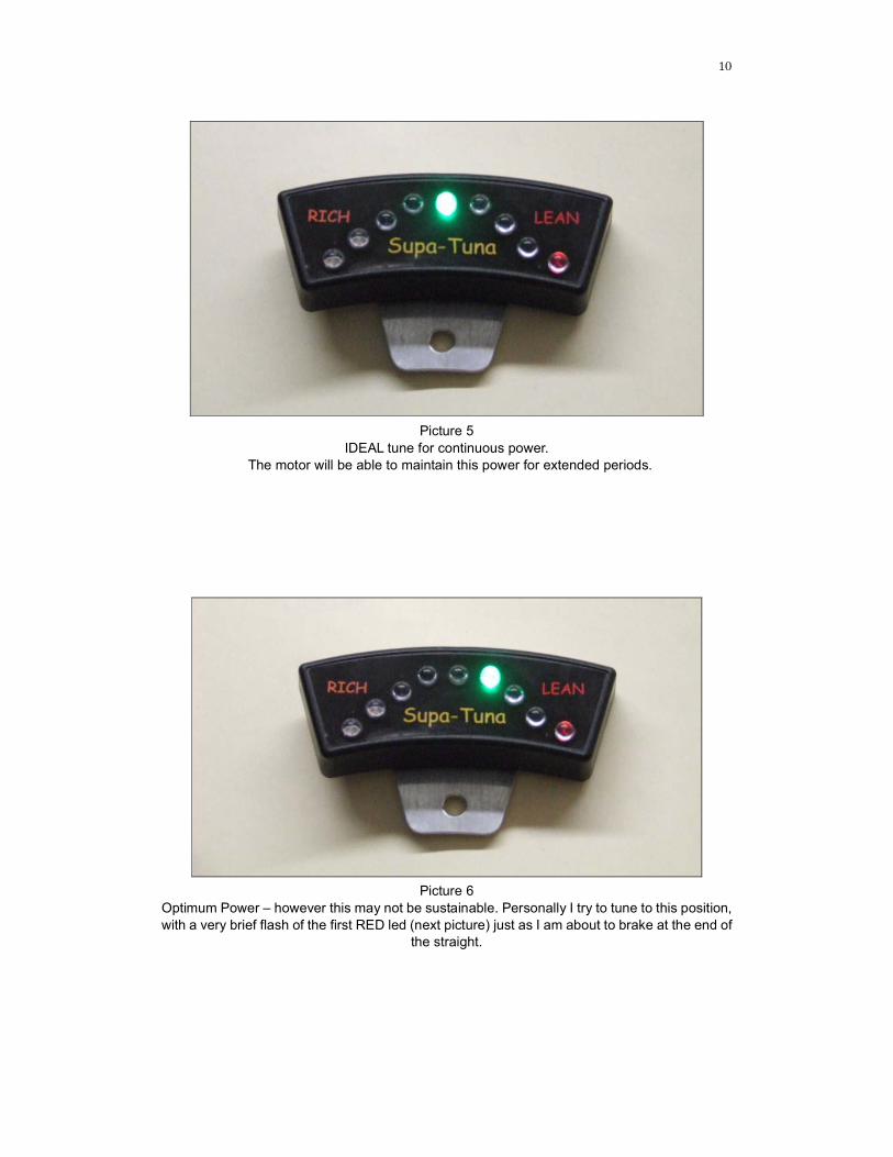
Picture 5
IDEAL tune for continuous power.
The motor will be able to maintain this power for extended periods.
Picture 6
Optimum Power – however this may not be sustainable. Personally I try to tune to this position,
with a very brief flash of the first RED led (next picture) just as I am about to brake at the end of the straight.
11
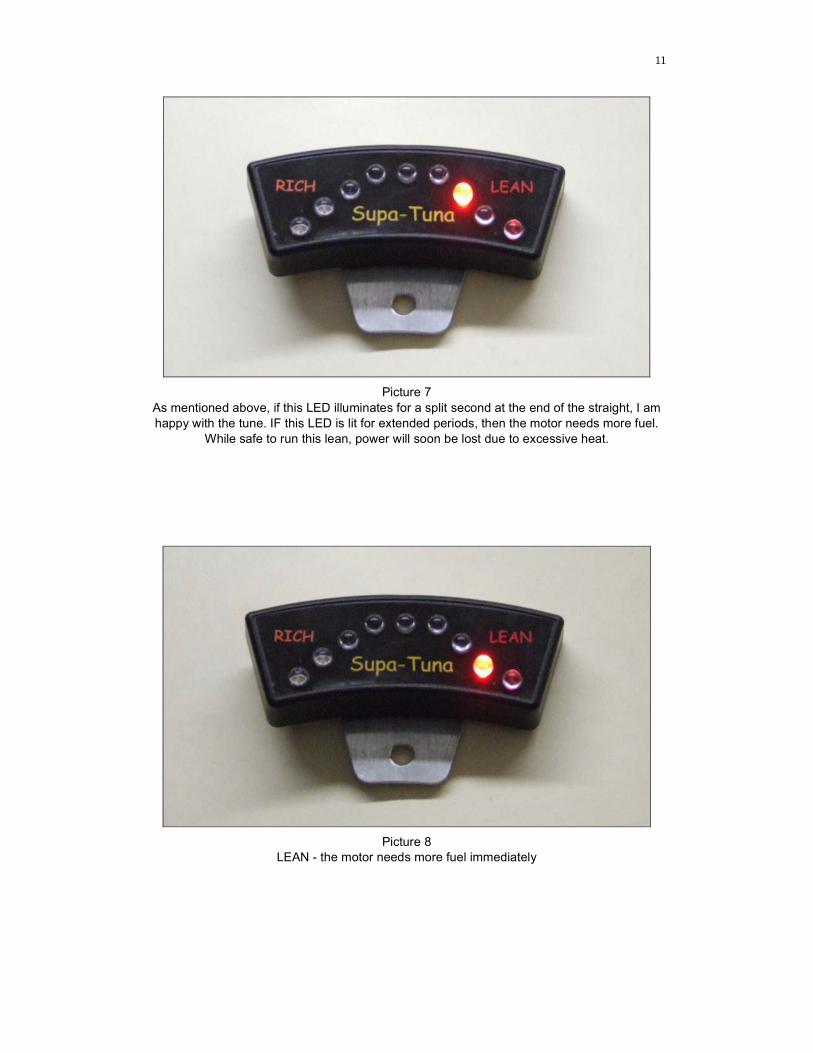
Picture 7
As mentioned above, if this LED illuminates for a split second at the end of the straight, I am
happy with the tune. IF this LED is lit for extended periods, then the motor needs more fuel.
While safe to run this lean, power will soon be lost due to excessive heat.
Picture 8 LEAN - the motor needs more fuel immediately
12
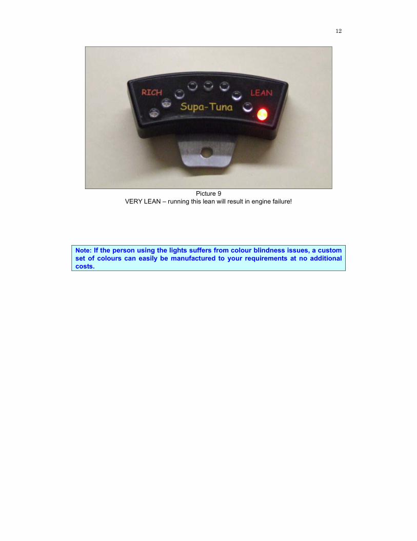
Picture 9
VERY LEAN – running this lean will result in engine failure!
Note: If the person using the lights suffers from colour blindness issues, a custom
set of colours can easily be manufactured to your requirements at no additional
costs.
13
Carby Basics
Before we get into the specifics of tuning, let’s cover some carby basics. In this section I will refer to the Walbro Carby, given that it is the most common carby used in karting throughout Australia however, the tillotson and others will also follow the same basic principles. With the Walbro carby (and most others) there are only 2 main fuel routes each with a corresponding “tap” referred to as a mixture needle or jet. These jets are used to control the amount of fuel delivered to the motor and rely on solely on airflow through the venturi or throat of the carby. As rpm increase, airspeed through the carby also increases, increasing the amount of fuel delivered (and required). The Low speed jet is used to control fuel flow to the motor from idle to about 9000 rpm and the High speed from 11000 rpm upwards. You will notice that there is a 2000 rpm gap which is taken care of by the “transition jet”, which is not adjustable. These rpm figures are arbitrary only, depending on the weather on the day, and manufacturing tolerances, they will vary. Also it is important to understand that they are not absolute figures. By that I mean that the low speed, while effective up to 9000 rpm – will still continue to operate and deliver fuel well into the High rpm rev range. The same is applicable for the high speed jet – it does have some effect at low rpm. What this means is that for maximum HP, the carby must be tuned on both the high and low. Your individual carby will most likely display unique characteristics when compared with another seemingly identical carby. This is where the tuning lights become an invaluable tool for getting the best performance from your engine / carby combination. If your carby has been modified (also sometimes referred to as blueprinted or drilled). It is likely to display vastly different characteristics than a standard carby. Most engine builders will offer this as an option and what works on a KT100S will not work on a KT100J, because of the different rpm / fuel requirements.
KT100J– These motors don’t utilise the Walbro carby to its fullest potential. By this
I mean that the carby is actually oversized for the J and is really not making enough
RPM to activate the HIGH speed fuel delivery circuit. This is why most J drivers
crack the High jet (1/8 – 1/4 turn) and tune off the low jet – well that is unless they use tuning lights !!!
14
Basic tuning… I will break tuning into the following categories.
1. “Side line” tuning 2. Basic tuning (KT100J) 3. Advanced tuning
I would recommend that you read all sections before deciding on where you are going to start from, regardless of your driving experience. I would also recommend that you dedicate practice time to learning to tune, do not wait until race day. Tuning needs to be second nature, not something that you need to think about while concentrating of driving., you wouldn’t try to learn how to changes gears while doing your driving test !!
Side Line tuning
This is a quick guide for dads to gain confidence about what their driver is seeing on the display before moving into the basic tuning section. The easiest way to achieve this is to stand at a point along the straight, approximately ¾ of its length. Be sure to pick a spot that is unlikely to distract the younger drivers and I would not recommend that you ever offer tuning advice while they are driving. Wait till they return to the grid before making an adjustment. If you feel it’s that critical, call them in, make the adjustment then send them back out.
I have specifically selected super bright LED’s that have a wide viewing angle. This
allows Dad to see the tune from the side of the track. If you race at night, the LED’s
will illuminate the front of the helmet, race suit etc and can be easily seen up to a
few hundred meters away.
Do not forget that at this stage of their karting life, tuning is going to be to ensure that the engine is safe – not put them on the front row of the grid !
Basic Tuning
For the new karter, the “only” time that a tuning correction should be made is at the end of the straight, with MAX RPM and full throttle. This does make it easy for our younger drivers, as the end of the straight, while fast, is usually uneventful and they tend to have a little time on their hands. Generally, at all other times, the lights may initially be difficult to understand partially due to inconsistent air/fuel mixture but also that a lot of newer drivers will be concentrating so heavily on driving, that they will not even notice a trend to lean or rich. I know that I initially struggled to understand what I was seeing, but rest assured, once you get to know what you’re looking at, its pretty simple to follow and a very valuable race tool. This process listed below may seem very basic, but I have proven that it is the most effective method of getting kids (and new karters) comfortable with tuning basics. I have found that it’s more difficult for Dad to trust his young driver than getting the driver to learn to tune !! I have also assumed that we are dealing with a J motor but the basic principles are the same for any motor.

15
1. Where are the jets ? Have the driver sit in the kart, wearing a helmet and race gloves with both hands on the wheel. Without looking at the carby, reach down, feel for and identify the both the low speed and high speed jet. They need to be able to identify both jets, however will only need to adjust the low. 2. What Direction? Once they are familiar with the positions, we need to ensure that they know which way to turn the jet. Leaner is clockwise and Richer is anticlockwise. This is a good time for Dad can point to a LED and have the driver adjust the low speed jet in the correct direction. 3. How far do you move it? Each carby will be slightly different and especially if it has been modified. I believe that new karters should not use “Blueprinted”, “drilled” or modified carbies as they can be quite difficult to use, even as an experienced karter, I have a carby that remains in a box in my shed because it is too difficult to tune. 4. When do I tune? What I have found best is to get the driver ready to tune soon after coming onto the straight. The right hand can be moved across to the carby in preparation well before its needed, which is typically around the start finish line or a point about ¾ the length of the straight. 5. What do I look for? As you travel down the straight, with the throttle fully open, the engine revs will be rapidly increasing. As this occurs, the engine becomes more efficient at burning the air fuel mixture and this is generally seen on the display as the LED’s progressively work towards the right. If the initial tune is close, they may be displaying the first green but will start to move into the flat green section. Regardless of what LED is lit as you enter the straight, as rpm increases, the display will a trend towards the right, ie leaner. 6. When do I take a reading? For basic tuning, as the kart crosses the Start/ Finish line, a quick glance down is all that is required. It is important that the driver does not focus on the lights to the detriment of the track or other competitors. I have seen one midget drive off the end of the straight into the sand trap. 7. With the driver having his hand on the jet early, it is possible to take a reading, and then make a quick change before the end of the straight. As a general rule (assuming a standard carby) if the low speed jet is moved approximately 1/8th of a turn it will move the LED’s one stage left or right. For clubman, 1/8th of a turn on the high will achieve the same. 8. How should I tune? What you should see as you enter the straight, will be the lights will indicate rich, and continually move towards the right until at maximum rpm, one of the LED’s is illuminated. This is showing you what the mixture is at that point on the track. If at maximum RPM, the display is showing AMBER (Picture 1 or 2) – The motor is too rich. Close the low speed jet (clockwise) to Lean it off little. This adjustment should be made before the end of the straight, then on the next lap, check the display and make a further adjustment if required.
16
If at maximum RPM, the display is showing RED (Picture 7, 8 or 9) – The motor is too lean, and needs to be given MORE fuel immediately. Make an aggressive adjustment to the Low speed jet of ¼ to ½ a turn (anticlockwise) to RICHEN the mixture and on the next lap, recheck the display and adjust as required. If at maximum RPM, the display is indicating GREEN (Picture 3, 4 or 5) – the tune is good, no adjustment is necessary – re check on the next lap and adjust as required. If at maximum RPM, the display is indicating GREEN (Picture 6) – the tune is starting to become LEAN. A very small increase of 1/8th of a turn (anticlockwise) to RICHEN the LOW would be a good idea - re check on the next lap and adjust as required. Typically the as the motor heats up, it becomes more efficient at burning the fuel charge and hence will trend towards lean if left unchecked. Depending on the individual characteristics of the motor (compression, head shape, timing) this may happen far quicker in a blue printed RACE engine than a stock engine. At most race meetings, my experience has been that the carby will need adjusting up to the 5th - 8th lap, then stabalises for the remainder of the race. This also depends on the track length etc so it’s important that you get to understand the characteristics of your individual motor.
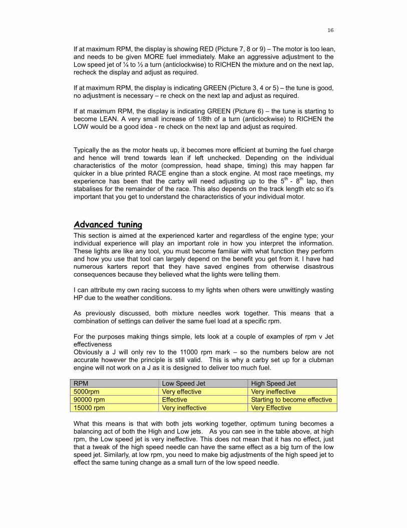
Advanced tuning This section is aimed at the experienced karter and regardless of the engine type; your individual experience will play an important role in how you interpret the information. These lights are like any tool, you must become familiar with what function they perform and how you use that tool can largely depend on the benefit you get from it. I have had numerous karters report that they have saved engines from otherwise disastrous consequences because they believed what the lights were telling them. I can attribute my own racing success to my lights when others were unwittingly wasting HP due to the weather conditions. As previously discussed, both mixture needles work together. This means that a combination of settings can deliver the same fuel load at a specific rpm. For the purposes making things simple, lets look at a couple of examples of rpm v Jet effectiveness Obviously a J will only rev to the 11000 rpm mark – so the numbers below are not accurate however the principle is still valid. This is why a carby set up for a clubman engine will not work on a J as it is designed to deliver too much fuel. RPM Low Speed Jet High Speed Jet 5000rpm Very effective Very ineffective 90000 rpm Effective Starting to become effective 15000 rpm Very ineffective Very Effective What this means is that with both jets working together, optimum tuning becomes a balancing act of both the High and Low jets. As you can see in the table above, at high rpm, the Low speed jet is very ineffective. This does not mean that it has no effect, just that a tweak of the high speed needle can have the same effect as a big turn of the low speed jet. Similarly, at low rpm, you need to make big adjustments of the high speed jet to effect the same tuning change as a small turn of the low speed needle.
17
Now for an illustration of the “balancing act”, let’s assume that your carby is set at 1/8th on the high and 1 1/2 on the low. At the end of the straight, 10800 rpm, the lights are slightly lean – the first RED LED is lit. You have 2 options, both of them are to increase fuel delivery to the motor – i.e. RICHEN But – which one!!
1. Richen the Low or 2. Richen the high.
To make a better decision, we need to now look at the lights during the slower speed corners. - If in the majority of the slow speed corners, they are indicating LEAN, giving the motor more fuel on the LOW speed needle is the answer. - If in the majority of the slow speed corners, the lights are indicating rich, the motor obviously has enough fuel down low and hence richening the high speed mixture is the answer. So you need to look at how the motor is performing over the whole track before making adjustments, keeping in mind that motors seize at HIGH rpm – and almost never at low rpm.
Extensive testing has shown that the spark plugs “seem” to read much leaner than
would normally be the case. This has proven to be no problem and in fact, the spark plug while indicating what the engine is running like during the roll down, has little
to no true indication of what the engine is running like DURING the race. To prove
this, we have performed a technique that is used in Motocross racing – A PLUG
CHOP.
This consists of driving the kart at maximum RPM down the straight, then
immediately stopping the engine as quickly as possible. This was performed with a
direct drive setup, locking the rear tyres and sliding to a stop. Inspection of the
plug will show what the true is like at high RPM and does not allow contamination
of the plug during the overly rich roll-down.
This has been performed not only on the track, but also during dyno testing. What
we found was that the plug was indicating what you would normally consider a
VERY LEAN condition – however with the same mixture settings, and allowing the
usual roll down lap, the plug reads good.
Next time you’re at the track, have a look at the exhaust of your kart on the way to
the pits. Without touching the mixture, you will be running rich – smoke puffing.
This is generally what coats the plug and gives a person that “warm fuzzy” feeling
that the motor is running on tune.
What this means, in my opinion, is karters who only read the plug after the
roll-down lap, risk interpreting their plug as too rich, while in fact, it is only due to
the excess air-fuel during the roll-down.
18
The black art of “Reading a plug”. You will undoubtedly hear karters make statements like “Look at your plug – it will tell you what your motor is doing!” Personally, I think that you have more chance of reading your stars in the paper to find out your engines tune than reading a plug. However I will let you make you mind up, but here are the facts. While this practice is true to some extent, you need to understand the reasons why it should not be relied on, especially if you are interested in tuning for maximum HP. The carbon deposits that are left behind on the sparkplug (and the internals of a motor) are what gives it its colour. These are impurities that have not burnt completely and come from 2 specific sources, the fuel and oil. There is some discolouration due to heating, however this is negligible in terms of what we are trying to achieve. ULP / PULP pump fuel contains large quantities of impurities. Some are detergents, designed to keep fuel injectors clean, some are octane promoters to reduce detonation. Unfortunately, many high octane or “premium” unleaded fuels contain more of these chemicals to achieve the higher octane ratings. If you leave your fuel container open, the higher particulates boil off leaving you with an impurity rich, low octane fuel – obviously not a desirable situation if you trying to make HP. If you have the budget, ELF offer a number of race fuels including BFK107 which is AKA approved. This is a far better fuel to use and my personal choice, especially for major events. It is almost completely combustible and leaves almost zero residue behind. While this is good for your engine, it makes reading the plug impossible and tuning lights are just about mandatory. Likewise, fully synthetic oils like Castrol TTS, are excellent race oil providing maximum protection, designed to burn completely during the combustion process. Again, this leaves very little residue behind and compounds the difficulties in reading the plug. To back up this argument, I have personally found that after 2 hours of racing, a brand new iridium plug still looks “white” on the electrode insulator. White to the point that IF I was relying solely on the look of the plug to gauge the tune, I would be concerned as to why it was so lean. The closest description of just how white a plug will look is like that of newspaper, a dirty off white. My point here is that reading a plug, at the best of times, is great if you’re working on your mower, but absolutely useless as a tuning aid especially if you want to be at the front of the pack. Fuel and Oil choice can have a large impact on what your plug tells you, and at best cannot and should not be relied on to gauge you engines performance ( Safety)
Race indications While not discounting the indications detailed above, the unit does serve a valuable second function and that is of a simple mixture monitor. If a situation occurred whereby the fuel supply was restricted or reduced (i.e. pinched fuel line, carby blockage or even as I have had myself – the fuel line rubbing through and leaking), the sensor would start to read lean. This is obviously needs to be treated
19
seriously otherwise an expensive rebuild could be just around the corner. So, during a race, it is important to understand what the lights are telling you and what to expect them to do. - Every time you snap open the throttle, the lights should indicate no change or trend towards the left – i.e. richer.
- Every time you close the throttle, especially at high Rpm, the lights should go to the right – ie leaner. If you open the throttle and the lights indicate lean, there may very well be a mixture problem – certainly add fuel to be on the safe side and keep a close eye on what happens next.
Engine Specifics.
KT100S / ARC/ Leopard /Rotax etc– These motors display different on track characteristics. Because of the different carby setups, they seem to hold more consistent tune across the rev range. Drivers have reported that the lights remain much steadier than with the J, even in the slower parts of the track. The experienced drivers can easily tune the low speed mixture needle at low to mid RPM and then the high speed mixture needle at the end of the straight. The theory is exactly the same as described above. Again, tuning lights allow you to accurately tune for “ON TRACK” conditions and not after the event, by having a stab at what the plug is indicating!
CAUTION
The Supa-Tuna is like all other sensors, be they O2, Cylinder head Temperature or
Exhaust Gas temperature. The common theme is that they are TOOLS, to assist you
in understanding what is going on in your motor. Start off with the tune that you
would normally use, and then look at the lights. Don’t blindly follow the lights (or
any other tuning aid) as things can go wrong, sensors can fail etc.
If you feel that the motor is running lean,(similar to 4 stoke – vibration and low on power), give it fuel ! Running rich is much less expensive compared to running
lean!!
20
Detailed theory of Operation There have been a number of articles written on how an O2 sensor works but unfortunately, none of these really cover the details applicable to 2 stoke race engines. The Oxygen sensor is a very simple automotive sensor, also known as an O2 sensor, lambda probe, lambda sensor, or EGO (exhaust gas oxygen) sensor. It is a small sensor inserted into the exhaust system of a petrol engine to measure the concentration of oxygen remaining in the exhaust gas.
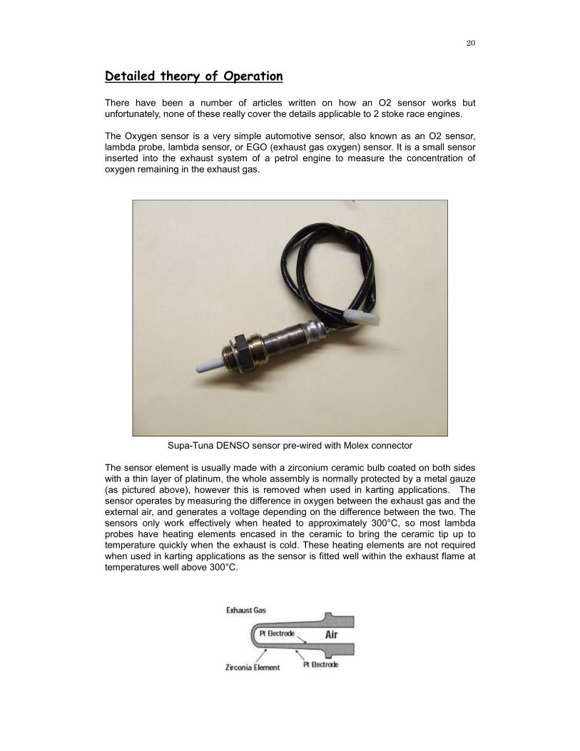
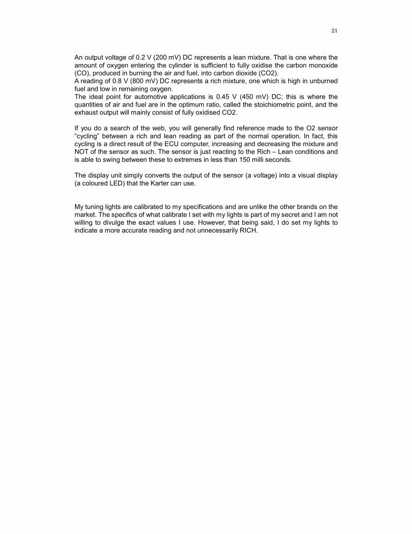
Supa-Tuna DENSO sensor pre-wired with Molex connector The sensor element is usually made with a zirconium ceramic bulb coated on both sides with a thin layer of platinum, the whole assembly is normally protected by a metal gauze (as pictured above), however this is removed when used in karting applications. The sensor operates by measuring the difference in oxygen between the exhaust gas and the external air, and generates a voltage depending on the difference between the two. The sensors only work effectively when heated to approximately 300°C, so most lambda probes have heating elements encased in the ceramic to bring the ceramic tip up to temperature quickly when the exhaust is cold. These heating elements are not required when used in karting applications as the sensor is fitted well within the exhaust flame at temperatures well above 300°C.
21
An output voltage of 0.2 V (200 mV) DC represents a lean mixture. That is one where the amount of oxygen entering the cylinder is sufficient to fully oxidise the carbon monoxide (CO), produced in burning the air and fuel, into carbon dioxide (CO2). A reading of 0.8 V (800 mV) DC represents a rich mixture, one which is high in unburned fuel and low in remaining oxygen. The ideal point for automotive applications is 0.45 V (450 mV) DC; this is where the quantities of air and fuel are in the optimum ratio, called the stoichiometric point, and the exhaust output will mainly consist of fully oxidised CO2. If you do a search of the web, you will generally find reference made to the O2 sensor “cycling” between a rich and lean reading as part of the normal operation. In fact, this cycling is a direct result of the ECU computer, increasing and decreasing the mixture and NOT of the sensor as such. The sensor is just reacting to the Rich – Lean conditions and is able to swing between these to extremes in less than 150 milli seconds. The display unit simply converts the output of the sensor (a voltage) into a visual display (a coloured LED) that the Karter can use. My tuning lights are calibrated to my specifications and are unlike the other brands on the market. The specifics of what calibrate I set with my lights is part of my secret and I am not willing to divulge the exact values I use. However, that being said, I do set my lights to indicate a more accurate reading and not unnecessarily RICH.

22
Installation
Display Unit
There are a number of possible mounting methods and personal choice becomes as important a factor, as ease of mounting. However that being said, driver comfort should be the determining factor on where the unit is positioned. The driver should be able to easily see the LED’s and importantly the shape of the LED display. The display unit is supplied with a laser cut aluminium bracket designed to attach to the steering wheel. It is recommended that the unit be attached with the supplied Velcro tape. This enables removal of the display during wet weather racing or when cleaning the kart. Position the unit, such that the LED’s do not shine directly into the drivers eyes. This becomes more important during night time use and can significantly reduce peripheral vision. It is recommended that you test the position of the unit and reposition as required by bending the aluminium plate as required. Both the Sensor (SEN) and Power (PWR) cables should be plugged into the unit with the cables positioned such that the steering wheel can be moves without putting any strain in the unit.
O2 Sensor
Almost all Oxygen sensor use stainless steel wires sheathed in high temperature insulation. Stainless steel is typically difficult to join via normal soldering techniques and is also known to cause premature failure of the sensor wire. As a result, the SUPA-TUNA system uses crimp terminations and high quality Molex plugs.
23
Caution
There are a number of precautions that you must take when handling the sensor.
1. NEVER touch the ceramic tip, silicon and oil from your fingers can contaminate
the sensor element.
2. NEVER drop or bump the ceramic tip. The element is very fragile and can be easily damaged through rough treatment.
3. NEVER use silicon sealers on the inlet ( carby gaskets, phenolic spacer etc) or
exhaust flange.
4. NEVER use leaded fuel. Lead will contaminate the sensor.
You will notice that my sensors are significantly cheaper than any other manufacturer. Sensors are consumable, meaning that like spark plugs, they don’t last forever. I believe that keeping the cost of the sensors down, karters are more willing to replace a suspect sensor rather than persevere with an inaccurate reading and risk damage to a motor. Alternately, if you chose to purchase your own sensor, they can also be sourced through any fuel injection outlet, Repco, Super cheap etc. for between $90 – 120. Almost any universal 2 (or 4) wire sensor will be suitable, but they must be isolated design not earthed.
O2 Sensor Signal Wire
The display unit is connected to the sensor via a light and flexible wire ideally suited to the high vibration environment of Karting. The plug on the end of this wire is crimped and soldered to increase not only the strength of the termination, but also the signal quality. Again, high quality Molex connectors are used for longevity and ease of connection. With the display unit positioned on the steering wheel, secure the signal wire with a loop, loose enough to allow the wheel to turn fully in both directions without pulling on the display. Any excess cable should be looped and tied securely to the kart. It is recommended that this loop be positioned away from the ground – ideally on the steering column. Magnetic strips can cause interference with the LED display, resulting in a ‘blip” of lights as you pass over them. Caution The sensor lead should be routed as far as possible from the ignition and spark
plug wires. Kart engines typically produce very high voltages and this can damage
the unit. The sensor wire should typically be run down the left hand side of the
kart away from the motor.
24
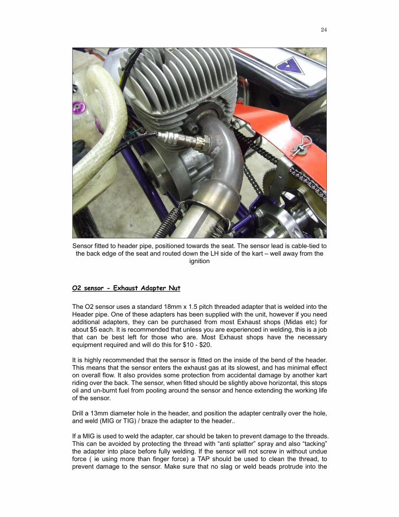
Sensor fitted to header pipe, positioned towards the seat. The sensor lead is cable-tied to the back edge of the seat and routed down the LH side of the kart – well away from the
ignition
O2 sensor - Exhaust Adapter Nut
The O2 sensor uses a standard 18mm x 1.5 pitch threaded adapter that is welded into the Header pipe. One of these adapters has been supplied with the unit, however if you need additional adapters, they can be purchased from most Exhaust shops (Midas etc) for about $5 each. It is recommended that unless you are experienced in welding, this is a job that can be best left for those who are. Most Exhaust shops have the necessary equipment required and will do this for $10 - $20. It is highly recommended that the sensor is fitted on the inside of the bend of the header. This means that the sensor enters the exhaust gas at its slowest, and has minimal effect on overall flow. It also provides some protection from accidental damage by another kart riding over the back. The sensor, when fitted should be slightly above horizontal, this stops oil and un-burnt fuel from pooling around the sensor and hence extending the working life of the sensor. Drill a 13mm diameter hole in the header, and position the adapter centrally over the hole, and weld (MIG or TIG) / braze the adapter to the header.. If a MIG is used to weld the adapter, car should be taken to prevent damage to the threads. This can be avoided by protecting the thread with “anti splatter” spray and also “tacking” the adapter into place before fully welding. If the sensor will not screw in without undue force ( ie using more than finger force) a TAP should be used to clean the thread, to prevent damage to the sensor. Make sure that no slag or weld beads protrude into the
25
header pipe, if they do, get rid of them as they will not only impede gas flow, but can also set up eddy currents that buffer the sensor giving you false readings. Testing has also shown that the size of the hole is not important, however a slightly larger hole does prevent the sensor from being damaged when installing into the header. As long as the hole is central to the adapter, a 13mm hole is sufficient. KT100J – Some people have experienced better performance by positioning the nut as close to the flex end of the header pipe as possible. This seems to be due to the gasses being more fluid at this point and not as “pulse-like”. All sensors that I fit now, I position 20mm towards the flex end from the centerline of the curve – this I have found is an ideal compromise and offers best all round performance. Kt100S / Leopard – Position the nut such that the sensor in the centre of the curve of the header. Some karts may require the sensor to be positioned at a slight angle to clear any seat stays used. If this is the case, allow a minimum of 15 – 20mm clearance. Rotax – The nut is welded into the body of the exhaust pipe, 100 – 150mm from the motor end. Comer – The nut is welded into the body of the muffler, position is generally not critical. The most suitable position is in the top RH corner while looking at the exhaust pipe side of the muffler.
26
Power selection The Supa-Tuna V4 has been designed to offer the user multiple power options.
1. Automatic ON-OFF - using supplied AA Battery Unit This method uses a sense wire that is run along side the sparkplug lead, and allows the display to automatically turn on as soon as the engine is started. It will also turn itself off as soon as the engine stops firing.
2. Automatic ON-OFF - Using onboard lead acid battery
As detailed above, however an optional battery lead can be supplied to connect the unit to the onboard 12V lead acid battery as use on TAG karts (i.e. Leopard and Rotax powered karts).
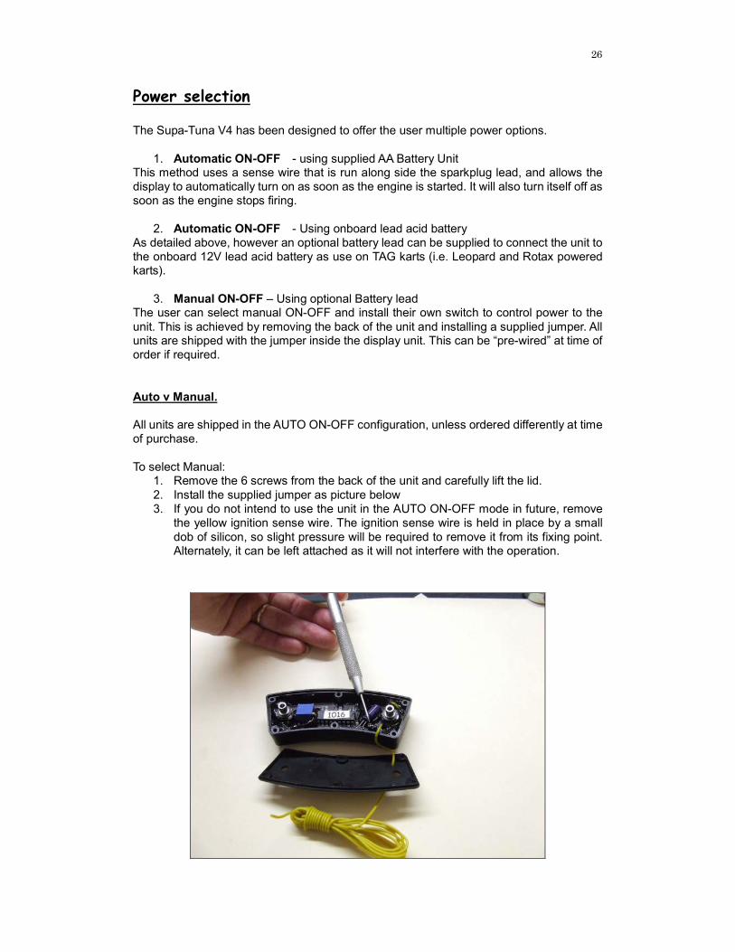
3. Manual ON-OFF – Using optional Battery lead The user can select manual ON-OFF and install their own switch to control power to the unit. This is achieved by removing the back of the unit and installing a supplied jumper. All units are shipped with the jumper inside the display unit. This can be “pre-wired” at time of order if required. Auto v Manual. All units are shipped in the AUTO ON-OFF configuration, unless ordered differently at time of purchase. To select Manual:
1. Remove the 6 screws from the back of the unit and carefully lift the lid. 2. Install the supplied jumper as picture below 3. If you do not intend to use the unit in the AUTO ON-OFF mode in future, remove
the yellow ignition sense wire. The ignition sense wire is held in place by a small dob of silicon, so slight pressure will be required to remove it from its fixing point. Alternately, it can be left attached as it will not interfere with the operation.
27
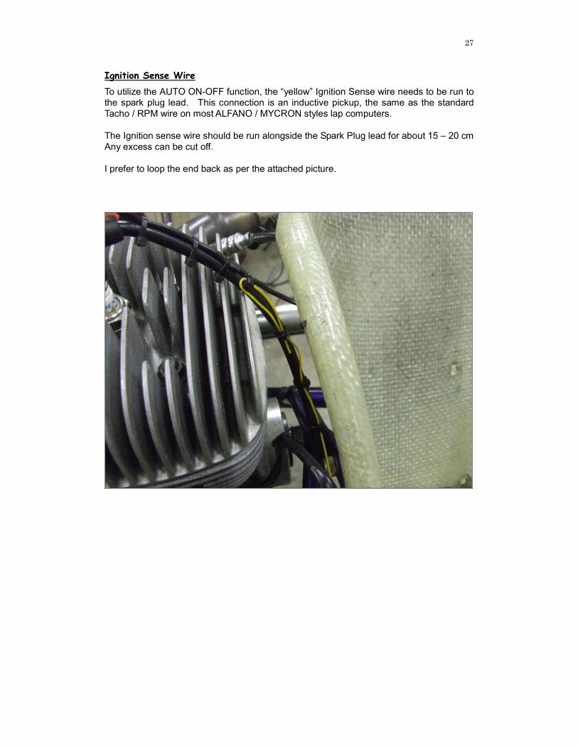
Ignition Sense Wire
To utilize the AUTO ON-OFF function, the “yellow” Ignition Sense wire needs to be run to the spark plug lead. This connection is an inductive pickup, the same as the standard Tacho / RPM wire on most ALFANO / MYCRON styles lap computers. The Ignition sense wire should be run alongside the Spark Plug lead for about 15 – 20 cm Any excess can be cut off. I prefer to loop the end back as per the attached picture.

28
The battery unit The Battery
The Supa-Tuna V4 uses a standard AA battery. Rechargeable AA’s can be used, but you may get a reduced useable time between charges, as rechargeable batteries do not have the same capacity as a standard heavy duty alkaline.
Note: Because the unit turns itself on and off, battery life has been extended and
in excess of 12 hours use is typically achieved. Batteries do have a finite life, and
unfortunately sometimes they sit in shops well past their expected shelf life.
As pictured, a small red LED has been included in the design of the battery unit. This LED will illuminate when a good battery is installed and the display is running. Changing the Battery The end of the battery unit unscrews and the AA battery can be replaced. The unit has been designed so that accidentally inserting the battery in the wrong way, will not damage the unit. The battery cable is connected to the connector labeled PWR, accidental insertion into the wrong connector will not result in any damage.
29
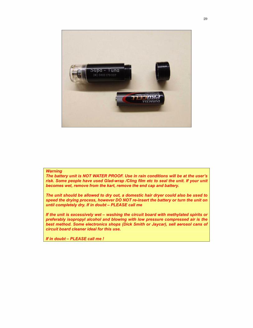
Warning
The battery unit is NOT WATER PROOF. Use in rain conditions will be at the user’s
risk. Some people have used Glad-wrap /Cling film etc to seal the unit. If your unit
becomes wet, remove from the kart, remove the end cap and battery.
The unit should be allowed to dry out, a domestic hair dryer could also be used to
speed the drying process, however DO NOT re-insert the battery or turn the unit on
until completely dry. If in doubt – PLEASE call me
If the unit is excessively wet – washing the circuit board with methylated spirits or preferably isopropyl alcohol and blowing with low pressure compressed air is the
best method. Some electronics shops (Dick Smith or Jaycar), sell aerosol cans of
circuit board cleaner ideal for this use.
If in doubt – PLEASE call me !
30
O2 Sensors - Do they wear out? As an oxygen sensor ages, contaminants from normal combustion and oil ash accumulate on the sensing element. This reduces the sensor's ability to respond quickly to changes in the air/fuel mixture. The sensor slows down and becomes "sluggish". At the same time, the sensor's output voltage may not be as high as it once was, giving the false impression that the air/fuel mixture is leaner than it actually is. The can result in the karter, tuning a richer-than-required air/fuel mixture. Generally speaking, this is a better scenario and “safer” than if the sensor was to indicate rich while in fact being too lean. The worst case means that you will be feeding the motor too much fuel and hence slow – however unlikely to have a motor to repair !! Over time, the situation will get worse, ultimately requiring the sensor to be replaced to restore peak tuning performance. How long will this take? Well, unfortunately that’s like asking “How long is a piece of string?”. We have been running the same sensor on a dyno for over 12 months, this includes running in motors with the excessively rich mixtures required. This sensor is still performing fine. At a rough guess, a sensor should last at least a year, depending on the amount of racing that you do. Obviously the header of a Kt100S is far more arduous than any car would be so you should expect to replace the sensor as part of you kart consumables. That being said, I have had 2 sensors that lasted only 2 meetings each, and they were both brand new $140 Bosch sensors. I now will only use Denso sensors and have proven them to be accurate and a good life span. The latest sensors are also manufactured to include a coating that limits contamination, further extending their useable life.
31
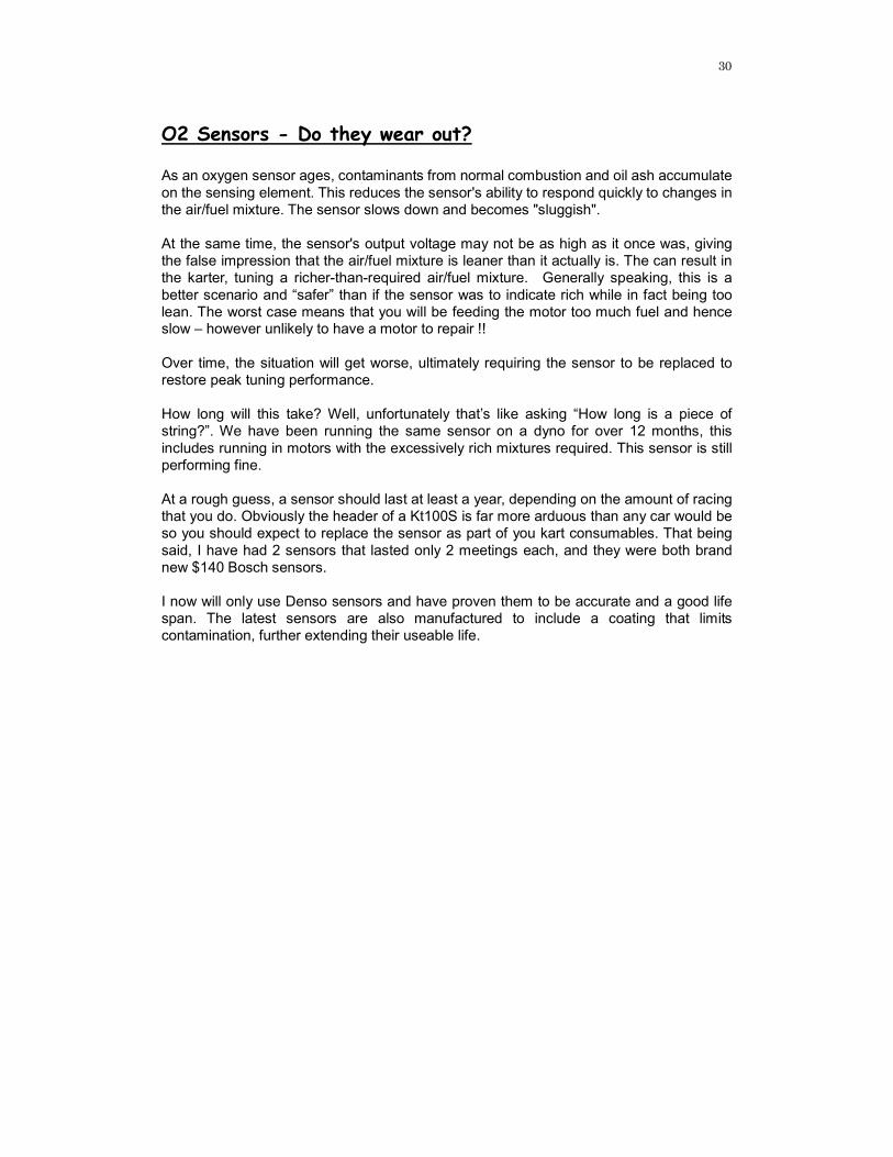
This picture shows damage to the sensor element. On removal from the motor, the protective eggshell like ceramic coating surrounding the tip of the sensor was flaking away. This particular example was the result of damage when installing the sensor in the header pipe through rough treatment. – This sensor needs to be replaced.
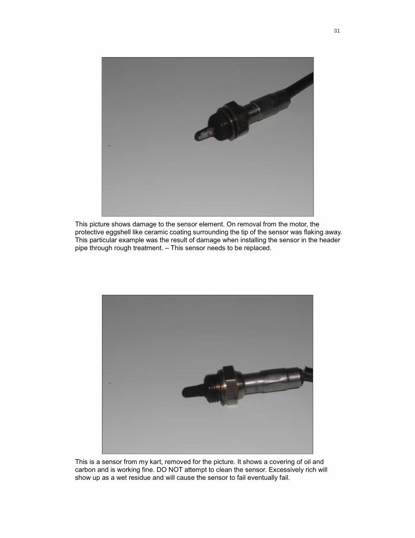
This is a sensor from my kart, removed for the picture. It shows a covering of oil and carbon and is working fine. DO NOT attempt to clean the sensor. Excessively rich will show up as a wet residue and will cause the sensor to fail eventually fail.