super duty™ conveyor installation manual · conveyor installation procedures ... repeat the same...
TRANSCRIPT

© Motor City Wash Works, Inc. 48285 Frank, Wixom Michigan 48393 U.S.A. Phone: 248.313.0272 ▪ Fax: 248. 313.0271 VERSION: 02-20-14 www.motorcitywashworks.com 1
SUPER DUTY™ CONVEYOR INSTALLATION MANUAL
Equipment Features:
Air Assist Take Up 1/2” Top Deck, 3/8” Structure: The Toughest of the Industry! Anti-Jamming Air Dollie Up System X-458 52000LB Chain Tensile Strength Manual Dollie Up System Standard Quiet Operation: NO BANGING Redundant Trap Door System for Added Safety (we can never be too careful!) Direct Drive Héco Gear Reducer Electric and Hydraulic Drive Available
Equipment Requirements and Specifications:
TABLE OF CONTENTS Equipment Specifications Page: 1 Suggested Tools and Installation Materials Page: 2 Installation Procedures Page: 3 Pneumatic Installation Page: 21 Electrical Installation Page: 23 Star-Up Procedures Page: 30
ELECTRIC DRIVE5HP HYDRAULIC DRIVE
208VAC – 17.5FLA - 3PH 460VAC – 7.6FLA - 3PH
UL® RECOGNIZED, CSA CERTIFIED, CE MARK, IEC IP 55
N/A
ELECTRICAL ROLLER UP AIR PANEL: 24 or 120VAC
PULSE SENSOR and/or ROLLER COUNT SENSOR: 24-250V AC/DC
HYDRAULIC N/A
FROM 3.5 @ 60CPH
to 14GPM @ 200CPH (2) 1/2”JIC Fittings
PNEUMATICS
2 SCFM
(4) 3/8" O.D. PUSH-IN FITTINGS FOR TAKE-UP AND ROLLER-UP CYLINDERS (1) 3/8" O.D. PUSH-IN FITTINGS FOR AIR PANEL MAIN AIR FEED
CAR WASH CONTROLLER
(2) OUTPUT FUNCTIONS (ROLLER UP and CONVEYOR RUN)
(2) INPUT FUNCTIONS (LOW AIR and TOO LONG CHAIN)
WEIGHT
5FT ENTRANCE SECTION: 600LBS (APROX) 10 FT CENTER SECTION: 800LBS (APROX)
5FT EXIT SECTION: 575LBS (APROX) ACCESSORIES (CHAIN, ROLLER, ECT): VARIES
© Motor City Wash Works, Inc. 48285 Frank, Wixom Michigan 48393 U.S.A. Phone: 248.313.0272 ▪ Fax: 248. 313.0271 VERSION: 02-20-14 www.motorcitywashworks.com 2
Equipment Dimensions:
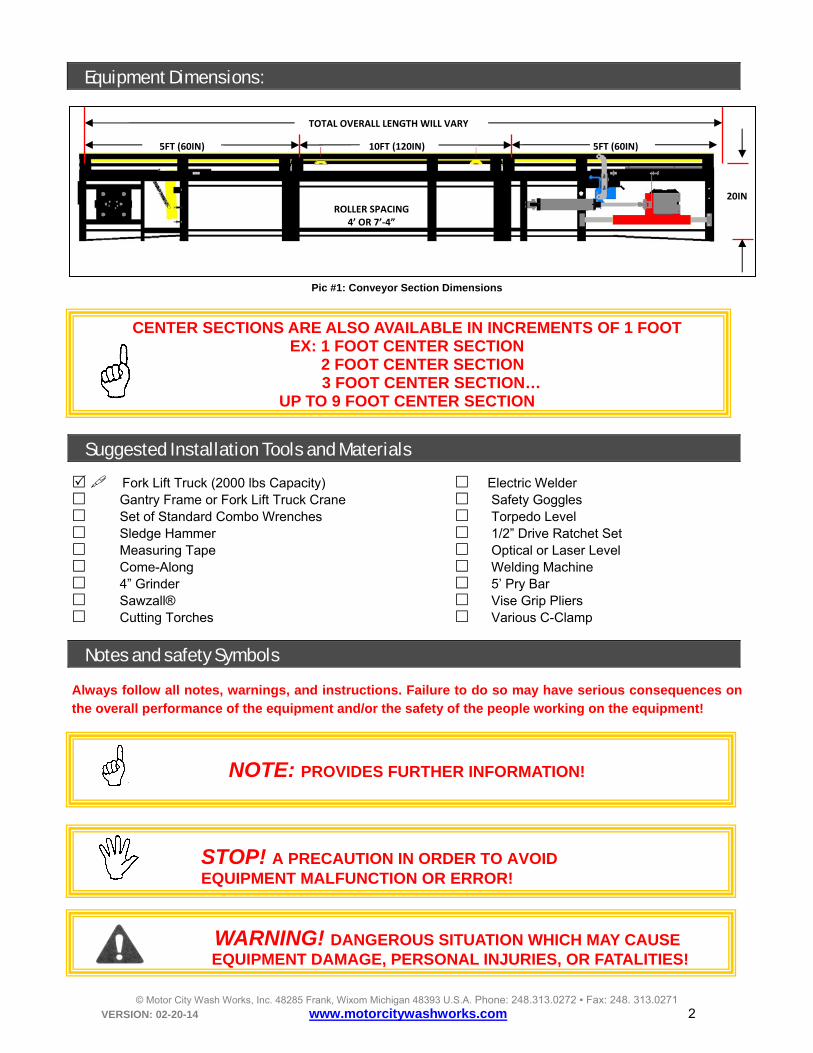
Pic #1: Conveyor Section Dimensions
CENTER SECTIONS ARE ALSO AVAILABLE IN INCREMENTS OF 1 FOOT EX: 1 FOOT CENTER SECTION 2 FOOT CENTER SECTION
3 FOOT CENTER SECTION… UP TO 9 FOOT CENTER SECTION
Suggested Installation Tools and Materials
Fork Lift Truck (2000 lbs Capacity) Electric Welder Gantry Frame or Fork Lift Truck Crane Safety Goggles Set of Standard Combo Wrenches Torpedo Level Sledge Hammer 1/2” Drive Ratchet Set Measuring Tape Optical or Laser Level Come-Along Welding Machine 4” Grinder 5’ Pry Bar Sawzall® Vise Grip Pliers Cutting Torches Various C-Clamp
Notes and safety Symbols
Always follow all notes, warnings, and instructions. Failure to do so may have serious consequences on the overall performance of the equipment and/or the safety of the people working on the equipment!
NOTE: PROVIDES FURTHER INFORMATION!
WARNING! DANGEROUS SITUATION WHICH MAY CAUSE EQUIPMENT DAMAGE, PERSONAL INJURIES, OR FATALITIES!
STOP! A PRECAUTION IN ORDER TO AVOID EQUIPMENT MALFUNCTION OR ERROR!
ROLLER SPACING4’ OR 7’‐4”
5FT (60IN) 10FT (120IN) 5FT (60IN)
TOTAL OVERALL LENGTH WILL VARY
20IN
© Motor City Wash Works, Inc. 48285 Frank, Wixom Michigan 48393 U.S.A. Phone: 248.313.0272 ▪ Fax: 248. 313.0271 VERSION: 02-20-14 www.motorcitywashworks.com 3
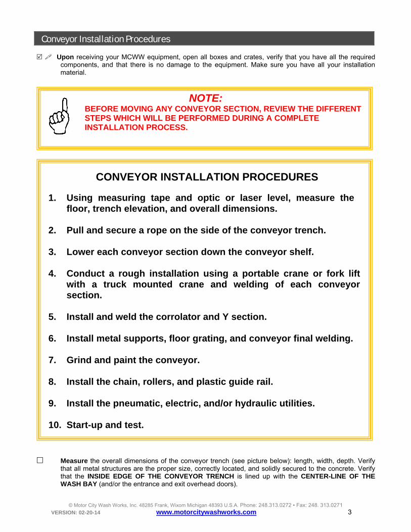
Conveyor Installation Procedures Upon receiving your MCWW equipment, open all boxes and crates, verify that you have all the required
components, and that there is no damage to the equipment. Make sure you have all your installation material.
NOTE: BEFORE MOVING ANY CONVEYOR SECTION, REVIEW THE DIFFERENT STEPS WHICH WILL BE PERFORMED DURING A COMPLETE INSTALLATION PROCESS.
CONVEYOR INSTALLATION PROCEDURES
1. Using measuring tape and optic or laser level, measure the floor, trench elevation, and overall dimensions.
2. Pull and secure a rope on the side of the conveyor trench.
3. Lower each conveyor section down the conveyor shelf.
4. Conduct a rough installation using a portable crane or fork lift
with a truck mounted crane and welding of each conveyor section.
5. Install and weld the corrolator and Y section.
6. Install metal supports, floor grating, and conveyor final welding.
7. Grind and paint the conveyor.
8. Install the chain, rollers, and plastic guide rail.
9. Install the pneumatic, electric, and/or hydraulic utilities.
10. Start-up and test.
Measure the overall dimensions of the conveyor trench (see picture below): length, width, depth. Verify
that all metal structures are the proper size, correctly located, and solidly secured to the concrete. Verify that the INSIDE EDGE OF THE CONVEYOR TRENCH is lined up with the CENTER-LINE OF THE WASH BAY (and/or the entrance and exit overhead doors).

© Motor City Wash Works, Inc. 48285 Frank, Wixom Michigan 48393 U.S.A. Phone: 248.313.0272 ▪ Fax: 248. 313.0271 VERSION: 02-20-14 www.motorcitywashworks.com 4
1" (254mm)TYP
22" (5588 mm)MINIMUM
20" [508mm]
40" [1016mm]
Pic #2: Conveyor Trench Section
NOTE: THE OVERALL LENGTH OF THE CONVEYOR TRENCH HAS TO BE EQUAL TO:
THE CONVEYOR LENGTH + 6 INCHES UP TO 130FT TOTAL 131 AND UP ADD 12” TOTAL
EXAMPLE #1: 100’ CONVEYOR = TRENCH LENGTH 100’-6” EXAMPLE #2: 140’ CONVEYOR = TRENCH LENGTH 141’
20"
40"
30"
3112"
30"
4612"
64"
CV LENGTH + 1" PER 10FEET SECTION
Pic #4: Conveyor and Corrolator Overall Dimensions
NOTE: DO NOT FORGET TO MEASURE THE CORROLATOR TRENCH.
Using a chalk line, snap a first line in the conveyor trench from entrance to exit IN THE CENTER OF THE
SHELF. Snap a second line parallel to the conveyor trench ON PASSENGER’S SIDE AND 60” AWAY FROM THE FIRST LINE (see Picture #5 below). Starting at the beginning of the wash, mark both lines EVERY 5 FEET.
METAL STRUCTURES

© Motor City Wash Works, Inc. 48285 Frank, Wixom Michigan 48393 U.S.A. Phone: 248.313.0272 ▪ Fax: 248. 313.0271 VERSION: 02-20-14 www.motorcitywashworks.com 5
0" 5' 85' 90' 95' 100'
60"
Pic #5: Chalk Line
Using an OPTICAL LEVEL or a LASER LEVEL (see picture #6), measure the elevation of the floor and the conveyor trench shelf EVERY 5 FEET and record on a chart similar to the one shown in picture #7 below. Archive the results and keep it for your records.
0'5'10'15'20'85'9095100'
60"
Pic #6: Measuring Floor Elevation
Pic #7: Recording Data
© Motor City Wash Works Inc. 48285 Frank, Wixom Michigan 48393 U.S.A. Phone: 248.313.0272 ▪ Fax: 248. 313.0271
LOCATION NAME: DATE:
CONVEYOR LENGTH: FEET TECH NAME:
DISTANCE (FT) SHELF ELEVATION (IN) FLOOR ELEVATION (IN)
0 → 72 50
5 → 72 50‐1/8
→
→
→
→
→
→
→

© Motor City Wash Works, Inc. 48285 Frank, Wixom Michigan 48393 U.S.A. Phone: 248.313.0272 ▪ Fax: 248. 313.0271 VERSION: 02-20-14 www.motorcitywashworks.com 6
IMPORTANT NOTE:
IF YOUR CONVEYOR IS A REAR WHEEL PUSH: OVERALL ELEVATION OF THE CONVEYOR WILL BE 1” ABOVE FLOOR LEVEL, TAKEN 60” AWAY TOWARD PASSENGER’S SIDE (see picture #8).
IF YOUR CONVEYOR IS A FRONT WHEEL PULL: OVERALL ELEVATION OF THE CONVEYOR WILL BE 1” BELOW FLOOR LEVEL, TAKEN 60” AWAY TOWARD PASSENGER’S SIDE (see picture #9).
60"
REAR WHEEL PUSH:THE CONVEYOR IS 1"
HIGHER THAN THE PASSENGER SIDE
70"(EXAMPLE) 71"
(EXAMPLE)
1"
60"
FRONT WHEEL PULL:THE CONVEYOR IS 1"
LOWER THAN THE PASSENGER SIDE
72"(EXAMPLE) 71"
(EXAMPLE)
1"
Pic #8: Rear Wheel Push Pic #9: Front Wheel Pull
Pull a rope along the conveyor trench and secure 1” AWAY FROM THE TRENCH EDGE AND 1” TO 2” ABOVE THE FLOOR (see picture below).
1"
Pic #10: Pull String
Drop all the conveyor sections in the trench onto the approximate location on the conveyor shelf. Secure together the ENTRANCE SECTION WITH ONE 10’ SECTION using the supplied 1/2-13
fasteners. Lined up and weld tack together.
ROPE

© Motor City Wash Works, Inc. 48285 Frank, Wixom Michigan 48393 U.S.A. Phone: 248.313.0272 ▪ Fax: 248. 313.0271 VERSION: 02-20-14 www.motorcitywashworks.com 7
Using a A-FRAME CRANE (see picture #11 and support document section for A-Frame DWG ) or a fork lift mounted crane (see picture #12) and a CHAIN HOIST (see picture #13 below), raise the first section and position the entrance side AGAINST THE ENTRANCE TRENCH WALL and 1” AWAY FROM THE DRIVER’S SIDE TRENCH WALL. Use the rope to keep each section parallel to the trench wall and about 1” away from the trench wall.
Pic #11: A-Frame Crane
Pic #12: Fork Lift Truck Mounted Crane
Level the section from left to right (see picture #13) and spot weld the entrance side of the section FLUSH TO THE TOP OF THE METAL ANGLE AT THE ENTRANCE OF THE TRENCH (Picture #14).
Pic #13: Level Section (View from the Entrance) Pic #14: Weld Entrance
NOTE: IF SPACE IS NEEDED BETWEEN THE CONVEYOR FRAME AND THE ENTRANCE WALL OF THE CONVEYOR TRENCH, YOU MAY WELD A 2” PIECE OF STEEL BETWEEN THE CONVEYOR AND THE TRENCH ANGLE.
LEVEL
AGAINST ENTRANCE
WALL
AGAINST ENTRANCE
WALL
CHAIN HOIST KEEP GAP ABOUT 1IN
© Motor City Wash Works, Inc. 48285 Frank, Wixom Michigan 48393 U.S.A. Phone: 248.313.0272 ▪ Fax: 248. 313.0271 VERSION: 02-20-14 www.motorcitywashworks.com 8
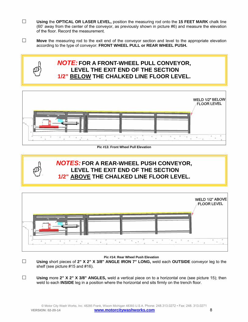
Using the OPTICAL OR LASER LEVEL, position the measuring rod onto the 15 FEET MARK chalk line (60’ away from the center of the conveyor, as previously shown in picture #6) and measure the elevation of the floor. Record the measurement.
Move the measuring rod to the exit end of the conveyor section and level to the appropriate elevation
according to the type of conveyor: FRONT WHEEL PULL or REAR WHEEL PUSH.
NOTE: FOR A FRONT-WHEEL PULL CONVEYOR,
LEVEL THE EXIT END OF THE SECTION 1/2” BELOW THE CHALKED LINE FLOOR LEVEL.
Pic #13: Front Wheel Pull Elevation
NOTES: FOR A REAR-WHEEL PUSH CONVEYOR,
LEVEL THE EXIT END OF THE SECTION 1/2” ABOVE THE CHALKED LINE FLOOR LEVEL.
Pic #14: Rear Wheel Push Elevation
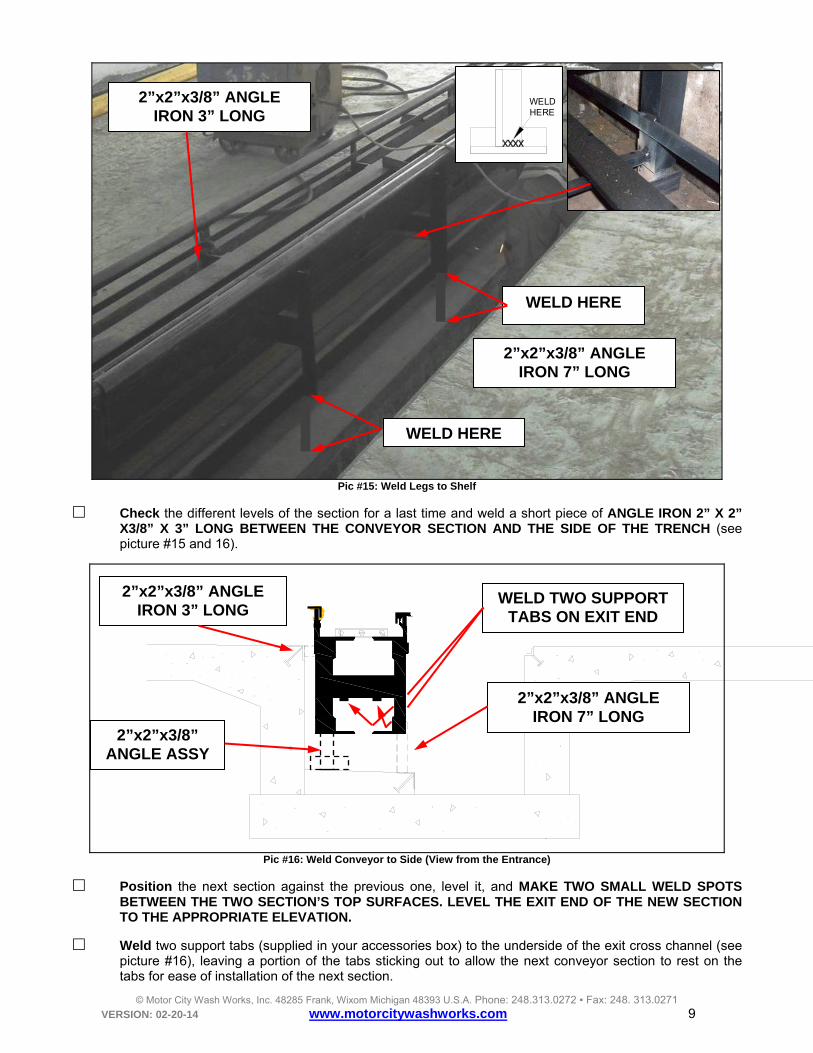
Using short pieces of 2” X 2” X 3/8" ANGLE IRON 7” LONG, weld each OUTSIDE conveyor leg to the shelf (see picture #15 and #16).
Using more 2” X 2” X 3/8" ANGLES, weld a vertical piece on to a horizontal one (see picture 15); then weld to each INSIDE leg in a position where the horizontal end sits firmly on the trench floor.
© Motor City Wash Works, Inc. 48285 Frank, Wixom Michigan 48393 U.S.A. Phone: 248.313.0272 ▪ Fax: 248. 313.0271 VERSION: 02-20-14 www.motorcitywashworks.com 9
Pic #15: Weld Legs to Shelf
Check the different levels of the section for a last time and weld a short piece of ANGLE IRON 2” X 2” X3/8” X 3” LONG BETWEEN THE CONVEYOR SECTION AND THE SIDE OF THE TRENCH (see picture #15 and 16).
Pic #16: Weld Conveyor to Side (View from the Entrance)
Position the next section against the previous one, level it, and MAKE TWO SMALL WELD SPOTS BETWEEN THE TWO SECTION’S TOP SURFACES. LEVEL THE EXIT END OF THE NEW SECTION TO THE APPROPRIATE ELEVATION.
Weld two support tabs (supplied in your accessories box) to the underside of the exit cross channel (see picture #16), leaving a portion of the tabs sticking out to allow the next conveyor section to rest on the tabs for ease of installation of the next section.
2”x2”x3/8” ANGLE IRON 7” LONG
WELD HERE
WELD HERE
2”x2”x3/8” ANGLE IRON 3” LONG
2”x2”x3/8” ANGLE IRON 7” LONG
2”x2”x3/8” ANGLE IRON 3” LONG
WELDHERE
2”x2”x3/8” ANGLE ASSY
WELD TWO SUPPORT TABS ON EXIT END

© Motor City Wash Works, Inc. 48285 Frank, Wixom Michigan 48393 U.S.A. Phone: 248.313.0272 ▪ Fax: 248. 313.0271 VERSION: 02-20-14 www.motorcitywashworks.com 10
Repeat the same procedure (previously shown in picture #15 and #16) and install short pieces of 2” X 2” X 1/4" ANGLE IRON 7” LONG, and weld each conveyor leg to the shelf. Repeat the same for the side of the conveyor using the 3” long pieces.
Position the THIRD section against the previous one, level it (as previously shown in picture #13), and SPOT WELD THE TWO SECTIONS TOGETHER. Then, LEVEL THE EXIT END OF THE NEW SECTION TO THE SAME ELEVATION as THE FLOOR ON PASSENGER’S SIDE. Weld each leg to the shelf as well as the side to the trench.
IF YOUR CONVEYOR IS A FRONT WHEEL PULL: OVERALL ELEVATION OF THE CONVEYOR WILL BE 1” BELOW FLOOR LEVEL TAKEN 60” AWAY TOWARD PASSENGER’S SIDE (see Picture #19). IF YOUR CONVEYOR IS A REAR WHEEL PUSH: OVERALL ELEVATION OF THE CONVEYOR WILL BE 1” ABOVE FLOOR LEVEL TAKEN 60” AWAY TOWARD PASSENGER’S SIDE (see Picture #20).
60"
FRONT WHEEL PULL:THE CONVEYOR IS 1"
LOWER THAN THE PASSENGER SIDE
72"(EXAMPLE) 71"
(EXAMPLE)
1"
60"
REAR WHEEL PUSH:THE CONVEYOR IS 1"
HIGHER THAN THE PASSENGER SIDE
70"(EXAMPLE) 71"
(EXAMPLE)
1"
Pic #19: Front Wheel Pull Pic #20: Rear Wheel Push
Continue adding additional sections while maintaining the overall elevation up to THE TWO LAST CONVEYOR SECTIONS.
Add the previous to last section to the existing conveyor and LEVEL THE EXIT END 1/2” ABOVE OR BELOW FLOOR LEVEL, DEPENDING IF THE CONVEYOR IS TO RAISE OR LOWER IN ORDER TO MEET THE FLOOR ELEVATION AT THE EXIT END (see picture #21 and #22).
1" BELOW FLOOR LEVELAT
FLOOR LEVELAT
FLOOR LEVEL
Pic #21: Front Wheel Pull Conveyor
1" ABOVE FLOOR LEVELAT
FLOOR LEVELAT
FLOOR LEVEL
Pic #22: Rear Wheel Push Conveyor
© Motor City Wash Works, Inc. 48285 Frank, Wixom Michigan 48393 U.S.A. Phone: 248.313.0272 ▪ Fax: 248. 313.0271 VERSION: 02-20-14 www.motorcitywashworks.com 11
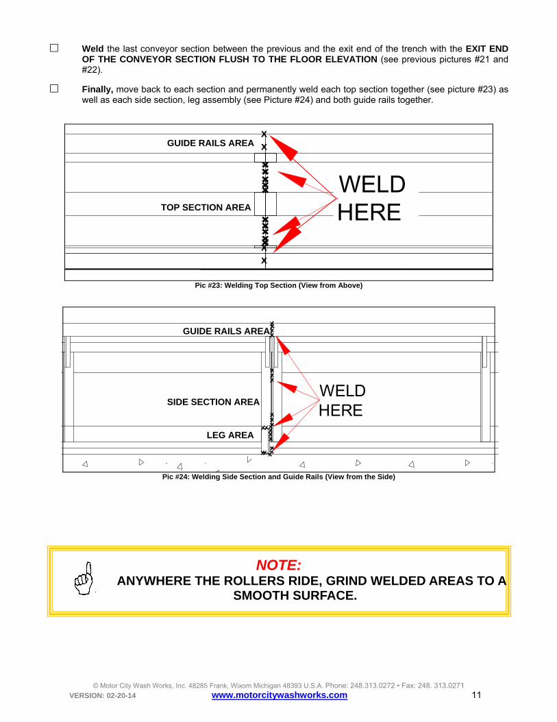
Weld the last conveyor section between the previous and the exit end of the trench with the EXIT END OF THE CONVEYOR SECTION FLUSH TO THE FLOOR ELEVATION (see previous pictures #21 and #22).
Finally, move back to each section and permanently weld each top section together (see picture #23) as well as each side section, leg assembly (see Picture #24) and both guide rails together.
WELDHERE
Pic #23: Welding Top Section (View from Above)
WELDHERE
Pic #24: Welding Side Section and Guide Rails (View from the Side)
NOTE:
ANYWHERE THE ROLLERS RIDE, GRIND WELDED AREAS TO A SMOOTH SURFACE.
TOP SECTION AREA
GUIDE RAILS AREA
LEG AREA
SIDE SECTION AREA
GUIDE RAILS AREA x x
x x

© Motor City Wash Works, Inc. 48285 Frank, Wixom Michigan 48393 U.S.A. Phone: 248.313.0272 ▪ Fax: 248. 313.0271 VERSION: 02-20-14 www.motorcitywashworks.com 12
Gear-Motor and Pulse Sensor Installation Procedure Your Motor City Super Duty™ drive unit comes in two different versions: HYDRAULIC or ELECTRIC drive.
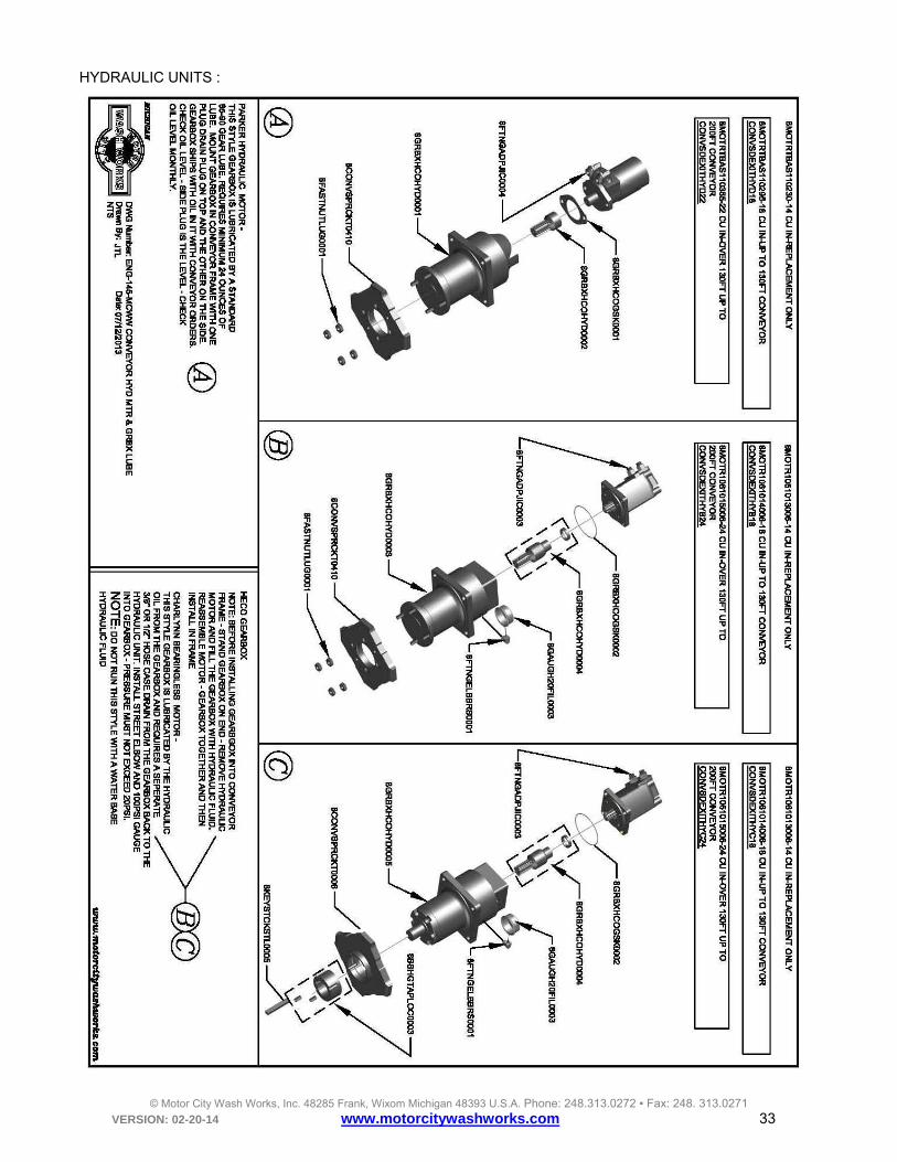
Hydraulic Drive: The hydraulic drive version is offered in three configurations:
1. SEALED HYDRAULIC MOTOR with a FLANGED OUTPUT SHAFT HECO GEAR-REDUCER filled and lubricated with Gearlube (see picture #25 below).
2. BEARING-LESS HYDRAULIC MOTOR also with a FLANGED OUTPUT SHAFT HECO GEAR-
REDUCER lubricated with hydraulic fluid coming from the motor’s opened seal (See Picture #26 below). This arrangement requires a SEPARATE DRAIN LINE plumbed from the GEAR-REDUCER CASE DRAIN back to the hydraulic unit.
3. Finally, a BEARING-LESS HYDRAULIC MOTOR with a STRAIGHT KEYED OUTPUT SHAFT HECO GEAR-REDUCER also lubricated with hydraulic fluid coming from the motor (See Picture #27 below). This arrangement also requires a DRAIN LINE.
Pic #25: Sealed Motor Pic #26: Bearing-less Motor (open seal) Pic #27: Bearing-less Motor (open seal) with Gearlube HECO Unit with Hydrous-Lube HECO Unit with Hydrous-Lube HECO Unit and (Requires a Case drain) Straight Keyed Output Shaft (also Requires a Case drain!)
Locate the gear-motor assembly and verify that the Heco gear reducer is filled with gearlube oil. Position the assembly on a flat surface, remove the oil level plug (see picture #28) and verify that there is oil overflowing from the gear case.
Pic #28: Hydraulic Gear-Motor Assembly
OIL LEVEL PLUG

© Motor City Wash Works, Inc. 48285 Frank, Wixom Michigan 48393 U.S.A. Phone: 248.313.0272 ▪ Fax: 248. 313.0271 VERSION: 02-20-14 www.motorcitywashworks.com 13
If the oil is not overflowing, your gear-motor may have been shipped w/o oil and you will have to FILL THE GEAR-REDUCER WITH GEARLUBE OIL! To do so, position the gear-motor assembly vertically, with the motor on top, and separate the motor from the gear-reducer by removing the two 1/2-13 bolts (see Picture #29) securing the motor to the gear-reducer.
Pic #29: Separate Motor from Gear-Reducer Pic #30: Fill with 24OZ of Gearlube
Fill the gear-reducer gear case with 20-24 OUNCES with SAE 80W or 90W GEARLUBE oil that meets API-GL5 and APIMT1 SERVICE or fill until oil is over flowing from the oil level port. The oil should be readily available at your local automotive store or lubricant dealer or from your local MCWW Reseller.
When using a BEARING-LESS HYDRAULIC MOTOR, separate the motor from the gear-reducer and filled the gear case to the maximum with the same hydraulic fluid use to drive the motor. Using ISO 32, 46 or 68 hydraulic oil depending on the area where the conveyor is located (warm climates versus cold climates).
Locate the drive sprocket and secure to the output flange (or shaft).
Mount to the exit section of the conveyor (as shown in picture #31 or 32). The gear-motor assembly can
be mounted on the DRIVER’S SIDE or on the PASSENGER’S SIDE of the conveyor trench. If you decide to mount it on the PASSENGER’S SIDE, you will have to relocate the pulse encoder sensor to the driver side (the sensor is factory mounted on the passenger side). Finally, mount the ENCODER to the sprocket (see picture #33). Verify that the PULSE ENCODER SENSOR is positioned between where there is a gap between 1/8 and 1/4 inches from the encoder head bolts to the sensor’s sensing area.
Pic #31: D/S Mounting Pic #32: P/S Mounting Pic #33: Encoder
SECURE THE SPROCKET USING THE SUPPLIED LUG NUTS. TORQUE TO 90-120 LBS/FT MINIMUM!
MOTOR BOLTS
FILL 20-24OZ WITH SAE 80-90W
GEARLUBE
LUG-NUTS SPROCKET
ENCODER
PULSE SENSOR

© Motor City Wash Works, Inc. 48285 Frank, Wixom Michigan 48393 U.S.A. Phone: 248.313.0272 ▪ Fax: 248. 313.0271 VERSION: 02-20-14 www.motorcitywashworks.com 14
Electric Drive: The electric drive version is offered in two models, 3HP and 5HP and only one configuration (see picture #34).
Pic #34: 3 or 5HP Drive Assembly
Locate the gear-motor assembly and verify that the Heco gear reducer is filled with Gearlube oil. LEVEL the assembly on a flat surface and then remove the OIL LEVEL PLUG (see picture #35 below). Verify that oil is coming out from the port. Put back the plug. If no oil is coming out, your gear-reducer may have been shipped w/o oil and you will have to FILL THE GEAR-REDUCER WITH GEARLUBE OIL! To do so, remove both BREATHER PORT and FILLER PORT. Fill the gear case with 2 ½ QUARTS of SAE 80W or 90W GEARLUBE oil that meets API-GL5 and APIMT1 SERVICE via FILLER PORT or until oil is oozing out of the OIL LEVEL PORT. These oils should be readily available at your local automotive store or lubricant dealer or from your local MCWW Reseller. Put the plugs back and install the supplied breather in the BREATHER PORT.
Pic #35: Electric Gear-Reducer
Locate the drive sprocket and secure to the gear-reducer output flange (shaft).
26”
11
21”
BREATHER PORT
OIL LEVEL PORT
FILLER PORT

© Motor City Wash Works, Inc. 48285 Frank, Wixom Michigan 48393 U.S.A. Phone: 248.313.0272 ▪ Fax: 248. 313.0271 VERSION: 02-20-14 www.motorcitywashworks.com 15
Mount to the conveyor’s DRIVER’S SIDE the exit section (as shown in the pictures below). This position
will keep the gear reducer in the optimal orientation for internal lubrication. It will also position the electrical motor higher and further away from the bottom of the trench in the possible event of the trench flooding during operation.
Pic #36: D/S Mounting Pic #37: Motor Show in Upper Position
WARNING! DO NOT MOUNT ON THE CONVEYOR PASSENGER SIDE.
IF YOU CHOSE TO DO SO, THE MOTOR AND THE GEAR-REDUCER OVERALL LIFE AND
WARRANTY MAY BE AFFECTED .
Mount the ENCODER to the sprocket (see picture #33). Verify that the PULSE ENCODER SENSOR is
positioned between where there is a gap between 1/8 and 1/4 inches from the encoder head bolts to the sensor’s sensing area.
Finally, locate the electric motor and apply a generous coating of ANTI-SEIZE LUBRICANT to the flange
and the shaft. Assemble the motor to the gear-reducer. Position the motor connection box on the opposite side of the conveyor for ease of access for electrical connections. Secure the motor using the provided (4) 1/2"-13 bolts and lock washers (see picture #39).
SECURE THE SPROCKET USING THE SUPPLIED LUG NUTS. TORQUE TO 90-120 LBS/FT MINIMUM!
IT IS RECOMMENDED TO INSTALL A MCWW FLOAT SWITCH IN THE TRENCH. CONNECT THE SWITCH SIGNAL TO AN ALARM INPUT IN YOUR CAR WASH CONTROLLER.
TO CHANGE POLARITY OF THE SWITCH, REVERSE THE FLOAT
ON THE STEM

© Motor City Wash Works, Inc. 48285 Frank, Wixom Michigan 48393 U.S.A. Phone: 248.313.0272 ▪ Fax: 248. 313.0271 VERSION: 02-20-14 www.motorcitywashworks.com 16
Pic #39: Electric Motor
Verify the motor drain plugs (see picture below). Remove the fan cover and confirm that drain ports are
open on the bottom of the motor only. Plug any other drain port.
Pic #40: Motor Drain Ports
Chain and Rollers Installation Procedure Your MCWW conveyor utilizes an X458 CHAIN TYPE. The X458 chain does not require any special tools
for assembly. It is shipped in 10 FEET SECTIONS. You will need to insert a ROLLER (see Picture #35-B) at specific chain link increments depending on the ROLLER SPACING desired. Attach each chain section together on top of the conveyor.
7’-4” ROLLER SPACING = 11 CHAIN LINKS BETWEEN ROLLERS
4’-0” ROLLER SPACING = 6 CHAIN LINKS BETWEEN ROLLERS
3’-4” ROLLER SPACING = 5 CHAIN LINKS BETWEEN ROLLERS
1/2"-13 BOLTS HERE
STOP! DO NOT POSITION THE MOTOR WITH THE ELECTRICAL
BOX ON THE TOP. WATER MAY PENETRATE, ACCUMULATE IN THE BOX, AND LEAk INTO MOTOR
INTERNAL WIRING.
© Motor City Wash Works, Inc. 48285 Frank, Wixom Michigan 48393 U.S.A. Phone: 248.313.0272 ▪ Fax: 248. 313.0271 VERSION: 02-20-14 www.motorcitywashworks.com 17
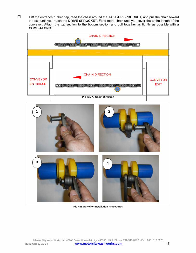
Lift the entrance rubber flap, feed the chain around the TAKE-UP SPROCKET, and pull the chain toward the exit until you reach the DRIVE SPROCKET. Feed more chain until you cover the entire length of the conveyor. Attach the top section to the bottom section and pull together as tightly as possible with a COME-ALONG.
CHAIN DIRECTION
CONVEYOR
ENTRANCECONVEYOR
EXIT
CHAIN DIRECTION
Pic #35-A: Chain Direction
Pic #41-A: Roller Installation Procedures
2
4
1
3
© Motor City Wash Works, Inc. 48285 Frank, Wixom Michigan 48393 U.S.A. Phone: 248.313.0272 ▪ Fax: 248. 313.0271 VERSION: 02-20-14 www.motorcitywashworks.com 18
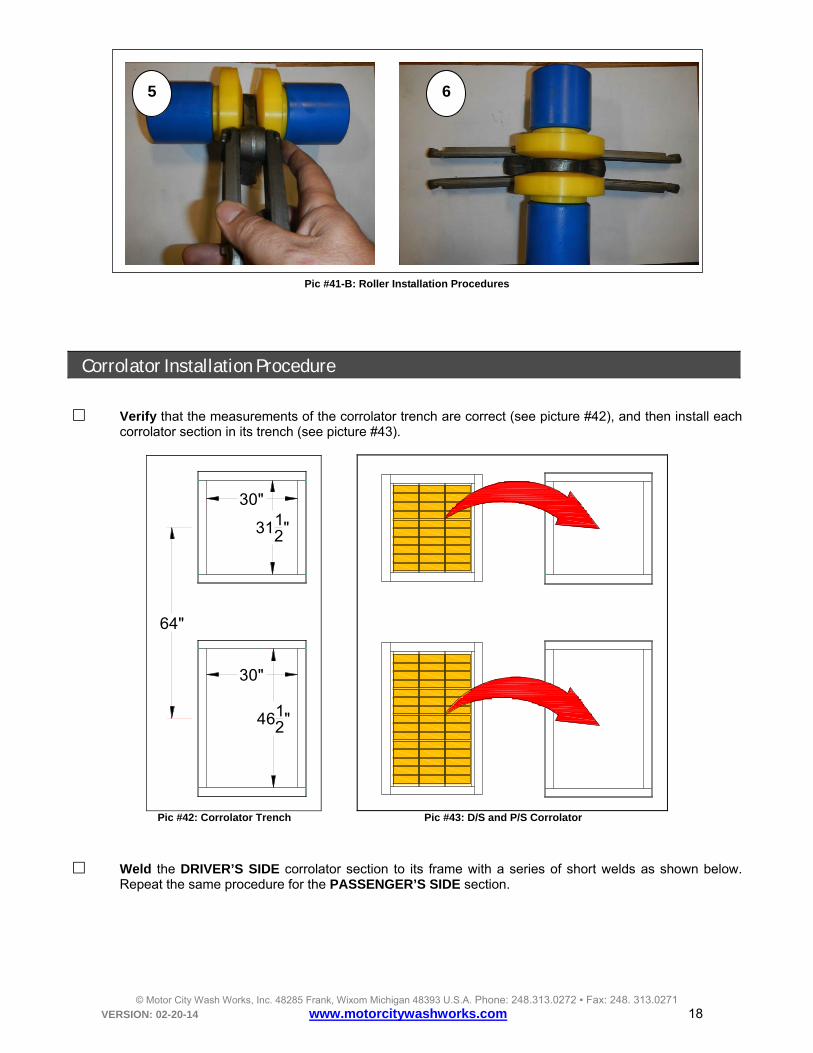
Pic #41-B: Roller Installation Procedures
Corrolator Installation Procedure
Verify that the measurements of the corrolator trench are correct (see picture #42), and then install each corrolator section in its trench (see picture #43).
30"
3112"
30"
4612"
64"
Pic #42: Corrolator Trench Pic #43: D/S and P/S Corrolator
Weld the DRIVER’S SIDE corrolator section to its frame with a series of short welds as shown below. Repeat the same procedure for the PASSENGER’S SIDE section.
6 5

© Motor City Wash Works, Inc. 48285 Frank, Wixom Michigan 48393 U.S.A. Phone: 248.313.0272 ▪ Fax: 248. 313.0271 VERSION: 02-20-14 www.motorcitywashworks.com 19
WELDHERE
Pic #44: Weld Corrolator Section
Locate the CORROLATOR GUIDE RAILS and bring them to the corrolator. There are two different models of corrolator guide rails: ANGLE Y GUIDE RAILS (see picture #45) or ROLLING Y GUIDE RAILS (see picture #46).
Pic #45: Corrolator Angle Guide Rails Pic #46: Corrolator Roller Guide Rails
Angle Guide Rails:
Position the guide rails above the DRIVER’S SIDE corrolator frame assembly (as shown on picture #47). You may have to cut the angle piece connecting the Y section to the conveyor guide rail to accommodate the distance to the conveyor.
Weld the guide rail weldment to the corrolator frame and then to the conveyor guide rails (see picture
#48).

© Motor City Wash Works, Inc. 48285 Frank, Wixom Michigan 48393 U.S.A. Phone: 248.313.0272 ▪ Fax: 248. 313.0271 VERSION: 02-20-14 www.motorcitywashworks.com 20
CUT TO FIT
Pic #47: Cut Transition Guide Rail Pic #48: Weld Guide Rails
Rolling Guide Rails:
Assemble the two DRIVER’S and PASSENGER’S SIDE Y-SECTIONS: The driver side rolling Y section consists of the ENTRANCE Y-SECTION AXLE WELDMENT LONG and a LONG MOUNT (see picture #49); the passenger side consists of an ENTRANCE Y-SECTION AXLE WELDMENT SHORT and a SHORT MOUNT (see picture #50).
Pic #49: Driver Side Entrance Y-Section Assy. Pic #50: Passenger Side Entrance Y-Section Assy. Position the two rolling guide rails above the DRIVER’S SIDE corrolator frame assembly (as previously
shown on picture #47). You may have to cut the transition angle guide rail piece connecting the Y section to the conveyor guide rail in order to accommodate the distance to the conveyor.
Weld tack the guide rail mounts to the corrolator frame and the transition weldment to the conveyor guide rails (see picture #51).
Remove the roller guide rails by taking apart the ENTRANCE Y-SECTION AXLE WELDMENT from the MOUNT, and then reassemble the axle weldment to the mount and solidly weld the guide rail mounts to the corrolator frame (see picture #53). Weld the transition weldment to the corrolator frame (see Picture #52) and to the conveyor guide rails.
WELD HERE
WELD HERE
ENT. WELDMENT
LONG
MOUNT LONG
ENT. WELDMENT
SHORT
MOUNT SHORT

© Motor City Wash Works, Inc. 48285 Frank, Wixom Michigan 48393 U.S.A. Phone: 248.313.0272 ▪ Fax: 248. 313.0271 VERSION: 02-20-14 www.motorcitywashworks.com 21
Pic #51: Tack Guide Rail Mount Pic #52: Weld Guide Rails
Pic #53: Axle Weldment Reassembled Before Final Weld Pic #54: Transition Angle Mount Weld
Pneumatic Installation: Locate the air panel (see picture #55) and mount it in a dry area, like the mechanical room. Pull FOUR
3/8” air lines, one BLUE, one YELLOW, ONE RED, ONE NATURAL from the conveyor entrance section to the air panel. Connect the BLUE line from the ROLLER UP EXTEND VALVE (see below) to the ROLLER UP CYLINDER (see picture #56).
Pic #55: CV Air Panel
TACK WELD HERE
WELD HERE
WELD HERE
WELD HERE
WELD HERE

© Motor City Wash Works, Inc. 48285 Frank, Wixom Michigan 48393 U.S.A. Phone: 248.313.0272 ▪ Fax: 248. 313.0271 VERSION: 02-20-14 www.motorcitywashworks.com 22
Pic #56: Roller Up Cylinder Pic #57: Air Take-Up Cylinder Connect the YELLOW line from the ROLLER UP EXTEND VALVE (see picture #55) to the ROLLER UP
CYLINDER (see picture #56). Connect the RED line from the TAKE-UP MANUAL VALVE (see picture #55) to the TAKE-UP CYLINDER red lines (see picture #56). Finally, Connect the NATURAL line from the TAKE-UP MANUAL VALVE (see picture #55) to the TAKE-UP CYLINDER clear lines (see picture #56).
Finally, connect the AIR PANEL AIR SUPPLY to a source capable of 2SCFM @ 100PSI (min) open the air supply and set the CHAIN TENSION REGULATOR TO 80 PSI. Set the ROLLER-UP CYLINDER REGULATOR TO 40 PSI.
WARNING! IT IS IMPERATIVE TO SUPPLY THE CONVEYOR AIR PANEL WITH CLEAN,
DRY, COMPRESSED AIR. ANY AMOUNT OF MOISTURE, VAPORIZED OIL, OR ANY OTHER IMPURITIES WITHIN THE MAIN AIR SUPPLY MAY
AFFECT THE PERFORMANCE OF THE EQUIPMENT AND LEAD TO PREMATURE WEAR OR MAJOR DAMAGE TO THE CONVEYOR ROLLER UP SYSTEM.
WARNING! THE MATERIAL REQUIRED FOR CONNECTING THE AIR SUPPLY TO THE AIR PANEL IS THE CUSTOMER’S RESPONSIBILITY! ALL WORK HAS TO COMPLY WITH LOCAL AND NATIONAL CODES!
ROLLER UP CYLINDER
CONNECT BLUE LINE HERE
CONNECT YLW LINE HERE
CONNECT RED LINE HERE
CONNECT NATURAL LINE HERE
© Motor City Wash Works, Inc. 48285 Frank, Wixom Michigan 48393 U.S.A. Phone: 248.313.0272 ▪ Fax: 248. 313.0271 VERSION: 02-20-14 www.motorcitywashworks.com 23
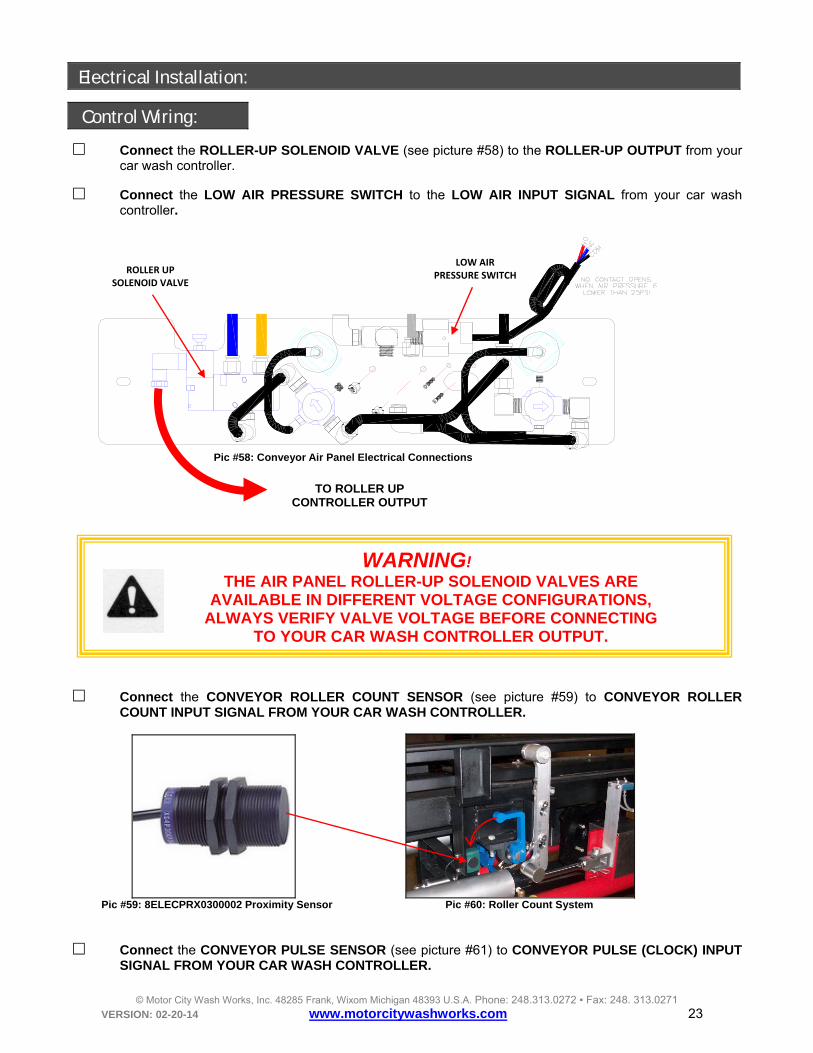
Electrical Installation:
Control Wiring:
Connect the ROLLER-UP SOLENOID VALVE (see picture #58) to the ROLLER-UP OUTPUT from your car wash controller.
Connect the LOW AIR PRESSURE SWITCH to the LOW AIR INPUT SIGNAL from your car wash controller.
Pic #58: Conveyor Air Panel Electrical Connections
WARNING! THE AIR PANEL ROLLER-UP SOLENOID VALVES ARE
AVAILABLE IN DIFFERENT VOLTAGE CONFIGURATIONS, ALWAYS VERIFY VALVE VOLTAGE BEFORE CONNECTING
TO YOUR CAR WASH CONTROLLER OUTPUT.
Connect the CONVEYOR ROLLER COUNT SENSOR (see picture #59) to CONVEYOR ROLLER COUNT INPUT SIGNAL FROM YOUR CAR WASH CONTROLLER.
Pic #59: 8ELECPRX0300002 Proximity Sensor Pic #60: Roller Count System
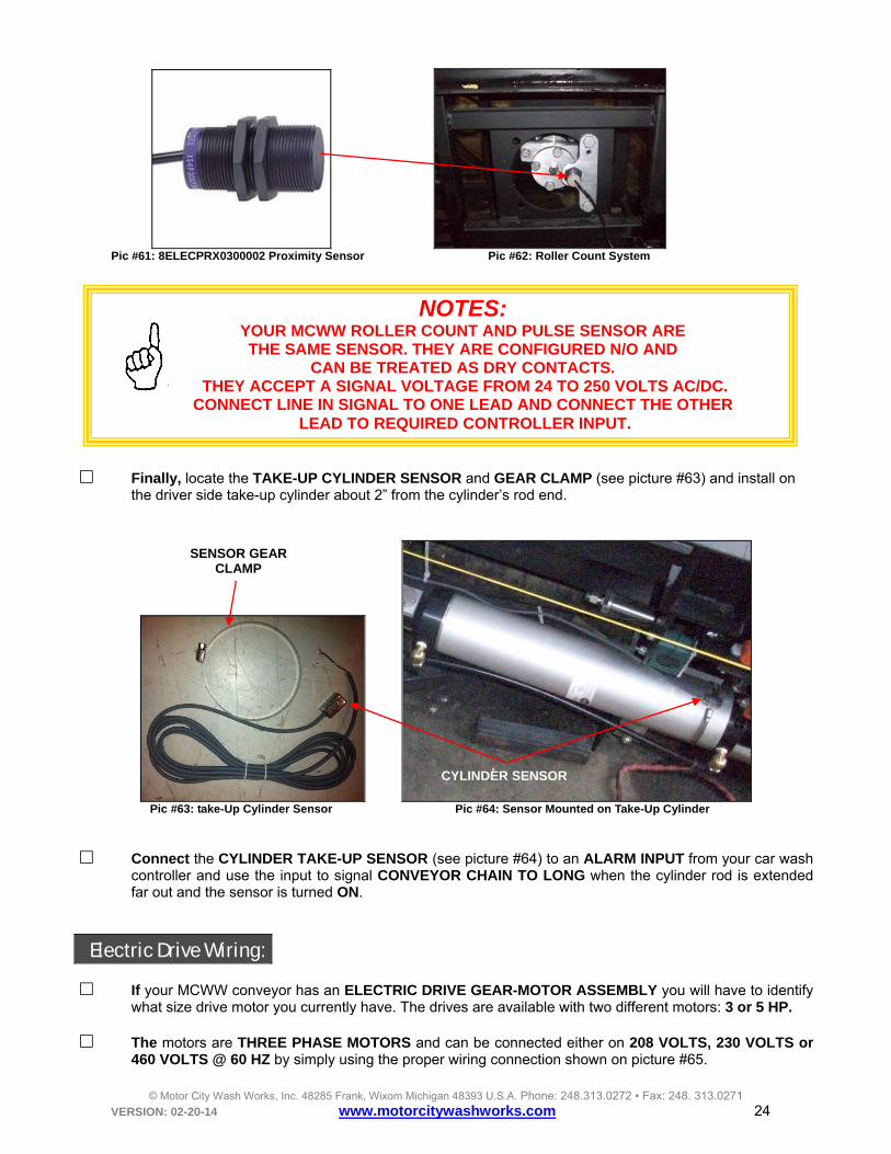
Connect the CONVEYOR PULSE SENSOR (see picture #61) to CONVEYOR PULSE (CLOCK) INPUT SIGNAL FROM YOUR CAR WASH CONTROLLER.
TO ROLLER UP CONTROLLER OUTPUT
LOW AIRPRESSURE SWITCH
ROLLER UP SOLENOID VALVE
© Motor City Wash Works, Inc. 48285 Frank, Wixom Michigan 48393 U.S.A. Phone: 248.313.0272 ▪ Fax: 248. 313.0271 VERSION: 02-20-14 www.motorcitywashworks.com 24
Pic #61: 8ELECPRX0300002 Proximity Sensor Pic #62: Roller Count System
Finally, locate the TAKE-UP CYLINDER SENSOR and GEAR CLAMP (see picture #63) and install on
the driver side take-up cylinder about 2” from the cylinder’s rod end.
Pic #63: take-Up Cylinder Sensor Pic #64: Sensor Mounted on Take-Up Cylinder
Connect the CYLINDER TAKE-UP SENSOR (see picture #64) to an ALARM INPUT from your car wash
controller and use the input to signal CONVEYOR CHAIN TO LONG when the cylinder rod is extended far out and the sensor is turned ON.
Electric Drive Wiring: If your MCWW conveyor has an ELECTRIC DRIVE GEAR-MOTOR ASSEMBLY you will have to identify
what size drive motor you currently have. The drives are available with two different motors: 3 or 5 HP.
The motors are THREE PHASE MOTORS and can be connected either on 208 VOLTS, 230 VOLTS or 460 VOLTS @ 60 HZ by simply using the proper wiring connection shown on picture #65.
NOTES: YOUR MCWW ROLLER COUNT AND PULSE SENSOR ARE THE SAME SENSOR. THEY ARE CONFIGURED N/O AND
CAN BE TREATED AS DRY CONTACTS. THEY ACCEPT A SIGNAL VOLTAGE FROM 24 TO 250 VOLTS AC/DC.
CONNECT LINE IN SIGNAL TO ONE LEAD AND CONNECT THE OTHER LEAD TO REQUIRED CONTROLLER INPUT.
SENSOR GEAR CLAMP
CYLINDER SENSOR

© Motor City Wash Works, Inc. 48285 Frank, Wixom Michigan 48393 U.S.A. Phone: 248.313.0272 ▪ Fax: 248. 313.0271 VERSION: 02-20-14 www.motorcitywashworks.com 25
Pic #65 Motor Connection
WARNING! THE MATERIALS REQUIRED FOR CONNECTING
THE CONVEYOR MOTOR ARE THE CUSTOMER’S RESPONSIBILITY!
ALL WORK HAS TO COMPLY WITH LOCAL AND NATIONAL CODES!
In order to vary the output speed, the drive motor can only be connected to a VARIABLE FREQUENCY
DRIVE (VFD). A Variable Frequency Drive (VFD) also called AC DRIVE, INVERTER, ADJUSTABLE FREQUENCY DRIVE and VARIABLE SPEED DRIVE is a type of controller that drives the electric motor by varying the frequency and voltage supplied to the motor. The FREQUENCY or HERTZ is directly related to the motor’s SPEED or RPM (REVOLUTION PER MINUTES): the higher the frequency, the faster the motor runs. The VFD is also used to RAMP UP the speed of the motor, permitting a SMOOTHER ACCELERATION after starting. It can also slow down or DECELERATE the motor and its load in a controlled time period. For your conveyor application, the VFD will be set to let the motor decelerate by itself or (FREE SPIN) until it stopped.
MCWW offers four different OVERDRIVE® VFD PANEL: 3 and 5HP at 208-230VAC and 460VAC three phase (see pictures below).
OVERDRIVEMotor and Equipment SolutionMCWW
A MP S: 20A
HP: 3.0
NEMA 1 ENCLOS URE
HZ: 60FLA : 11 .0
P H: 3
SNGL VFD-SNGL MOTOR V OLTA GE : 460
MCWW SUPERDUTY CONVEYOR
8DCA LVFDSNG0023
OVERDRIVEMotor and Equipment SolutionMCWW
A MP S: 30A
HP: 5 .0
NEMA 1 ENCLOS URE
HZ: 60FLA : 17.5
P H: 3
SNGL VFD-SNGL MOTOR V OLTA GE : 208
MCWW SUPERDUTY CONVEYOR
8DCA LVFDSNG0023
Pic #66: 208-230VAC-3HP Overdrive® Panel Pic #67: 208-230VAC-5HP Overdrive® Panel

© Motor City Wash Works, Inc. 48285 Frank, Wixom Michigan 48393 U.S.A. Phone: 248.313.0272 ▪ Fax: 248. 313.0271 VERSION: 02-20-14 www.motorcitywashworks.com 26
OVERDRIVEMotor and Equipment SolutionMCWW
A MP S: 15
HP: 5 .0
NEMA 1 ENCLOS URE
HZ: 60FLA : 7.6
P H: 3
SNGL VFD-SNGL MOTOR V OLTA GE : 460
MCWW SUPERDUTY CONVEYOR
8DCA LVFDSNG0023
OVERDRIVEMotor and Equipment SolutionMCWW
A MP S: 15
HP: 3.0
NEMA 1 ENCLOS URE
HZ: 60FLA : 4.8
P H: 3
SNGL VFD-SNGL MOTOR V OLTA GE : 460
MCWW SUPERDUTY CONVEYOR
8DCA LVFDSNG0023
Pic #68: 460VAC-3HP Overdrive® Panel Pic #69: 460VAC-5HP Overdrive® Panel
Connect the OVERDRIVE® VFD PANEL has shown on picture below: 1- Supply panel with proper voltage 208-230VAC or 460VAC 3PH. 2- Connect motor to VFD output: wire motor according to voltage used (see picture #63
for connection diagram). 3- Connect an alarm input (fault) from your car wash controller to R1-A and R1-C. The
VFD internal relay R1 is open unless the drive is FAULTED. 4- Finally, connect an output from your car wash controller to the RUN SIGNAL INPUT
RELAY A1-A2. The signal can be of any voltage between 24 to 250 VOLT AC or DC.
L1L2L3
T1 T2 T3
CB1
VFD1
TR1
A1 A2R1
C
R1
A
24-250V AC/DC
CAR WASH CONTROLLER
NEUTRAL
24V AC/DC
OUTPUTS MODULE
INPUTS MODULE
+ VDC or HOT
Pic #70: Overdrive® VFD Panel Connection Diagram
VFD (VARIABLE
FREQUENCY DRIVE)
CHECK VFD VOLTAGE
BEFORE TURNING POWER ON!
CONNECT R1-A AND
R1-C TO AN ALARM INPUT
CONNECT A1 AND A2
TO CONVEYOR
RUN SIGNAL
MCWW OVERDRIVE® VFD PANEL

© Motor City Wash Works, Inc. 48285 Frank, Wixom Michigan 48393 U.S.A. Phone: 248.313.0272 ▪ Fax: 248. 313.0271 VERSION: 02-20-14 www.motorcitywashworks.com 27
WARNING! IF THE DISTANCE BETWEEN THE INVERTER PANEL AND THE MOTOR IS GREATER THAN 100 FEET, SHIELDED CABLE AND
SHIELDED CONNECTORS MUST BE USED.
Hydraulic Drive Installation: If your MCWW conveyor has a HYDRAULIC DRIVEN MOTOR ASSEMBLY, you will need to supply and
install two hydraulic lines from your HYDRAULIC POWER UNIT to the HYDRAULIC GEAR-MOTOR (see picture #71).
PRESSURE
RETURN
4GPM @1000PSI FOR 60 CARS PER HOUR6GPM @1000PSI FOR 120 CARS PER HOUR
Pic #71: Conveyor Hydraulic Connections
Pic #72: Hydraulic Motor Rotation
PRESSURE LINE
RETURN LINE
HYDRAULIC UNIT

© Motor City Wash Works, Inc. 48285 Frank, Wixom Michigan 48393 U.S.A. Phone: 248.313.0272 ▪ Fax: 248. 313.0271 VERSION: 02-20-14 www.motorcitywashworks.com 28
WARNING! YOUR HYDRAULIC MOTOR ASSEMBLY RUNS WITH THE FOLLOWING FLUIDS:
- ALL SEALED AND OPEN SEAL (BEARING-LESS) GEAR-MOTOR ASSEMBLIES WILL RUN WITH PREMIUM GRADE HYDRAULIC OIL,150 (SUS) VISCOSITY @ 100°F MEETING ISO 40 REQUIREMENTS.
- ONLY SEALED GEAR-MOTOR ASSEMBLIES CAN RUN WITH WATER/GLYCOL BASED FLUID LIKE:
HOUGHTO SAFE 620: http://www.houghton.ca/products.asp?Cat=2&SubCat=13 AQUABLUE: http://www.tapcollc.com/aquablue2.html
UCON™ HYDROLUBE DG-732: http://www.dow.com/ucon/formulated/fluids/fire_res.htm
DO NOT RUN OPEN SEAL (BEARING-LESS) GEAR-MOTOR USING WATER BASED FLUID!
DOING SO WILL REDUCE THE LIFE OF THE GEAR-REDUCER AND WILL VOID YOUR WARRANTY!
The speed of the gear-motor depends on the hydraulic flow (in GPM) delivered to the motor and the size of the motor (in CUBIC INCH). Use the chart below to determine the size of the hydraulic unit with the desired speed of your conveyor.
CONVEYOR MOTOR GPM REQUIRED
CARS PER HOUR 14 CUBIC INCH 18 CUBIC INCH
(CV LESS THAN 130FT) 22 CUBIC INCH
(CV OVER 130 FT) 24 CUBIC INCH
(CV OVER 130 FT)
60 2.6 3.5 4.2 4.5 70 3 4 5 5.2
80 3.5 4.5 5.6 6
90 4 5 6.3 6.7
100 4.3 5.6 7 7.5
110 4.8 6.1 7.8 8.2
120 5.2 6.7 8.4 9 130 5.6 7.2 9.1 9.7 140 6 7.8 9.8 10.4 150 6.5 8.3 10.5 11.2 160 6.9 8.9 11.2 11.9 170 7.3 9.4 11.9 12.6 180 7.8 10 12.6 13.4 190 8.2 10.5 13.3 14 200 8.6 11 14 14.9 210 9 11.7 14.7 15.6 220 9.5 12.2 15.4 16.4

© Motor City Wash Works, Inc. 48285 Frank, Wixom Michigan 48393 U.S.A. Phone: 248.313.0272 ▪ Fax: 248. 313.0271 VERSION: 02-20-14 www.motorcitywashworks.com 29
Plastic Guide Rails Installation Procedure
Your MCWW conveyor comes with a plastic guide rail that has to be installed on BOTH SIDES. Locate the entrance plastic guide rail which came with your corrolator Y section (see picture #71) and snap it to the steel angle like shown on step 1 (picture #73 below). Locate the first hole, using the hole-locator tool supplied with your conveyor and drill a 11/32” diameter hole thru the guide rail (see step 2 Picture #74). Secure the guide rail plastic using the supplied button head screws and nylock nuts (see step 3 Picture #74).
Pic #73: Entrance Plastic Guide Rail
Pic #74: Plastic Guide Rail Installation
Install next plastic guide using the same procedure until you reach the exit. You may also drill additional hole close to the end of a guide rails section as well as at the beginning of the next section when required.
Pic #75: Plastic Guide Rail Installed
1 2 3
SNAP AROUND THE ANGLE
HOLE LOCATOR
TOOL
SECURE WITH 5/16-18
BUTTON HEAD FASTENERS
DRILL 11/32” HOLE

© Motor City Wash Works, Inc. 48285 Frank, Wixom Michigan 48393 U.S.A. Phone: 248.313.0272 ▪ Fax: 248. 313.0271 VERSION: 02-20-14 www.motorcitywashworks.com 30
Start-Up Procedure:
At START-UP, set the CHAIN TENSION (AIR TAKE-UP) air pressure at 80PSI and the DOLLIE-UP (ROLLER-UP) at 40PSI (see picture #76 below).
AIR ADJUSTMENT
ON OFF
DOLLIE-UP AIR PRESSURE
MANUAL OVERRIDE
MCWW CONVEYORSUPER DUTY
CHAIN TENSION
CHAIN TENSION
Pic #756 CV Air Panel
Verify that the chain is sufficiently tight. If not, you may have to remove some chain link using a come-along.
Verify the entire control input signals: the CONVEYOR PULSE SENSOR, ROLLER COUNT SENSOR as
well as proper operation of the ROLLER-UP RAMP and AIR PANEL.
Start the conveyor at the slowest speed and verify the direction of the chain. Reverse if necessary.
NOTE: TO REVERSE THE ROTATION OF A HYDRAULIC MOTOR,
REVERSE THE HYDRAULIC HOSES AT THE MOTOR (SEE PICTURE #72).
TO REVERSE THE ROTATION OF AN ELECTRIC MOTOR, REVERSE TWO LEAD WIRES AT THE MOTOR CONNECTION BOX
OR AT THE INVERTER OUTPUT WIRES (SEE PICTURE #70).
While the conveyor is still running, verify that the conveyor stops or cannot start if the air is low or missing
by shifting the CHAIN TENSION LEVER and hear the air hissing from the valve, the conveyor stopping and the chain becoming loose.
80PSI
40PSI
© Motor City Wash Works, Inc. 48285 Frank, Wixom Michigan 48393 U.S.A. Phone: 248.313.0272 ▪ Fax: 248. 313.0271 VERSION: 02-20-14 www.motorcitywashworks.com 31
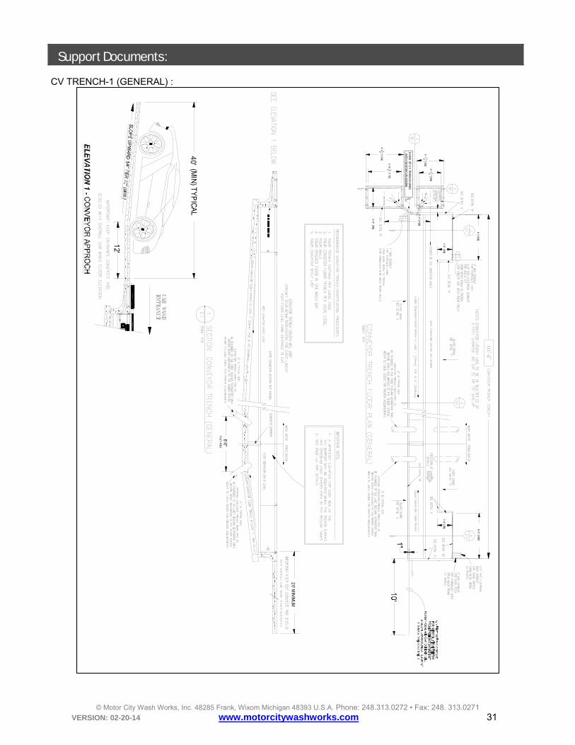
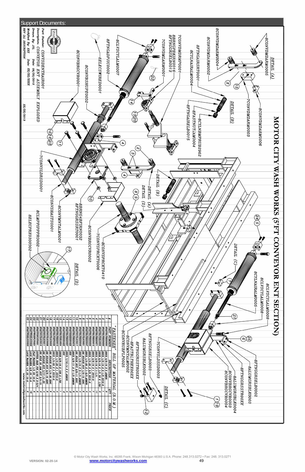
Support Documents: CV TRENCH-1 (GENERAL) :
2'-712 " [800]
3'-112 " [952]
3'-1012 " [1181]
4'-4 12 " [1334]
2'-6" [762]
5'-4" [1626]
6' [1829]
1'-8" [508]
6'-0" [1827]
1'-8" [508]
20' M
INIM
UM
ED
GE
OF
CV
TRE
NC
H LIN
ED
WIT
H C
EN
TE
R O
N D
OO
RS
1"
12'
40'(M
IN) T
YP
ICA
L
8'-0"
FLA
T AREA

© Motor City Wash Works, Inc. 48285 Frank, Wixom Michigan 48393 U.S.A. Phone: 248.313.0272 ▪ Fax: 248. 313.0271 VERSION: 02-20-14 www.motorcitywashworks.com 32
CV TRENCH DETAILS:
1" (2
54m
m)
TYP
22
" (55
88 mm
)M
INIM
UM
20" [508mm
]60" [1524m
m]
1" (2
54m
m)
TYP
22
" (55
88 mm
)M
INIM
UM
40" [1016mm
]60" [1524m
m]
1" (2
54m
m)
TYP
22
" (55
88 mm
)M
INIM
UM
40" [1016mm
]
2'-6"2'-6"
3'-10 12 "2'-7 12 "
© Motor City Wash Works, Inc. 48285 Frank, Wixom Michigan 48393 U.S.A. Phone: 248.313.0272 ▪ Fax: 248. 313.0271 VERSION: 02-20-14 www.motorcitywashworks.com 33
HYDRAULIC UNITS :

© Motor City Wash Works, Inc. 48285 Frank, Wixom Michigan 48393 U.S.A. Phone: 248.313.0272 ▪ Fax: 248. 313.0271 VERSION: 02-20-14 www.motorcitywashworks.com 34
A-FRAME DWG:
CASTERS HOLE PATERN
(8) 1/2"-13 X 6" + NYLOCK NUTS
(2) 1/2"-13 X 1-1/4"
© Motor City Wash Works, Inc. 48285 Frank, Wixom Michigan 48393 U.S.A. Phone: 248.313.0272 ▪ Fax: 248. 313.0271 VERSION: 02-20-14 www.motorcitywashworks.com 35

© Motor City Wash Works, Inc. 48285 Frank, Wixom Michigan 48393 U.S.A. Phone: 248.313.0272 ▪ Fax: 248. 313.0271 VERSION: 02-20-14 www.motorcitywashworks.com 36
3.6
25
0.6
250
.313
0.0
00
Ø2.000
1.003ID+.000-.003
Ø6.000
1.5
062
.000
2.2
502
.744 Ø5.013
Ø4.5130.0000.4940.744
R2.000Ø1.6253 HOLES 3/8"X16 THREAD THRU PART
R0.250
0.0
00
1.5
00
12.
327
13.
702
13.
390
15.
384
10.
452
11.
577
1.188
2.813
2.000
4.000
Ø0.531
Ø1.016
0.750
0.000
R 1" TYPICAL

© Motor City Wash Works, Inc. 48285 Frank, Wixom Michigan 48393 U.S.A. Phone: 248.313.0272 ▪ Fax: 248. 313.0271 VERSION: 02-20-14 www.motorcitywashworks.com 37
0.00
0
4.75
0
1.000
THREADED 1/2"-13, 3/4" DEEP
0.750
0.750 0.125
72"
© Motor City Wash Works, Inc. 48285 Frank, Wixom Michigan 48393 U.S.A. Phone: 248.313.0272 ▪ Fax: 248. 313.0271 VERSION: 02-20-14 www.motorcitywashworks.com 38
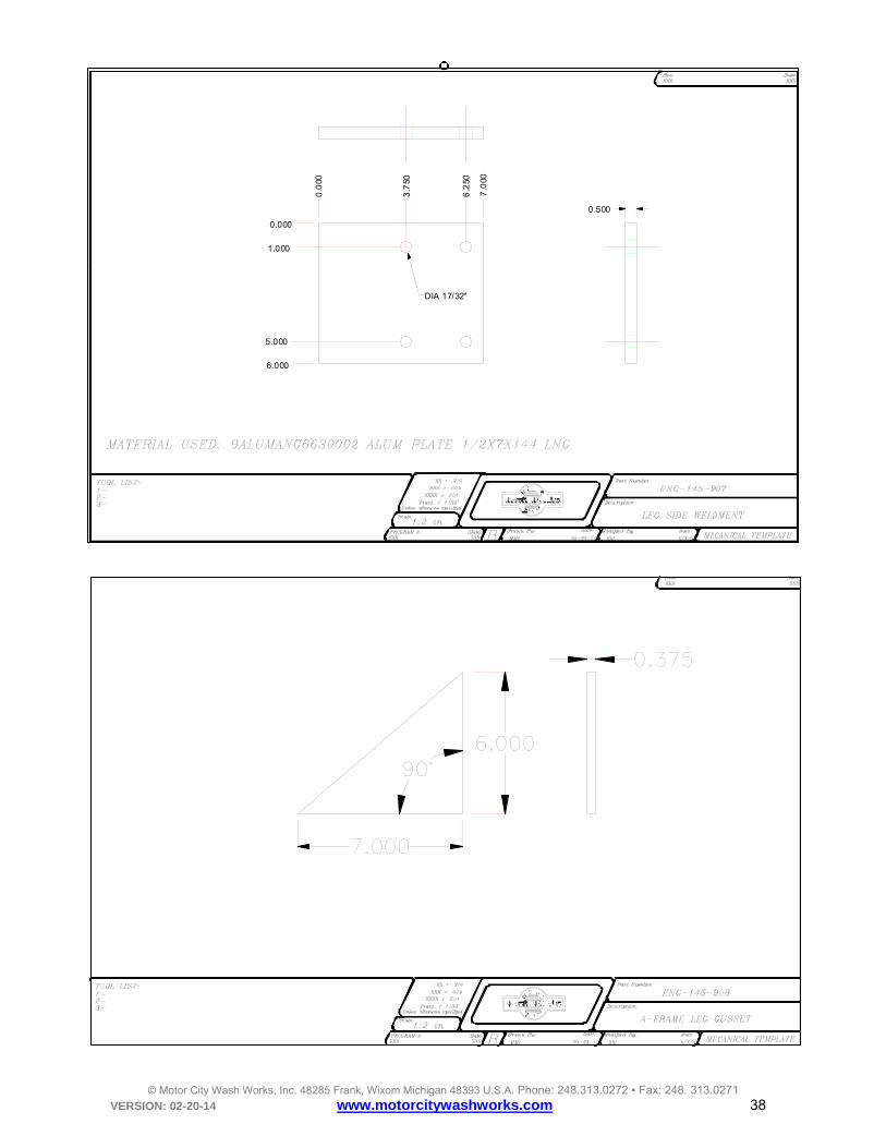
0.0
00
3.7
50
6.2
50
7.0
00
0.000
1.000
5.000
6.000
0.500
DIA 17/32"

© Motor City Wash Works, Inc. 48285 Frank, Wixom Michigan 48393 U.S.A. Phone: 248.313.0272 ▪ Fax: 248. 313.0271 VERSION: 02-20-14 www.motorcitywashworks.com 39
© Motor City Wash Works, Inc. 48285 Frank, Wixom Michigan 48393 U.S.A. Phone: 248.313.0272 ▪ Fax: 248. 313.0271 VERSION: 02-20-14 www.motorcitywashworks.com 40
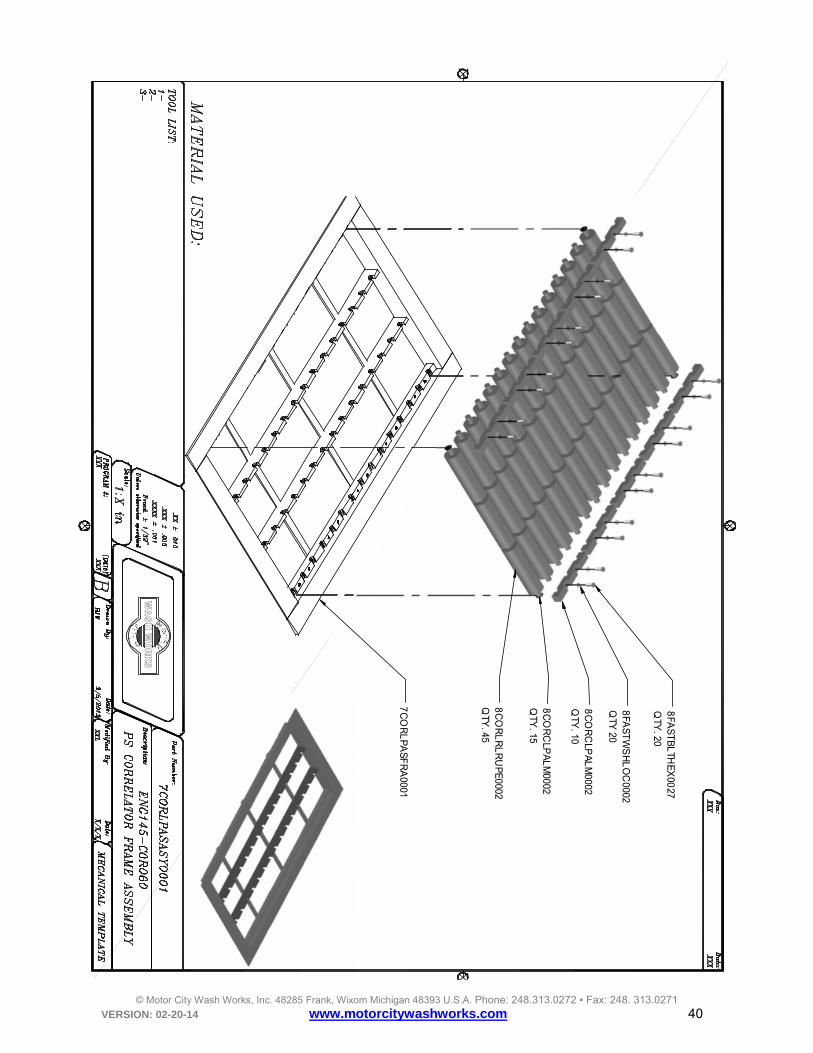
WA
SH
WO
RK
S
8FA
ST
BL
THE
X00
27Q
TY. 20
8FA
ST
WS
HL
OC
0002Q
TY 20
8C
OR
CLP
AL
M0002
QTY
. 10
8C
OR
CLP
AL
M0002
QTY
. 15
8C
OR
LR
LR
UP
E0002
QTY
. 45
7C
OR
LP
AS
FR
A0001

© Motor City Wash Works, Inc. 48285 Frank, Wixom Michigan 48393 U.S.A. Phone: 248.313.0272 ▪ Fax: 248. 313.0271 VERSION: 02-20-14 www.motorcitywashworks.com 41
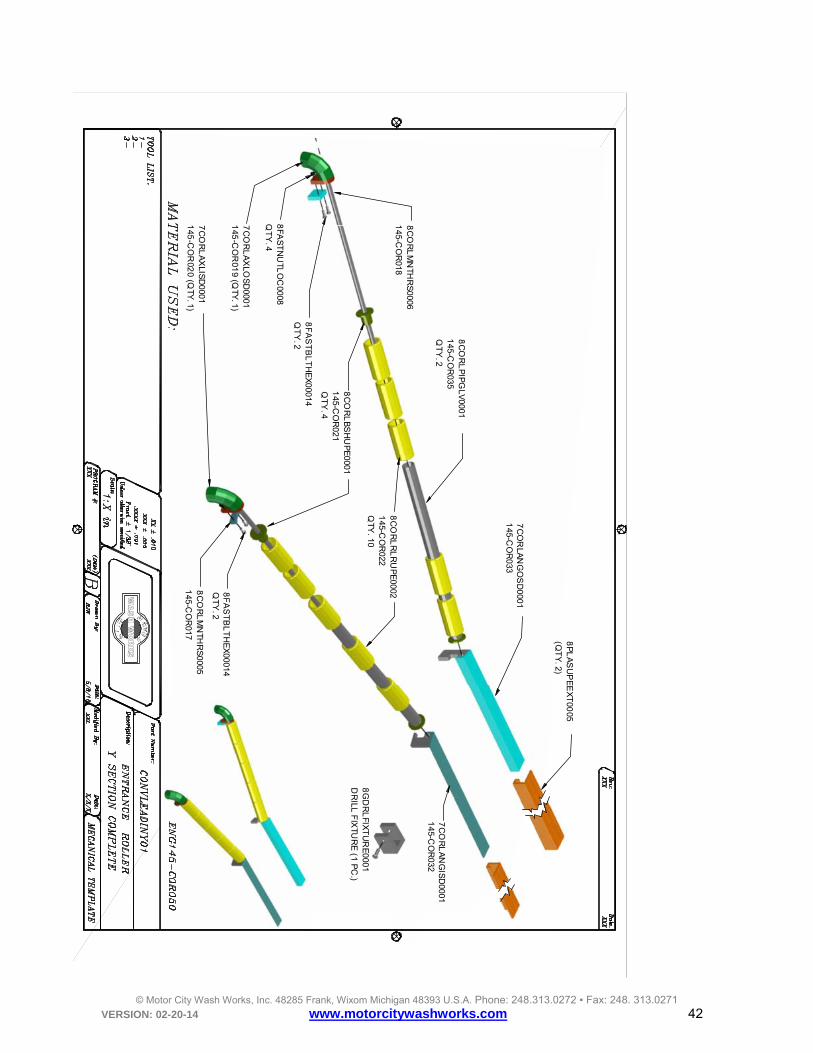
8C
OR
CL
PA
LM0002
(QT
Y. 4)
8F
AS
TB
LT
HE
X0027
(QT
Y. 12)
8F
AS
TW
SH
LOC
0002(Q
TY
. 12)
EN
G1
45
-CO
R002
(QT
Y. 2)
8C
OR
LA
XL
ST
S0001
(QT
Y. 2)
8C
OR
LR
LR
UP
E00
01(Q
TY
. 10)
7C
OR
LD
RV
FR
A00
01
© Motor City Wash Works, Inc. 48285 Frank, Wixom Michigan 48393 U.S.A. Phone: 248.313.0272 ▪ Fax: 248. 313.0271 VERSION: 02-20-14 www.motorcitywashworks.com 42
WA
SH
WO
RK
S
7C
OR
LAN
GO
SD
00011
45-CO
R033
8C
OR
LR
LR
UP
E0002
145-C
OR
022Q
TY. 10
8C
OR
LM
NTH
RS
00051
45-CO
R017
8F
AS
TB
LT
HE
X00014
QT
Y. 2
8FA
ST
NU
TLO
C0008
QT
Y. 4
7C
OR
LA
NG
ISD
00011
45-CO
R032
8C
OR
LM
NTH
RS
00061
45-CO
R018
8F
AS
TB
LT
HE
X00014
QT
Y. 2
8C
OR
LP
IPG
LV0001
145-C
OR
035Q
TY
. 2
8C
OR
LB
SH
UP
E0001
145-C
OR
021Q
TY
. 4
7C
OR
LA
XLIS
D0001
145
-CO
R02
0 (QTY
. 1)
8G
DR
LFIX
TU
RE
0001D
RILL
FIX
TUR
E (1 P
C.)
7C
OR
LA
XLO
SD
00011
45-C
OR
019 (Q
TY. 1)
8P
LA
SU
PE
EX
T00
05(Q
TY
. 2)
© Motor City Wash Works, Inc. 48285 Frank, Wixom Michigan 48393 U.S.A. Phone: 248.313.0272 ▪ Fax: 248. 313.0271 VERSION: 02-20-14 www.motorcitywashworks.com 43
XX
XX
X XX
XX
XX
XX
XX
XX
XX
XX
XX
X1
-XX
X2
-XX
X3
-XX
X4
-XX
X5
-XX
X6
-XX
X7
-XX
X8
-XX
X
TO
OL
LIST
Sc
ale:
Part N
um
ber:
Des
cription:
.XX
XX
± .001
.XX
± .010
Fra
ct. ± 1/32"
Unles
s otherw
ise specified
.XX
X ±
.005
NO
TE
S:
R
T0
M
WA
SH
WO
RK
SC
IT
Y
MIC
HIG
AN
0
MA
TE
RIA
L US
ED
: DE
SC
RIP
TIO
N H
ER
E : R
AW
MA
TE
RIA
L N
UM
BE
R H
ER
EE
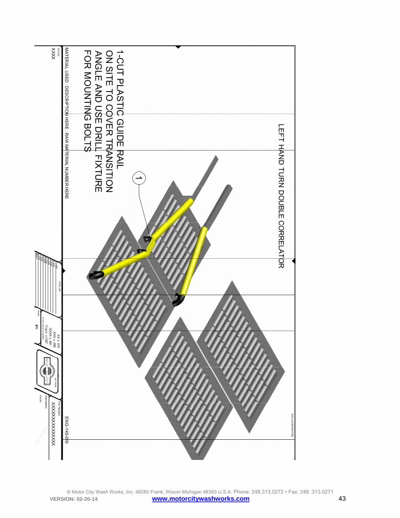
NG
-14
5-019
RE
V (A
) DE
SC
RIP
TIO
N
1
1-C
UT
PLA
ST
IC G
UID
E R
AIL
ON
SIT
E T
O C
OV
ER
TR
AN
SIT
ION
AN
GLE
AN
D U
SE
DR
ILL F
IXT
UR
EF
OR
MO
UN
TIN
G B
OLT
S
LE
FT
HA
ND
TU
RN
DO
UB
LE C
OR
RE
LAT
OR

© Motor City Wash Works, Inc. 48285 Frank, Wixom Michigan 48393 U.S.A. Phone: 248.313.0272 ▪ Fax: 248. 313.0271 VERSION: 02-20-14 www.motorcitywashworks.com 44
XX
XX
X XX
XX
XX
XX
XX
XX
XX
X
NTS
XX
XX
X/X
X/X
XX
XX
XX
XX
X/X
X/X
XX
X
XX
XX
1-X
XX
2-X
XX
3-X
XX
4-X
XX
5-X
XX
6-X
XX
7-X
XX
8-X
XX
9-X
XX
JTL
11/05
/2013
TO
OL LIS
T
Sc
ale:
Part N
um
ber:
Dra
wn
By:
B
Des
cription:
Mo
difie
d B
y:D
ate:
Da
te:
.XX
XX
± .001
.XX
± .010
Fra
ct. ± 1/32"
Unles
s otherw
ise specified
.XX
X ± .005
Ma
ste
rCA
M #
(Da
te)
NO
TE
S:
R
T0
M
WA
SH
WO
RK
SC
IT
Y
MIC
HIG
AN
0
MA
TE
RIA
L U
SE
D : D
ES
CR
IPT
ION
HE
RE
: RA
W M
ATE
RIA
L NU
MB
ER
HE
RE
EN
G-145
-020
RE
V (A
) DE
SC
RIP
TION
1
2
3
41
-7C
OR
LA
XLIS
D00
01 IN
SID
E R
OLL
ER
MO
UN
T S
HO
RT
FA
CTO
RY
AS
SE
MB
LY2
-7C
OR
LA
XLD
BL
0001
DO
UB
LE
CO
RR
EL
AT
OR
RO
LLE
R M
OU
NT TA
LL O
N S
ITE
AS
SE
MB
LED
3-7
CO
RL
AN
GO
SD
00
06
OU
TS
IDE
AN
GL
E T
RA
NS
ITION
MN
T TALL FA
CTO
RY
AS
SE
MB
LYN
OT
E: #
3 IS
CU
T T
O LE
NG
TH O
N S
ITE4
-7C
OR
LA
XLO
SD
0001
OU
TS
IDE
RO
LLE
R M
OU
NT TA
LL F
AC
TOR
Y A
SS
EM
BLY
LE
FT
HA
ND
TU
RN
DO
UB
LE C
OR
RE
LAT
OR

© Motor City Wash Works, Inc. 48285 Frank, Wixom Michigan 48393 U.S.A. Phone: 248.313.0272 ▪ Fax: 248. 313.0271 VERSION: 02-20-14 www.motorcitywashworks.com 45
XX
XX
X XX
XX
XX
XX
XX
XX
XX
X
NTS
XX
XX
X/X
X/X
XX
XX
XX
XX
X/X
X/X
XX
X
XX
XX
1-X
XX
2-X
XX
3-X
XX
4-X
XX
5-X
XX
6-X
XX
7-X
XX
8-X
XX
9-X
XX
JTL
11/05
/2013
TO
OL LIS
T
Sc
ale:
Part N
um
ber:
Dra
wn
By:
B
Des
cription:
Mo
difie
d B
y:D
ate:
Da
te:
.XX
XX
± .001
.XX
± .010
Fra
ct. ± 1/32"
Unles
s otherw
ise specified
.XX
X ± .005
Ma
ste
rCA
M #
(Da
te)
NO
TE
S:
R
T0
M
WA
SH
WO
RK
SC
IT
Y
MIC
HIG
AN
0
MA
TE
RIA
L U
SE
D : D
ES
CR
IPT
ION
HE
RE
: RA
W M
ATE
RIA
L NU
MB
ER
HE
RE
EN
G-145
-022
RE
V (A
) DE
SC
RIP
TION
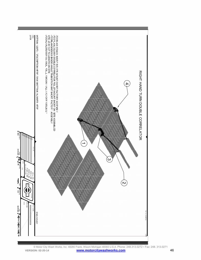
1
1-C
UT
PLA
ST
IC G
UID
E R
AIL
ON
SIT
E T
O C
OV
ER
TR
AN
SIT
ION
AN
GL
E A
ND
US
E D
RILL
FIX
TU
RE
FO
R M
OU
NT
ING
BO
LTS
RIG
HT
HA
ND
TU
RN
DO
UB
LE C
OR
RE
LAT
OR
© Motor City Wash Works, Inc. 48285 Frank, Wixom Michigan 48393 U.S.A. Phone: 248.313.0272 ▪ Fax: 248. 313.0271 VERSION: 02-20-14 www.motorcitywashworks.com 46
XX
XXX X
XX
XX
XX
XX
XX
XX
XX
NT
S
1-X
XX
2-X
XX
3-X
XX4
-XXX
5-X
XX6
-XXX
7-X
XX8
-XXX
9-X
XX
TO
OL LIST
Sca
le:
Pa
rt Num
ber:
Dra
wn
By:
De
sc
ription:
Mod
ified B
y:D
ate:D
ate:
.XX
XX
± .001
.XX
± .0
10
Fra
ct. ±
1/32"
Unle
ss otherw
ise sp
ecified
.XX
X ±
.005
Mas
terC
AM
#(D
ate)
R
T0
M
WA
SH
WO
RK
SC
IT
Y
MIC
HIG
AN
0
EN
G-14
5-021
RE
V (A
) DE
SCRIPTION
1
2
3
4
RIG
HT
HA
ND
TU
RN
DO
UB
LE
CO
RR
EL
AT
OR

© Motor City Wash Works, Inc. 48285 Frank, Wixom Michigan 48393 U.S.A. Phone: 248.313.0272 ▪ Fax: 248. 313.0271 VERSION: 02-20-14 www.motorcitywashworks.com 47
XX
XXX C
ON
VS
DLE
AD
INY
03
NT
S
XX
XX
X/X
X/XXXX
XX
XXX
X/X
X/XXXX
XX
XX
1-X
XX2
-XXX
3-X
XX4
-XXX
5-X
XX6
-XXX
7-X
XX8
-XXX
9-X
XX
DJC
02/19/14
TO
OL LIST
Sca
le:
Pa
rt Num
ber:
Dra
wn
By:
B
De
sc
ription:
Mod
ified B
y:D
ate:D
ate:
.XX
XX
± .001
.XX
± .010
Fra
ct. ± 1/32"U
nless oth
erwise
specified
.XX
X ± .005
Mas
terC
AM
#(D
ate)
NO
TE
S:
R
T0
M
WA
SH
WO
RK
SC
IT
Y
MIC
HIG
AN
0
MC
WW
EN
GIN
EE
RIN
G T
EA
M
MA
TER
IAL U
SE
D : D
ES
CR
IPTIO
N H
ER
E : R
AW
MA
TER
IAL N
UM
BE
R H
ER
EE
NG
NU
MB
ER
HE
RE
RE
V (A
) DE
SCRIPTION
XX/X
X/2014
8C
OR
LRLR
UP
E0002 Q
TY 15
8C
OR
LBS
HU
PE
0001 Q
TY 6
8C
OR
LPIP
GLV
0001 Q
TY 3
7C
OR
LAN
GIS
D0001
7C
OR
LA
NG
OS
D00
01
8C
OR
LM
NTH
RS
00
06
7C
OR
LAN
GO
SD
0001
7C
OR
LAX
LIS
D0001
8FA
STB
LTH
EX
0014 Q
TY 10
8C
OR
LM
NTH
RS
0005 Q
TY 3
7C
OR
LA
NG
OS
D0
00
6
8C
OR
LM
NTH
RS
0009
7C
OR
LAX
LDB
L00018C
OR
LM
NTH
RS
0009
8FA
STN
UTLO
C0008 Q
TY 10
7C
OR
LAN
GIS
D0006
8P
LAS
UP
EE
XT
0005 QTY
2

© Motor City Wash Works, Inc. 48285 Frank, Wixom Michigan 48393 U.S.A. Phone: 248.313.0272 ▪ Fax: 248. 313.0271 VERSION: 02-20-14 www.motorcitywashworks.com 48
Warranty and Return Procedure: Motor City Wash Works warrants this product to be free of defect in material and/or workmanship for a period of one year from the date of purchase. During the warranty period MCWW will at its discretion, at no charge to the customer, repair or replace this product if found defective, with a new or refurbished unit, not to include costs of removal or installation. Any product returned to MCWW for warranty has to have a Return Material Authorization Number. All shipping costs to MCWW are assumed by the customer. This is only a summary of MCWW’s Limited Warranty. Please, communicate with MCWW for our complete warranty. Prior to returning any product to MCWW, the customer must call in for a Return Material Authorization Number and a copy of our Return Material Authorization Form must be completed. The RMA number must be written clearly on the outside of the shipping package and a copy of the form must be included in the package.
© Motor City Wash Works, Inc. 48285 Frank, Wixom Michigan 48393 U.S.A. Phone: 248.313.0272 ▪ Fax: 248. 313.0271 VERSION: 02-20-14 www.motorcitywashworks.com 49
Support Documents:

© Motor City Wash Works, Inc. 48285 Frank, Wixom Michigan 48393 U.S.A. Phone: 248.313.0272 ▪ Fax: 248. 313.0271 VERSION: 02-20-14 www.motorcitywashworks.com 50

© Motor City Wash Works, Inc. 48285 Frank, Wixom Michigan 48393 U.S.A. Phone: 248.313.0272 ▪ Fax: 248. 313.0271 VERSION: 02-20-14 www.motorcitywashworks.com 51