super-hydrophobic/icephobic coatings based on silica
TRANSCRIPT

Liu, Junpeng and Janjua, Zaid A. and Roe, Martin and Xu, Fang and Turnbull, Barbara and Choi, Kwing-So and Hou, Xianghui (2016) Super-hydrophobic/icephobic coatings based on silica nanoparticles modified by self-assembled monolayers. Nanomaterials, 6 (12). 232/1-232/10. ISSN 2079-4991
Access from the University of Nottingham repository: http://eprints.nottingham.ac.uk/39137/1/nanomaterials-06-00232.pdf
Copyright and reuse:
The Nottingham ePrints service makes this work by researchers of the University of Nottingham available open access under the following conditions.
This article is made available under the Creative Commons Attribution licence and may be reused according to the conditions of the licence. For more details see: http://creativecommons.org/licenses/by/2.5/
A note on versions:
The version presented here may differ from the published version or from the version of record. If you wish to cite this item you are advised to consult the publisher’s version. Please see the repository url above for details on accessing the published version and note that access may require a subscription.
For more information, please contact [email protected]

nanomaterials
Article
Super-Hydrophobic/Icephobic CoatingsBased on Silica Nanoparticles Modifiedby Self-Assembled Monolayers
Junpeng Liu, Zaid A. Janjua, Martin Roe, Fang Xu, Barbara Turnbull, Kwing-So Choiand Xianghui Hou *
Faculty of Engineering, University of Nottingham, University Park, Nottingham NG7 2RD, UK;[email protected] (J.L.); [email protected] (Z.A.J.);[email protected] (M.R.); [email protected] (F.X.);[email protected] (B.T.); [email protected] (K.-S.C.)* Correspondence: [email protected]; Tel: +44-115-95-13920
Academic Editor: Thomas NannReceived: 1 October 2016; Accepted: 28 November 2016; Published: 2 December 2016
Abstract: A super-hydrophobic surface has been obtained from nanocomposite materials based onsilica nanoparticles and self-assembled monolayers of 1H,1H,2H,2H-perfluorooctyltriethoxysilane(POTS) using spin coating and chemical vapor deposition methods. Scanning electron microscopeimages reveal the porous structure of the silica nanoparticles, which can trap small-scale air pockets.An average water contact angle of 163◦ and bouncing off of incoming water droplets suggest that asuper-hydrophobic surface has been obtained based on the silica nanoparticles and POTS coating.The monitored water droplet icing test results show that icing is significantly delayed by silica-basednano-coatings compared with bare substrates and commercial icephobic products. Ice adhesion testresults show that the ice adhesion strength is reduced remarkably by silica-based nano-coatings.The bouncing phenomenon of water droplets, the icing delay performance and the lower ice adhesionstrength suggest that the super-hydrophobic coatings based on a combination of silica and POTS alsoshow icephobicity. An erosion test rig based on pressurized pneumatic water impinging impact wasused to evaluate the durability of the super-hydrophobic/icephobic coatings. The results show thatdurable coatings have been obtained, although improvement will be needed in future work aimingfor applications in aerospace.
Keywords: super-hydrophobic; icephobic; silica nanoparticles; fluorosilane; self-assembledmonolayers; durability
1. Introduction
Ice formation and accretion may hinder the economic and environmentally friendly operationof aircraft [1] and pose a serious hazard that may cause accidents. For aircraft, it is necessary tohave a de-icing and anti-icing system on the ground and during flight. However, current de-icingand anti-icing systems release chemicals into the environment, build up weight, increase fuelconsumption and add complexity to the aircraft systems [2]. Aiming for an environmentally friendlyand cost-effective way to solve the issue of ice formation and accretion, a durable icephobic coating onthe surface of aircraft is potentially an ideal solution.
A surface that exhibits a water contact angle of 150◦ or greater with very little flow resistanceis considered to be super-hydrophobic [3]. Super-hydrophobic surfaces are effective in allowingthe incoming water droplets to bounce off, delaying ice formation and reducing the ice adhesionstrength [4]. In order to fabricate super-hydrophobic surfaces, both the surface chemical compositionand morphology need to be tuned to achieve a low surface energy and desirable surface roughness [5].
Nanomaterials 2016, 6, 232; doi:10.3390/nano6120232 www.mdpi.com/journal/nanomaterials
Nanomaterials 2016, 6, 232 2 of 10
Various methods have been developed to prepare a rough surface from a low-surface-energymaterial or to modify a rough surface with a low-surface-energy material, such as electrochemistry,mechanical machining, chemical etching, spin coating and chemical vapor deposition [6–12].Among them, a combination of spin coating of a rough material and chemical vapor depositionof a low-surface-energy material is straightforward and inexpensive.
Coatings incorporating silica nanoparticles have been attracting significant interest due to highthermal and mechanical stability and high surface roughness [13]. Among low-surface-energymaterials, fluoroalkyl silanes are promising for practical applications because of their high mechanicaland chemical stability resulting from strong immobilization through siloxane bonding [14]. In previousresearch, hydrophobic coatings based on silica were widely reported. However, the icephobicity, icingbehavior and durability of coatings based on silica nanoparticles were less investigated. In addition,the durability of hydrophobic/icephobic coatings is very important for practical applications, especiallyin aircraft applications, and has remained challenging. Xu et al. [15] reported an erosion test methodbased on the impingement of water droplets released from a higher stage using gravity. In thisexperiment, an erosion test rig with the impact of impinging by high-velocity pneumatic water was setup and used to evaluate the durability.
In the current work, silica nanoparticles were deposited by the spin-coating method to form ananostructured rough surface to trap small-scale air pockets. Self-assembled monolayers (SAMs) offluoroalkyl silane, 1H,1H,2H,2H-perfluorooctyltriethoxysilane (POTS), were grafted onto the silicananoparticle surface by the chemical vapor deposition method to obtain a low surface energy.The hydrophobicity, icephobicity and durability of the coatings were investigated.
2. Experimental Section
2.1. Fabrication of Silica-Based Nano-Coatings with Self-Assembled Monolayers
Silica nanoparticles, polystyrene and POTS (98%) were purchased from Sigma-Aldrich Company(Dorset, UK). Chloroform was purchased from Fisher Scientific Company (Loughborough, UK).All chemicals were used as received. 0.5 g silica nanoparticles and 0.019 g polystyrene were dissolvedinto 30 mL chloroform by continuous stirring for about 1 h. The mixture was deposited onto substratesat a speed of 1500 rad/min for 1 min using a spin coater (KW-4A, Chemat Group, Northridge, CA, USA).For ice adhesion test, the Al substrates with roughness average (Ra) of 2.64 nm in area of 5 µm × 5 µmare alloy (2024-T4). For all other tests, the substrates are glasses with Ra of 1.66 nm in area of 5 µm × 5 µm.
Then the samples were transferred into a furnace for heat treatment at 550 ◦C for 2 h to removethe organic components and fuse the silica nanoparticles together. Then the silica based coatings withthickness of about 30 µm were formed. To reduce the surface energy and obtain super-hydrophobicsurfaces, the samples were grafted by self-assembled monolayers of POTS using chemical vapordeposition method in a sealed vessel with 0.3 mL POTS at 180 ◦C for 3 h. Coatings based on commercialsuper-hydrophobic and icephobic silicone were also fabricated for comparison.
2.2. Characterization of Morphology, Composition and Hydrophobicity
The surface morphology was investigated by a scanning electron microscope (SEM, XL30,Philips FEI, Eindhoven, Netherlands) under an acceleration voltage of 20 kV after Pt was depositedon the samples to prevent charging by electron beam. The composition was measured by energydispersive X-ray spectroscopy (EDS, Oxford Instruments plc., Oxfordshire, UK) with an electronaccelerating voltage of 20 kV by accumulating the counts for 60 s. The binding energies of elementswere characterized by an X-ray photoelectron spectroscopy (XPS, ESCALAB Mark II, VG Scientific,Waltham, MA, USA) using Al Kα X-ray as the radiation source with wavelength of 1486.6 eV.The Fourier transform infrared (FTIR) spectra were recorded by a spectrometer (Spectrum One,PerKin Elmer, Akron, OH, USA) using attenuated total reflection mode in the range between 650 cm−1

Nanomaterials 2016, 6, 232 3 of 10
and 1300 cm−1. Hydrophobicity of the surfaces was characterized using a contact angle goniometer(FTA200, First Ten Angstroms, Inc., Portsmouth, VA, USA) with pumping out rate of 1 µL/s.
2.3. Icephobicity Test
Ice adhesion tests were performed using a centrifuge method with a glaze ice block (mass of 1.3 g)in a low temperature chamber with temperature of −5 ◦C. Using the rotation speed at the detachmentof the glaze ice block, the ice adhesion strength is calculated using the ice block mass and beamlength [16]:
F = mrω2 (1)
where F is the centrifugal force (N), m is the mass of ice block (kg), r is the radius of the beam (m) andω is the speed of rotation (rad/s). From the centrifugal force, the shear stress is determined:
τ =FA
(2)
where A is the Area iced (m2), τ is the shear stress (Pa). Six silica-based coating samples were measuredfor better accuracy.
The water droplet icing tests were performed by monitoring the water droplets on three spots ofcoated samples and uncoated samples on a cold plate setting at −10 ◦C. By observing the video of thewater droplets, icing duration can be obtained.
2.4. Durability Test
To evaluate the durability, erosion test rig (as shown in Figure 1) under pressurized pneumaticwater impinging with gas pressure of 15 psi, velocity of 22 m/s and liquid flow rate of 22 mL/min wasset up. Pressurized water droplets were spray onto the coated samples for various durations between30 and 60 min. The water contact angle was measured on three spots before and after the erosion test.
Nanomaterials 2016, 6, 232 3 of 9
1300 cm−1. Hydrophobicity of the surfaces was characterized using a contact angle goniometer
(FTA200, First Ten Angstroms, Inc., Portsmouth, VA, USA) with pumping out rate of 1 µL/s.
2.3. Icephobicity Test
Ice adhesion tests were performed using a centrifuge method with a glaze ice block (mass of 1.3 g)
in a low temperature chamber with temperature of −5 °C. Using the rotation speed at the detachment
of the glaze ice block, the ice adhesion strength is calculated using the ice block mass and beam length
[16]:
𝐹 = 𝑚𝑟ɷ2 (1)
where F is the centrifugal force (N), m is the mass of ice block (kg), r is the radius of the beam (m) and
ɷ is the speed of rotation (rad/s). From the centrifugal force, the shear stress is determined:
τ =𝐹
𝐴 (2)
where A is the Area iced (m2), τ is the shear stress (Pa). Six silica-based coating samples were
measured for better accuracy.
The water droplet icing tests were performed by monitoring the water droplets on three spots
of coated samples and uncoated samples on a cold plate setting at −10 °C. By observing the video of
the water droplets, icing duration can be obtained.
2.4. Durability Test
To evaluate the durability, erosion test rig (as shown in Figure 1) under pressurized pneumatic
water impinging with gas pressure of 15 psi, velocity of 22 m/s and liquid flow rate of 22 mL/min was
set up. Pressurized water droplets were spray onto the coated samples for various durations between
30 and 60 min. The water contact angle was measured on three spots before and after the erosion test.
Figure 1. A schematic diagram of the water impinging test.
3. Results and Discussion
3.1. Surface Treatment and Morphology
Figure 2 shows the schematic of the surface modification process and the conversion from
hydrophilic to super-hydrophobic. Aiming to obtain a super-hydrophobic surface, silica
nanoparticles were spin-coated onto the glass substrates, followed by the chemical vapor deposition
of self-assembled monolayers of POTS to form a low surface energy on rough surfaces and covalent
bonding between self-assembled monolayers of POTS and silica nanoparticles.
Figure 1. A schematic diagram of the water impinging test.
3. Results and Discussion
3.1. Surface Treatment and Morphology
Figure 2 shows the schematic of the surface modification process and the conversion fromhydrophilic to super-hydrophobic. Aiming to obtain a super-hydrophobic surface, silica nanoparticleswere spin-coated onto the glass substrates, followed by the chemical vapor deposition of self-assembledmonolayers of POTS to form a low surface energy on rough surfaces and covalent bonding betweenself-assembled monolayers of POTS and silica nanoparticles.

Nanomaterials 2016, 6, 232 4 of 10Nanomaterials 2016, 6, 232 4 of 9
Figure 2. The schematic of the surface modification process by self-assembled monolayers and
conversion from hydrophilic (a) to super-hydrophobic (b).
The uniformity and morphology of the coatings before and after surface treatment were
characterized by SEM techniques and the SEM images are shown in Figure 3. The images show
distinguishable particles and porous structures which will allow the trapping of small-scale air
pockets and reduce the fractional coverage at the solid-liquid interface. It can also be seen that the
morphology is quite similar before and after treatment. There is no obvious change in the
morphology of silica particles during the surface treatment as the POTS tends to be very thin self-
assembled monolayers.
Figure 3. Scanning electron microscope (SEM) images of silica nanoparticles coating before (a) and
after surface treatment (b).
3.2. Confirmation of Self-Assembled Monolayers
To confirm whether the POTS had been successfully deposited onto the silica nanoparticles,
elemental analysis was performed using EDS. There are five elements including H, C, F, O and Si in
the structure of POTS. F is the best and most unique element to prove the existence of such POTS
coatings because H is not easy to detect by EDS and any C detected may be a result of contamination.
From Figure 4, it can be seen that there is a clear F peak after POTS treatment, while there is no F
peak before POTS treatment. The EDS results therefore suggest that a POTS coating had been
deposited onto the silica nanoparticles.
Figure 4. Energy dispersive X-ray spectroscopy (EDS) results for silica nanoparticles with fluoroalkyl
silane, 1H,1H,2H,2H-perfluorooctyltriethoxysilane (POTS) treatment and without treatment.
Figure 2. The schematic of the surface modification process by self-assembled monolayers andconversion from hydrophilic (a) to super-hydrophobic (b).
The uniformity and morphology of the coatings before and after surface treatment werecharacterized by SEM techniques and the SEM images are shown in Figure 3. The images showdistinguishable particles and porous structures which will allow the trapping of small-scale air pocketsand reduce the fractional coverage at the solid-liquid interface. It can also be seen that the morphologyis quite similar before and after treatment. There is no obvious change in the morphology of silicaparticles during the surface treatment as the POTS tends to be very thin self-assembled monolayers.
Nanomaterials 2016, 6, 232 4 of 9
Figure 2. The schematic of the surface modification process by self-assembled monolayers and
conversion from hydrophilic (a) to super-hydrophobic (b).
The uniformity and morphology of the coatings before and after surface treatment were
characterized by SEM techniques and the SEM images are shown in Figure 3. The images show
distinguishable particles and porous structures which will allow the trapping of small-scale air
pockets and reduce the fractional coverage at the solid-liquid interface. It can also be seen that the
morphology is quite similar before and after treatment. There is no obvious change in the
morphology of silica particles during the surface treatment as the POTS tends to be very thin self-
assembled monolayers.
Figure 3. Scanning electron microscope (SEM) images of silica nanoparticles coating before (a) and
after surface treatment (b).
3.2. Confirmation of Self-Assembled Monolayers
To confirm whether the POTS had been successfully deposited onto the silica nanoparticles,
elemental analysis was performed using EDS. There are five elements including H, C, F, O and Si in
the structure of POTS. F is the best and most unique element to prove the existence of such POTS
coatings because H is not easy to detect by EDS and any C detected may be a result of contamination.
From Figure 4, it can be seen that there is a clear F peak after POTS treatment, while there is no F
peak before POTS treatment. The EDS results therefore suggest that a POTS coating had been
deposited onto the silica nanoparticles.
Figure 4. Energy dispersive X-ray spectroscopy (EDS) results for silica nanoparticles with fluoroalkyl
silane, 1H,1H,2H,2H-perfluorooctyltriethoxysilane (POTS) treatment and without treatment.
Figure 3. Scanning electron microscope (SEM) images of silica nanoparticles coating before (a) andafter surface treatment (b).
3.2. Confirmation of Self-Assembled Monolayers
To confirm whether the POTS had been successfully deposited onto the silica nanoparticles,elemental analysis was performed using EDS. There are five elements including H, C, F, O and Si inthe structure of POTS. F is the best and most unique element to prove the existence of such POTScoatings because H is not easy to detect by EDS and any C detected may be a result of contamination.From Figure 4, it can be seen that there is a clear F peak after POTS treatment, while there is no F peakbefore POTS treatment. The EDS results therefore suggest that a POTS coating had been depositedonto the silica nanoparticles.
Nanomaterials 2016, 6, 232 4 of 9
Figure 2. The schematic of the surface modification process by self-assembled monolayers and
conversion from hydrophilic (a) to super-hydrophobic (b).
The uniformity and morphology of the coatings before and after surface treatment were
characterized by SEM techniques and the SEM images are shown in Figure 3. The images show
distinguishable particles and porous structures which will allow the trapping of small-scale air
pockets and reduce the fractional coverage at the solid-liquid interface. It can also be seen that the
morphology is quite similar before and after treatment. There is no obvious change in the
morphology of silica particles during the surface treatment as the POTS tends to be very thin self-
assembled monolayers.
Figure 3. Scanning electron microscope (SEM) images of silica nanoparticles coating before (a) and
after surface treatment (b).
3.2. Confirmation of Self-Assembled Monolayers
To confirm whether the POTS had been successfully deposited onto the silica nanoparticles,
elemental analysis was performed using EDS. There are five elements including H, C, F, O and Si in
the structure of POTS. F is the best and most unique element to prove the existence of such POTS
coatings because H is not easy to detect by EDS and any C detected may be a result of contamination.
From Figure 4, it can be seen that there is a clear F peak after POTS treatment, while there is no F
peak before POTS treatment. The EDS results therefore suggest that a POTS coating had been
deposited onto the silica nanoparticles.
Figure 4. Energy dispersive X-ray spectroscopy (EDS) results for silica nanoparticles with fluoroalkyl
silane, 1H,1H,2H,2H-perfluorooctyltriethoxysilane (POTS) treatment and without treatment. Figure 4. Energy dispersive X-ray spectroscopy (EDS) results for silica nanoparticles with fluoroalkylsilane, 1H,1H,2H,2H-perfluorooctyltriethoxysilane (POTS) treatment and without treatment.

Nanomaterials 2016, 6, 232 5 of 10
To further verify the surface status and absorption of POTS of the treated silica particles andthose before treatment, XPS analysis was carried out. Figure 5 shows the XPS results of the F1s, F KLL(the energy of the electrons ejected from the atoms due to the filling of the F1s state (K shell) by anelectron from the L shell coupled with the ejection of an electron from an L shell), C1s and C−F regionsof the spectra of the samples before and after treatment. From Figure 5a, it can be clearly seen thatthere is a F1s peak centered at 688.08 eV and F KLL peaks centered at 834.08 and 861.08 eV for thecoating based on silica nanoparticles after POTS coating, while there is no F peak for the coating basedon untreated silica nanoparticles. In the high-resolution scan for the C−F peak shown in Figure 5b,the C−F peak centered at 291.08 eV appears after POTS treatment while there is no C−F peak beforetreatment. The combined results of EDS and XPS confirm that self-assembled monolayers of POTS havebeen successfully grafted onto the silica nanoparticles. This is in good agreement with the previousresults by Lai and Zhang et al. [14,17].
Nanomaterials 2016, 6, 232 5 of 9
To further verify the surface status and absorption of POTS of the treated silica particles and
those before treatment, XPS analysis was carried out. Figure 5 shows the XPS results of the F1s, F KLL
(the energy of the electrons ejected from the atoms due to the filling of the F1s state (K shell) by an
electron from the L shell coupled with the ejection of an electron from an L shell), C1s and C−F regions
of the spectra of the samples before and after treatment. From Figure 5a, it can be clearly seen that
there is a F1s peak centered at 688.08 eV and F KLL peaks centered at 834.08 and 861.08 eV for the
coating based on silica nanoparticles after POTS coating, while there is no F peak for the coating based
on untreated silica nanoparticles. In the high-resolution scan for the C−F peak shown in Figure 5b, the
C−F peak centered at 291.08 eV appears after POTS treatment while there is no C−F peak before
treatment. The combined results of EDS and XPS confirm that self-assembled monolayers of POTS
have been successfully grafted onto the silica nanoparticles. This is in good agreement with the
previous results by Lai and Zhang et al. [14,17].
Figure 5. X-ray photoelectron spectroscopy (XPS) results for F (a) and C−F (b) of silica nanoparticles
with treatment and without treatment by self-assembled monolayers of POTS.
Understanding the formation mechanism of the SAMs is important for further optimization. In
a previous report, it is inferred that the reaction starts from the hydrolysis of the POTS precursor
which forms Si–OH bonds from the Si–OCH2CH3 bonds. Then, covalent linkage occurs through
interfacial condensation and polymerization reactions between the hydroxyl groups and the silanol
groups [14].
In the FTIR spectra shown in Figure 6, besides silica absorption peaks at about 810 cm−1 and
1086 cm−1, a Si–OH absorption peak around 965 cm−1 is observed from the samples before and after
treatment [18–20]. The FTIR results suggest that the surface of the silica nanoparticles is terminated
with –OH groups [21–22] which act as anchoring points for the formation of covalent bonds with the
hydrolyzed POTS [6].
Figure 6. Fourier transform infrared (FTIR) absorption spectra of silica nanoparticles before and after
treatment.
3.3. Surface Hydrophobicity
The self-assembled monolayer of 1H,1H,2H,2H-perfluorooctyltriethoxysilane (POTS) will form
low-surface-energy surfaces which will contribute to the super-hydrophobicity. Figure 7 shows the
Figure 5. X-ray photoelectron spectroscopy (XPS) results for F (a) and C−F (b) of silica nanoparticleswith treatment and without treatment by self-assembled monolayers of POTS.
Understanding the formation mechanism of the SAMs is important for further optimization.In a previous report, it is inferred that the reaction starts from the hydrolysis of the POTS precursorwhich forms Si–OH bonds from the Si–OCH2CH3 bonds. Then, covalent linkage occurs throughinterfacial condensation and polymerization reactions between the hydroxyl groups and the silanolgroups [14].
In the FTIR spectra shown in Figure 6, besides silica absorption peaks at about 810 cm−1 and1086 cm−1, a Si–OH absorption peak around 965 cm−1 is observed from the samples before and aftertreatment [18–20]. The FTIR results suggest that the surface of the silica nanoparticles is terminatedwith –OH groups [21,22] which act as anchoring points for the formation of covalent bonds with thehydrolyzed POTS [6].
Nanomaterials 2016, 6, 232 5 of 9
To further verify the surface status and absorption of POTS of the treated silica particles and
those before treatment, XPS analysis was carried out. Figure 5 shows the XPS results of the F1s, F KLL
(the energy of the electrons ejected from the atoms due to the filling of the F1s state (K shell) by an
electron from the L shell coupled with the ejection of an electron from an L shell), C1s and C−F regions
of the spectra of the samples before and after treatment. From Figure 5a, it can be clearly seen that
there is a F1s peak centered at 688.08 eV and F KLL peaks centered at 834.08 and 861.08 eV for the
coating based on silica nanoparticles after POTS coating, while there is no F peak for the coating based
on untreated silica nanoparticles. In the high-resolution scan for the C−F peak shown in Figure 5b, the
C−F peak centered at 291.08 eV appears after POTS treatment while there is no C−F peak before
treatment. The combined results of EDS and XPS confirm that self-assembled monolayers of POTS
have been successfully grafted onto the silica nanoparticles. This is in good agreement with the
previous results by Lai and Zhang et al. [14,17].
Figure 5. X-ray photoelectron spectroscopy (XPS) results for F (a) and C−F (b) of silica nanoparticles
with treatment and without treatment by self-assembled monolayers of POTS.
Understanding the formation mechanism of the SAMs is important for further optimization. In
a previous report, it is inferred that the reaction starts from the hydrolysis of the POTS precursor
which forms Si–OH bonds from the Si–OCH2CH3 bonds. Then, covalent linkage occurs through
interfacial condensation and polymerization reactions between the hydroxyl groups and the silanol
groups [14].
In the FTIR spectra shown in Figure 6, besides silica absorption peaks at about 810 cm−1 and
1086 cm−1, a Si–OH absorption peak around 965 cm−1 is observed from the samples before and after
treatment [18–20]. The FTIR results suggest that the surface of the silica nanoparticles is terminated
with –OH groups [21–22] which act as anchoring points for the formation of covalent bonds with the
hydrolyzed POTS [6].
Figure 6. Fourier transform infrared (FTIR) absorption spectra of silica nanoparticles before and after
treatment.
3.3. Surface Hydrophobicity
The self-assembled monolayer of 1H,1H,2H,2H-perfluorooctyltriethoxysilane (POTS) will form
low-surface-energy surfaces which will contribute to the super-hydrophobicity. Figure 7 shows the
Figure 6. Fourier transform infrared (FTIR) absorption spectra of silica nanoparticles before andafter treatment.
Nanomaterials 2016, 6, 232 6 of 10
3.3. Surface Hydrophobicity
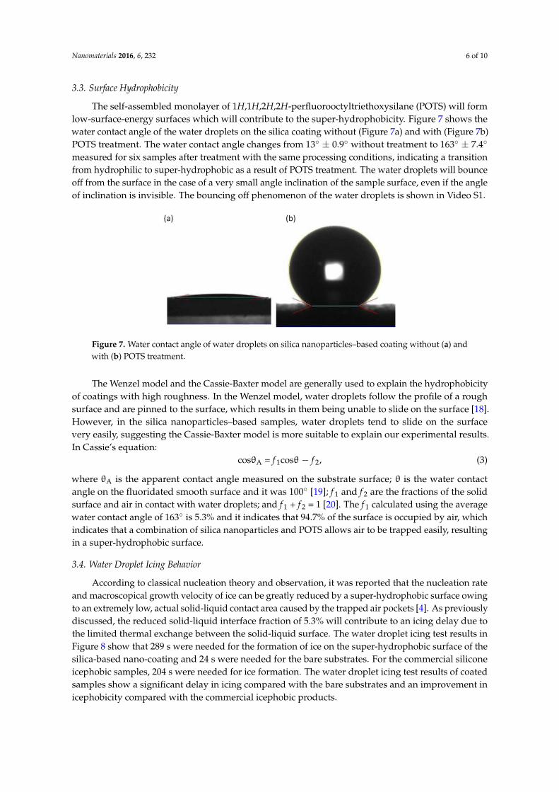
The self-assembled monolayer of 1H,1H,2H,2H-perfluorooctyltriethoxysilane (POTS) will formlow-surface-energy surfaces which will contribute to the super-hydrophobicity. Figure 7 shows thewater contact angle of the water droplets on the silica coating without (Figure 7a) and with (Figure 7b)POTS treatment. The water contact angle changes from 13◦ ± 0.9◦ without treatment to 163◦ ± 7.4◦
measured for six samples after treatment with the same processing conditions, indicating a transitionfrom hydrophilic to super-hydrophobic as a result of POTS treatment. The water droplets will bounceoff from the surface in the case of a very small angle inclination of the sample surface, even if the angleof inclination is invisible. The bouncing off phenomenon of the water droplets is shown in Video S1.
Nanomaterials 2016, 6, 232 6 of 9
water contact angle of the water droplets on the silica coating without (Figure 7a) and with (Figure
7b) POTS treatment. The water contact angle changes from 13° ± 0.9° without treatment to 163° ± 7.4°
measured for six samples after treatment with the same processing conditions, indicating a transition
from hydrophilic to super-hydrophobic as a result of POTS treatment. The water droplets will bounce
off from the surface in the case of a very small angle inclination of the sample surface, even if the
angle of inclination is invisible. The bouncing off phenomenon of the water droplets is shown in
Video S1.
Figure 7. Water contact angle of water droplets on silica nanoparticles–based coating without (a) and
with (b) POTS treatment.
The Wenzel model and the Cassie-Baxter model are generally used to explain the
hydrophobicity of coatings with high roughness. In the Wenzel model, water droplets follow the
profile of a rough surface and are pinned to the surface, which results in them being unable to slide
on the surface [18]. However, in the silica nanoparticles–based samples, water droplets tend to slide
on the surface very easily, suggesting the Cassie-Baxter model is more suitable to explain our
experimental results. In Cassie’s equation:
cosθA = f1cosθ − f2, (3)
where θA is the apparent contact angle measured on the substrate surface; θ is the water contact angle
on the fluoridated smooth surface and it was 100° [19]; f1 and f2 are the fractions of the solid surface
and air in contact with water droplets; and f1 + f2 = 1 [20]. The f1 calculated using the average water
contact angle of 163° is 5.3% and it indicates that 94.7% of the surface is occupied by air, which
indicates that a combination of silica nanoparticles and POTS allows air to be trapped easily, resulting
in a super-hydrophobic surface.
3.4. Water Droplet Icing Behavior
According to classical nucleation theory and observation, it was reported that the nucleation rate
and macroscopical growth velocity of ice can be greatly reduced by a super-hydrophobic surface
owing to an extremely low, actual solid-liquid contact area caused by the trapped air pockets [4]. As
previously discussed, the reduced solid-liquid interface fraction of 5.3% will contribute to an icing
delay due to the limited thermal exchange between the solid-liquid surface. The water droplet icing
test results in Figure 8 show that 289 s were needed for the formation of ice on the super-hydrophobic
surface of the silica-based nano-coating and 24 s were needed for the bare substrates. For the
commercial silicone icephobic samples, 204 s were needed for ice formation. The water droplet icing
test results of coated samples show a significant delay in icing compared with the bare substrates and an
improvement in icephobicity compared with the commercial icephobic products.
Figure 7. Water contact angle of water droplets on silica nanoparticles–based coating without (a) andwith (b) POTS treatment.
The Wenzel model and the Cassie-Baxter model are generally used to explain the hydrophobicityof coatings with high roughness. In the Wenzel model, water droplets follow the profile of a roughsurface and are pinned to the surface, which results in them being unable to slide on the surface [18].However, in the silica nanoparticles–based samples, water droplets tend to slide on the surfacevery easily, suggesting the Cassie-Baxter model is more suitable to explain our experimental results.In Cassie’s equation:
cosθA = f 1cosθ − f 2, (3)
where θA is the apparent contact angle measured on the substrate surface; θ is the water contactangle on the fluoridated smooth surface and it was 100◦ [19]; f 1 and f 2 are the fractions of the solidsurface and air in contact with water droplets; and f 1 + f 2 = 1 [20]. The f 1 calculated using the averagewater contact angle of 163◦ is 5.3% and it indicates that 94.7% of the surface is occupied by air, whichindicates that a combination of silica nanoparticles and POTS allows air to be trapped easily, resultingin a super-hydrophobic surface.
3.4. Water Droplet Icing Behavior
According to classical nucleation theory and observation, it was reported that the nucleation rateand macroscopical growth velocity of ice can be greatly reduced by a super-hydrophobic surface owingto an extremely low, actual solid-liquid contact area caused by the trapped air pockets [4]. As previouslydiscussed, the reduced solid-liquid interface fraction of 5.3% will contribute to an icing delay due tothe limited thermal exchange between the solid-liquid surface. The water droplet icing test results inFigure 8 show that 289 s were needed for the formation of ice on the super-hydrophobic surface of thesilica-based nano-coating and 24 s were needed for the bare substrates. For the commercial siliconeicephobic samples, 204 s were needed for ice formation. The water droplet icing test results of coatedsamples show a significant delay in icing compared with the bare substrates and an improvement inicephobicity compared with the commercial icephobic products.

Nanomaterials 2016, 6, 232 7 of 10Nanomaterials 2016, 6, 232 7 of 9
Figure 8. Water droplet icing test results.
3.5. Ice Adhesion Strength
Besides the icing delay performance, the ice adhesion strength is another important parameter
for icephobicity. With low ice adhesion strength, the ice can be removed easily which is desirable for
de-icing. It was revealed that the average ice adhesion strength is linearly correlated with 1 + cosθe,
with θe standing for the estimated equilibrium contact angle which implies that a low ice adhesion
strength can be obtained from super-hydrophobic surfaces [1]. In this experiment, the centrifuge
adhesion test method was used to evaluate the ice adhesion strength of silica-based nano-coatings
and aluminium substrates for comparison [16]. From Figure 9, it can be seen that all the measured
shear stresses between the coated samples/glaze ice block were remarkably less than the shear
stresses between the Al substrates/glaze ice block. There are some variations in the ice adhesion
results. For better accuracy, we tested six silica-based coating samples fabricated by the same
formulation. The difference between each sample, especially between samples 5 and 7, might be
caused by natural variability in the shapes of ice blocks. The shear stresses between the ice and the
silica-coated samples are all lower than 100 kPa which is the threshold for icephobicity [21]. It is worth
mentioning that some glaze ice blocks were dropped from the silica-coated sample before the rotation
started showing extremely low ice adhesion strength.
Figure 9. Ice adhesion results of silica-based nano-coatings on Al substrates (samples 2–7) and
untreated Al surface (sample 1).
A strict definition of icephobicity remains unclear. It was suggested that a surface should be
called icephobic if it delays ice formation at temperatures below the freezing point of water and/or if
it has a weak adhesion strength to ice of less than 100 kPa [21]. The bouncing off of incoming water
droplets, the icing delay performance and the low ice adhesion strength show that the super-
hydrophobic coatings based on silica nanoparticles are suitable for use as icephobic coatings
regarding their icephobicity.
3.6. Durability under Impact of Pneumatic Water Impinging
Figure 8. Water droplet icing test results.
3.5. Ice Adhesion Strength
Besides the icing delay performance, the ice adhesion strength is another important parameterfor icephobicity. With low ice adhesion strength, the ice can be removed easily which is desirable forde-icing. It was revealed that the average ice adhesion strength is linearly correlated with 1 + cosθe,with θe standing for the estimated equilibrium contact angle which implies that a low ice adhesionstrength can be obtained from super-hydrophobic surfaces [1]. In this experiment, the centrifugeadhesion test method was used to evaluate the ice adhesion strength of silica-based nano-coatingsand aluminium substrates for comparison [16]. From Figure 9, it can be seen that all the measuredshear stresses between the coated samples/glaze ice block were remarkably less than the shear stressesbetween the Al substrates/glaze ice block. There are some variations in the ice adhesion results.For better accuracy, we tested six silica-based coating samples fabricated by the same formulation.The difference between each sample, especially between samples 5 and 7, might be caused by naturalvariability in the shapes of ice blocks. The shear stresses between the ice and the silica-coated samplesare all lower than 100 kPa which is the threshold for icephobicity [21]. It is worth mentioning thatsome glaze ice blocks were dropped from the silica-coated sample before the rotation started showingextremely low ice adhesion strength.
Nanomaterials 2016, 6, 232 7 of 9
Figure 8. Water droplet icing test results.
3.5. Ice Adhesion Strength
Besides the icing delay performance, the ice adhesion strength is another important parameter
for icephobicity. With low ice adhesion strength, the ice can be removed easily which is desirable for
de-icing. It was revealed that the average ice adhesion strength is linearly correlated with 1 + cosθe,
with θe standing for the estimated equilibrium contact angle which implies that a low ice adhesion
strength can be obtained from super-hydrophobic surfaces [1]. In this experiment, the centrifuge
adhesion test method was used to evaluate the ice adhesion strength of silica-based nano-coatings
and aluminium substrates for comparison [16]. From Figure 9, it can be seen that all the measured
shear stresses between the coated samples/glaze ice block were remarkably less than the shear
stresses between the Al substrates/glaze ice block. There are some variations in the ice adhesion
results. For better accuracy, we tested six silica-based coating samples fabricated by the same
formulation. The difference between each sample, especially between samples 5 and 7, might be
caused by natural variability in the shapes of ice blocks. The shear stresses between the ice and the
silica-coated samples are all lower than 100 kPa which is the threshold for icephobicity [21]. It is worth
mentioning that some glaze ice blocks were dropped from the silica-coated sample before the rotation
started showing extremely low ice adhesion strength.
Figure 9. Ice adhesion results of silica-based nano-coatings on Al substrates (samples 2–7) and
untreated Al surface (sample 1).
A strict definition of icephobicity remains unclear. It was suggested that a surface should be
called icephobic if it delays ice formation at temperatures below the freezing point of water and/or if
it has a weak adhesion strength to ice of less than 100 kPa [21]. The bouncing off of incoming water
droplets, the icing delay performance and the low ice adhesion strength show that the super-
hydrophobic coatings based on silica nanoparticles are suitable for use as icephobic coatings
regarding their icephobicity.
3.6. Durability under Impact of Pneumatic Water Impinging
Figure 9. Ice adhesion results of silica-based nano-coatings on Al substrates (samples 2–7) and untreatedAl surface (sample 1).
A strict definition of icephobicity remains unclear. It was suggested that a surface shouldbe called icephobic if it delays ice formation at temperatures below the freezing point of waterand/or if it has a weak adhesion strength to ice of less than 100 kPa [21]. The bouncing off ofincoming water droplets, the icing delay performance and the low ice adhesion strength show that the

Nanomaterials 2016, 6, 232 8 of 10
super-hydrophobic coatings based on silica nanoparticles are suitable for use as icephobic coatingsregarding their icephobicity.
3.6. Durability under Impact of Pneumatic Water Impinging
When an aircraft flies through the atmosphere, its surfaces may undergo impact fromhydrometeors such as rain, which can adversely affect the structure of the aircraft and reduce thelifecycle of the components [22]. Therefore, the durability performance of the hydrophobic/icephobiccoatings is a critical factor for practical applications in aircrafts. In this experiment, pneumatic waterimpinging was used in the erosion test rig to evaluate the durability. Figure 10 shows the waterimpinging test results for silica-based coatings for the as-prepared sample, after a 30 min test and aftera 60 min test. The super-hydrophobicity remained after the erosion test for 60 min. Although the watercontact angle dropped from 163◦ ± 7.4◦ to 161◦ ± 4.9◦ after the 30 min erosion test and to 153◦ ± 2.6◦
after the 60 min test, the degeneration of hydrophobicity is at a reasonable value, indicating a certaindurability. However, aiming for applications in aerospace, further optimization will be performed toimprove the durability.
Nanomaterials 2016, 6, 232 8 of 9
When an aircraft flies through the atmosphere, its surfaces may undergo impact from
hydrometeors such as rain, which can adversely affect the structure of the aircraft and reduce the
lifecycle of the components [22]. Therefore, the durability performance of the hydrophobic/icephobic
coatings is a critical factor for practical applications in aircrafts. In this experiment, pneumatic water
impinging was used in the erosion test rig to evaluate the durability. Figure 10 shows the water
impinging test results for silica-based coatings for the as-prepared sample, after a 30 min test and
after a 60 min test. The super-hydrophobicity remained after the erosion test for 60 min. Although
the water contact angle dropped from 163° ± 7.4° to 161° ± 4.9° after the 30 min erosion test and to
153° ± 2.6° after the 60 min test, the degeneration of hydrophobicity is at a reasonable value, indicating
a certain durability. However, aiming for applications in aerospace, further optimization will be
performed to improve the durability.
Figure 10. Water contact angle before and after erosion test from water impinging for silica-based
nano-coatings for as-prepared sample, after 30 min test and after 60 min test.
4. Conclusions
Silica nanoparticles were deposited onto glass substrates to form a nanostructured rough surface
with the function of trapping small-scale air pockets. Self-assembled monolayers (SAMs) of
1H,1H,2H,2H-perfluorooctyltriethoxysilane were grafted onto the silica nanoparticle surface by the
chemical vapor deposition method to reduce the surface energy. The morphology, composition, and
functional groups were characterized to reveal the relationship between the characteristics of the
nanocomposite material and the hydrophobicity. An average water contact angle of 163° suggests a
super-hydrophobic surface was obtained on silica nanoparticles with surface modification by SAMs
of POTS. The water droplet icing test results show that the icing formation of silica-based nano-
coatings was significantly delayed compared to bare substrates and commercial icephobic products
due to the existence of the low surface energy and air pockets on the surface. The ice adhesion
strength test results show that the shear stresses between the treated surface/ice block are much lower
than those between the bare substrate/ice block. The icing delay and low ice adhesion strength
suggest icephobic surfaces have been obtained from the super-hydrophobic silica-based coatings. To
evaluate durability, a test rig of erosion from pneumatic water impinging was designed and set up.
The erosion test results show that super-hydrophobicity remained after testing for 60 min. Further
optimization aiming for aircraft applications is in progress.
Supplementary Materials: The following are available online at http://www.mdpi.com/2079-4991/6/12/232/s1,
Video S1: The water droplets bouncing off phenomenon.
Acknowledgments: This work was supported by CleanSky II-EU initiative GAINS (Grant Agreement No:
671398). The work forms a part of the project to develop a suitable icephobic and hydrophobic coating on aircraft
wing surfaces.
Author Contributions: Junpeng Liu, Fang Xu, Kwing-So Choi, and Xianghui Hou were involved in the design
of the experiment, performed the experiments and drafted the manuscript. Zaid A. Janjua and Barbara Turnbull
contributed to the design, set-up, measurement and calculation of the icephobicity performance test. Martin Roe
contributed to the characterization of materials. Each contributor was essential to the production of this work.
Conflicts of Interest: The authors declare no conflict of interest.
Figure 10. Water contact angle before and after erosion test from water impinging for silica-basednano-coatings for as-prepared sample, after 30 min test and after 60 min test.
4. Conclusions
Silica nanoparticles were deposited onto glass substrates to form a nanostructured roughsurface with the function of trapping small-scale air pockets. Self-assembled monolayers (SAMs)of 1H,1H,2H,2H-perfluorooctyltriethoxysilane were grafted onto the silica nanoparticle surface bythe chemical vapor deposition method to reduce the surface energy. The morphology, composition,and functional groups were characterized to reveal the relationship between the characteristics of thenanocomposite material and the hydrophobicity. An average water contact angle of 163◦ suggests asuper-hydrophobic surface was obtained on silica nanoparticles with surface modification by SAMs ofPOTS. The water droplet icing test results show that the icing formation of silica-based nano-coatingswas significantly delayed compared to bare substrates and commercial icephobic products due tothe existence of the low surface energy and air pockets on the surface. The ice adhesion strength testresults show that the shear stresses between the treated surface/ice block are much lower than thosebetween the bare substrate/ice block. The icing delay and low ice adhesion strength suggest icephobicsurfaces have been obtained from the super-hydrophobic silica-based coatings. To evaluate durability,a test rig of erosion from pneumatic water impinging was designed and set up. The erosion test resultsshow that super-hydrophobicity remained after testing for 60 min. Further optimization aiming foraircraft applications is in progress.
Supplementary Materials: The following are available online at http://www.mdpi.com/2079-4991/6/12/232/s1,Video S1: The water droplets bouncing off phenomenon.

Nanomaterials 2016, 6, 232 9 of 10
Acknowledgments: This work was supported by CleanSky II-EU initiative GAINS (Grant Agreement No: 671398).The work forms a part of the project to develop a suitable icephobic and hydrophobic coating on aircraftwing surfaces.
Author Contributions: Junpeng Liu, Fang Xu, Kwing-So Choi, and Xianghui Hou were involved in the design ofthe experiment, performed the experiments and drafted the manuscript. Zaid A. Janjua and Barbara Turnbullcontributed to the design, set-up, measurement and calculation of the icephobicity performance test. Martin Roecontributed to the characterization of materials. Each contributor was essential to the production of this work.
Conflicts of Interest: The authors declare no conflict of interest.
References
1. Meuler, A.J.; Smith, J.D.; Varanasi, K.K.; Mabry, J.M.; McKinley, G.H.; Cohen, R.E. Relationships betweenwater wettability and ice adhesion. ACS Appl. Mater. Interfaces 2010, 2, 3100–3110. [CrossRef] [PubMed]
2. Gent, R.; Dart, N.; Cansdale, J. Aircraft icing. Philos. Trans. R. Soc. Lond. A 2000, 358, 2873–2911. [CrossRef]3. Karunakaran, R.G.; Lu, C.-H.; Zhang, Z.; Yang, S. Highly transparent superhydrophobic surfaces from the
coassembly of nanoparticles (≤100 nm). Langmuir 2011, 27, 4594–4602. [CrossRef] [PubMed]4. Shen, Y.; Tao, J.; Tao, H.; Chen, S.; Pan, L.; Wang, T. Anti-icing potential of superhydrophobic Ti6Al4V
surfaces: Ice nucleation and growth. Langmuir 2015, 31, 10799–10806. [CrossRef] [PubMed]5. Zhang, X.; Shi, F.; Niu, J.; Jiang, Y.G.; Wang, Z.Q. Superhydrophobic surfaces: From structural control to
functional application. J. Mater. Chem. 2008, 18, 621–633. [CrossRef]6. Wang, N.; Xiong, D.; Deng, Y.; Shi, Y.; Wang, K. Mechanically robust superhydrophobic steel surface with
anti-icing, uv-durability, and corrosion resistance properties. ACS Appl. Mater. Interfaces 2015, 7, 6260–6272.[CrossRef] [PubMed]
7. Chane-Ching, K.I.; Lacroix, J.C.; Jouini, M.; Lacaze, P.C. Electropolymerization of hydrophobic dipyrrolyls inaqueous medium based on inclusion chemistry. J. Mater. Chem. 1999, 9, 1065–1070. [CrossRef]
8. Chu, D.; Nemoto, A.; Ito, H. Hydrophobic property of hierarchical polymer surfaces fabricated by precisiontooling machine. J. Polym. Eng. 2014, 34, 477–482. [CrossRef]
9. Esmaeilirad, A.; Rukosuyev, M.V.; Jun, M.B.G.; van Veggel, F. A cost-effective method to create physicallyand thermally stable and storable super-hydrophobic aluminum alloy surfaces. Surf. Coat. Technol. 2016,285, 227–234. [CrossRef]
10. Tien, H.W.; Huang, Y.L.; Yang, S.Y.; Hsiao, S.T.; Liao, W.H.; Li, H.M.; Wang, Y.S.; Wang, J.Y.; Ma, C.C.M.Preparation of transparent, conductive films by graphene nanosheet deposition on hydrophilic or hydrophobicsurfaces through control of the ph value. J. Mater. Chem. 2012, 22, 2545–2552. [CrossRef]
11. Ponja, S.; Sathasivam, S.; Chadwick, N.; Kafizas, A.; Bawaked, S.M.; Obaid, A.Y.; Al-Thabaiti, S.; Basahel, S.N.;Parkin, I.P.; Carmalt, C.J. Aerosol assisted chemical vapour deposition of hydrophobic TiO2-SnO2 compositefilm with novel microstructure and enhanced photocatalytic activity. J. Mater. Chem. A 2013, 1, 6271–6278.[CrossRef]
12. Lin, C.C.; Hsu, S.H.; Chang, Y.L.; Su, W.F. Transparent hydrophobic durable low moisture permeationpoly(fluoroimide acrylate)/SiO2 nanocomposite from solventless photocurable resin system. J. Mater. Chem.2010, 20, 3084–3091. [CrossRef]
13. Li, X.; Du, X.; He, J. Self-cleaning antireflective coatings assembled from peculiar mesoporous silicananoparticles. Langmuir 2010, 26, 13528–13534. [CrossRef] [PubMed]
14. Zhang, F.; Chen, S.; Dong, L.; Lei, Y.; Liu, T.; Yin, Y. Preparation of superhydrophobic films on titanium aseffective corrosion barriers. Appl. Surf. Sci. 2011, 257, 2587–2591. [CrossRef]
15. Xu, L.Y.; Zhu, D.D.; Lu, X.M.; Lu, Q.H. Transparent, thermally and mechanically stable superhydrophobiccoating prepared by an electrochemical template strategy. J. Mater. Chem. A 2015, 3, 3801–3807. [CrossRef]
16. Laforte, C.; Beisswenger, A. Icephobic Material Centrifuge Adhesion Test. In Proceedings of the 11th InternationalWorkshop on Atmospheric Icing of Structures, IWAIS, Montreal, QC, Canada, June 2005; pp. 12–16.
17. Lai, Y.; Lin, C.; Huang, J.; Zhuang, H.; Sun, L.; Nguyen, T. Markedly controllable adhesion of superhydrophobicspongelike nanostructure TiO2 films. Langmuir 2008, 24, 3867–3873. [CrossRef] [PubMed]
18. Yu, S.; Guo, Z.; Liu, W. Biomimetic transparent and superhydrophobic coatings: From nature and beyondnature. Chem. Commun. 2015, 51, 1775–1794. [CrossRef] [PubMed]
19. Pilotek, S.; Schmidt, H.K. Wettability of microstructured hydrophobic sol-gel coatings. J. Sol-Gel Sci. Technol.2003, 26, 789–792. [CrossRef]

Nanomaterials 2016, 6, 232 10 of 10
20. Yang, H.; Deng, Y. Preparation and physical properties of superhydrophobic papers. J. Colloid Interface Sci.2008, 325, 588–593. [CrossRef] [PubMed]
21. Hejazi, V.; Sobolev, K.; Nosonovsky, M. From superhydrophobicity to icephobicity: Forces and interactionanalysis. Sci. Rep. 2013, 3, 2194. [CrossRef] [PubMed]
22. Gohardani, O. Impact of erosion testing aspects on current and future flight conditions. Prog. Aerosp. Sci.2011, 47, 280–303. [CrossRef]
© 2016 by the authors; licensee MDPI, Basel, Switzerland. This article is an open accessarticle distributed under the terms and conditions of the Creative Commons Attribution(CC-BY) license (http://creativecommons.org/licenses/by/4.0/).