super pro avi - kit 300 - autocom pro av1 instructions.pdf · super pro avi - kit 300 it is very...
TRANSCRIPT

Super Pro AVi - Kit 300It is very important that you fully read and understand all of theseinstructions before installation and use.This system is designed for domestic motorcycle use ONLY.
INSTRUCTIONMANUAL andWARRANTY
1006
1155
1149
1238
1307
1528
Super Pro AVi (main control unit)
Complete riders headset type B
Background noise sensor
Rider extension lead
Standard phone lead
Standard music lead
Bike fitting kit
Full Instruction Manual
1179
Kit 300 includes:

CONGRATULATIONSThank you for choosing Autocom. Your Super Pro AVi is designed, built and fully tested to provide you with many years of veryhigh quality use and performance if installed and used as described in these instructions. Please take time to read andunderstand these instructions and feel free to ask your Autocom dealer or call our help line if anything is not perfectly clearand understood. Telephone: +44 (0)1926 431249 (UK)
It is very important to properly set up and use these products as designed. Please do not make any modifications or try to useyour system with any non recommended products or in any other way than described. DO NOT CUT OR MODIFY YOUR HELMETS.
It is common sense and the law in some countries that the rider of a vehicle be in control at all times, which includes the abilityto hear other road users warnings. As such the rider should not have the music volume so loud as to prevent this. Safetyshould always be your first priority and is ultimately the responsibility of the rider. Mounting the system on the bike is normallysafer than having it on your person. Make sure that the quick release connectors are free to quick release in the event of anemergency. Do not fix or tape them together. You should only make adjustments while stationary, never while in motion.Always focus your attention to riding and safety and do not use the system in such a way as to interfere with this. Theadded ability to communicate with your passenger and/or other riders can improve safety, so become familiar with using thesystem to provide good advice and/or warnings etc.
Super Pro AVi is normally sold as Kit 300 (solo) which includes a three part rider’s stereo headset consisting of, a main headsetspeaker harness, plug-in boom microphone and a special plug-in background noise sensor (BGNS). You also get a rider’sheadset extension lead, the main control box with built in power lead, standard phone and stereo music leads, plus a fittingkit that includes various parts to aid most typical types of installation.
Your Super Pro AVi is factory set and so all you need do is install the headset/s and power the main unit to enjoy. If neededyou can easily adjust each headset volume independently or fade the music between headsets, and in some cases you mayneed to slightly adjust the VOX control, but once you have done this the rest is automatic and stunning.
If you know what you are doing, installing the main unit on a typical bike will take about 30 minutes and each headset intoa typical helmet takes about 5 to 20 minutes each, so on average about 1 hour in all, yet on some bikes say with built-instereo music systems that you want to wire into, installation may take an experienced fitter 2 to 5 hours and an inexperiencedfitter may well need the best part of a day. To help with this we are developing a range of helpful kits designed for specificbikes to make installation much quicker and easier, and wherever possible plug and play so please ask your Autocom dealerabout these.
The control box is a specialist high quality audio/communications hub, allowing a rider, to interface with one or two mobilephones, one or two stereo music sources, GPS and/or radar detector, bike-to-bike radio, and/or a passenger etc simply byselecting the optional parts to suit your specific needs. It is designed and sold this way to save you costs as to include all possibleparts/options for every potential way it could be used would not be practical or cost effective. Your Autocom dealer should beable to help you choose what parts you need.
Autocom systems are track tested under extreme speed and noise conditions where they demonstrate highly effectiveperformance. Each part is fully tested before it leaves the factory and set such that most users will simply connect up and usestraight out of the box without the need to make any adjustments, however apart from the external adjusters for individualheadset volume control, front rear music fader and auto VOX level preset adjuster there are also various additional internaladjusters so that you can set and programme the control box to work in various ways allowing for maximum flexibility,however it should be noted that some people may need a little more time or help to get used to the system and some of thelearning curves in particular to the importance of correct microphone and speaker positioning and fine turning, so please bepatient and if in any doubt do not hesitate to ask for help.
If your system is not performing as you would expect or as we claim it should then the most likely cause is incorrect installationor use, in particular microphone and speaker positioning. These instructions have been designed to try to help you get themost out of your system, but if it does not exceed your expectations then we want to help. You are welcome to visit our factoryany time Monday to Friday 09.00 to 17.00, and Saturday mornings by appointment only. If you cannot get to our factory thenplease contact your local dealer or distributor, details available on our website: www.autocom.co.uk
We hope you like this product and enjoy it for many years to come as much as we have enjoyed designing and building itfor you.
Tom Beman MD Autocom Products Ltd
SAFETY TIPS
OVERVIEW
2

Independent Rider Volume Control Colour coded (light green) for easy identification enables the rider to easily set the optimum volume for any conditions,including use with or without earplugs, or even custom moulded in-ear speaker (monitor type) earplugs.
Independent Passenger Volume Control Colour coded (olive green) for easy identification enables the rider to easily set the optimum volume for any conditions,including use with or without earplugs, or even custom moulded in-ear speaker (monitor type) earplugs.
Front/Rear Stereo Fader ControlColour coded (yellow), allows you to adjust the level of audio coming in on Aux 2 and Aux 3 (normally stereo music) betweenrider and passenger.
Automatic Full VOX Control (AF-VOX)The Super Pro AVi is factory set to Automatic VOX operation. You can adjust the level of sensitivity of the VOX and the way itautomatically adjusts by either the position of the background noise sensor within the helmet and/or with the VOX controlknob on the front panel. There is an option to set the VOX to manual level control (better known to Autocom customers aspreset and forget) however this adjustment is internal and so we recommend you consult your Autocom supplier for guidancebefore doing so.
Power L.E.D.Provides visual confirmation of power on.
VOX L.E.D.Aids correct VOX set up by providing visual confirmation of VOX activation.
There are various additional internal adjustment options that we recommend you consult your Autocom dealer or thewww.autocom.co.uk website before attempting to do.
3
SUPER PRO AVi - MAIN CONTROLS
VOX L.E.D.
Aux 3 (normally stereo music)
Aux 2 (normally stereo MP3 phone)
Aux 1 (normally mobile phone)
Aux 4 (normally GPS/radar)
Power L.E.D.
12 volt power lead
Aux 5 (main bike-to-bike lead)
Riders headset lead
Passengers headset lead
VOXControl
Hard
Soft
Pass
enge
r
Ride
r
High Low
High Low
MusicFader
PassengerVolume
RiderVolume
When the arrow pointers on the end of eachcontrol face towards the label it is set to thestandard settings for used without earplugs,with music equal to both rider and passengerand automatic VOX on medium.

4
Riders Headset Lead1200mm long for connecting to the rider’s headset.
Passengers Headset Lead800mm long for connecting to the passenger’s headset. (Option to plug in a 3rd headset).
Power LeadFor connection to the bikes ignition switched fused supply. (Optional two part power lead for mounting in tank bag etc).
Aux 1 Socket (3.5mm x 4 pole)Normally used for mobile phone connection via the lead supplied. Also has switchable power output so that recommendedoptional plug and play Bluetooth phone adaptors can be used and powered directly via this socket. This socket can also beused to interface GPS, radar, bike-to-bike radio or record out using appropriate optional leads.*
Aux 2 Socket (3.5mm x 4 pole)Has automatic volume control and would normally be used for MP3 stereo phone, stereo music, GPS, radar, bike-to-bikeand/or record out using appropriate optional leads.*
Aux 3 Socket (3.5mm x 4 pole)Has automatic volume control and would normally be used for main stereo music input but could be used to interfaceGPS/radar.*
Aux 4 Socket (3.5mm x 4 pole)Would normally be used for GPS and/or radar but could also be used for VOX operated bike-to-bike and/or record out usingappropriate optional leads.*
Aux 5 Socket (60° 5 pole din on fly lead) 300mm longWould normally be used for a wide choice of bike-to-bike transceivers, but could be used to interface GPS, radar or record outusing appropriate optional leads. This socket can power a range of recommended transceivers* and be used for VOX oroptional PTT use.
Aux sockets 1, 2, 3 and 4Can optionally be expanded for two or more connections each and have adjustable output levels.
* Please see matrix below for Functions and Extra Flexibility.
SUPER PRO AVi - CONNECTIVITY
Functions Extra Flexibility
Super Pro AViAux 1
Riderlead
Passengerlead
Aux 1
Aux 2
Aux 3
Aux 4
Aux 5
Normallymobile phone
Normallystereo phone
Normallystereo music
NormallyGPS/radar
Normallybike-to-bike
Additionalnotes for
connection
Optional for1 Bluetooth
headsetadaptor
Autocom7 pin
Autocom7 pin
3.5mm4 pole
3.5mm4 pole
3.5mm4 pole
3.5mm4 pole
Autocom5 pin
60º din
Optional for1 Bluetooth
headsetadaptor
OptionalBluetooth
phoneadaptor
Phone 2
GPS/radar
GPS/radar
GPS/radar
GPS/radar
Bike-to-bike
Bike-to-bike
Bike-to-bike
Rider speech
Passenger speech
Normally phone 1
Normally MP3 phone
Normally stereo music 1
Normally GPS/radar
Normally Bike-to-bike
Adjustable outputs
Record out
Record out
Record out
Record out
50%reduction
50%reduction
50%reduction
50%reduction
Auto VOXtransmit
Auto VOXtransmit
Transmitcut
Auto VOXtransmit
Auto VOXtransmit
100%cut input
(swt 0 or 100%)
100%cut input
(swt 0 or 100%)
100% cutinput
(swt 0 or 100%)plus cut VOX
transmit
Swt0-50%reduce
50%reduction
YesYes N/A Yes Yes
Power out
Power out
Power out
3rd headsetvia optional
Y lead
Auto volume
Auto volume
Switchablepower out for
Bluetoothadaptor
Switchablepower out
Swt0-50%reduce
50%reduction
Additionalnotes for
connection
Can beused foroption 2
Can beused foroption 3
Can beused foroption 4
Can beused foroption 5
Can beused foroption 6
Type ofconnection
Aux 2 Aux 3 Aux 4 Aux 5
Input to
Affects
Affects
Affects
Affects
Affects
Affects
Affects
Stereomusic 2

Having read this manual completely and checked any questions with your dealer, you should now be ready to do a pre-installation test, followed by main control box and headset installations and then final setting up and check.
Pre-installation testBefore fully installing your Super Pro AVi on your bike or in a tank bag etc, carefully think it through. It is easy to do a completeinstallation only to then find a problem and not know the cause or how to resolve it. However, if you follow these instructionsyou should find and cure any problems before and/or during the installation meaning you only need to do it once.
Please note that Super Pro AVi is splash resistant; it is designed not to be completely sealed so as to allow it to breathe. It ishowever internally protected from damp and the odd splash so please consider its location carefully in order to help preventexcessive water contamination. For example, do not position it where water will be forced in under pressure, such as in thefront of the bikes faring, or under a wheel arch etc. Look for locations say under the seat or in a tank bag or wherever youare sure it will not get soaking wet. Of course reasonable care should be taken when washing the bike especially if you use ajet wash. You may cover the control box with a bag etc when washing, but ensure the unit can breathe or you may causedamage if it is allowed to build up excessive condensation.
Lay all the parts out where you think you would like them to go either on the bike where it will least get soaking wet (normallyunder the seat near the rear light cluster ) or perhaps in your tank bag (if you have the optional two part power lead). Thinkabout where the cables will run trying to avoid areas of potential electrical interference, such as HT leads and voltage regulator(normally a metal finned box bolted to the bikes frame) and areas of high heat such as engine and exhaust systems.
Typically if mounting the control unit under the seat the riders lead will come out between the seat and tank (or optionallyfrom the tank bag), and the passenger lead near to the rear of the seat, often close to the passenger grab handles wherefitted. Remember this is only a trial fit at this stage. When you think you have it all figured out, temporarily connect the 12volt lead to a recommended fused ignition switched supply.
Normally you will connect the black (negative) wire directly to the battery negative terminal using the crimped eyeletsupplied as this is the best earth on the bike. Not using the battery earth is the most likely cause for interference issue.Connect the red (Positive) wire to a recommended, switched ignition, fused supply, such as the positive feed to the tail lights,or rear brake light switch and solder the joint. Always ask your bike dealer if you are not completely sure. Please note that youcan split the red and black power cable as required and cut them to length but don’t do this until you make the finalconnection. Do not connect to the brake light circuit if your bike has ABS braking and/or a brake light failurewarning system (consult your bike supplier/ manufacturer for approval before connecting to any ABS brake light circuit orbikes that have CANbus). If connection to the brake light circuit is not recommended, please use some other recommendedfused/ignition switched 12 volt supply, such as the rear tail light live feed or any other recommended point.
Always solder joints wherever possible, as this provides a more professional and reliable connection. Do not use quickconnectors like scotch-locks etc. These are nearly always unreliable and most bike manufacturers condemn their use, whichmay also affect the bikes warranty. You will notice the supplied fitting kit includes items which will assist in installation (e.g.tie wraps, insulation amalgamating tape to cover the soldered positive joint, (again don’t use this for the pre-install test) acrimp type eyelet for connection to battery negative terminal, Velcro to fix the control box and if required also speakers intohelmet). Also consider our optional part 1546 which can help with some installations. For added safety and protection thesystem has reverse polarity protection, which means that it reduces the risk of damage if you accidentally wire the power leadthe wrong way around, however, the unit will not function unless wired correctly. The system also has short circuit and thermaloverload protection. This means that the unit will automatically shut down in the event of being overloaded e.g. incorrecttransceiver used or improper connections.
GETTING STARTED
5
CONNECTING THE POWER LEAD TO THE BIKE

With the main unit in position and ready to power assemble the headset by plugging in the boom microphone andbackground noise sensor and then connect this to the headset extension lead and plug this into the rider’s lead of the maincontrol box. If possible also have a stereo system playing and plugged into the Aux 3 socket using the music lead supplied andthe optional passenger headset if you have chosen one. Make sure that the music fader is in the central position (i.e. pointerfacing the label).
Start the engine (in a well ventilated area) (power L.E.D. should be lit) and wait about 20 seconds and you should hear musicthrough the headset speakers but if not or it is low please check that the music system is plugged in properly and switched onand the volume level is adjusted to about the mid position making sure you are plugged into the headphone socket and nota line out socket of the stereo system. Hold the speakers over your ears and do not worry if the music volume is a bit low asit is being compressed by the automatic volume control circuit (as you are stationary) and you can test this now by blowinghard while making a low frequency growling sound into the background noise sensor (BGNS) which will make the musicvolume suddenly rise and then automatically drop back down soon after stop blowing/growling.
If you position the beige side of the microphone so that it is touching your lips and project your voice positively through it, asif to someone say 15 feet (5 meters) away, you should hear the music level reduce by about 50% and your voice will be heardthrough the speakers, (note the side-tone lets you hear your own voice through your own speakers which helps you to speakat the correct level). Note the VOX L.E.D. lights up. When you stop speaking the VOX will automatically 100% cut themicrophone/s and return the music back to its original level. (VOX light goes off) if you have an optional passenger headsetand lead you should also plug this in to the shorter passenger lead of the control box and test this as you have with the rider’sheadset for speech and music, remembering to vary the engine RPM while listening for any interference, noting that you haveto blow on the riders BGNS in order to hear the music rise on both headsets. Remember to always unplug any leads that arenot being used.
If you are planning on plugging in any other devices such as bike-to-bike, GPS and/or radar detector etc. or one of our specialon-bike music interface leads, now is the best time to connect these up per their instructions and do a pre install test to makesure the sound is clean and clear with each product with the engine running at various RPM. If you do this one item at atime and check for any interference you will hear if any noise is introduced and which device/lead is the cause and so canrelocate that part/lead so that the interference goes away. If it is all ok you are now ready for the next stage.
Top TipsIf while speaking into the microphone you gently move it about while it is just touching your lips you will discover a loud spotwhich produces the most sound level, also note how just a few millimetres (1/8”) movement can effect the level of speech andso your ability to operate the VOX. This is because Autocom’s microphones are true noise cancelling and so you must poweryour voice through one side only. If you do not use the loud spot the level of your voice will be reduced and so you will struggleto operate the VOX or hear at high speeds, especially when using high attenuation earplugs. It is therefore very importantthat you learn about and use this loud spot as the system is tuned to it. Consider that while you are stationary the automaticVOX level automatically drops to its lowest level and so it is at its easiest to speak to and activate. When out on the bike asyou go faster the background noise sensor (BGNS) that is part of the rider’s headset will detect increasing helmet noise andautomatically adjust the VOX level higher to prevent the helmet noise from false triggering the VOX. Of course as the VOXlevel increases you have to speak louder in order to activate it, but you will do this automatically because as you go faster thehelmet noise increases and so you will naturally and automatically speak louder to compensate. As the noise level increases sodoes your voice and so you should always be able to easily speak and operate the VOX so long as you use the microphoneloud spot.
6
FIRST TEST

Having already temporarily positioned and tested the system prior to final installation and moved any parts/leads where required,now all you need do is carefully fix everything into place including routing all cables remembering to avoid areas of high heatsuch as engine and exhaust system and also places of interference such as HT leads, spark plugs and regulator box etc.
Where you route the cables along the frame of the bike etc, secure them as required using tie wraps. Care should be taken toensure that the cables cannot fall into the chain, wheel or foul the steering etc, or be trapped or crushed by the seat or bodypanels. If required use some hard packing strips either side of the cables to prevent damaging the cables at pressure pointssuch as where the cables come from under the seat between the tank and body panels etc, if required bond the packing stripsin place but only after you are sure of the final location. Avoid any sharp angles or edges, which may damage or cut the cables.Pay particular attention to the seat locking mechanism, which, if fouled could cause problems with removing the seat. Whenusing tie wraps please be careful not to over tighten them, taking care to avoid brake-lines, breathers, overflow pipes etc. andwhen you cut the surplus off any tie wraps remember to cut short and square so that it reduces any sharp edges that mayscratch you when servicing or washing the bike.
Top TipAt various stages throughout installing the main control unit please run the engine at various RPM and check for interference.If it is all ok then proceed, if you have any interference at any point then back track and retest and if required relocate and/orreroute the main unit and/or leads as required.
Before installing your headset/s - DO NOT CUT OR MODIFY YOUR HELMETSThe standard headset supplied in the kit is for the rider and is designed to work in most full face, open face and flip fronthelmets. However they were not designed to work with 1⁄2 helmets (chip style) which normally require a longer boom andperhaps some additional padding to mount the speakers over your ears. Please note that open face and some flip fronthelmets will require the optional open face conversion kit (part 1198) to prevent direct wind blast. Replacementconsumable foam speaker covers (part 1197) and replacement consumable microphone coverings (part 1214) are availablefrom your dealer. If your helmet has deep ear indentations and you need to pack your speakers out optional foam speakerpads, (6mm (1⁄4”) part 1203 and (12mm (1⁄2”) part 1204) are available from your dealer. If you wish to use in-ear speaker plugs(often referred to as monitor type earplugs) please see optional part 1187.
Part 1109 (Boom EUB) supplied with this kit is our most universal boom. Suitable for most full face, open face and flip fronthelmets.Part 1110 (Boom ELB) is similar to our part 1109 but is slightly longer for very large heads/helmets.Part 1111 (Boom EFFB) is a short boom designed to Velcro into the helmets chin bar (front fit). This can be useful in some flipfront helmets and some full face helmets, but not normally suitable for open face helmets.
Avoid pressure directly to the front and back of the microphone covers. To move or adjust the microphone please hold it bythe outer edges or rubber neck, making sure that the beige side of the fabric sits flat against your lips, then fine tune thepositioning for the loud spot.
It is essential that you fully understand the importance of microphone and speakers positioning and just how muchof a massive difference it will make to the overall quality and performance of your system. We have already mentioned themicrophone loud spot previously on page 6, but speaker placement is just as important and it can sometime be as little as just6mm (1⁄4”) out of alignment or away from the ears that spoils the full potential of what is available to you.
We strongly recommend that you test the headset first while out of the helmet by holding the speakers firmly over you earswhile listening to good quality music and getting someone to speak to you through the system either via your microphone orthrough the optional passenger headset if you have chosen one. If possible have some pretty loud noise going on in thebackground, perhaps a bike running or other noise even if it’s just a very loud TV, Hi-Fi or vacuum cleaner etc, as this will helpto show you an important principle. You will hear that with music playing through your headset speakers while held directlyover your ears that you can hardly hear any of the noise in the background so long as you have our speakers firmly over yourears. If you lift the speakers away from your ears the sound level reduces as does the bass response and you will start to hearthe background noise. It may take a little extra time and effort getting the speakers right in your helmet but as you can see(or will hear) it is well worth it for the extra quality and performance you gain. Please note; that if you intend using earplugsthen do so for this test, bearing in mind that over attenuating earplugs (more than 25dB) may impair some of the speakersound/quality. If the sound is not as good when you have installed the speakers inside your helmet then you need to fine tunetheir positioning.
MAIN CONTROL UNIT FINAL INSTALLATION
7
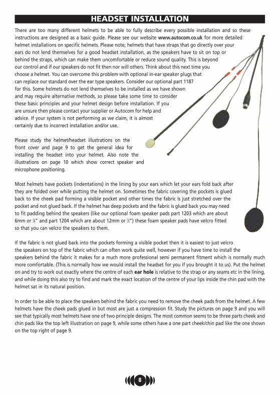
There are too many different helmets to be able to fully describe every possible installation and so theseinstructions are designed as a basic guide. Please see our website www.autocom.co.uk for more detailedhelmet installations on specific helmets. Please note; helmets that have straps that go directly over yourears do not lend themselves for a good headset installation, as the speakers have to sit on top orbehind the straps, which can make them uncomfortable or reduce sound quality. This is beyondour control and if our speakers do not fit then nor will others. Think about this next time youchoose a helmet. You can overcome this problem with optional in-ear speaker plugs thatcan replace our standard over the ear type speakers. Consider our optional part 1187for this. Some helmets do not lend themselves to be installed as we have shownand may require alternative methods, so please take some time to considerthese basic principles and your helmet design before installation. If youare unsure then please contact your supplier or Autocom for help andadvice. If your system is not performing as we claim, it is almostcertainly due to incorrect installation and/or use.
Please study the helmet/headset illustrations on thefront cover and page 9 to get the general idea forinstalling the headset into your helmet. Also note theillustrations on page 10 which show correct speaker andmicrophone positioning.
Most helmets have pockets (indentations) in the lining by your ears which let your ears fold back afterthey are folded over while putting the helmet on. Sometimes the fabric covering the pockets is gluedback to the cheek pad forming a visible pocket and other times the fabric is just stretched over thepocket and not glued back. If the helmet has deep pockets and the fabric is glued back you may needto fit padding behind the speakers (like our optional foam speaker pads part 1203 which are about6mm or 1⁄4” and part 1204 which are about 12mm or 1⁄2”) these foam speaker pads have velcro fittedso that you can velcro the speakers to them.
If the fabric is not glued back into the pockets forming a visible pocket then it is easiest to just velcrothe speakers on top of the fabric which can often work quite well, however if you have time to install thespeakers behind the fabric it makes for a much more professional semi permanent fitment which is normally muchmore comfortable. (This is normally how we would install the headset for you if you brought it to us). Put the helmeton and try to work out exactly where the centre of each ear hole is relative to the strap or any seams etc in the lining,and while doing this also try to find and mark the exact location of the centre of your lips inside the chin pad with thehelmet sat in its natural position.
In order to be able to place the speakers behind the fabric you need to remove the cheek pads from the helmet. A fewhelmets have the cheek pads glued in but most are just a compression fit. Study the pictures on page 9 and you willsee that typically most helmets have one of two principle designs. The most common seems to be three parts cheek andchin pads like the top left illustration on page 9, while some others have a one part cheek/chin pad like the one shownon the top right of page 9.
8
HEADSET INSTALLATION

9
BMW System 4 Helmet InstallationRemove neck collar by pulling the back of the collar away from the helmet andslide both side guides out from retaining locators. Detach Velcro flaps (marked‘A’ below) to expose the polystyrene ear cups.
Thread boom (microphone first) under the chin strap but over the openedVelcro flaps (A). Locate speakers just below the polystyrene ear indents under theVelcro flaps (B).
Neatly tuck speaker cable under lining around the back of the helmet andbelow the neck collar retaining groove, out of sight (C).
Position headset down lead along the outer edge of the helmet under theVelcro flap. This may require addition Velcro to ensure security. Close the Velcroflaps and tidy.
Push the thin section of boom into the joint between the skull and cheek lining,under the chin strap. Locate the boom across the top of left hand cheek padforming it to follow it’s contours. Hold boom down firmly and secure in placewith Velcro or a suitable sticky backed material (D).
Form boom so that microphone is situated in-front of and just touching yourlips in the centre. Check that down lead and boom are well secured and wiresare tidily tucked away. Carefully check the opening and closing of the front ofthe helmet does not snag the boom or down lead.
Test the headset and reposition microphone and speakers if required.Refit neck collar.
Please note that due to the design of this helmet, positioning of the speakers islimited and as such it may not be possible to position the speakers directly inline with your ears. If this is the case one cannot expect the sound to be goodwhen using earplugs.
Step 1Viewed from
underside of Helmetwith chin bar open
and neck collarremoved
Step 2
Passboom
assemblyunder flap
in direction ofarrow
Fit speakers in the earpockets under the
velcroed flaps.
Tuck speaker wire away around theback of the lining underneath the
groove for the neck collar
Step 3
The boom is tuckedtight into groove above
the cheek pad andunder the chinstrap
mounting
Align boom acrossthe top of the
cheek pad
D
View from undersideof Arai type
helmet
Removestraps and lift outeach cheek pad
individually
Boom and Micassembly
Trap Boom (or tape) between cheekpad and outer shell
Return Assembly asremoved
View from undersideof Shoei type
helmet
Removestraps and
lift out complete
Peel back tape and lining, SlideSpeaker inside pushing it right up to
the strap hole
Return Assembly asremoved
Tape to hold in place
Boom and Micassembly
Basic principle of how most helmets are made, come apart andgo back together.
The fabric is either taped orelasticated over the polystyrene andso it is easy to install the speakersbehind the lining. Note that thewire should come out of the speakertowards the back of the helmet.
When replacing the cheek pads,trap the boom betweenthe outer shell and the innercheek pads plastic tongueif it has one. Tape or glue ifrequired. Do not modify thehelmet.

10
Centre ofspeaker
Note that wirenormally comes outtowards back
Centre of earhole
Centre ofear hole �
�Centre ofspeaker
Centre of earhole
Avoid speakernear top of ear
Whichever helmet type you have carefully remove the cheek pads to reveal the back where the fabric is either glued back ortaped back to the polystyrene. Carefully peel the fabric back just enough to slide the speakers into place (normally aboutlevel or just below the level of the hole for the strap and just behind the strap. Try to copy the illustrations on page 9.
If required use some double sided tape or some of the velcro in the kit to help anchor the boom and down lead in to the helmet.
Fitting the Background Noise Sensor (BGNS) within the riders helmet.The BGNS is designed to pick up helmet noise and use this information to automatically adjust both the volume and VOXcontrols of your Super Pro AVi, independently of the main headset microphone/s.
Ideally you want to tuck the BGNS in between the lining and outer shell of the helmet, normally around the back of the ridersneck area, so that it is visible but not hanging out where it may be damaged if accidentally caught or knocked. If the gap istight then carefully use the blunt black plastic instrument supplied in kit 300 to help ease it in to place being careful not todamage the wire or BGNS and remember to plug the BGNS into the main headset harness. Avoid placing the BGNS too closeto the speakers as loud music may affect the auto volume/VOX control and also avoid placing the BGNS too close to yourmouth as this could cause the auto volume/VOX to rise when you are speaking.
Setting the Automatic volume ControlWhen your headset installation is complete turn the VOX control knob on the front panel all the way anti-clockwise to ensure thatthe VOX does not false trigger during this auto volume test, then using the music lead supplied plug a music system into Aux 2 or3 and play some music at a comfortable level through the system while stationary. Ensure the music fader is central. Now go for aride to see how the auto volume responds to varying speeds. If you find the auto volume level goes up too high too early then youneed to attenuate some of the excessive noise getting to the BGNS by either burying it deeper into the helmet lining and/orcovering it with foam or fabric etc. If the music level goes up too late then try to expose the BGNS slightly more to help the noisehave more effect on it earlier. If required it is possible to adjust the BGNS sensitivity using two internal adjusters, but it is normallymuch quicker and easier to just move the BGNS within the rider’s helmet than to get in and make an internal adjustment.
When you are happy with the way the auto volume control is working you can then set the VOX control as follows.
Setting the VOX ControlStart with the VOX control turned all the way clockwise (soft) and go for a ride to see if the helmet noise at speed can false triggerthe VOX. If it does, then slightly turn the VOX control knob anticlockwise say about 1⁄8 of a turn at a time and try it again. Keepdoing this until you have set the VOX such that helmet noise will not accidentally turn it on at speed when you are not speaking.
Top TipYou will not notice any difference in VOX level by adjusting the control knob while stationary. It only affects how the autoVOX level adjusts whilst riding in noise.
You must speak into thebeige side of the microphone

INTERNAL ADJUSTMENT IN YOUR SUPER PRO AVi
11
Warning - we strongly advise you to let your approved Autocom dealer helpyou with any internal adjustments.
Top TipsPlease be vary careful when putting the system back together as it is very easy to accidentally knock switch 7 which couldturn the auto volume control off. You must also be very careful not to trap any wires between the board and the twomounting pillars.
Switch 1 (on/off)When set to “on” as shown(factory setting) any audioinput/s to Aux 4 causes anyinputs to Aux 2 and 3 toautomatically reduce 50%.
Switch 7 (on/off)When set to “off” as shown(factory setting) theautomatic volume controlfor Aux 2 and 3 inputsworks. For manual volumeswitch to “on” and adjustaudio levels manually witheither rider or passengercontrols and/or with musicfader.
Switch 5 (on-A/on-M)Selects auto or manual VOXcontrol. (Factory set to autoVOX as shown). You can finetune the VOX with the VOXcontroller.
Aux 5 audio output adjuster
Aux 4 audio output adjuster
Aux 2 audio output adjuster
Cut or remove this link to stopinputs on Aux 1 causing Aux 2,3 and 5 from being 100% cut,and to stop auto VOX transmitto Aux 4 and 5.
Fit link for 9 volts out on Aux 1
Fit link for 9 volts out on Aux 3
Auto volume control steps 3and 4. We recommend dealersupport
Auto volume control steps 1and 2. We recommend dealersupport
Aux 1 audio output adjuster
Please note; all adjusters are shown as set to factory settings which suit most users preferences. it is recommended that youconsult your dealer before attempting to make any internal adjustments.

If your supplier has not given advice or demonstration on how to setup or use our products, please check with them before sending any
goods back for warranty.
All Autocom products are warranted for a period of 12 months from the date oforiginal purchase, to the original purchaser, from an authorised Autocom retailer. This
warranty covers faulty materials or workmanship, subject to the goods being used only asstated, and only for the purpose as described in the instruction manuals.
No manufacturer's warranty applies to the goods where they are used for any other purpose or inany other way than is explained in the instructions. Nor where the goods have been subjected to
misuse, neglect or accidental damage, or used with any other vendor’s products, including incorrectmechanical or electrical installation, or where the goods have been repaired, modified or altered, without
the manufacturer’s written authorisation.
The manufacturer's warranty is limited to the goods being returned pre paid to the manufacturer's factory,with the original packaging and the original proof of purchase date. The goods must be intact for our
examination.
Where goods are accepted by the manufacturer, under the terms of the warranty, they will be repaired free ofcharge or replaced (at the option of the manufacturer). Where the goods are returned as faulty and are foundnot to be, a charge will be payable to cover costs of inspection, testing, packing and return postage.
This warranty does not cover any consumable items such as batteries, replaceable hygiene foam coveringsfor speakers and microphones, or any other items that are described within the instruction manuals as beinga consumable.
The manufacturer's warranty does not affect your statutory rights.
PLEASE CONTACT YOUR SUPPLIER OR AUTOCOM FOR ANY FURTHER HELP OR INFORMATION.
UK Manufacturer and DistributorAutocom Products Ltd.
Unit 4, Tachbrook Link, Tachbrook Park Drive, Warwick CV34 6RH England.Telephone: +44 (0)1926 431249 (10 lines) Fax: +44 (0)1926 431250 Email: [email protected] Website: www.autocom.co.uk
Warranty
www.autocom.co.uk
We service what we makeFor details of Autocom’s International distributors and support network, please see our website