supercap rotary actuator - controls traders · gk24a-1 supercap rotary actuator with emergency...
TRANSCRIPT
www.belimo.com T2-GK24A-1 • en • v1.1 • 03.2012 • Subject to changes 1 / 4
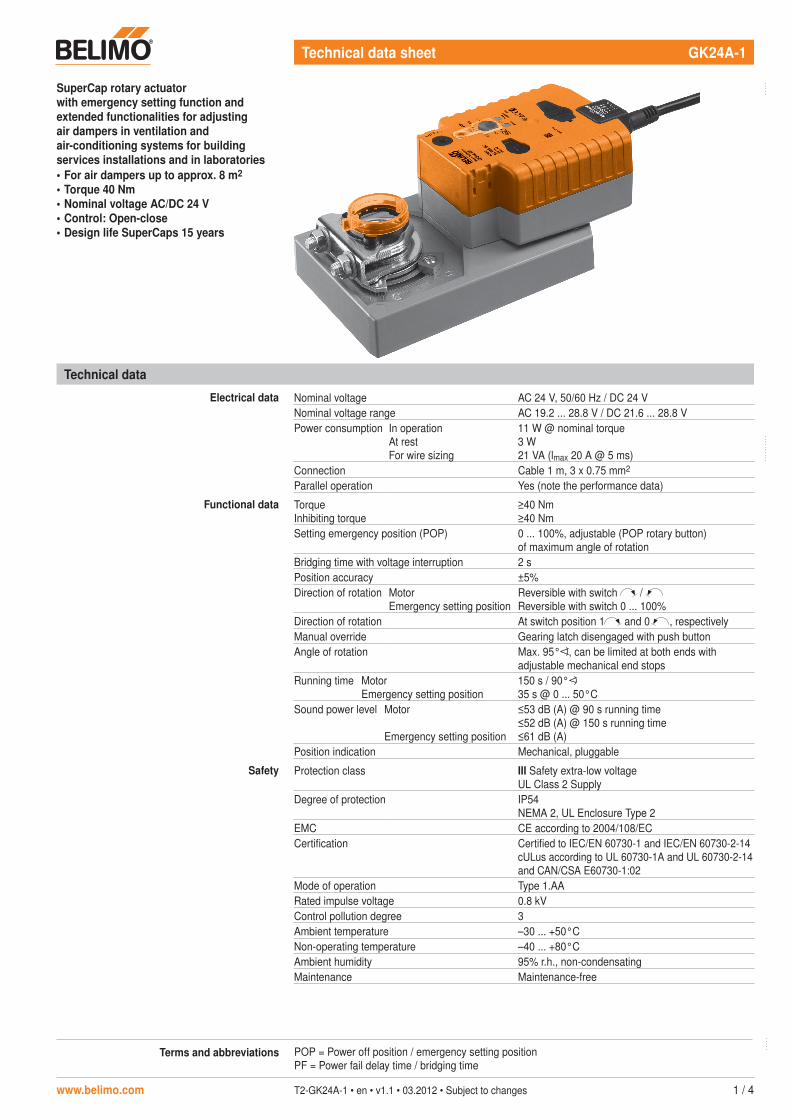
Technical data sheet GK24A-1
Technical data
Electrical data Nominal voltage AC 24 V, 50/60 Hz / DC 24 VNominal voltage range AC 19.2 ... 28.8 V / DC 21.6 ... 28.8 VPower consumption In operation
At restFor wire sizing
11 W @ nominal torque3 W21 VA (lmax 20 A @ 5 ms)
Connection Cable 1 m, 3 x 0.75 mm2
Parallel operation Yes (note the performance data)
Functional data TorqueInhibiting torque
≥40 Nm≥40 Nm
Setting emergency position (POP) 0 ... 100%, adjustable (POP rotary button)of maximum angle of rotation
Bridging time with voltage interruption 2 sPosition accuracy ±5%Direction of rotation Motor
Emergency setting positionReversible with switch / Reversible with switch 0 ... 100%
Direction of rotation At switch position 1 and 0 , respectivelyManual override Gearing latch disengaged with push buttonAngle of rotation Max. 95° , can be limited at both ends with
adjustable mechanical end stopsRunning time Motor
Emergency setting position150 s / 90°35 s @ 0 ... 50°C
Sound power level Motor
Emergency setting position
≤53 dB (A) @ 90 s running time≤52 dB (A) @ 150 s running time≤61 dB (A)
Position indication Mechanical, pluggable
Safety Protection class III Safety extra-low voltageUL Class 2 Supply
Degree of protection IP54NEMA 2, UL Enclosure Type 2
EMC CE according to 2004/108/ECCertification Certified to IEC/EN 60730-1 and IEC/EN 60730-2-14
cULus according to UL 60730-1A and UL 60730-2-14and CAN/CSA E60730-1:02
Mode of operation Type 1.AARated impulse voltage 0.8 kVControl pollution degree 3Ambient temperature –30 ... +50°CNon-operating temperature –40 ... +80°CAmbient humidity 95% r.h., non-condensatingMaintenance Maintenance-free
SuperCap rotary actuator with emergency setting function and extended functionalities for adjusting air dampers in ventilation and air-conditioning systems for building services installations and in laboratories• For air dampers up to approx. 8 m2
• Torque 40 Nm• Nominal voltage AC/DC 24 V• Control: Open-close• Design life SuperCaps 15 years
. . . . .
. . . . . . . . . .
. . . . .Terms and abbreviations POP = Power off position / emergency setting positionPF = Power fail delay time / bridging time

GK24A-1 SuperCap rotary actuator with emergency setting function, AC/DC 24 V, 40 Nm
2 / 4 T2-GK24A-1 • en • v1.1 • 03.2012 • Subject to changes www.belimo.com
Safety notes
!• The actuator is not allowed to be used outside the specified field of application, especially in
aircraft or in any other airborne means of transport.• It may only be installed by suitably trained personnel. Any legal regulations or regulations
issued by authorities must be observed during installation.• The device may only be opened at the manufacturer's site. It does not contain any parts that
can be replaced or repaired by the user.• The cable must not be removed from the device.• The device contains electrical and electronic components and is not allowed to be disposed
of as household refuse. All locally valid regulations and requirements must be observed.
Product features
Mode of operation The actuator moves the air damper to the desired operating position at the same time as the integrated capacitors are loaded (open-closed). Interrupting the supply voltage causes the air damper to be rotated to the selected emergency setting position (POP) by means of stored electrical energy.
Pre-charging time (start up) The capacitor actuators require a pre-charging time. This time is used for charging the capacitors up to a usable voltage level. This ensures that, in the event of an electricity interruption, the actuator can be moved at any time from its current position into the preset emergency setting position (POP).The duration of the pre-charging time depends mainly on how long the power was interrupted.
Typical pre-charging times
0
0
5
10
15
20
25
30
0
5
10
15
20
25
30
2 4 6 8 10 12
Delivery condition (capacitors) The actuator is completely discharged after delivery from the factory, which is why the actuator requires approximately 20 s pre-charging time before initial commissioning in order to bring the capacitors up to the required voltage level.
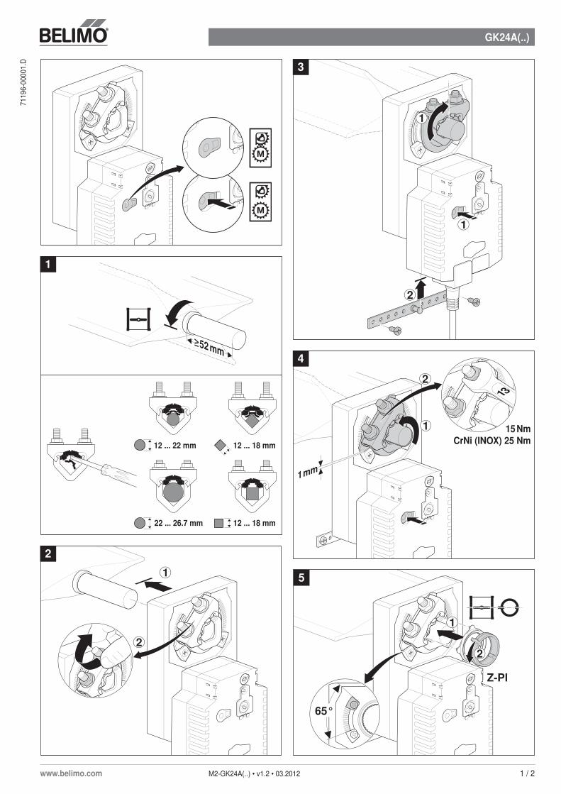
Simple direct mounting Simple direct mounting on the damper spindle with a universal spindle clamp, supplied with an anti-rotation strap to prevent the actuator from rotating.
Manual override Manual override with push button possible (the gear is disengaged for as long as the button remains pressed down).
High operational reliability The actuator is overload-proof, requires no limit switches and automatically stops when the end stop is reached.
Home position / Start The spindle clamp of the actuator is set ex-works to 0°. eingestellt.After the supply voltage has been applied, the actuator moves into the selected position.
Pre-
char
ging
tim
e [ s
]
Duration of voltage interruption [Days]
Technical data (continued)
Dimensions / Weight Dimensions See «Dimensions» on page 4Weight Approx. 1.8 kg
Duration of voltage interruption[Days]
0 1 2 7 ≥10Pre-charging
time [s] 6 9 11 16 20
GK24A-1 SuperCap rotary actuator with emergency setting function, AC/DC 24 V, 40 Nm
www.belimo.com T2-GK24A-1 • en • v1.1 • 03.2012 • Subject to changes 3 / 4
Notes• Connection via safety isolation transformer.• Parallel connection of other actuators possible.
Note the performance data.
!
Accessories
Description Data sheet
Electrical accessories Auxiliary switch S..A.. T2 - S..A..Feedback potentiometer P..A.. T2 - P..A..Adapter Z-SPAIt is imperative that this adapter be ordered if an auxiliary switch or a feedback potentiometer is required and if at the same time the shaft adapter is installed on the rear side of the actuator (e.g. with short-spindle installation).
Mechanical accessories Various accessories T2 - Z-GM..A../GK..A..
Product features (continued)
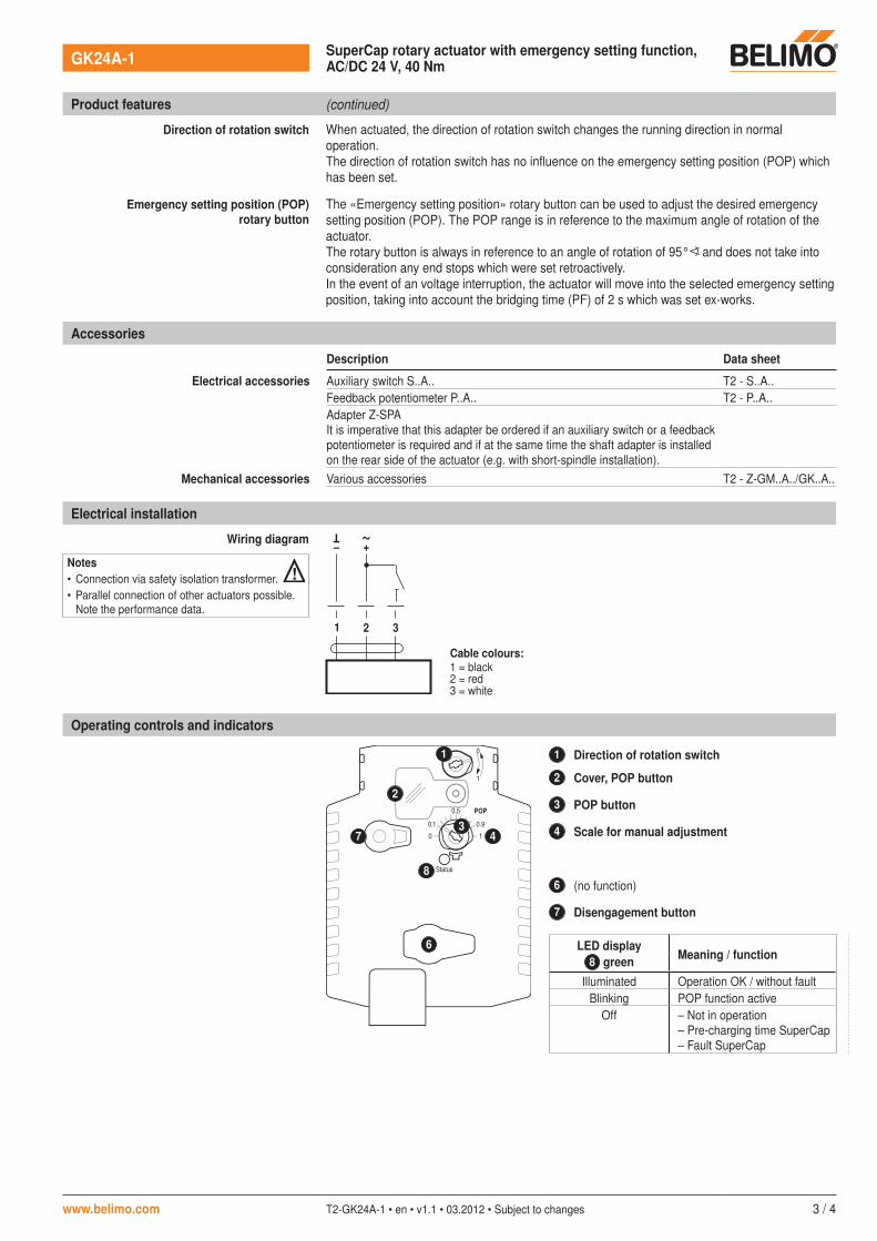
Direction of rotation switch When actuated, the direction of rotation switch changes the running direction in normal operation. The direction of rotation switch has no influence on the emergency setting position (POP) which has been set.
Emergency setting position (POP) rotary button
The «Emergency setting position» rotary button can be used to adjust the desired emergency setting position (POP). The POP range is in reference to the maximum angle of rotation of the actuator.The rotary button is always in reference to an angle of rotation of 95° and does not take into consideration any end stops which were set retroactively.In the event of an voltage interruption, the actuator will move into the selected emergency setting position, taking into account the bridging time (PF) of 2 s which was set ex-works.
Electrical installation
Wiring diagram
1 2 3
– +
T ~
Cable colours:1 = black2 = red3 = white
Operating controls and indicators
Status
100.1
0.5
1
0
0.9
POP
1 Direction of rotation switch
2 Cover, POP button
3 POP button
4 Scale for manual adjustment
6 (no function)
7 Disengagement button
LED displayMeaning / function8 green
Illuminated Operation OK / without fault Blinking POP function active
Off – Not in operation– Pre-charging time SuperCap– Fault SuperCap
6
7
1
2
34
8
. . . . . . . . . . . . . . . . . . . . . . . . . . . . . . . . . . . . . . . . .

GK24A-1 SuperCap rotary actuator with emergency setting function, AC/DC 24 V, 40 Nm
4 / 4 T2-GK24A-1 • en • v1.1 • 03.2012 • Subject to changes www.belimo.com
Operating controls and indicators (continued)
Setting the POP Power off position
100.1
0.5
0.9
100.1
0.5
0.9
100.1
0.5
0.9 POP %0...100
Status
100.1
0.5
1
0
0.9
POP
10
Dimensions [mm]
Dimensional drawings
179
210
60
87
17436
116
99
Damper spindle Length≥52 12 ... 26.7 ≥12 ≤25.5
* ≥20 12 ... 26.7 ≥12 ≤25.5
12 ... 22 mm 12 ... 18 mm
22 ... 26.7 mm 12 ... 18 mm
* When an auxiliary switch or a feedback potentiometer is used, see «Accessories»
GK24A(..)
www.belimo.com M2-GK24A(..) • v1.2 • 03.2012 1 / 2
7119
6-00
001.
D
≥ 52 mm
2
1
1
1 mm
13
15 NmCrNi (INOX) 25 Nm
2
1
2
1
65°
Z-Pl
1
2
1
3
4
2
5
12 ... 22 mm 12 ... 18 mm
22 ... 26.7 mm 12 ... 18 mm
GK24A(..)
2 / 2 M2-GK24A(..) • v1.2 • 03.2012 www.belimo.com
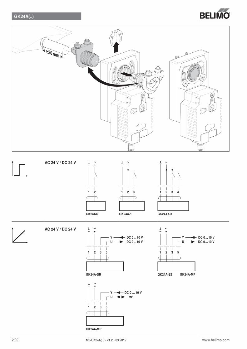
≥ 20 mm
AC24V/DC24V
1 2
– +
T ~1 2
– +
T ~3 1 2
T ~3 4
GK24AX GK24A-1 GK24AX-3
AC24V/DC24V
1 32 5
– +
T ~
Y DC 0 ... 10 V U DC 2 ... 10 V
1 32 5
– +
T ~
Y DC 0 ... 10 V U DC 0 ... 10 V
GK24A-SR GK24A-SZ GK24A-MF
Y U
1 32 5
–
T ~
+
DC 0 … 10 V MP
GK24A-MP