superconducting undulator (scu) r&d motivation and status p. emma for the scu r&d...
TRANSCRIPT

SuperConducting Undulator (SCU) R&DMotivation and Status
P. EmmaFor the SCU R&D collaboration: ANL, LBNL, SLAC
June 27, 2014

Kicking the Can Down the Road (SCU’s)…
Proposed by E. Gluskin in 1999 for LCLS-I “not ready for SCU” (15 yrs ago)
Re-baseline LCLS-II HXR undulator and greatly improve performance (to 8 keV)?
SCU’s operating in ANKA (2005) & APS (2013) right now
Need to be developed now for future FELs (and LCLS-II ?)

Superconducting Undulator Motivation
Using an SCU for the LCLS-II HXR undulator…
Allows full LCLS-II performance to 5 keV+ (SASE & self-seeded) and with 50 m less undulator (or more taper)More aggressive design may allow 8 keV in LCLS-II at 1 MHzHas orders of mag. less sensitivity to radiation dose (1 MHz!)Is much less sensitive to e- emittance (new high-rate gun)Produces very low pressure in a small vacuum chamber (gas scattering at 1 MHz)Enhances LCLS-I FEL power, whereas a new PMU degrades itProvides a better base for LCLS-II upgrades long into the future (e.g., 10 keV at 4.8 GeV)

SCU R&D Plan
ANL…Build 2-m test cryostat (based on existing APS design)Build & test 1.5-m long NbTi prototype planar undulator (lu 21 mm)
LBNL…Build & test 1.5-m long Nb3Sn prototype planar undulator (lu 19 mm)
Measure, correct, and tune both undulators (+ short test cryostat at LBNL)
Both Labs…Develop field measurement and field correction techniquesDemonstrate predicted field, field quality, end-field corrections, field measurement and tuning, cold mass fiducialization, and integration of cold mass into cryostatDevelop conceptual design for 140-m SCU for LCLS-II?
Goal: Within 18 months (July 2015) deliver 2 fully functional, 1.5-m long, SC prototype undulators which meet LCLS-II specificationsWhite paper on possible LCLS-II SCU (by Jan. 2015?)

Undulator Parameters
ANL LNBL
Based on at least 1200 - 5000 eV in LCLS-II at 4 GeV

Brief Status
Requirements laid out for each undulatorMagnet Design Review held June 6 (2 magnets & 1 cryostat)Designs are quite advanced (LBNL action items on cryo connections and 2nd support frame)Correctors and end-field terminations are designedCryostat procurement in process (both labs)ANL cryostat assembly starts in January 2015 (ahead of schedule)Will hold “next phase” meeting July 8 to discuss conceptual design of 140-m system (cold breaks, alignment, cryo, etc)

SCU’s Provide Real Performance Enhancement
SCU (Nb3Sn)
SCU (NbTi)
PMU (NdFeB)
PMU (in-vac)
gap = 7.5 mm (5.7 mm for in-vac same stay-clear)
SCU much higher field for given period, lu, and gap
LCLS-II PMU:lu = 26 mmBpk = 1.0 Tgap = 7.2 mm

Undulator Length vs. e- Energy for LCLS-II HXR
PM
In-VacNbTiNb3 Sn
lu = 27.5 mm, 24.8 mm, 20.3 mm, 18.7 mm (4 GeV)
1.2 - 4.0 keVSelf-Seeded (SS)
l u =
16.
3 m
m
l u =
20.
3 m
m
l u =
18.
7 m
m
g = 7.5 mmge = 0.45 mmIpk = 1 kAsE = 500 keVb = 15 m
Period varies with energy to maintain lower-limit tuning range (1.2 keV)65 m
5.7 mm stay-clear in all cases

PMU(gm = 7.2 mm)
PMU(gm = 6.3 mm)
NbTiNb3Sn
Possible HXU for LCLS-II (toward 8 keV SASE)
Nb3Sn(E = 4.2 GeV)
SASE onlyE = 4.0 GeVge = 0.40 mmIpk = 1 kAsE = 500 keVb = 16 m20% Lu margin3.4-m seg’s1.0-m breaks1 und. missing1.5 keV low-lim.
* 4.0-mm vacuum chamber stay-clear in all cases (except PMU=5)
8 keV
lu = 24.4 mm, 25.6 mm, 18.4 mm, 16.8 mm (op. point)
145-m limit
gm = 6.3 mm*
Cu linac still produces 1-25 keV with slightly better power
~7 keV HXRSS limit

Upgrading to 10 keV (4.8 GeV)
10 keV145-m limit
Nb3Sn(E = 4.2 GeV)
Nb3Sn(E=4.8 GeV)
ge = 0.40 mmIpk = 1 kAsE = 500 keVb = 16 m20% Lu margin3.4-m seg’s1.0-m breaksSASE only1 und. missing
gm = 6.3 mm*
2.1 keV lower limit at 4.8 GeV PMU at 26-mm per. provides 6.5 keV SASE at 4.8 GeV
8.3 keV HXRSS limit

Resistive-Wall Wake Amplified by Smaller Chamber(may reduce photons by factor < 2, but still 8 keV with ~1 GW)
full chamber gap = 5 mm
AluminumRectangular100-m long8-fs relax-timesc = 3.6E7 W-m
2r
2r
full chamber gap = 4 mm
100 pC

“TW-FEL” with SCU’s at SLAC (LCLS-II)?
Parameters LCLS-II SCU(new FEL) unit
X-ray pulse rate 120 Hz Photon energy 4 keV Cu linac energy 15 GeV Peak current 5 kA Beam emittance 0.4 um Bunch charge 150 pC Core bunch length (FWHM) 20 fs Undulator period (Nb3Sn) 24 mm Undulator field (7 mm gap) 3 Tesla FEL gain length 1.3 m Saturation power 100 GW Power after taper 1 TW Pulse energy 20 mJ Photon flux 3×10¹³ photons Undulator length 90 m
Z. Huang
“20-20-20” - 20 mJ in 20 fs in 2020

Magnetic Gap Calculation (April 15, 2014)
Y. Ivanyushenkov

Undulator Tolerances (Nb3Sn & NbTi, 4 GeV & 15 GeV)H.-D. Nuhn

LBNL Design (Nb3Sn)

LBNL - Termination Coils• Odd number of poles (8x7 = 56)• Ideal end design used for main coil: 1/8, 1/2, 7/8

LNBL - Undulator Assembly Components

ANL - New Coil Winding Scheme
Short Test Cores

ANL - End-Coil Winding Scheme

ANL - Measured By and 1st Field Integrals at 500 A
Plot shows effects of compensation coils operated over full 100-A range (SCU0).Compensation coils connected in series and energized to: 0, 51, and 100 A.First field integrals are calculated from measured B-field data.
Tolerance:40 G-cm
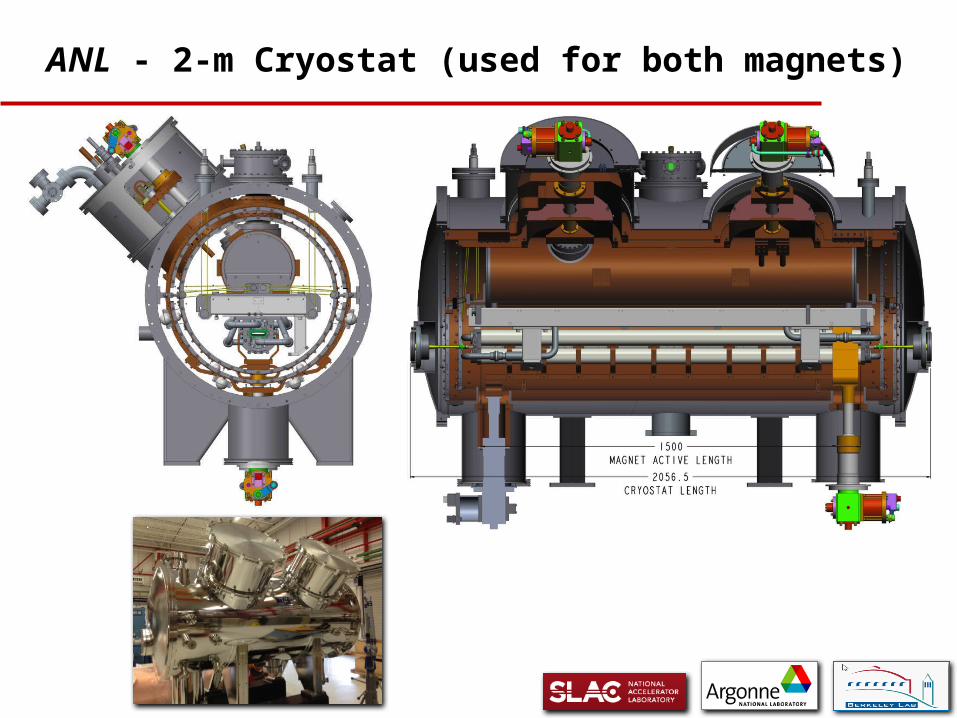
ANL - 2-m Cryostat (used for both magnets)

ANL – He Tank for SCU0 Assembly
Cold-mass support frame might be added to LNBL magnet also (12k$)?

Schedule (rolled up)
magnet testingMarch 2015
completeJuly 2015
magnet reviewJune 2014
start

Budget (FY14 - FY15) with new BES Funds
SLAC funds paid to ANL so far: 636 k$ (of 1920)SLAC funds paid to LBNL so far: 223 k$ (of 526)BES funds paid to ANL so far: 200 k$ (of 400)

Issues for “Next Phase” – Meet July 8
How to join two 1.5-m long sections with minimal space, controlled field integrals, proper phasing?Warm breaks or cold (quads, BPMs, phase shifters, steering coils)?4K Helium transport, cryo power, and distribution?Absolute vertical alignment of undulator with tight (0.05-mm rms at 25 keV) tolerances and cryostat shell?Add alignment quadrupoles to both ends for beam-based alignment at both ends (as at SwissFEL)?Vertical trajectory corrections? (hor. field integrals)Conceptual SCU system design document by Jan. 2015?

LNBL - Summary
One master power supply controls undulator field and three slave supplies provide end corrections.Basic mechanical design completed.– Single piece magnet mandrel– End joint assembly– Mechanical structureReaction and impregnation tooling must be designed but processes are well understoodIntegration with ANL cryostat:– Have maintained same interfaces– Need to finalize the LHe cooling interface– Add cold-mass support frame to LBNL magnet?

ANL - Summary
Magnet structure design and drawings are complete.
Design is based on previous SCU0 and SCU1 magnets.
New coil winding scheme should reduce skew quad.
End-coil compensation same as proven SCU0 design.
Two short magnetic structures have been manufactured and
cold tested.
SCU electrical connection scheme similar to SCU0, with
improvements related to heat transfer.
Procurement of 1.5-m magnet cores begins in August.