superconductivity in graphene-lithium - arxiv · covered graphene and lithium intercalated graphene...
TRANSCRIPT
Superconductivity in Graphene-Lithium
D. M. Guzman∗
School of Materials Engineering, Purdue University,
West Lafayette, Indiana 47907, USA
H. M. Alyahyaei†
Department of Materials Science and Engineering,
University of California, Riverside, California 92521, USA
R. A. Jishi‡
Department of Physics and Astronomy,
California State University, Los Angeles, California 90032, USA
We present first-principles calculations on systems consisting of a few layers of
graphene and lithium. In particular, we investigate the evolution of the electron-
phonon coupling strength with increasing number of layers. We find that, for inter-
calated systems such as C6-Li-C6 or C6-Li-C6-Li-C6, the electron-phonon coupling is
weak. However, for systems of equal number of graphene and lithium layers, such as
C6-Li or C6-Li-C6-Li, the electron-phonon coupling is strong. We investigate the op-
timal configuration that yields the highest superconducting transition temperature.
PACS numbers: 71.15.Mb, 63.22.Rc, 73.22.Pr, 74.78.-w
Keywords: graphene intercalates, electron-phonon coupling, superconductivity.
I. INTRODUCTION
Ever since its discovery, graphene[1] has shown a great potential for applications in
nano-technology[2–5], especially in electronic transport[6]. Studies of superconductivity
in graphite intercalation compounds (GICs)[7–16], recent experimental evidence of a su-
∗Electronic address: [email protected]†Electronic address: [email protected]‡Electronic address: [email protected]; Corresponding author
arX
iv:1
310.
3813
v1 [
cond
-mat
.sup
r-co
n] 1
4 O
ct 2
013
2
perconducting state in graphite-sulfur composites[17, 18], and the growing interest in
superconducting nano-devices[19–21] have motivated theoretical investigation of possible
superconductivity in the two-dimensional graphene systems[22–28]. Single- and few-layer
graphene may exhibit a superconducting state upon adatom deposition or intercalation.
As in the case of alkali-metal and alkaline-earth GICs, superconductivity in modified-
graphene systems can be explained by the electron-phonon coupling enhancement that
arises from the presence of an intercalant-derived band as well as graphitic π-bands at
the Fermi level[12, 29, 30].
Theoretical studies within the density functional theory (DFT) framework were con-
ducted on single- and few-layer graphene systems with intercalated and deposited dopants.
The electron-phonon coupling parameter λ was found to be 0.60 and 0.80, respectively,
in calcium intercalated graphene bilayers and trilayers. The superconducting transition
temperature Tc was estimated to be 4.1 K for Ca-intercalated bilayer and 10.1 K for Ca-
intercalated trilayer[31]. Recently, the possibility of a superconducting state in lithium
covered graphene monolayers was discussed by Profeta et al. [32]. They argued that re-
moval of quantum confinement, in going from LiC6 GIC to Li-covered monolayer graphene,
could bring the Li-derived states down in energy to the Fermi level. This enhances the
electron-phonon coupling strength, making Li-covered single-layer graphene a supercon-
ductor at Tc = 8.1 K.
The recent fabrication of lithium intercalated graphene bilayer [33] raises the question
of whether this two-dimensional material would also exhibit a superconducting state. In
addition, the possibility of a further enhancement of the electron-phonon coupling strength
in few-layer graphene systems intercalated with lithium, remains an open issue.
In this work, we study the effect of increasing number of Li-doped graphene layers
on the electron-phonon coupling strength via first-principles density functional theory.
Details of our methods are presented in Section III. The electronic structure of lithium
covered graphene and lithium intercalated graphene layers is calculated. It is found that
only Li-covered graphene systems exhibit a coexistence of Li-derived s-bands and graphitic
π-bands at the Fermi level. In the case of Li-intercalated graphene systems, the interlayer
band (derived from Li states) is unoccupied. From the vibrational modes and electron-
phonon coupling calculations we find that a significant coupling of electrons to out-of-plane
vibrations is necessary to achieve a significant enhancement of the total electron-phonon
3
coupling strength.
In Section II we describe the crystal structure of the Li-doped graphene systems inves-
tigated in this work, and in Section III details of the methods of calculation are presented.
The results of the electronic structure and vibrational modes calculations are presented
and discussed in Section IV and V, respectively. Conclusions are given in Section VI.
II. CRYSTAL STRUCTURE
Systems consisting of equal numbers of graphene and lithium layers (Li-covered
graphene) and lithium intercalated graphene layers were systematically analyzed from
first-principles. Calculations of the electronic structure and vibrational modes were car-
ried out on systems of up to four lithium and four graphene layers for Li-covered graphene
and up to two lithium and three graphene layers for Li-intercalated graphene layers. In all
the cases considered, the unit cell is a (√
3a×√
3a) R 30◦ supercell of the graphene sheet
unit cell. In agreement with the stage-1 Li-GIC, the carbon layer stacking is taken to be
AAAA. The separation between adjacent carbon and Li layers is set at 1.855 A, similar
to the corresponding value in Li GICs. The in-plane lattice constants are a = b = 4.33 A.
Since the DFT calculations are carried out on a 3-dimensional crystal, the c-lattice con-
stant is taken to be sufficiently large so as to render the system, in effect, two-dimensional.
For systems of the form C6-Li-C6-Li and C6-Li-C6-Li-C6, two stacking configuration for
the Li layers were considered. In one configuration, Li atoms in both layers sit above the
hollow sites of the graphene layer which are labeled α (see Fig. 1). The stackings for C6-Li-
C6-Li and C6-Li-C6-Li-C6 are AαAα and AαAαA, respectively. In this configuration, C6-
Li-C6-Li and C6-Li-C6-Li-C6 will be simply denoted as C6Liαα and C6LiααC6, respectively.
In the other configuration, whereas the Li atoms between the first and second graphene
layers occupy positions labeled α, the Li atoms above the second carbon layer occupy
positions labeled β. In this case, the two Li layers are not directly above each other; the
second layer is shifted, relative to the first, by a lattice vector of the graphene sheet. In
this configuration, the stacking sequence is AαAβ for the Li-covered system, and AαAβA
for the intercalated system. In this configuration, the Li-covered system will be denoted
as C6Liαβ, while the intercalated system will be written as C6LiαβC6.
For structures with three Li layers, two stacking configurations were considered. The
4
first, in which the three Li layers are directly above each other, is AαAαAα. The corre-
sponding system, C6-Li-C6-Li-C6-Li, will be denoted as C6Liααα. In the second configu-
ration, the Li atoms between the first and second graphene layers occupy the hollow sites
labeled α, those between the second and third graphene layers sit in hollow sites labeled
β, and those above the third graphene layer occupy sites labeled γ. The third layer of
Li adatoms is shifted, relative to the second Li layer, by a lattice vector of the graphene
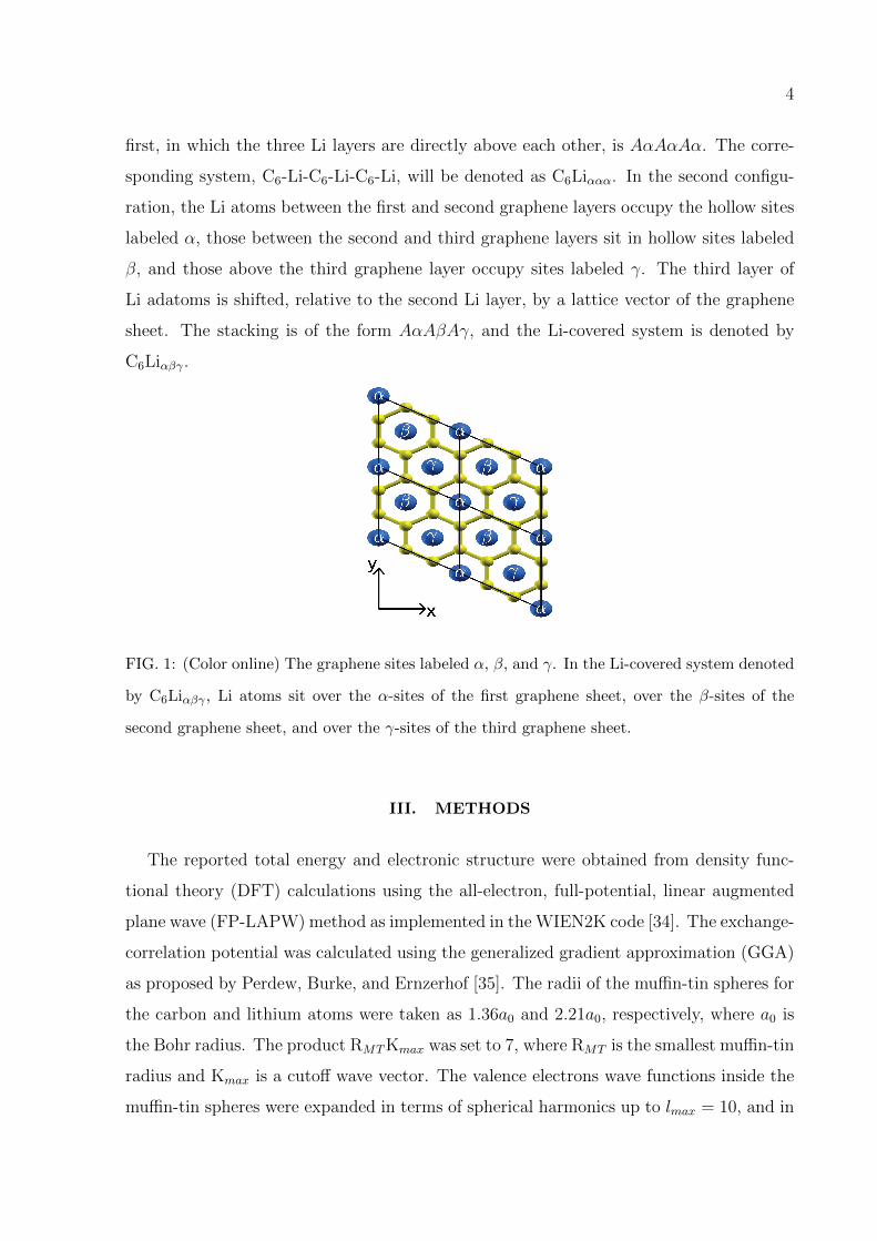
sheet. The stacking is of the form AαAβAγ, and the Li-covered system is denoted by
C6Liαβγ.
FIG. 1: (Color online) The graphene sites labeled α, β, and γ. In the Li-covered system denoted
by C6Liαβγ , Li atoms sit over the α-sites of the first graphene sheet, over the β-sites of the
second graphene sheet, and over the γ-sites of the third graphene sheet.
III. METHODS
The reported total energy and electronic structure were obtained from density func-
tional theory (DFT) calculations using the all-electron, full-potential, linear augmented
plane wave (FP-LAPW) method as implemented in the WIEN2K code [34]. The exchange-
correlation potential was calculated using the generalized gradient approximation (GGA)
as proposed by Perdew, Burke, and Ernzerhof [35]. The radii of the muffin-tin spheres for
the carbon and lithium atoms were taken as 1.36a0 and 2.21a0, respectively, where a0 is
the Bohr radius. The product RMTKmax was set to 7, where RMT is the smallest muffin-tin
radius and Kmax is a cutoff wave vector. The valence electrons wave functions inside the
muffin-tin spheres were expanded in terms of spherical harmonics up to lmax = 10, and in
5
terms of plane waves with a cutoff wave vector Kmax in the interstitial region. The charge
density was Fourier expanded up to a maximum wave vector Gmax = 13a−10 . Conver-
gence of the self-consistent field calculations was attained with a total energy convergence
tolerance of 0.1 mRy and a total charge convergence tolerance of 0.0001 e.
The frequencies of the vibrational modes and the electron-phonon coupling parame-
ter were calculated using the QUANTUM-ESPRESSO[36] package with norm-conserving
pseudopotentials. The valence electrons wave functions and the charge density were ex-
panded in plane waves using 40 Ry and 300 Ry energy cutoffs, respectively. The phonon
frequencies were calculated within the linear-response framework on an 8× 8× 1 phonon-
momentum mesh with a 16×16×1 uniform electron-momentum mesh. For the calculation
of the electronic density of states and the electron-phonon coupling strength, a uniform
40× 40× 1 k-point mesh in the Brillouin zone was used.
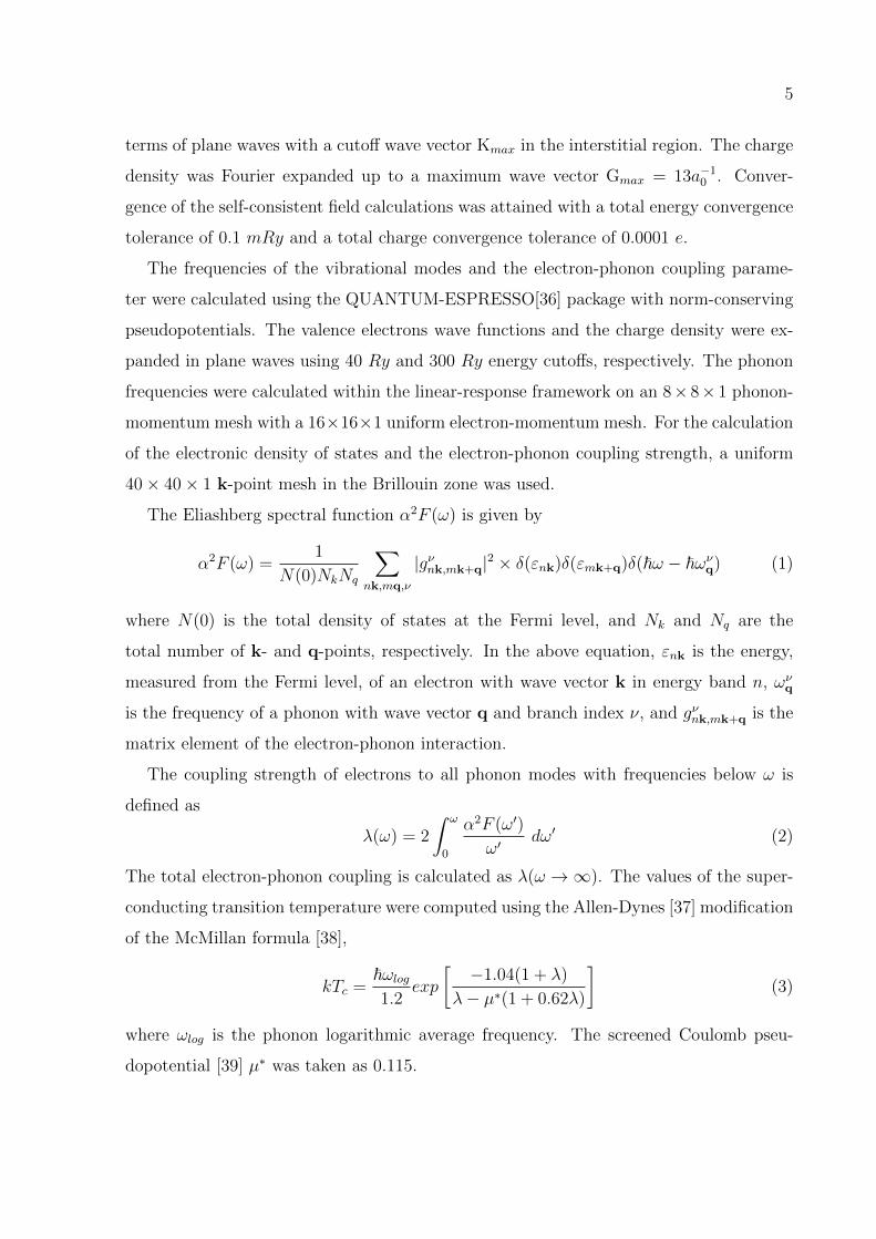
The Eliashberg spectral function α2F (ω) is given by
α2F (ω) =1
N(0)NkNq
∑nk,mq,ν
|gνnk,mk+q|2 × δ(εnk)δ(εmk+q)δ(~ω − ~ωνq) (1)
where N(0) is the total density of states at the Fermi level, and Nk and Nq are the
total number of k- and q-points, respectively. In the above equation, εnk is the energy,
measured from the Fermi level, of an electron with wave vector k in energy band n, ωνq
is the frequency of a phonon with wave vector q and branch index ν, and gνnk,mk+q is the
matrix element of the electron-phonon interaction.
The coupling strength of electrons to all phonon modes with frequencies below ω is
defined as
λ(ω) = 2
∫ ω
0
α2F (ω′)
ω′dω′ (2)
The total electron-phonon coupling is calculated as λ(ω →∞). The values of the super-
conducting transition temperature were computed using the Allen-Dynes [37] modification
of the McMillan formula [38],
kTc =~ωlog1.2
exp
[−1.04(1 + λ)
λ− µ∗(1 + 0.62λ)
](3)
where ωlog is the phonon logarithmic average frequency. The screened Coulomb pseu-
dopotential [39] µ∗ was taken as 0.115.
6
IV. ELECTRONIC STRUCTURE
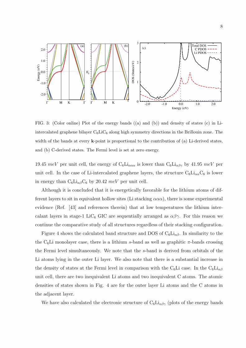
In Figures 2 and 3 we present the energy band dispersion and density of states (DOS) of
lithium-covered graphene layer (C6Li) and lithium-intercalated graphene bilayer (C6LiC6),
respectively. By inspection of the band-structure of C6LiC6, we notice that the interlayer
band (derived from Li states) at the Fermi level is empty, as is the case in stage-1 Li-
GIC, which is not a superconductor. In the case of C6LiC6, the c-direction confinement,
imposed by the top and bottom graphene layers, keeps the interlayer band from being
occupied. As Figure 3a reveals, the bottom of the Li-derived band is ∼ 1.75 eV above
the Fermi energy. Based on these grounds, any further increase in the number of layers
will not create new Li-derived states at the Fermi level.
In the case of Li-covered graphene, we see that the Fermi level is crossed by an s-band
derived from Li states. The removal of the top graphene layer has the effect of bringing
down the energy of the Li-derived band to the Fermi level; this suggests that there is
a partial charge transfer from the Li atoms to the carbon sheet. The amount of charge
transferred from each Li atom is calculated using Bader’s quantum theory of “atoms in
molecules” [40], and the results are presented in Table I. The table reveals that there are
two values of the charge transfer: 0.69 electrons (partial transfer) from an Li atom in the
outer layer, and 0.88 electrons (almost complete transfer) from an Li atom in an inner
layer surrounded by two graphene layers. As in the case of GICs [41], the presence of
an adatom band at the Fermi level increases the number of carriers, promotes electron
coupling to the low energy carbon atoms out-of-plane vibrations, and generates coupling
to the adatom vibrations. [42].
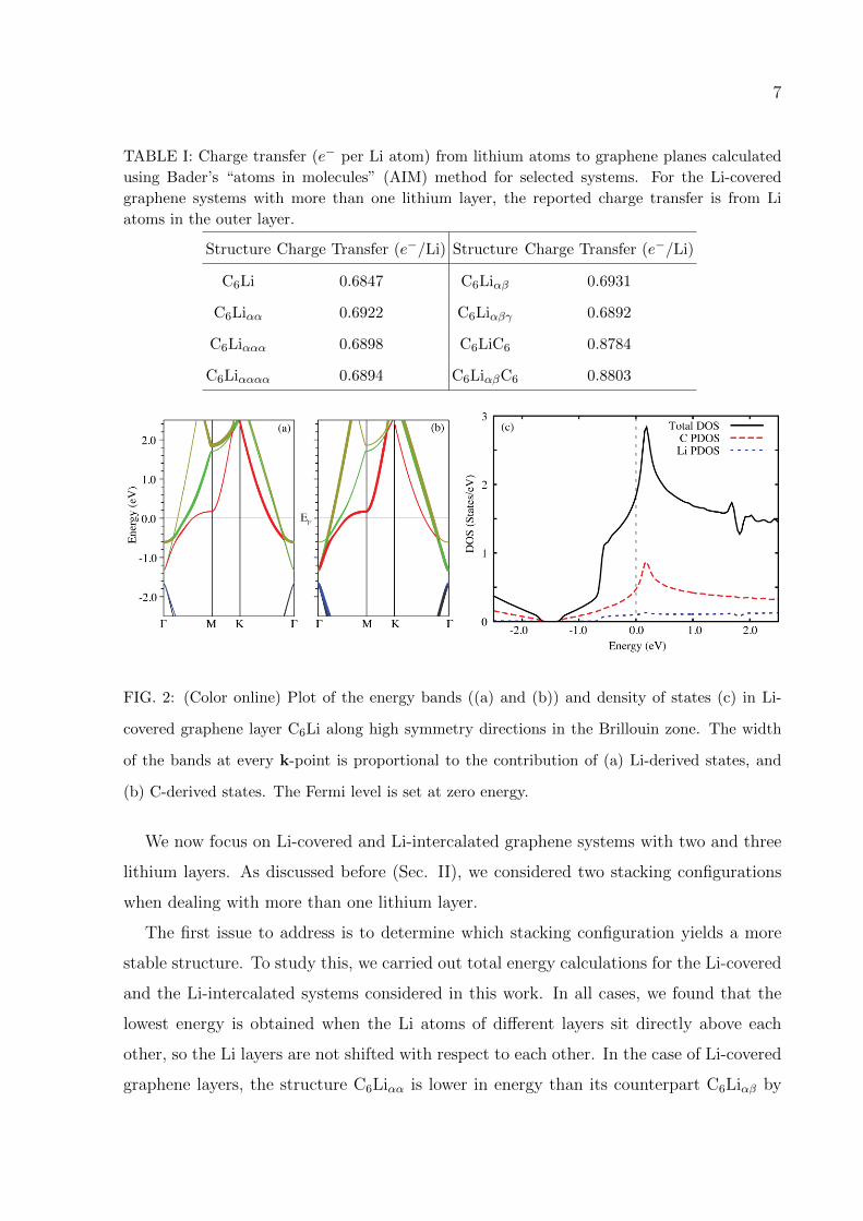
In Figure 2(c) the partial density of states (PDOS) and the total DOS of C6Li are
compared. The total density of states is the sum of the atomic densities of states and the
density of states in the interstitial region. It is important to note that the Li-projected
DOS comes predominantly from the s-band. The LAPW method projects the DOS onto
the muffin-tin spheres, yielding the atomic densities of states; the rest of the total DOS is
assigned to the interstitial region. Figure 2c shows that a substantial portion of the DOS
results from the interstitial region. Since the interstitial space in this structure is mainly
the space between the Li muffin-tin spheres, the contribution of the Li-derived s-band to
the total DOS is comparable to that from the graphitic π bands.
7
TABLE I: Charge transfer (e− per Li atom) from lithium atoms to graphene planes calculated
using Bader’s “atoms in molecules” (AIM) method for selected systems. For the Li-covered
graphene systems with more than one lithium layer, the reported charge transfer is from Li
atoms in the outer layer.
Structure Charge Transfer (e−/Li) Structure Charge Transfer (e−/Li)
C6Li 0.6847 C6Liαβ 0.6931
C6Liαα 0.6922 C6Liαβγ 0.6892
C6Liααα 0.6898 C6LiC6 0.8784
C6Liαααα 0.6894 C6LiαβC6 0.8803
FIG. 2: (Color online) Plot of the energy bands ((a) and (b)) and density of states (c) in Li-
covered graphene layer C6Li along high symmetry directions in the Brillouin zone. The width
of the bands at every k-point is proportional to the contribution of (a) Li-derived states, and
(b) C-derived states. The Fermi level is set at zero energy.
We now focus on Li-covered and Li-intercalated graphene systems with two and three
lithium layers. As discussed before (Sec. II), we considered two stacking configurations
when dealing with more than one lithium layer.
The first issue to address is to determine which stacking configuration yields a more
stable structure. To study this, we carried out total energy calculations for the Li-covered
and the Li-intercalated systems considered in this work. In all cases, we found that the
lowest energy is obtained when the Li atoms of different layers sit directly above each
other, so the Li layers are not shifted with respect to each other. In the case of Li-covered
graphene layers, the structure C6Liαα is lower in energy than its counterpart C6Liαβ by
8
FIG. 3: (Color online) Plot of the energy bands ((a) and (b)) and density of states (c) in Li-
intercalated graphene bilayer C6LiC6 along high symmetry directions in the Brillouin zone. The
width of the bands at every k-point is proportional to the contribution of (a) Li-derived states,
and (b) C-derived states. The Fermi level is set at zero energy.
19.45 meV per unit cell, the energy of C6Liααα is lower than C6Liαβγ by 41.95 meV per
unit cell. In the case of Li-intercalated graphene layers, the structure C6LiααC6 is lower
in energy than C6LiαβC6 by 20.42 meV per unit cell.
Although it is concluded that it is energetically favorable for the lithium atoms of dif-
ferent layers to sit in equivalent hollow sites (Li stacking ααα), there is some experimental
evidence (Ref. [43] and references therein) that at low temperatures the lithium inter-
calant layers in stage-1 LiC6 GIC are sequentially arranged as αβγ. For this reason we
continue the comparative study of all structures regardless of their stacking configuration.
Figure 4 shows the calculated band structure and DOS of C6Liαβ. In similarity to the
the C6Li monolayer case, there is a lithium s-band as well as graphitic π-bands crossing
the Fermi level simultaneously. We note that the s-band is derived from orbitals of the
Li atoms lying in the outer Li layer. We also note that there is a substantial increase in
the density of states at the Fermi level in comparison with the C6Li case. In the C6Liαβ
unit cell, there are two inequivalent Li atoms and two inequivalent C atoms. The atomic
densities of states shown in Fig. 4 are for the outer layer Li atoms and the C atoms in
the adjacent layer.
We have also calculated the electronic structure of C6Liαβγ (plots of the energy bands
9
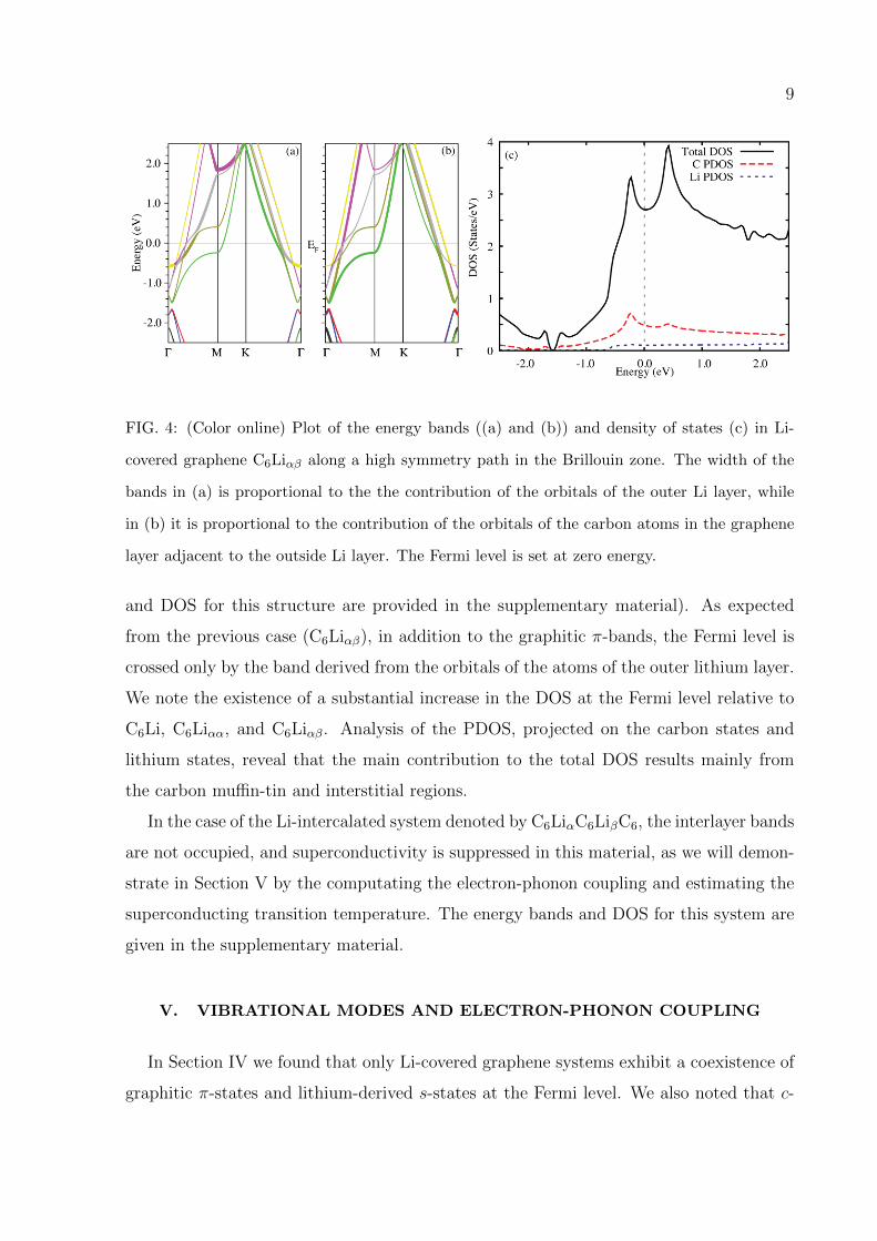
FIG. 4: (Color online) Plot of the energy bands ((a) and (b)) and density of states (c) in Li-
covered graphene C6Liαβ along a high symmetry path in the Brillouin zone. The width of the
bands in (a) is proportional to the the contribution of the orbitals of the outer Li layer, while
in (b) it is proportional to the contribution of the orbitals of the carbon atoms in the graphene
layer adjacent to the outside Li layer. The Fermi level is set at zero energy.
and DOS for this structure are provided in the supplementary material). As expected
from the previous case (C6Liαβ), in addition to the graphitic π-bands, the Fermi level is
crossed only by the band derived from the orbitals of the atoms of the outer lithium layer.
We note the existence of a substantial increase in the DOS at the Fermi level relative to
C6Li, C6Liαα, and C6Liαβ. Analysis of the PDOS, projected on the carbon states and
lithium states, reveal that the main contribution to the total DOS results mainly from
the carbon muffin-tin and interstitial regions.
In the case of the Li-intercalated system denoted by C6LiαC6LiβC6, the interlayer bands
are not occupied, and superconductivity is suppressed in this material, as we will demon-
strate in Section V by the computating the electron-phonon coupling and estimating the
superconducting transition temperature. The energy bands and DOS for this system are
given in the supplementary material.
V. VIBRATIONAL MODES AND ELECTRON-PHONON COUPLING
In Section IV we found that only Li-covered graphene systems exhibit a coexistence of
graphitic π-states and lithium-derived s-states at the Fermi level. We also noted that c-
10
direction confinement produced by the graphene layers push the bands derived from inner
lithium atoms to energies well above the Fermi level. This means that only one Li-derived
band crosses the Fermi level regardless of the number of Li-covered graphene layers. In
addition, the total density of states at the Fermi energy in Li-covered graphene systems
increases as the number of lithium layers increase, a fact that could be relevant for the
enhancement of the electron-phonon coupling strength. However, when the number of Li
layers is large, the Li-covered graphene system, with equal number of Li and graphene
layers, begins to look like stage-1 Li GIC, which is not a superconductor. We conclude
that there is an optimal number of Li layers which leads to the highest possible TC in these
systems. To this end, we present in this section electron-phonon coupling calculations for
various Li-covered graphene systems, as well as the Li-intercalated graphene bilayer.
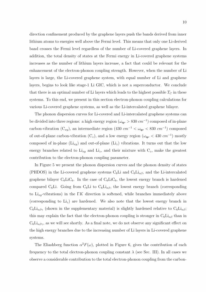
The phonon dispersion curves for Li-covered and Li-intercalated graphene systems can
be divided into three regions: a high energy region (ωqν > 830 cm−1) composed of in-plane
carbon-vibration (Cxy), an intermediate region (430 cm−1 < ωqν < 830 cm−1) composed
of out-of-plane carbon-vibration (Cz), and a low energy region (ωqν < 430 cm−1) mostly
composed of in-plane (Lixy) and out-of-plane (Liz) vibrations. It turns out that the low
energy branches related to Lixy and Liz, and their mixture with Cz, make the greatest
contribution to the electron-phonon coupling parameter.
In Figure 5 we present the phonon dispersion curves and the phonon density of states
(PHDOS) in the Li-covered graphene systems C6Li and C6Liαβ, and the Li-intercalated
graphene bilayer C6LiC6. In the case of C6LiC6, the lowest energy branch is hardened
compared C6Li. Going from C6Li to C6Liαβ, the lowest energy branch (corresponding
to Lixy-vibrations) in the ΓK direction is softened, while branches immediately above
(corresponding to Liz) are hardened. We also note that the lowest energy branch in
C6Liαβγ (shown in the supplementary material) is slightly hardened relative to C6Liαβ;
this may explain the fact that the electron-phonon coupling is stronger in C6Liαβ than in
C6Liαβγ, as we will see shortly. As a final note, we do not observe any significant effect on
the high energy branches due to the increasing number of Li layers in Li-covered graphene
systems.
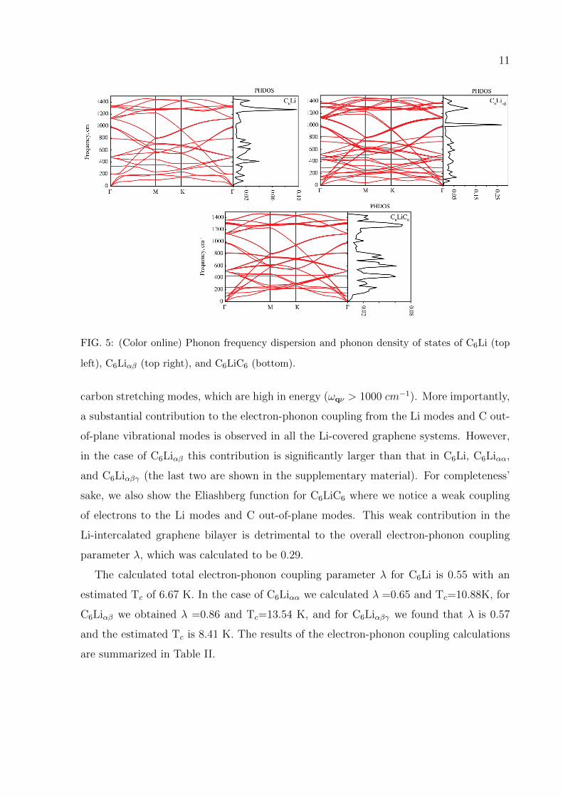
The Eliashberg function α2F (ω), plotted in Figure 6, gives the contribution of each
frequency to the total electron-phonon coupling constant λ (see Sec. III). In all cases we
observe a considerable contribution to the total electron-phonon coupling from the carbon-
11
FIG. 5: (Color online) Phonon frequency dispersion and phonon density of states of C6Li (top
left), C6Liαβ (top right), and C6LiC6 (bottom).
carbon stretching modes, which are high in energy (ωqν > 1000 cm−1). More importantly,
a substantial contribution to the electron-phonon coupling from the Li modes and C out-
of-plane vibrational modes is observed in all the Li-covered graphene systems. However,
in the case of C6Liαβ this contribution is significantly larger than that in C6Li, C6Liαα,
and C6Liαβγ (the last two are shown in the supplementary material). For completeness’
sake, we also show the Eliashberg function for C6LiC6 where we notice a weak coupling
of electrons to the Li modes and C out-of-plane modes. This weak contribution in the
Li-intercalated graphene bilayer is detrimental to the overall electron-phonon coupling
parameter λ, which was calculated to be 0.29.
The calculated total electron-phonon coupling parameter λ for C6Li is 0.55 with an
estimated Tc of 6.67 K. In the case of C6Liαα we calculated λ =0.65 and Tc=10.88K, for
C6Liαβ we obtained λ =0.86 and Tc=13.54 K, and for C6Liαβγ we found that λ is 0.57
and the estimated Tc is 8.41 K. The results of the electron-phonon coupling calculations
are summarized in Table II.
12
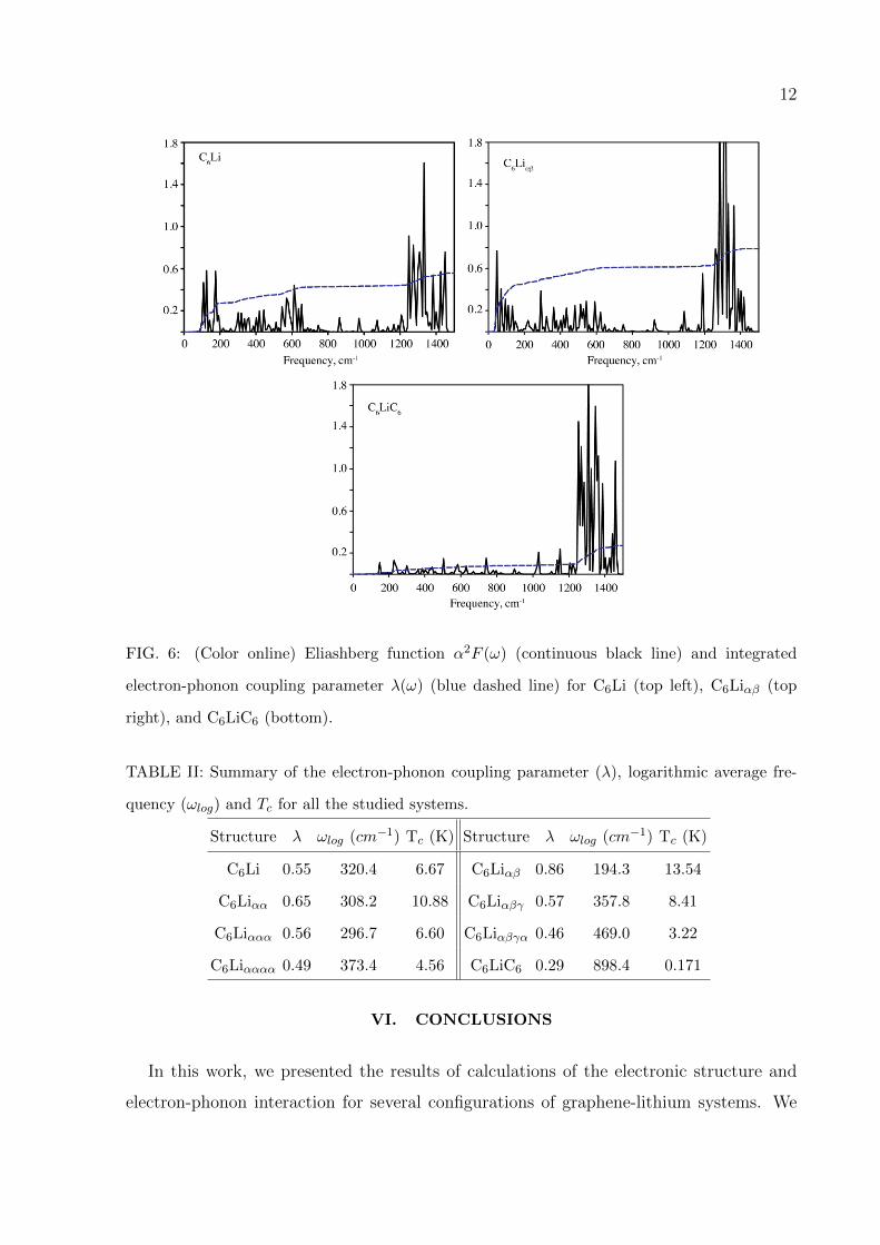
FIG. 6: (Color online) Eliashberg function α2F (ω) (continuous black line) and integrated
electron-phonon coupling parameter λ(ω) (blue dashed line) for C6Li (top left), C6Liαβ (top
right), and C6LiC6 (bottom).
TABLE II: Summary of the electron-phonon coupling parameter (λ), logarithmic average fre-
quency (ωlog) and Tc for all the studied systems.
Structure λ ωlog (cm−1) Tc (K) Structure λ ωlog (cm−1) Tc (K)
C6Li 0.55 320.4 6.67 C6Liαβ 0.86 194.3 13.54
C6Liαα 0.65 308.2 10.88 C6Liαβγ 0.57 357.8 8.41
C6Liααα 0.56 296.7 6.60 C6Liαβγα 0.46 469.0 3.22
C6Liαααα 0.49 373.4 4.56 C6LiC6 0.29 898.4 0.171
VI. CONCLUSIONS
In this work, we presented the results of calculations of the electronic structure and
electron-phonon interaction for several configurations of graphene-lithium systems. We
13
assessed the structural stability and the strength of the electron-phonon coupling with
respect to the stacking sequence and number of layers of lithium adatoms and the graphene
sheets. We found that in all studied cases, the structures were stable, but the ones that
yield the lowest energy were those where the Li adatom would sit in equivalent hollow
sites; that is, with Li stacking of the form αα, ααα, and αααα. Structural stability of the
systems was later confirmed with the calculation of the phonon dispersion curves, which
do not show the presence of any imaginary frequencies. We found that, in contrast to the
corresponding GICs, Li-covered graphene systems exhibit an incomplete charge transfer
from the lithium atoms to the graphene planes, giving rise to a lithium-derived band which
crosses the Fermi level simultaneously with graphitic π-bands. This enhances the electron-
phonon coupling strength, which was found to be highest for the structure C6Liαβ. The
calculated λ for this structure was found to be 0.86 with an average logarithmic frequency
ωlog = 194.3 cm−1 and a critical superconducting transition temperature Tc = 13.54 K.
The optimal value of TC is thus obtained for a system consisting of two graphene layers
and two lithium layers.
One of the authors (RAJ) gratefully acknowledges support by NSF under grant No.
HRD-0932421. DMG would like to thank the CSULA-MORE programs and CSU-LSAMP
fellowship for their support under grant No. HRD-1026102-518741.
[1] K. S. Novoselov, A. K. Geim, S. V. Morozov, D. Jiang, Y. Zhang, S. V. Dubonos, I. V.
Grigorieva, and A. A. Firsov, Electric Field Effect in Atomically Thin Carbon Films, Science
306, 5696 (2004).
[2] M. I. Katsnelson, K. S. Novoselov, and A. K. Geim, Chiral tunnelling and the Klein paradox
in graphene, Nature Physics 2, 620 (2006).
[3] K. S. Novoselov, Z. Jiang, Y. Zhang, S. V. Morozov, H. L. Stormer, U. Zeitler, J. C. Maan,
G. S. Boebinger, P. Kim, and A. K. Geim, Room-Temperature Quantum Hall Effect in
Graphene, Science 315, 1379 (2007).
[4] Y. Zhang, Y. W. Tan, H. L. Stormer, P. Kim, Experimental observation of the quantum
Hall effect and Berry’s phase in graphene, Nature 438, 201 (2005).
[5] R. R. Nair, P. Blake, A. N. Grigorenko, K. S. Novoselov, T. J. Booth, T. Stauber, N. M. R.
14
Peres, and A. K. Geim, Fine Structure Constant Defines Visual Transparency of Graphene,
Science 320, 1308 (2008).
[6] A.H.C. Neto, F. Guinea, N.M.R. Peres, K.S. Novoselov, and A.K. Geim, The electronic
properties of graphene, Rev. Mod. Phys. 81, 109 (2009).
[7] N. B. Hannay, T. H. Geballe, B. T. Matthias, K. Andres, P. Schmidt and D. MacNair,
Superconductivity in Graphitic Compounds, Phys. Rev. Lett. 14, 255 (1965).
[8] Y. Koike and S. Tanuma, Superconductivity in the graphite-potassium intercalation com-
pound C8K, J. Phys. Chem. Solids 41, 1111 (1980).
[9] M. Kobayashi and I. Tsujikawa, Susceptibility Fluctuation in Superconducting First Stage
Potassium Graphite Intercalation Compound near Transition Temperature, J. Phys. Soc.
Jpn. 46, 1945 (1979).
[10] M. G. Alexander, D. P. Goshorn, D. Gurard, P. Lagrange, M. El Makrini and D. G. Onn,
Superconductivity of the graphite intercalation compounds KHgC8 and RbHgC8: Evidence
from specific heat, Solid State Commun. 38, 103 (1981).
[11] Y. Iye and S. Tanuma, Superconductivity of graphite intercalation compounds with alkali-
metal amalgams, Phys. Rev. B 25, 4583 (1982).
[12] R. Al Jishi, Model for superconductivity in graphite intercalation compounds, Phys. Rev.
B 28, 112 (1983).
[13] N. Emery, C. Herold, J.-F. Mareche, and P. Lagrange, Synthesis and superconducting
properties of CaC6, Sci. Technol. Adv. Mater. 9, 044102 (2008).
[14] T. E. Weller, M. Ellerby, S. S. Saxena, R. P. Smith and N. T. Skipper, Superconductivity
in the Ytterbium Intercalated Graphite Compounds C6Yb and C6Ca, Nature Physics 1, 39
(2005).
[15] N. Emery, C. Herold, M. dAstuto, V. Garcia, Ch. Bellin, J. F. Mareche, P. Lagrange, and
G. Loupias, Superconductivity of Bulk CaC6, Physical Review Letters 95, 087003 (2005).
[16] A. C. Walters, C. A. Howard, M. H. Upton, M. P. M. Dean, A. Alatas, B. M. Leu, M.
Ellerby, D. F. McMorrow, J. P. Hill, M. Calandra, F. Mauri, Comparative study of the
phonons in non-superconducting BaC6 and superconducting CaC6 using inelastic x-ray
scattering, arXiv:1102.4767v1 [cond-mat.supr-con], (2011).
[17] R. Ricardo da Silva, J. H. S. Torres, and Y. Kopelevich, Indication of Superconductivity
at 35 K in Graphite-Sulfur Composites, Phys. Rev. Lett. 87, 147001 (2001).
15
[18] S. Moehlecke, Y. Kopelevich, and M. B. Maple, Interaction between superconducting and
ferromagnetic order parameters in graphite-sulfur composites, Phys. Rev. B 69, 134519
(2004).
[19] S. De Franceschi, L. Kouwenhoven, Ch. Schonenberger and W. Wernsdorfer, Hybrid
superconductor-quantum dot devices, Nature Nanotechnology 5, 703 (2010).
[20] M. Huefner, C. May, S. Kicin, K. Ensslin, T. Ihn, M. Hilke, K. Suter, N. F. de Rooij, and
U. Staufer, Scanning gate microscopy measurements on a superconducting single-electron
transistor, Phys. Rev. B 79, 134530 (2009).
[21] J. Delahaye, J. Hassel, R. Lindell, M. Sillanpaa, M. Paalanen, H. Seppa, and P. Hakonen,
Low-noise current amplifier based on mesoscopic Josephson junction, Science 299, 1045
(2003).
[22] B. Uchoa and A. H. Castro Neto, Superconducting States of Pure and Doped Graphene,
Phys. Rev. Lett. 98, 146801 (2007).
[23] E. Zhao and A. Paramekanti, BCS-BEC Crossover on the Two-Dimensional Honeycomb
Lattice, Phys. Rev. Lett. 97, 230404 (2006).
[24] A.M. Black-Schaffer and S. Doniach, Resonating valence bonds and mean-field d-wave su-
perconductivity in graphite, Phys. Rev. B 75, 134512 (2007).
[25] C. Honerkamp, Density Waves and Cooper Pairing on the Honeycomb Lattice, Phys. Rev.
Lett. 100, 146404 (2008).
[26] N. B. Kopnin and E. B. Sonin, BCS Superconductivity of Dirac Electrons in Graphene
Layers, Phys. Rev. Lett. 100, 246808 (2008).
[27] J. Gonzalez, Kohn-Luttinger superconductivity in graphene, Phys. Rev B 78, 205431
(2008).
[28] V. M. Loktev and V. Turkowski, Suppression of the superconducting transition temperature
of doped graphene due to thermal fluctuations of the order parameter, Phys. Rev. B 79,
233402 (2009).
[29] R. A. Jishi, M. S. Dresselhaus, and A. Chaiken, Theory of the upper critical field in graphite
intercalation compounds, Phys. Rev. B 44, 10 248 (1991).
[30] R. A. Jishi and M. S. Dresselhaus, Superconductivity in graphite intercalation compounds,
Phys. Rev. B 45, 12465 (1992).
[31] R. A. Jishi, D. M. Guzman, H. M. Alyahyaei, Theoretical Investigation of Two-Dimensional
16
Superconductivity in Intercalated Graphene Layers, Adv. Studies Theor. Phys. 5, 703
(2011).
[32] G. Profeta, M. Calandra, F. Mauri, Phonon-mediated superconductivity in graphene by
lithium deposition, Nature Physics 8, 131 (2012).
[33] K. Sugawara, K. Kanetani, T. Sato, and T. Takahashi, Fabrication of Li-intercalated bilayer
graphene, AIP Advances 1, 022103 (2011).
[34] P. Blaha, K. Schwarz, G. K. H. Madsen, D. Kavasnicka, and J. Luitz, WIEN2K: An Aug-
mented Plane Wave+Local Orbitals Program for Calculating Crystal Properties (Technische
Universitat, Wien, Austria, 2001).
http://www.wien2k.at.
[35] J. P. Perdew, K. Burke, and M. Ernzerhof, Generalized Gradient Approximation Made
Simple, Phys. Rev. Lett. 77, 2865 (1996).
[36] P. Giannozzi et al., QUANTUM ESPRESSO: a modular and open-source software project
for quantum simulations of materials, J. Phys. Condens. Matter 21, 395502 (2009).
[37] P. B. Allen and R. C. Dynes, Transition temperature of strong-coupled superconductors
reanalyzed, Phys. Rev. B 12, 905 (1975).
[38] W. L. McMillan, Transition Temperature of Strong-Coupled Superconductors, Phys. Rev.
167, 331 (1968).
[39] P. Morel and P. W. Anderson, Calculation of the Superconducting State Parameters with
Retarded Electron-Phonon Interaction, Phys. Rev. 125, 1263 (1962).
[40] R.F.W. Bader, Atoms in Molecules: A Quantum Theory (Oxford University Press, Oxford,
1990).
[41] G. Csanyi, P. B. Littlewood, Andriy H. Nevidomskyy, Chris J. Pickard, and B. D. Simons,
The role of the interlayer state in the electronic structure of superconducting graphite
intercalated compounds, Nature Physics 1, 42 (2005).
[42] M. Calandra and F. Mauri, Theoretical Explanation of Superconductivity in C6Ca, Phys.
Rev. Lett. 95, 237002 (2005).
[43] M.S. Dresselhaus and G. Dresselhaus, Intercalation Compounds of Graphite, Adv. Phys.
51, 1 (2002).