superflo technical brochure (oct 11)
TRANSCRIPT
Technical Data and Dimensions
chilled and cold water pipework
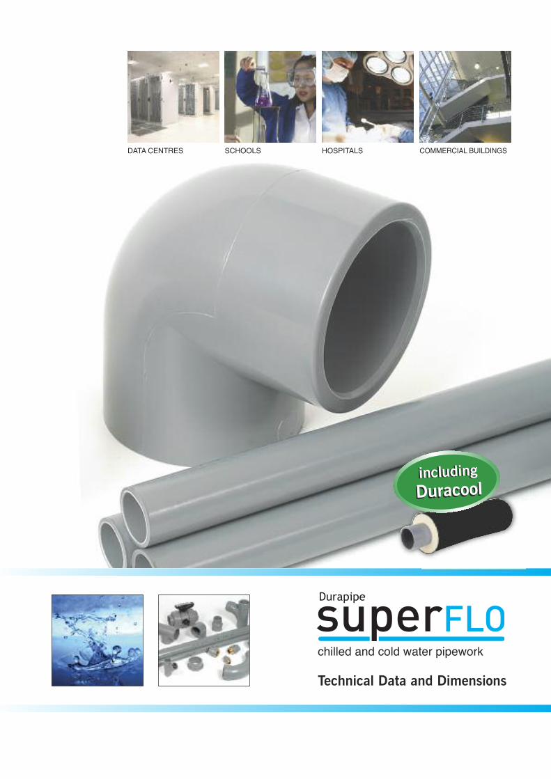
COMMERCIAL BUILDINGSDATA CENTRES SCHOOLS HOSPITALS
including
DuracoolincludingDuracool
CHILLED AND BOOSTED COLD WATER
SuperFLO
Durapipe SuperFLO offers tremendous advantages for chilled water/air conditioning or boosted cold water services in buildings.
When considering environmental control systems, or more specifically, the pipework
requirements for chilled or boosted cold water applications, Durapipe SuperFLO
provides the perfect solution.
Durapipe SuperFLO is lightweight and remains extremely tough and durable even
at temperatures as low as -40ºC.
The complete system, which incorporates pipes, fittings and valves, offers a 50-year
design life as well as numerous benefits that alternative pipework materials cannot
provide. These include reduced installation costs via a fast solvent-weld
jointing procedure, low maintenance costs due to its limescale and corrosion
resistance properties as well as being extremely lightweight making the product
much easier to handle on site.
Durapipe SuperFLO is available in sizes ranging from 16mm to 315mm.
Key Product Information
• Size Range: 16mm to 315mm
• Pressure Rating: PN10 - 16mm to 250mm, PN8 - 315mm
• Temperature Rating: -40°C to 70°C
Typical Applications
All building types for:
• Chilled water/air conditioning
• Boosted cold water
Key Product Features
• Lightweight
• Corrosion and limescale resistant
• Impact resistant
• Fast, simple jointing
• Ductile down to -40°C
• Reduced installation costs
• 50-year design life
• WRAS approved
chilled and cold water pipework
email: [email protected] web: www.durapipe.co.uk 3
Contents
page page
AccessoriesCobra pipe clips...............................................................21Rubber lined pipe clips .....................................................22Pipe trays........................................................................22Chamfering and de-burring tools ........................................22Pipe cutters.....................................................................22SuperFLO one-step solvent cement and eco cleaner .............22
System Design and Installation GuidePressure/temperature relationship ....................................23Flow calculations/Flow nomogram ..............................23-24Thermal expansion and contraction .............................25-26Jointing guide ...........................................................27-28Design of pipe supports and clips.....................................29Flexible hoses and metal threaded fittings .........................30Bushes, reducers, threaded adaptors and flanges..........31-32Flanged joints ................................................................32
Additional Important Information.................................33-35
Duracool Overview ..........................................................36Duracool system overview.................................................37Technical considerations when installing Duracool ...............38Sealants for use with Duracool ..........................................38Installation of Thermo-Click shells......................................39Duracool pipe preparation............................................40-41Data sheet Thermo-Click insulation shells...........................42Duracool product range ...............................................43-45
Durapipe UK Pipework Systems .......................................46
Conditions of Sale ...........................................................47
Durapipe SuperFLO Overview.............................................2
SuperFLO Introduction ...................................................4-5SuperFLO Valves and Flow Control .....................................6SuperFLO Case Study Examples .........................................7
SuperFLO Pipes and Fittings RangeMetric pipe system.............................................................8Sockets.............................................................................8Reducing bushes ...............................................................9Reducers ..........................................................................9Elbows 45° .....................................................................10Elbows 90° .....................................................................10Tees 45° .......................................................................10Tees 90° .......................................................................11Bends 90°.....................................................................12Fabricated bends 90°......................................................12Caps.............................................................................12Socket unions ................................................................13Male threaded adaptors ..................................................13Female threaded adaptors ...............................................13Hose adaptors ...............................................................14Male composite unions ...................................................14Female composite unions................................................14ABS/male brass threaded fittings......................................15ABS/female brass threaded fittings ...................................15ABS flexible braided hoses ..............................................15Wall brackets.................................................................16Stub flanges ..................................................................16Blank flanges.................................................................16Backing rings.................................................................17Flat gaskets/stub flanges .................................................18Flange assembly kits ......................................................18Valve support plates .......................................................18
ValvesVKD Double union ball valves............................................19VXE Double union ball valves ............................................19UC Ball check valves........................................................19UA Air release valves........................................................20RV Y-Type strainers ..........................................................20PR Pressure release valves ................................................20FK Butterfly valves ...........................................................21
Tel: +44 (0)1543 279909 Fax: +44 (0)1543 2794504
Copper pipe vs ABS pipe Steel vs ABS
Corroded steel pipe Plastic pipe
Reduced Installation CostsDue to the many factors that make DurapipeSuperFLO easier to install on site, DurapipeSuperFLO can deliver installed cost savingswhen compared to a traditional welded orthreaded metal pipe system. This is recognisedby an independent BSRIA report.
Corrosion and Limescale ResistantBoth limescale and corrosion can become a problematic feature of any metal-based pipeworksystem. However, the smooth bore lining of Durapipe SuperFLO pipework prohibits anylimescale build-up throughout the life of the system, maintaining consistent flow rates.
Superior FlowLow fluid friction allows higher flowvelocities than metal pipes and also inhibitsthe formation of scale, with consequentsavings in pump energy consumption, and reduced pressure drops.
Solvent welding is a simple process which produces a permanent joint of strengthequal to, or exceeding, the pipe itself. No special tools, equipment or hot works
permits are required.
• No electricity required• No flame or combustible gas bottles
required on-site• No site downtime due to electricity
shut down• No hot works permits or need for site
segregation
Fast, Simple and High Integrity Jointing
LightweightDurapipe SuperFLOis approximatelyone-sixth of theweight of steelpipework.
Therefore, DurapipeSuperFLO is mucheasier to handle,especially duringinstallation on-site.
The energy used to make Durapipe SuperFLO from raw material compares favourably with, for example, steel pipe manufacturebecause lower conversion temperatures are needed. Furthermore, our processes are clean with low process emissions.
Durapipe SuperFLO pipe and fittings are cheaper and easier to transport because they are lighter in weight than the equivalentmetal products. They can be recycled into other products at the end of their life, and scrap during the manufacturing process canalso be recycled and reused. This minimises the need for any thermoplastic pipe scrap entering the waste stream.
Sustainability and Environment
Tough and DurableThe Butadiene element of ABSaffords exceptional resistanceto accidental damage, even atsub-zero temperatures.Durapipe SuperFLO is therefore extremely ductileand performs at temperaturesas low as minus 40ºC.
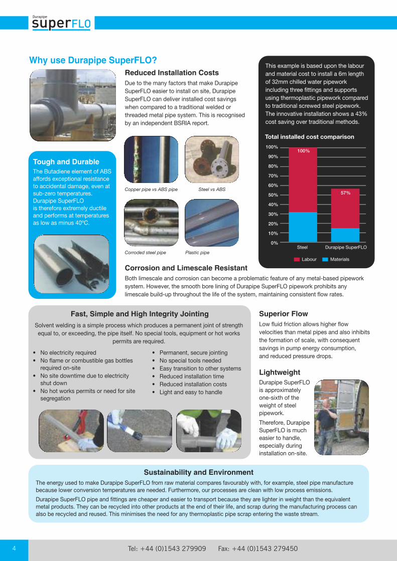
Why use Durapipe SuperFLO?This example is based upon the labourand material cost to install a 6m lengthof 32mm chilled water pipeworkincluding three fittings and supportsusing thermoplastic pipework comparedto traditional screwed steel pipework.The innovative installation shows a 43%cost saving over traditional methods.
100%
90%
80%
70%
60%
50%
40%
30%
20%
10%
0%
Total installed cost comparison
Durapipe SuperFLO
Labour Materials
• Permanent, secure jointing• No special tools needed• Easy transition to other systems• Reduced installation time• Reduced installation costs• Light and easy to handle
Steel
100%
57%
email: [email protected] web: www.durapipe.co.uk 5
SuperFLO Introduction
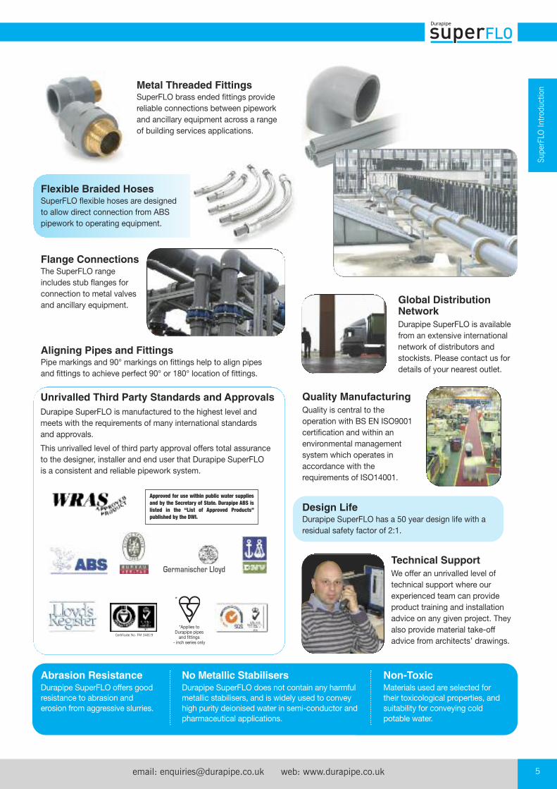
Quality ManufacturingQuality is central to theoperation with BS EN ISO9001certification and within anenvironmental managementsystem which operates inaccordance with therequirements of ISO14001.
Abrasion ResistanceDurapipe SuperFLO offers goodresistance to abrasion anderosion from aggressive slurries.
No Metallic StabilisersDurapipe SuperFLO does not contain any harmfulmetallic stabilisers, and is widely used to conveyhigh purity deionised water in semi-conductor andpharmaceutical applications.
Non-ToxicMaterials used are selected fortheir toxicological properties, andsuitability for conveying coldpotable water.
Technical SupportWe offer an unrivalled level oftechnical support where ourexperienced team can provideproduct training and installationadvice on any given project. Theyalso provide material take-offadvice from architects’ drawings.
Unrivalled Third Party Standards and ApprovalsDurapipe SuperFLO is manufactured to the highest level andmeets with the requirements of many international standards and approvals.
This unrivalled level of third party approval offers total assuranceto the designer, installer and end user that Durapipe SuperFLO is a consistent and reliable pipework system.
Metal Threaded FittingsSuperFLO brass ended fittings providereliable connections between pipeworkand ancillary equipment across a rangeof building services applications.
Flexible Braided HosesSuperFLO flexible hoses are designedto allow direct connection from ABSpipework to operating equipment.
Approved for use within public water supplies
and by the Secretary of State. Durapipe ABS is
listed in the “List of Approved Products”
published by the DWI.
*Applies toDurapipe pipesand fittings
- inch series only
*
Certificate No. FM 34819
Germanischer Lloyd
Global DistributionNetworkDurapipe SuperFLO is availablefrom an extensive internationalnetwork of distributors andstockists. Please contact us fordetails of your nearest outlet.
Aligning Pipes and FittingsPipe markings and 90° markings on fittings help to align pipesand fittings to achieve perfect 90° or 180° location of fittings.
Design LifeDurapipe SuperFLO has a 50 year design life with aresidual safety factor of 2:1.
Flange ConnectionsThe SuperFLO rangeincludes stub flanges forconnection to metal valvesand ancillary equipment.

Tel: +44 (0)1543 279909 Fax: +44 (0)1543 2794506
Industry AffiliationsWe are members of a number of independent industry affiliation bodies and support various specific building servicesrelated organisations.
Market Sector ApplicationsDurapipe SuperFLO has been used for boosted cold water and chilled water/air conditioning applications, within theBuilding Services sector for many years. The system is commonly installed to provide pipework benefits for:
A comprehensive range of valves is available to support theSuperFLO system, including the new VXE Easyfit ball valve.
Easyfit is an innovative double union ball valve introducing anadvanced method of installation for a long-term, trouble-freeservice, along with a level of customisation never before seenin a plastic valve.
For further information contact our specialist Valve Department on 01543 272424.
Valves and Flow Control
One of the many benefits of using SuperFLO pipework instead of traditional materials is the simplicity of the jointing process when using plastic.
Furthermore, our team can advise pipework installers on methods of best practice when jointing plasticpiping. We offer FREE practical product jointing advice on our SuperFLO range including jointingdemonstrations, installation advice and even materialand product selection.
This can be done either on site as part of our on-sitesupport service or even at our UK office.
FREE Practical Jointing Advice
Schools
Hospitals
Offices
Data Centres
Public Buildings
email: [email protected] web: www.durapipe.co.uk 7
SuperFLO Introduction
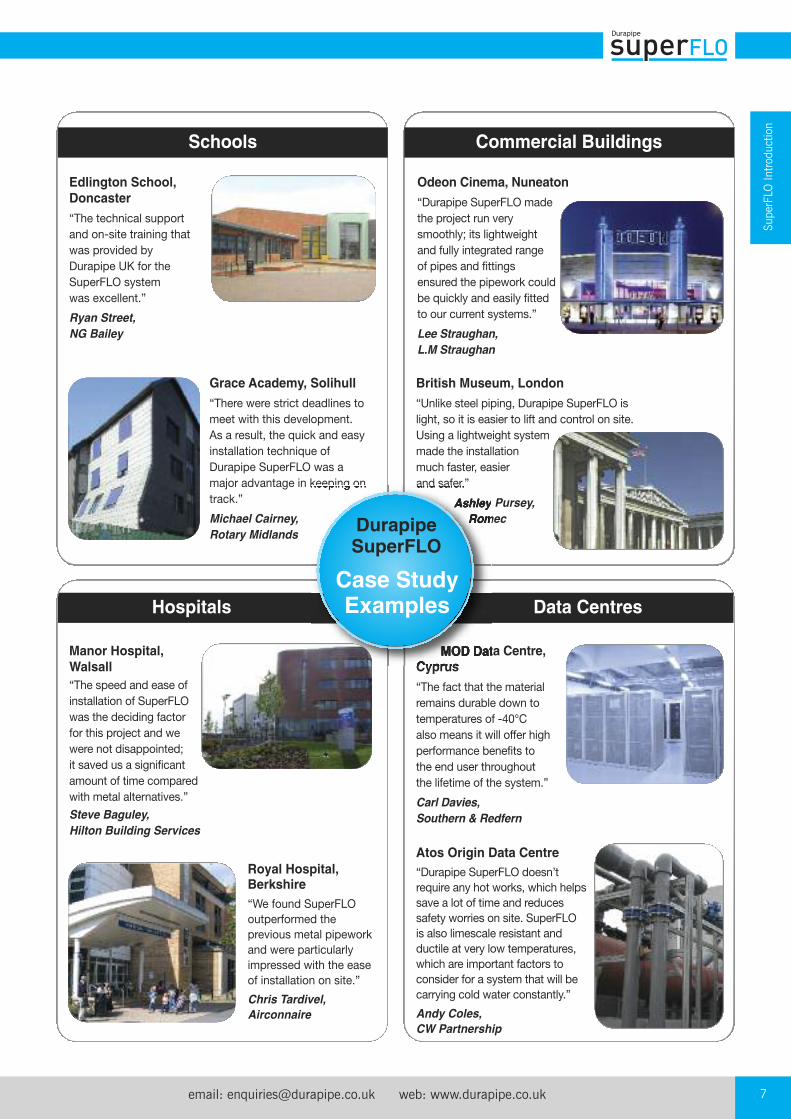
Edlington School,Doncaster“The technical support and on-site training thatwas provided by Durapipe UK for theSuperFLO system was excellent.”
Ryan Street,
NG Bailey
Grace Academy, Solihull“There were strict deadlines tomeet with this development. As a result, the quick and easyinstallation technique ofDurapipe SuperFLO was amajor advantage in keeping ontrack.”
Michael Cairney,
Rotary Midlands
Odeon Cinema, Nuneaton“Durapipe SuperFLO madethe project run verysmoothly; its lightweightand fully integrated range of pipes and fittingsensured the pipework couldbe quickly and easily fittedto our current systems.”
Lee Straughan,
L.M Straughan
British Museum, London“Unlike steel piping, Durapipe SuperFLO is light, so it is easier to lift and control on site. Using a lightweight systemmade the installationmuch faster, easier and safer.”
Ashley Pursey,
Romec
MOD Data Centre,Cyprus“The fact that the materialremains durable down totemperatures of -40°C also means it will offer highperformance benefits to the end user throughout the lifetime of the system.”
Carl Davies,
Southern & Redfern
Atos Origin Data Centre“Durapipe SuperFLO doesn’trequire any hot works, which helpssave a lot of time and reducessafety worries on site. SuperFLO is also limescale resistant andductile at very low temperatures,which are important factors toconsider for a system that will becarrying cold water constantly.”
Andy Coles,
CW Partnership
Manor Hospital, Walsall“The speed and ease ofinstallation of SuperFLOwas the deciding factorfor this project and wewere not disappointed; it saved us a significantamount of time comparedwith metal alternatives.”
Steve Baguley,
Hilton Building Services
Royal Hospital,Berkshire“We found SuperFLOoutperformed theprevious metal pipeworkand were particularlyimpressed with the easeof installation on site.”
Chris Tardivel,
Airconnaire
Commercial BuildingsSchools
Hospitals
DurapipeSuperFLO
Case StudyExamples Data Centres
Tel: +44 (0)1543 279909 Fax: +44 (0)1543 2794508
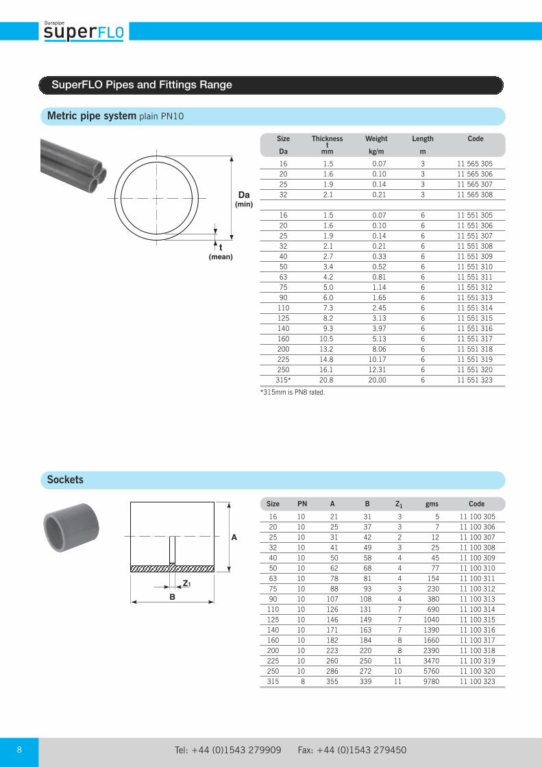
Metric pipe system plain PN10
Size Thickness Weight Length Code t Da mm kg/m m
16 1.5 0.07 3 11 565 305 20 1.6 0.10 3 11 565 306 25 1.9 0.14 3 11 565 307 32 2.1 0.21 3 11 565 308
16 1.5 0.07 6 11 551 305 20 1.6 0.10 6 11 551 306 25 1.9 0.14 6 11 551 307 32 2.1 0.21 6 11 551 308 40 2.7 0.33 6 11 551 309 50 3.4 0.52 6 11 551 310 63 4.2 0.81 6 11 551 311 75 5.0 1.14 6 11 551 312 90 6.0 1.65 6 11 551 313 110 7.3 2.45 6 11 551 314 125 8.2 3.13 6 11 551 315 140 9.3 3.97 6 11 551 316 160 10.5 5.13 6 11 551 317 200 13.2 8.06 6 11 551 318 225 14.8 10.17 6 11 551 319 250 16.1 12.31 6 11 551 320 315* 20.8 20.00 6 11 551 323
*315mm is PN8 rated.
Da (min)
t (mean)
Sockets
Size PN A B Z1 gms Code
16 10 21 31 3 5 11 100 305 20 10 25 37 3 7 11 100 306 25 10 31 42 2 12 11 100 307 32 10 41 49 3 25 11 100 308 40 10 50 58 4 45 11 100 309 50 10 62 68 4 77 11 100 310 63 10 78 81 4 154 11 100 311 75 10 88 93 3 230 11 100 312 90 10 107 108 4 380 11 100 313 110 10 126 131 7 690 11 100 314 125 10 146 149 7 1040 11 100 315 140 10 171 163 7 1390 11 100 316 160 10 182 184 8 1660 11 100 317 200 10 223 220 8 2390 11 100 318 225 10 260 250 11 3470 11 100 319 250 10 286 272 10 5760 11 100 320 315 8 355 339 11 9780 11 100 323
B
Z1
A
SuperFLO Pipes and Fittings Range
email: [email protected] web: www.durapipe.co.uk 9
SuperFLO Pipes
and Fittings Range
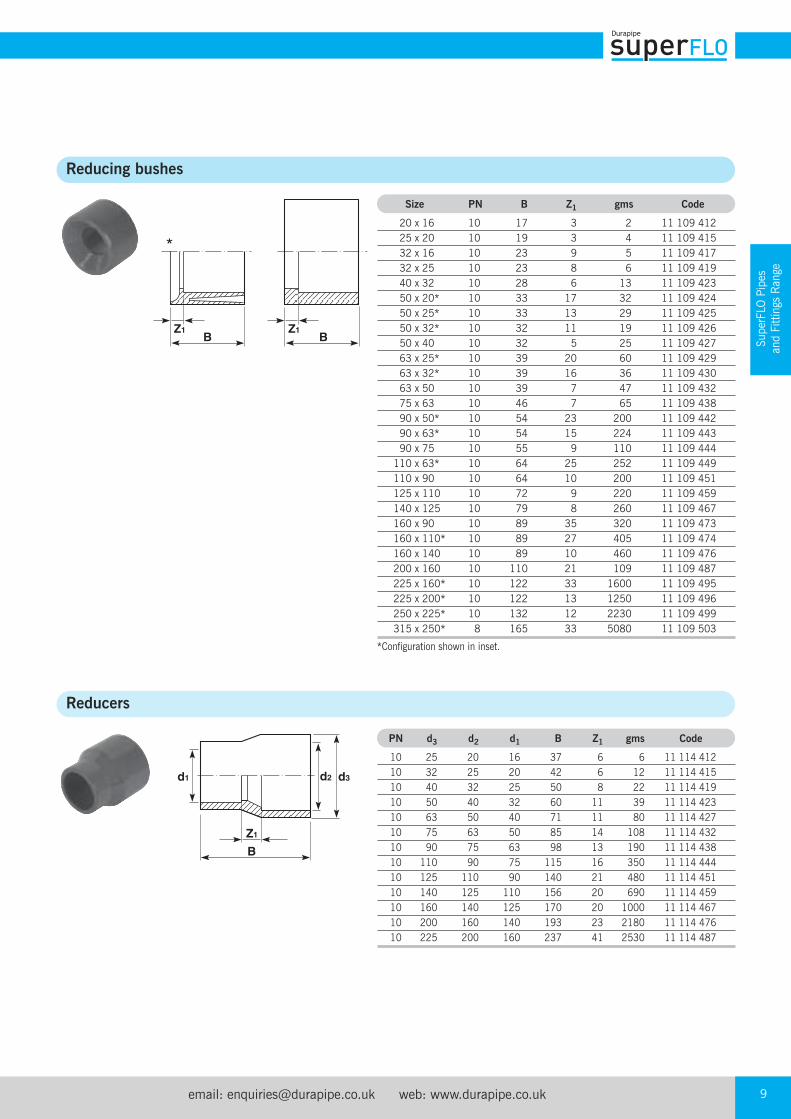
Reducing bushes
Reducers
BZ1
BZ1
Size PN B Z1 gms Code
20 x 16 10 17 3 2 11 109 412 25 x 20 10 19 3 4 11 109 415 32 x 16 10 23 9 5 11 109 417 32 x 25 10 23 8 6 11 109 419 40 x 32 10 28 6 13 11 109 423 50 x 20* 10 33 17 32 11 109 424 50 x 25* 10 33 13 29 11 109 425 50 x 32* 10 32 11 19 11 109 426 50 x 40 10 32 5 25 11 109 427 63 x 25* 10 39 20 60 11 109 429 63 x 32* 10 39 16 36 11 109 430 63 x 50 10 39 7 47 11 109 432 75 x 63 10 46 7 65 11 109 438 90 x 50* 10 54 23 200 11 109 442 90 x 63* 10 54 15 224 11 109 443 90 x 75 10 55 9 110 11 109 444 110 x 63* 10 64 25 252 11 109 449 110 x 90 10 64 10 200 11 109 451 125 x 110 10 72 9 220 11 109 459 140 x 125 10 79 8 260 11 109 467 160 x 90 10 89 35 320 11 109 473 160 x 110* 10 89 27 405 11 109 474 160 x 140 10 89 10 460 11 109 476 200 x 160 10 110 21 109 11 109 487 225 x 160* 10 122 33 1600 11 109 495 225 x 200* 10 122 13 1250 11 109 496 250 x 225* 10 132 12 2230 11 109 499 315 x 250* 8 165 33 5080 11 109 503
*Configuration shown in inset.
B
d3
Z1
d1 d2
PN d3 d2 d1 B Z1 gms Code
10 25 20 16 37 6 6 11 114 412 10 32 25 20 42 6 12 11 114 415 10 40 32 25 50 8 22 11 114 419 10 50 40 32 60 11 39 11 114 423 10 63 50 40 71 11 80 11 114 427 10 75 63 50 85 14 108 11 114 432 10 90 75 63 98 13 190 11 114 438 10 110 90 75 115 16 350 11 114 444 10 125 110 90 140 21 480 11 114 451 10 140 125 110 156 20 690 11 114 459 10 160 140 125 170 20 1000 11 114 467 10 200 160 140 193 23 2180 11 114 476 10 225 200 160 237 41 2530 11 114 487
*
Tel: +44 (0)1543 279909 Fax: +44 (0)1543 27945010
Elbows 45°
Size PN A C Z1 gms Code
16 10 21 20 5 5 11 119 305 20 10 25 22 5 7 11 119 306 25 10 31 26 7 14 11 119 307 32 10 40 31 8 27 11 119 308 40 10 50 37 10 54 11 119 309 50 10 62 45 13 100 11 119 310 63 10 82 54 16 180 11 119 311 75 10 90 63 17 300 11 119 312 90 10 112 70 18 550 11 119 313 110 10 137 90 27 950 11 119 314 125 10 155 103 31 1350 11 119 315 140 10 173 115 37 1980 11 119 316 160 10 190 125 35 2920 11 119 317 200 10 230 152 44 3460 11 119 318 225 10 260 174 51 4920 11 119 319 250 10 286 189 58 5900 11 119 320 315 8 359 230 66 11880 11 119 323
Elbows 90°
Size PN A C Z1 gms Code
16 10 20 24 10 6 11 115 305 20 10 25 28 11 10 11 115 306 25 10 31 34 15 17 11 115 307 32 10 40 41 18 35 11 115 308 40 10 50 47 20 68 11 115 309 50 10 62 59 26 129 11 115 310 63 10 78 71 31 230 11 115 311 75 10 90 83 38 385 11 115 312 90 10 112 100 49 690 11 115 313 110 10 136 125 63 1220 11 115 314 125 10 155 140 63 1720 11 115 315 140 10 173 153 76 2390 11 115 316 160 10 190 172 79 3600 11 115 317 200 10 235 207 110 4300 11 115 318 225 10 260 240 119 6550 11 115 319 250 10 286 319 188 9560 11 115 320 315 8 359 400 236 17910 11 115 323
Z1
A
C
A
Z1
C
Tees 45° plain
Size PN A B C Z1 Z2 Z3 gms Code
20 10 28 68 43 6 26 34 30 11 418 306 25 10 33 81 52 7 29 55 45 11 418 307 32 10 41 98 65 9 42 52 80 11 418 308 40 10 50 117 77 11 51 65 135 11 418 309 50 10 60 140 95 12 63 78 195 11 418 310 63 10 74 169 114 13 76 93 410 11 418 311
B
A
Z3
Z1
C
Z2
email: [email protected] web: www.durapipe.co.uk 11
SuperFLO Pipes
and Fittings Range
Tees 90° equal
Size PN A B C Z1 gms Code
16 10 21 47 25 10 7 11 122 305 20 10 25 57 30 12 12 11 122 306 25 10 31 67 34 15 24 11 122 307 32 10 40 81 43 18 48 11 122 308 40 10 50 99 50 23 87 11 122 309 50 10 62 119 62 28 160 11 122 310 63 10 78 146 70 34 300 11 122 311 75 10 90 172 87 36 510 11 122 312 90 10 112 205 104 46 900 11 122 313 110 10 132 248 128 60 1650 11 122 314 125 10 154 276 143 67 2300 11 122 315 140 10 172 307 153 72 3200 11 122 316 160 10 190 343 172 87 4800 11 122 317 200 10 237 413 206 101 5800 11 122 318 225 10 262 482 239 120 7700 11 122 319 250 10 286 518 259 128 10160 11 122 320 315 8 360 652 326 162 19390 11 122 323
Tees 90° swept
Size PN A B C D Z1 Z2 Z3 gms Code
32 10 41 115 79 79 57 57 14 90 11 148 308 50 10 62 160 105 105 74 74 24 259 11 148 310 63 10 78 195 125 125 87 87 32 480 11 148 311 75 10 92 210 125 125 81 81 41 601 11 148 312 110 10 139 315 190 190 127 127 62 2235 11 148 314
C
Z1
BAZ1
C
Z1
D
A
Z3
Z2B
Tees 90° reducing
Size PN A B C D Z1 gms Code
25 x 20 10 31 67 31 25 14 22 11 124 415 32 x 20 10 40 81 35 25 18 40 11 124 418 32 x 25 10 40 81 37 31 18 41 11 124 419 40 x 20 10 50 98 39 25 22 72 11 124 421 40 x 25 10 50 98 41 31 22 72 11 124 422 50 x 20 10 62 119 44 29 27 104 11 124 424 50 x 25 10 62 119 46 31 27 140 11 124 425 50 x 32 10 62 119 50 40 27 140 11 124 426 63 x 25 10 78 146 53 31 34 250 11 124 429 63 x 32 10 78 146 57 40 34 250 11 124 430 75 x 32 10 91 168 62 41 40 391 11 124 435 75 x 40 10 91 168 66 50 40 398 11 124 436 75 x 50 10 91 168 71 61 40 406 11 124 437 75 x 63 10 91 168 78 76 40 428 11 124 438 90 x 40 10 109 198 74 50 48 642 11 124 441 90 x 50 10 109 198 79 61 48 649 11 124 442 90 x 63 10 109 198 86 76 48 664 11 124 443 90 x 75 10 109 198 92 91 48 693 11 124 444 110 x 50 10 133 244 92 61 61 1165 11 124 448 110 x 63 10 133 244 99 76 61 1173 11 124 449 110 x 75 10 133 244 105 91 61 1188 11 124 450 110 x 90 10 133 244 112 109 61 1210 11 124 451
A
D
Z1
C
Z1B
Tel: +44 (0)1543 279909 Fax: +44 (0)1543 27945012
Bends 90°
Z1
C
A
Size PN A C Z1 Weight Code gms
20 10 26 57 40 18 11 118 306 25 10 33 69 50 38 11 118 307 32 10 41 87 64 75 11 118 308 40 10 51 107 80 135 11 118 309 50 10 62 132 100 245 11 118 310 63 10 78 165 126 470 11 118 311 75 10 93 195 150 810 11 118 312 90 10 111 234 180 1350 11 118 313 110 10 140 284 220 2570 11 118 314
Fabricated bends 90° plain
Caps plain
CR
E
Size C E R Weight Code gms
125 750 250 500 4790 11 309 315 140 840 280 560 6700 11 309 316 160 960 320 640 10040 11 309 317 200 1200 400 800 19480 11 309 318 225 1350 450 900 27850 11 309 319
B
A
Size PN A B Weight Code gms
16 10 21 16 3 11 149 305 20 10 25 21 5 11 149 306 25 10 31 24 8 11 149 307 32 10 41 30 19 11 149 308 40 10 50 35 30 11 149 309 50 10 62 41 53 11 149 310 63 10 78 50 106 11 149 311 75 10 94 59 180 11 149 312 90 10 112 70 300 11 149 313 110 10 136 84 570 11 149 314
email: [email protected] web: www.durapipe.co.uk 13
SuperFLO Pipes
and Fittings Range
Socket unions
Size PN A B Z1 Z2 Weight Code gms
16 10 34 42 3 10 19 11 205 305 20 10 40 47 3 10 29 11 205 306 25 10 50 53 3 10 46 11 205 307 32 10 57 64 8 11 70 11 205 308 40 10 73 78 10 13 140 11 205 309 50 10 80 92 13 15 154 11 205 310 63 10 102 111 14 20 270 11 205 311 75 10 135 107 8 13 720 11 205 312 90 10 157 115 7 4 750 11 205 313 110 10 183 138 8 7 1115 11 205 314
EPDM seal as standard.
B
Z2Z1
A
Male threaded adaptors BSP taper male thread
Size PN T* A B D Z1 Weight Code d2 d1 gms
16- 12- 10 3⁄8 19 35 11 22 7 11 151 331 20- 16- 10 3⁄8 24 38 12 24 7 11 151 332 20- 16- 10 1⁄2 24 42 15 28 7 11 151 333 20- 16- 10 3⁄4 30 46 16 28 8 11 151 327 25- 20- 10 1⁄2 30 46 15 28 13 11 151 334 25- 20- 10 3⁄4 30 48 16 31 14 11 151 335 32- 25- 10 1⁄2 36 51 15 32 23 11 151 352 32- 25- 10 3⁄4 36 52 16 33 23 11 151 336 32- 25- 10 1 36 55 19 36 23 11 151 337 40- 32- 10 1 46 58 20 36 36 11 151 338 40- 32- 10 11⁄4 46 60 21 37 38 11 151 339 50- 40- 10 11⁄4 55 66 22 39 70 11 151 340 50- 40- 10 11⁄2 55 66 21 39 70 11 151 341 63- 50- 10 11⁄2 72 73 22 41 115 11 151 342 63- 50- 10 2 72 78 26 46 123 11 151 343 75- 63- 10 2 80 84 26 46 150 11 151 345
*Thread size designation.
Size PN T* A B Z1 Z2 Weight Code d2 d1 gms
16- 12- 10 3⁄8 24 28 11 16 7 11 153 331 20- 16- 10 1⁄2 30 35 15 21 14 11 153 333 25- 20- 10 3⁄4 38 39 16 22 21 11 153 335 32- 25- 10 1 45 45 18 26 42 11 153 337 40- 32- 10 11⁄4 56 54 21 31 69 11 153 339 50- 40- 10 11⁄2 64 60 21 33 108 11 153 341 63- 50- 10 2 78 72 25 41 169 11 153 343
*Thread size designation.
Female threaded adaptors BSP taper female threaded reinforced
B
Z1
D
A(A/F)d2 d1
Z1
Z2
B
d1 d2 AT
Tel: +44 (0)1543 279909 Fax: +44 (0)1543 27945014
Female composite unions ABS/Brass, BSP parallel female
Male composite unions ABS/Brass, BSP taper male thread
Size PN A B Z1 Z2 Weight Code gms
16 x 3⁄8* 10 32 37 3 7 105 11 216 305 20 x 1⁄2* 10 40 43 3 7 175 11 216 306 25 x 3⁄4* 10 48 47 3 7 320 11 216 307 32 x 1* 10 55 59 8 9 420 11 216 308 40 x 11⁄4* 10 65 68 10 8 620 11 216 309 50 x 11⁄2* 10 78 76 12 9 1000 11 216 310 63 x 2* 10 88 89 12 11 1200 11 216 311
*Thread sizes designation.Fitted with brass retaining nut and EPDM rubber seal.Brass material to BS 2872, WRAS approved.
Size PN A B Z1 Z2 Weight Code gms
16 x 3⁄8* 10 32 48 3 9 100 11 217 305 20 x 1⁄2* 10 40 54 3 9 165 11 217 306 25 x 3⁄4* 10 48 74 3 10 250 11 217 307 32 x 1* 10 55 86 8 11 310 11 217 308
40 x 11⁄4* 10 65 94 10 11 450 11 217 309 50 x 11⁄2* 10 78 108 12 12 800 11 217 310 63 x 2* 10 88 126 12 14 950 11 217 311
*Thread sizes designation.Fitted with brass retaining nut and EPDM rubber seal.Brass material to BS 2872, WRAS approved.
Z1
A(A/F)
B
Z2
B
Z1
A(A/F)
Hose adaptors spigot end
D
B
Size PN B D Weight Code gms
16 10 60 25 8 11 158 305 20 10 75 30 13 11 158 306 25 10 80 35 20 11 158 307 32 10 90 40 32 11 158 308

email: [email protected] web: www.durapipe.co.uk 15
SuperFLO Pipes
and Fittings Range
Size Description Code
20 ABS Flexible hose 300mm long x 20 x 1⁄2" 11 450 306
25 ABS Flexible hose 300mm long x 25 x 3⁄4" 11 450 307
32 ABS Flexible hose 300mm long x 32 x 1" 11 450 308
20 ABS Flexible hose 600mm long x 20 x 1⁄2" 11 451 306
25 ABS Flexible hose 600mm long x 25 x 3⁄4" 11 451 307
32 ABS Flexible hose 600mm long x 32 x 1" 11 451 308
ABS flexible braided hoses plain spigot x BSP
Size PN D D1 L Z SW Code
20 x 1⁄2 10 35 29 55 40 36 11 228 306 25 x 3⁄4 10 43 34 58 42 44 11 228 307 32 x 1 10 50 43 66 48 51 11 228 308 40 x 11⁄4 10 62 52 74 53 63 11 228 309
ABS/male brass threaded fittings BSP
Size PN D D1 L Z SW Code
20 x 1⁄2 10 35 29 40 11 36 11 229 306 25 x 3⁄4 10 43 34 42 11 44 11 229 307 32 x 1 10 50 43 48 12 51 11 229 308
40 x 11⁄4 10 62 55 54 13 63 11 229 309
ABS/female brass threaded fittings BSP
SW
ZI
D1 R Dd
SW
ZI
D1 Rpd D
Tel: +44 (0)1543 279909 Fax: +44 (0)1543 27945016
Wall brackets ABS/brass body
BA
Z2
Z1 C
D
Size PN A B C D Z1 Z2 Weight Code gms
16 - 3⁄8* 10 15 4.5 6 19 17 9 180 31 422 326 20 - 1⁄2* 10 16.5 4.5 6 19 18 9 185 31 422 327 25 - 1⁄2* 10 20 4.5 5 24 19 11 215 31 422 328 25 - 3⁄4* 10 20 4.5 5 24 19 11 200 31 422 329
*Thread sizes designation.
Stub flanges serrated face
B
D
Z1
A
Size PN A B D Z1 Weight Code gms
16 10 29 17 6 3 5 11 135 305 20 10 34 20 6 3 8 11 135 306 25 10 41 22 7 3 13 11 135 307 32 10 50 26 7 3 19 11 135 308 40 10 61 30 8 3 36 11 135 309 50 10 73 35 8 3 60 11 135 310 63 10 90 42 9 4 100 11 135 311 75 10 106 49 10 4 150 11 135 312 90 10 125 59 11 6 240 11 135 313 110 10 149 68 12 6 370 11 135 314 125 10 165 76 13 5 520 11 135 315 140 10 180 83 14 7 680 11 135 316 160 10 205 93 16 5 930 11 135 317 200* 10 252 114 17 6 1520 11 135 318 225 10 273 126 24 6 1360 11 135 319 250 10 306 140 20 9 2140 11 135 320 315 10 375 180 32 14 5000 11 135 323
*The 200mm (NW175) stub flange supplied by Durapipe when used in conjunctionwith backing ring; code number 421 318 and 420 318 has a bolt circle diameterwhich matches 225mm (NW200) valves and fittings (295mm).
Note: 125mm and 200mm stub flanges are not suitable for connection to DN125 andDN200 butterfly valves.
Size PN A B K L No. Weight Code holes gms
32 10 116 13 85 14 4 139 11 323 308 40 10 141 13 100 18 4 204 11 323 309 50 10 153 13 110 18.5 4 237 11 323 310 63 10 166 19 124 18 4 447 11 323 311 75 10 186 19 145 18.5 4 568 11 323 312 90 10 201 19 159 18 8 645 11 323 313 110 10 221 26 180 18 8 715 11 323 314 125 10 251 26 210 18 8 1338 11 323 315 140 10 251 26 210 18 8 1338 11 323 316 160 10 286 27 240 23 8 1720 11 323 317
Note: Durapipe backing rings must be used in conjunction with blank flanges.
DIN 2501 16 bar/PN16
Blank flanges
B
AK
L
email: [email protected] web: www.durapipe.co.uk 17
SuperFLO Pipes
and Fittings Range
Backing rings galvanised mild steel
Size A B C P L No. Weight Code holes gms
16 90 7 23 61 14 4 240 13 421 305
20 96 6 28 65 14 4 300 13 421 306
25 106 7 34 75 14 4 320 13 421 307
32 116 7 42 85 14 4 350 13 421 308
40 142 7 51 100 18 4 420 13 421 309
50 152 7 62 110 18 4 710 13 421 310
63 165 8 78 125 18 4 1010 13 421 311
75 186 9 92 145 18 4 1280 13 421 312
90 201 9 110 160 18 8 1380 13 421 313
110 220 9 133 180 18 8 1430 13 421 314
125 253 8 150 210 18 8 1960 13 421 315
140 251 11 167 210 18 8 2060 13 421 316
160 286 11 190 240 22 8 2700 13 421 317
Drilled to DIN 2501 (BS4504) PN10/PN16
Size A B C P L No. Weight Code holes gms
200 340 11 235 295 22 8 3830 13 421 318 225 340 11 249 295 22 8 3190 13 421 319 250 396 20 278 350 22 12 9450 13 421 320 315 448 20 349 402 22 12 8400 13 421 323
Drilled to DIN 2501 (BS4504) PN10
Size A B C P L No. Weight Code holes gms
200 340 11 235 295 22 12 3830 13 420 318 225 340 11 249 295 22 12 3190 13 420 319 250 405 20 278 355 26 12 9450 13 420 320 315 460 20 349 410 26 12 8400 13 420 323
Drilled to DIN 2501 (BS4504) PN16
Size A B C P L No. Weight Code holes gms
20 90 8 28 61 16 4 300 13 448 306 25 100 8 34 70 16 4 380 13 448 307 32 110 9 42 79 16 4 480 13 448 308 40 118 8 51 90 16 4 530 13 448 309 50 129 8 63 99 16 4 590 13 448 310 63 154 10 78 121 19 4 1050 13 448 311 90 192 11 110 153 19 4 1470 13 448 313 110 230 11 133 190 19 8 2080 13 448 314
Drilled to ANSI CLASS 150
*The 200mm (NW175) stub flange supplied by Durapipe when used in conjunction withbacking ring; code number 421 318 and 420 318 has a bolt circle diameter whichmatches 225mm (NW200) valves and fittings (295mm)
B
A C P
L
Tel: +44 (0)1543 279909 Fax: +44 (0)1543 27945018
Flat gaskets/stub flanges
B
A
Size A B Weight EPDM gms Code
16 29 3.0 2 13 411 305 20 34 3.5 2 13 411 306 25 41 3.5 3 13 411 307 32 50 3.0 4 13 411 308 40 60 3.0 4 13 411 309 50 72 3.3 5 13 411 310 63 90 4.0 10 13 411 311 75 106 3.0 20 13 411 312 90 125 3.1 30 13 411 313 110 150 4.0 40 13 411 314 125 166 4.0 50 13 411 315 140 180 4.0 60 13 411 316 160 205 4.0 70 13 411 317 200 253 4.0 120 13 411 318 225 274 3.8 165 13 411 319 250 306 4.0 170 13 411 320 280 330 4.0 190 13 411 321 315 379 4.2 220 13 411 323
Valve support plates galvanised mild steel
C M
L
E B
P Size B C E L M N P No. Weight Code holes gms
16 91 84 50 14 16 2 61 4 370 31 459 305 20 97 86 49 14 16 2 65 4 640 31 459 306 25 105 89 76 14 16 2 75 4 750 31 459 307 32 114 96 77 14 12 2 85 4 860 31 459 308 50 150 125 100 14 22 2 110 4 1480 31 459 310 63 160 134 100 14 24 2 125 4 2100 31 459 311 75 185 144 125 14 22 2 145 4 2500 31 459 312 90 203 150 127 14 23 2 160 8 2660 31 459 313 110 214 160 150 14 22 3 179 8 2960 31 459 314
DIN 2501 16 bar/PN16
Flange assembly kits
N = No. of holes in base.
Note: Pre-packed flange assemblies are also available and consist ofan ABS stub flange, galvanised mild steel backing ring and gasket onone single product code. Ordering these products guarantees a correctfit between the components. See the Durapipe Building Services PriceList for further details.
email: [email protected] web: www.durapipe.co.uk 19
SuperFLO Pipes
and Fittings Range
d DN PN L Z H E B C gms Code
16 10 10 14 75 103 55 54 67 200 H0 DKA 305 20 15 10 16 71 103 55 54 67 195 H0 DKA 306 25 20 10 19 77 115 66 65 85 310 H0 DKA 307 32 25 10 22 84 128 75 70 85 440 H0 DKA 308 40 32 10 26 94 146 87 83 108 645 H0 DKA 309 50 40 10 31 102 164 100 89 108 880 H0 DKA 310 63 50 10 38 123 199 122 108 134 1490 H0 DKA 311
UC Ball check valves EPDM seals
Size L Z C E gms Code
20 17 48 82 50 96 H0 UCA 306 25 19 55 93 59 99 H0 UCA 307 32 22 62 106 68 145 H0 UCA 308 40 26 75 127 80 234 H0 UCA 309 50 31 84 146 96 357 H0 UCA 310 63 38 99 175 116 937 H0 UCA 311
VKD Double union ball valves manual - EPDM seals
VKD Double union ball valves manual - EPDM seals
d DN PN Z L H H1 E B B1 C C1 gms Code
75 65 10 147 44 235 133 164 164 87 225 175 4380 H0 DKA 312
90 80 10 168 51 270 149 203 177 105 327 272 7200 H0 DKA 313
110 100 10 186 61 308 167 238 195 129 385 330 11141 H0 DKA 314
VXE Double union ball valves manual - EPDM seals
d DN PN L Z H E B C C1 gms Code
20 15 16 16 50 82 54 49 64 20 175 H0 XEA 306 25 20 16 19 53 91 63 62 78 23 260 H0 XEA 307 32 25 16 22 59 103 72 71 87 27 365 H0 XEA 308 40 32 16 26 68 120 85 82 102 30 565 H0 XEA 309 50 40 16 31 77 139 100 92 109 33 795 H0 XEA 310 63 50 16 38 98 174 118 110 133 39 1325 H0 XEA 311
Valves
Valves
Options: FPM seals (plain ends) order H0 UCB***For threaded versions refer to Imperial Valves section.
Tel: +44 (0)1543 279909 Fax: +44 (0)1543 27945020
PR Pressure relief valves EPDM seals - union ended product
C
ZEG
B
A
D
F
Size PN Z A B C D E F G gms Code
20 10 92 143 20.5 35 146 M6 25 12 700 HO PRA 306 25 10 106 143 20.5 35 152 M6 25 12 700 HO PRA 307 32 10 108 143 25.0 35 166 M6 25 12 700 HO PRA 308 40 10 120 204 36.0 50 192 M8 44.5 16 1500 HO PRA 309 50 10 130 204 39.5 50 222 M8 44.5 16 1500 HO PRA 310 63 10 146 219 49.0 50 266 M8 44.5 16 2400 HO PRA 311
UA Air release valves FPM seals
Size L Z C E gms Code
20 17 48 82 50 96 H0 UAA 306 25 19 55 93 59 99 H0 UAA 307 32 22 62 106 68 145 H0 UAA 308 40 26 75 127 80 234 H0 UAA 309 50 31 84 146 96 357 H0 UAA 310 63 38 99 175 116 937 H0 UAA 311
RV Y-Type strainers plain ends - EDPM seals
D DN PN A B E L Z H Fig. gms Code Grey Max
20 15 10 125 72 55 16 103 135 A 211 H0 UVA 306 25 20 10 145 84 66 19 120 158 A 358 H0 UVA 307 32 25 10 165 95 75 22 132 176 A 256 H0 UVA 308 40 32 10 190 111 87 26 155 207 A 733 H0 UVA 309 50 40 10 210 120 100 31 181 243 A 1095 H0 UVA 310 63 50 10 240 139 120 38 222 298 A 1843 H0 UVA 311
Valves can be supplied as electrically or pneumatically actuated.
Options: FPM seals (plain ends) order H0 UAB***For threaded versions refer to Imperial Valves section.
email: [email protected] web: www.durapipe.co.uk 21
Valves
Cobra pipe clips
BG
C
A
D
Size A B C D G Bolt/screw gms Code
*12 – 24 25 15 16 M4/3BA/No 8 5 13 434 304 *16 – 35 25 17 16 M4/3BA/No 8 7 13 434 305 *20 – 35 30 14 16 M5/1BA/No 10 8 13 434 306 *25 – 35 35 16 17 M5/1BA/No 10 11 13 434 307 32 65 45 40 17 17 M5/1BA/No 10 14 13 434 308 40 75 45 45 20 20 M5/1BA/No 10 21 13 434 309 50 85 50 50 22 21 M6/0BA/No 10 30 13 434 310 63 102 60 60 19 21 M6/0BA/No 10 42 13 434 311 75 122 70 70 27 31 M8 94 13 434 312 90 148 80 90 39 31 M8 121 13 434 313 110 171 90 96 36 35 M8 184 13 434 314 125 204 144 132 40 40 M8 237 13 434 315 140 211 156 132 40 40 M8 252 13 434 316 160 243 170 150 40 40 M8 330 13 434 317
*Without retaining clips. Bolts/screws not supplied.
FK Butterfly valves glass reinforced polypropylene with ABS disc
d DN PN B2 B3 C C1 gms U Z Code
50 40 16 60 137 175 100 900 4 33 H0 FKA 106 63 50 16 70 143 175 100 1080 4 43 H0 FKA 107 75 65 10 80 164 272 110 1470 4 46 H0 FKA 108 90 80 10 93 178 272 110 1870 8 49 H0 FKA 109 110 100 10 107 192 272 110 2220 8 56 H0 FKA 110 140 125 10 120 212 330 110 3100 8 64 H0 FKA 111 160 150 10 134 225 330 110 3850 8 70 H0 FKA 112 225 200 10 161 272 420 122 6750 8 71 H0 FKA 113
U = No. of holes.
Lever operated
Size DN PN B1 B2 B3 G G1 G2 G3 gms U Z Code
75 65 10 80 174 146 48 135 39 125 2400 4 46 HV FKA 10890 80 10 93 188 160 48 135 39 125 2800 8 49 HV FKA 109110 100 10 107 202 174 48 135 39 125 3150 8 56 HV FKA 110140 125 10 120 222 194 48 144 39 200 4450 8 64 HV FKA 111160 150 10 134 235 207 48 144 39 200 5200 8 70 HV FKA 112225 200 10 161 287 256 65 204 60 200 9300 8 71 HV FKA 113250 250 10 210 317 281 88 236 76 250 18600 12 114 HV FKA 114315 300 8 245 374 338 88 236 76 250 25600 12 114 HV FKA 115
Note: Lugged versions available to special order.Please refer to our Valve Department for further details.
with gear box
Accessories
Accessories
Tel: +44 (0)1543 279909 Fax: +44 (0)1543 27945022
Chamfering and de-burring tools
Description Code
E 16-25mm pipe inner and outer milling cutter tool FT 55 72 90 E 16-63mm pipe inner and outer milling cutter tool FT 55 65 12 32-160mm chamfering tool FT 55 05 10
Pipe cutters
Description Code
16-63mm pipe cutter FT 80 00 01 50-125mm pipe cutter FT 80 00 03 16-63mm spare cutter wheel FT 80 00 02 50-125mm spare cutter wheel FT 80 00 04
Pipe trays
Pipe diameter Standard length Standard pack Code(mm) (m) quantity (m)
16 3 90 FT 55 50 0420 3 60 FT 55 50 0625 3 36 FT 55 50 0832 3 27 FT 55 50 11
Rubber lined pipe clips
Size Thread Code
16mm M8 FT PC 160020mm M8 FT PC 200025mm M8 FT PC 250032mm M8 FT PC 320040mm M8 FT PC 400050mm M8 FT PC 500063mm M8 FT PC 630075mm M8 FT PC 750090mm M10 FT PC 9000110mm M10 FT PC 1100160mm M10 FT PC 1601
SuperFLO one-step solvent cement and eco cleaner
Description Code
500ml grey one step cement 03 461 395 1 litre grey one-step cement 03 461 396 500ml eco cleaner 03 457 395
*Durapipe SuperFLO/ABS one-step cement must be used for jointing.
Note: 16-75mm thread changing to M10 during 2008 Q4.
email: [email protected] web: www.durapipe.co.uk 23
Accessories
System Design and Installation Guide
020 30 40 50 60 70
2.0
4.0
6.0
8.0
10.0
12.0
14.0
16.0
PN8
PN10
Contents Temperature (°C)
Max
imum
con
tinuo
us w
orki
ng p
ress
ure
(bar
)
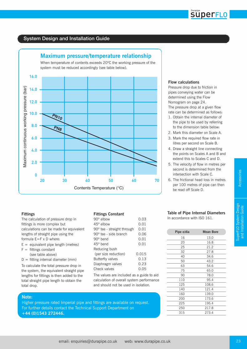
Maximum pressure/temperature relationshipWhen temperature of contents exceeds 20ºC the working pressure of thesystem must be reduced accordingly (see table below).
Table of Pipe Internal DiametersIn accordance with ISO 161.
Pipe o/dia Mean Bore
16 13.0 20 16.8 25 21.2 32 27.8 40 34.6 50 43.2 63 54.6 75 65.0 90 78.0 110 95.4 125 108.6 140 121.4 160 139.0 200 173.6 225 195.4 250 217.8 315 273.4
Fittings The calculation of pressure drop infittings is more complex butcalculations can be made for equivalentlengths of straight pipe using theformula E=F x D where:E = equivalent pipe length (metres)F = fittings constant
(see table above)D = fitting internal diameter (mm)
To calculate the total pressure drop inthe system, the equivalent straight pipelengths for fittings is then added to thetotal straight pipe length to obtain thetotal drop.
Note:Higher pressure rated Imperial pipe and fittings are available on request.For further details contact the Technical Support Department on +44 (0)1543 272446.
Fittings Constant90º elbow 0.0345º elbow 0.0190º tee - straight through 0.0190º tee - side branch 0.0690º bend 0.0145º bend 0.01Reducing bush (per size reduction) 0.015Butterfly valves 0.13Diaphragm valves 0.23Check valves 0.05
The values are included as a guide to aidcalculation of overall system performanceand should not be used in isolation.
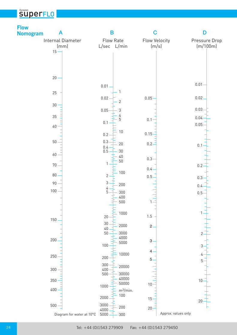
Flow calculationsPressure drop due to friction inpipes conveying water can bedetermined using the FlowNomogram on page 24.The pressure drop at a given flowrate can be determined as follows:1. Obtain the internal diameter of
the pipe to be used by referringto the dimension table below:
2. Mark this diameter on Scale A.3. Mark the required flow rate in
litres per second on Scale B.4. Draw a straight line connecting
the points on Scales A and B andextend this to Scales C and D.
5. The velocity of flow in metres persecond is determined from theintersection with Scale C.
6. The frictional head loss in metresper 100 metres of pipe can thenbe read off Scale D.
SuperFLO System Design
and Installation Guide
Tel: +44 (0)1543 279909 Fax: +44 (0)1543 27945024
0.01
0.02
0.05
0.1
0.2
0.30.40.5
1
2
345
20
304050
100
200
300400500
1000
2000
300040005000 300
200
100
500004000030000
20000
10000
500040003000
2000
1000
500400300
200
100
504030
20
10
543
2
1
m3/min.
0.05
0.1
0.15
0.2
0.3
0.4
0.5
1
1.5
2
3
4
5
10
15
20Approx. values only
0.01
0.02
0.03
0.04
0.05
0.1
0.2
0.3
0.4
0.5
1
2
3
4
5
10
20
Pressure Drop(m/100m)
Flow Velocity(m/s)
Flow RateL/sec L/min
Internal Diameter(mm)
Diagram for water at 10°C
15
20
30
40
50
60
70
80
90
100
150
200
250
300
350
400
500
25
35
A B C DFlowNomogram
email: [email protected] web: www.durapipe.co.uk 25
SuperFLO System Design
and Installation Guide
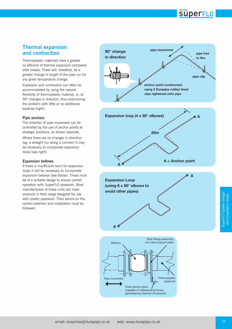
Thermal expansionand contractionThermoplastic materials have a greater co-efficient of thermal expansion comparedwith metals. There will, therefore, be agreater change in length of the pipe run forany given temperature change.
Expansion and contraction can often beaccommodated by using the naturalflexibility of thermoplastic material, ie. at90° changes in direction, thus overcomingthe problem with little or no additionalexpense (right).
Pipe anchorsThe direction of pipe movement can becontrolled by the use of anchor points atstrategic positions, as shown opposite.
Where there are no changes in direction(eg. a straight run along a corridor) it maybe necessary to incorporate expansionloops (see right).
Expansion bellowsIf there is insufficient room for expansionloops it will be necessary to incorporateexpansion bellows (see below). These mustbe of a suitable design to ensure correctoperation with SuperFLO pipework. Mostmanufacturers of these units will haveproducts in their range designed for usewith plastic pipework. Their advice on thecorrect selection and installation must befollowed.
BellowsStub flange assembly
c/w valve support plate
Pipe movement
Fixed anchor point(capable of withstanding forcesgenerated by thermal movement)
Thermoplasticpipework
pipe movementpipe free
to flex
pipe clip
anchor point constructed
using 3 Durapipe rubber lined
clips tightened onto pipe
90° change
in direction
Expansion loop (4 x 90° elbows)
Expansion Loop
(using 6 x 90° elbows to
avoid other pipes)
A
A
A
A
A = Anchor point
20m
Tel: +44 (0)1543 279909 Fax: +44 (0)1543 27945026
500
400
300
200
1009080706050
40
30
20
Example
15.15
1098765
4
3
2
0.1 0.2 0.3 0.4 0.5 0.6 0.8 1.0 1.51.2 2.0 2.5 3.0
H (m)
L (m
m)
2
16mm
20mm
25mm
40mm
50mm
75mm63mm
90mm
110mm
140mm
160mm
225mm
250mm
315mm
32mm
H⁄2
L2
H
H⁄2 max
L2
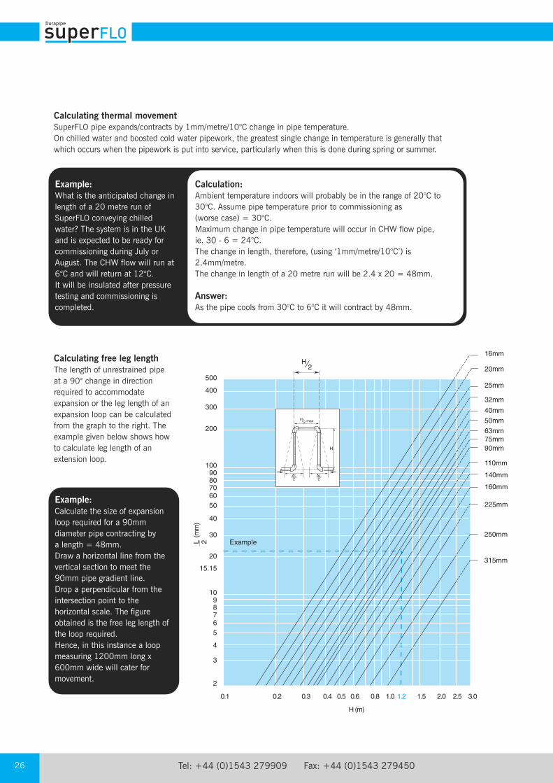
Example:Calculate the size of expansionloop required for a 90mmdiameter pipe contracting by a length = 48mm.Draw a horizontal line from thevertical section to meet the90mm pipe gradient line. Drop a perpendicular from theintersection point to thehorizontal scale. The figureobtained is the free leg length ofthe loop required.Hence, in this instance a loopmeasuring 1200mm long x600mm wide will cater formovement.
Calculating free leg lengthThe length of unrestrained pipeat a 90° change in directionrequired to accommodateexpansion or the leg length of anexpansion loop can be calculatedfrom the graph to the right. Theexample given below shows howto calculate leg length of anextension loop.
Calculating thermal movementSuperFLO pipe expands/contracts by 1mm/metre/10°C change in pipe temperature.On chilled water and boosted cold water pipework, the greatest single change in temperature is generally thatwhich occurs when the pipework is put into service, particularly when this is done during spring or summer.
Example:What is the anticipated change inlength of a 20 metre run ofSuperFLO conveying chilledwater? The system is in the UKand is expected to be ready forcommissioning during July orAugust. The CHW flow will run at6°C and will return at 12°C. It will be insulated after pressuretesting and commissioning iscompleted.
Calculation:Ambient temperature indoors will probably be in the range of 20°C to30°C. Assume pipe temperature prior to commissioning as(worse case) = 30°C.Maximum change in pipe temperature will occur in CHW flow pipe,ie. 30 - 6 = 24°C.The change in length, therefore, (using ‘1mm/metre/10°C’) is2.4mm/metre.The change in length of a 20 metre run will be 2.4 x 20 = 48mm.
Answer:As the pipe cools from 30°C to 6°C it will contract by 48mm.

email: [email protected] web: www.durapipe.co.uk 27
SuperFLO System Design
and Installation Guide
Jointing guideDurapipe SuperFLO pipes and fittings aredesigned for an interference fit. AlthoughDurapipe SuperFLO solvent cement hasgood gap filling properties no attemptshould be made to increase the clearancebetween the pipes and fittings.
Solvent cement welding offers a simple andquick means of constructing high integrity,leak-free joints.
The solvent cement operates by chemicallysoftening the joint surfaces. Joint integritywill be greatly reduced if these surfaces arenot clean and properly prepared.
Durapipe SuperFLO solvent cement must be used.
The jointing procedure detailed here mustbe followed.
This relates to the new ‘one-step’ solventcement. With this cement it is notnecessary to abrade pipe or fitting.
An indication of the number of joints to bemade per litre of cement is as follows:
Stage 1The pipe must be cut clean andsquare. A suitable wheel cutter willeliminate swarf.
Stage 2Chamfer the end of the pipe using acoarse file or suitable chamferingtool. The chamfer should beapproximately 45° by 3mm to 5mmdepending on the pipe size.
Stage 3Mark the pipe a known distancefrom the end and clear of the area tobe cleaned. This mark should beused to confirm full insertion of pipeinto socket of fitting.
Stage 4Clean surfaces thoroughly withDurapipe Eco cleaner using lintfree cloth/paper towel.
Drying timesThe drying times will vary with fit, amount of solvent cement applied, ambienttemperature and working pressure. It is recommended that, wherever possible,joints of sizes up to 225mm are allowed to dry for at least 24 hours. Sizes 250 mm and 315mm require a minimum of 48 hours. These guidelinesare based on an ambient temperature of between 10°C to 40°C. Longer dryingtimes will be required at lower and higher ambient temperatures.
It is recognised that there will be occasions when the system will need to be putinto service within a few hours of being made. A rough but safe working guidewhere the ambient temperature is between 10°C to 40°C and the contentstemperature does not exceed 20°C is as follows:
Size Recommended Joints per (mm) container size litre
16 - 32 0.5 litre 400 40 - 63 0.5 litre 200 75 - 110 0.5 litre 70 125 - 140 1 litre 20 160 - 225 1 litre 10 250 - 315 1 litre 5
Size Up to 90mm 140mm 200mm 250mm range 75mm to 125mm & 160mm & 225mm & 315mm
Drying time 0.5 hour/bar 1.0 hour/bar 1.5 hour/bar 2.0 hours/bar 48hrs min

Tel: +44 (0)1543 279909 Fax: +44 (0)1543 27945028
Stage 5Using a clean brush apply cement to the pipe and fitting. The joint surfaces
should be completely covered by cement. For larger pipe sizes, cementshould be applied using an appropriate size brush and tin of cement. It isimportant to apply cement quickly to enable assembly without excessive
force being required.
Stage 7Wipe off excess cement. Bead can be left unwiped for neatness.
Check for and remove any runs of cement on face of flanges/unions or inside fittings. Using the mark previously made, check that the
pipe has been fully inserted.Do not disturb a joint for least 10 minutes. On larger sizes do not subject
the joint to bending or twisting forces for at least 4 hours (see below).When making subsequent joints, which can be done without waiting, take
care not to transmit forces to freshly made joints in the system.
Stage 6Immediately after applications of cement, push pipe fully home into the
fitting. Do not twist. Hold the pipe and the fitting for times varying from afew seconds on size 16mm up to 1 minute on size 315mm. Application ofthe correct amount of cement will result in a neat bead of cement at the
edge of the fitting and at the edge of the pipe.
Jointing precautionsDurapipe SuperFLO solvents cement and Eco cleaner are hazardous, flammable, substances. Read instructions onlabels, follow instructions, and take appropriate measures toreduce hazards. Always wear appropriate personal protectiveequipment.
DO NOT use near naked flames
DO NOT smoke in the working area
DO NOT use in confined spaces
DO NOT joint in the rain or wet conditions
DO NOT use dirty brushes
DO NOT use dirty or oily cleaning cloths
DO NOT use the same brush for different cements
DO NOT dilute or decant Durapipe SuperFLO solvent cement
Important information1. The integrity of Durapipe SuperFLO
systems may be affected if SuperFLOone-step Thixotropic Solvent cement andDurapipe Eco cleaner is not used.Durapipe UK disclaims responsibility forany Durapipe SuperFLO systemconstructed with any other cement or notfabricated in accordance with theinstructions herein.
2. Use the appropriate size of solventcement tin/container and method ofapplication for the size of pipe and fittingto be assembled.
3. To achieve the correct speed ofapplication on sizes 140mm and above,cement should be applied simultaneouslyto pipe and fitting, by two people.
email: [email protected] web: www.durapipe.co.uk 29
SuperFLO System Design
and Installation Guide
Design of pipe supports and clipsPipe supports (eg. drop rods) should besufficiently rigid to provide lateral restraint to thepipework, otherwise the pipes may ‘snake’. This will prevent the expansion loop from workingcorrectly, and may even reduce the service life of the pipework.
Pipe clips must allow free, unrestricted, axialmovement. The pipe clips shown on pages 21and 22 meet these requirements.
Pipe clipsSome rubber lined clips contain harmfulsubstances which can reduce the service life ofthe pipework. We recommend the use of pipeclips as shown on pages 21 and 22.
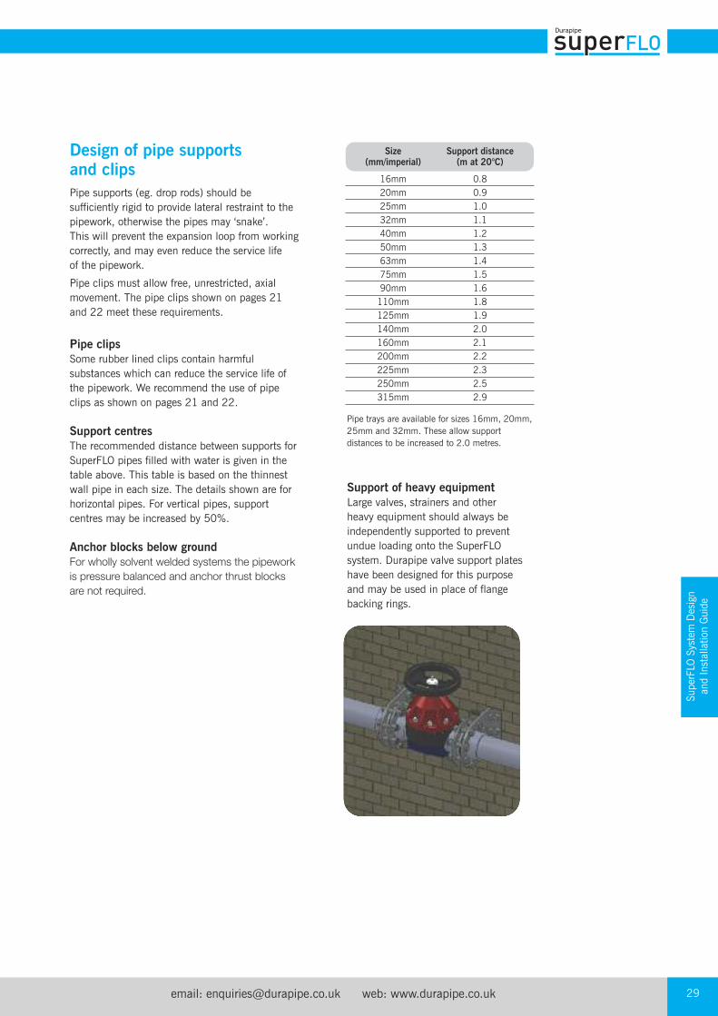
Support centresThe recommended distance between supports forSuperFLO pipes filled with water is given in thetable above. This table is based on the thinnestwall pipe in each size. The details shown are forhorizontal pipes. For vertical pipes, supportcentres may be increased by 50%.
Anchor blocks below groundFor wholly solvent welded systems the pipework
is pressure balanced and anchor thrust blocks
are not required.
Pipe trays are available for sizes 16mm, 20mm,25mm and 32mm. These allow supportdistances to be increased to 2.0 metres.
Size Support distance (mm/imperial) (m at 20°C)
16mm 0.8 20mm 0.9 25mm 1.0 32mm 1.1 40mm 1.2 50mm 1.3 63mm 1.4 75mm 1.5 90mm 1.6 110mm 1.8 125mm 1.9 140mm 2.0 160mm 2.1 200mm 2.2 225mm 2.3 250mm 2.5 315mm 2.9
Support of heavy equipmentLarge valves, strainers and otherheavy equipment should always beindependently supported to preventundue loading onto the SuperFLOsystem. Durapipe valve support plateshave been designed for this purposeand may be used in place of flangebacking rings.
Tel: +44 (0)1543 279909 Fax: +44 (0)1543 27945030
Flexible hoses and metal threaded fittings
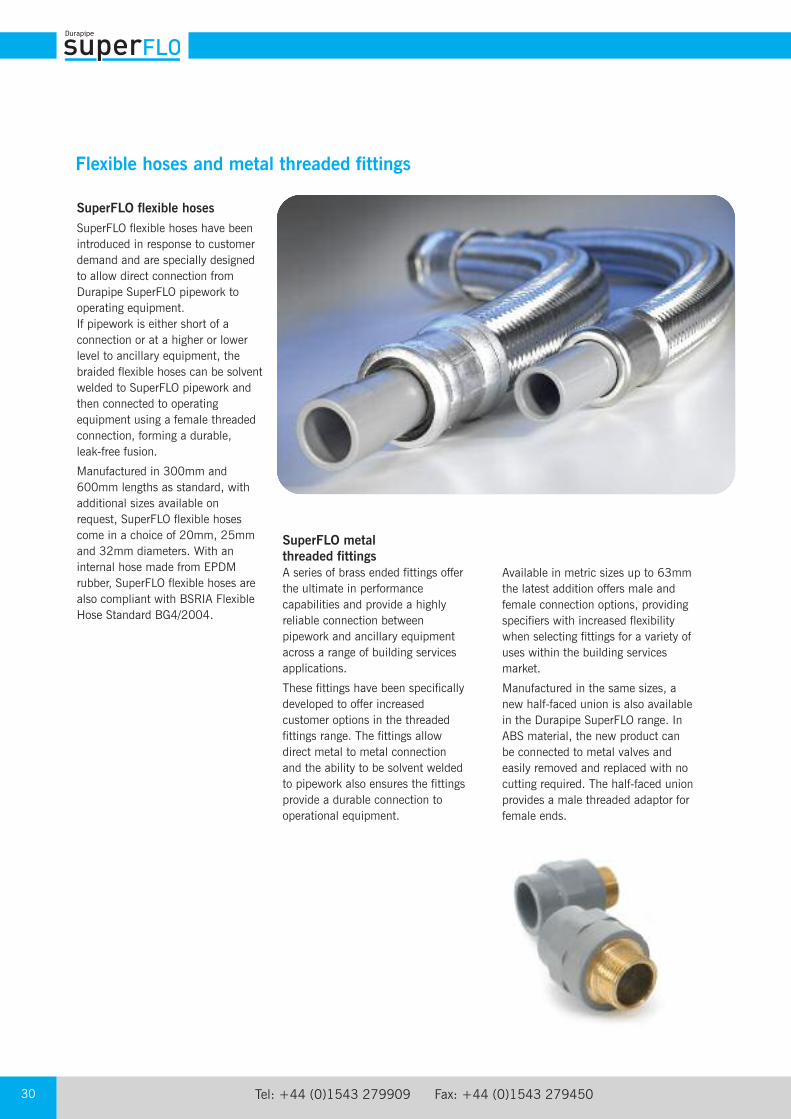
SuperFLO flexible hosesSuperFLO flexible hoses have beenintroduced in response to customerdemand and are specially designedto allow direct connection fromDurapipe SuperFLO pipework tooperating equipment.If pipework is either short of aconnection or at a higher or lowerlevel to ancillary equipment, thebraided flexible hoses can be solventwelded to SuperFLO pipework andthen connected to operatingequipment using a female threadedconnection, forming a durable, leak-free fusion.
Manufactured in 300mm and600mm lengths as standard, withadditional sizes available onrequest, SuperFLO flexible hosescome in a choice of 20mm, 25mmand 32mm diameters. With aninternal hose made from EPDMrubber, SuperFLO flexible hoses arealso compliant with BSRIA FlexibleHose Standard BG4/2004.
SuperFLO metal threaded fittingsA series of brass ended fittings offerthe ultimate in performancecapabilities and provide a highlyreliable connection betweenpipework and ancillary equipmentacross a range of building servicesapplications.
These fittings have been specificallydeveloped to offer increasedcustomer options in the threadedfittings range. The fittings allowdirect metal to metal connectionand the ability to be solvent weldedto pipework also ensures the fittingsprovide a durable connection tooperational equipment.
Available in metric sizes up to 63mmthe latest addition offers male andfemale connection options, providingspecifiers with increased flexibilitywhen selecting fittings for a variety ofuses within the building servicesmarket.
Manufactured in the same sizes, anew half-faced union is also availablein the Durapipe SuperFLO range. InABS material, the new product canbe connected to metal valves andeasily removed and replaced with nocutting required. The half-faced unionprovides a male threaded adaptor forfemale ends.
email: [email protected] web: www.durapipe.co.uk 31
SuperFLO System Design
and Installation Guide
Using bushes, reducers, threaded adaptors and flanges
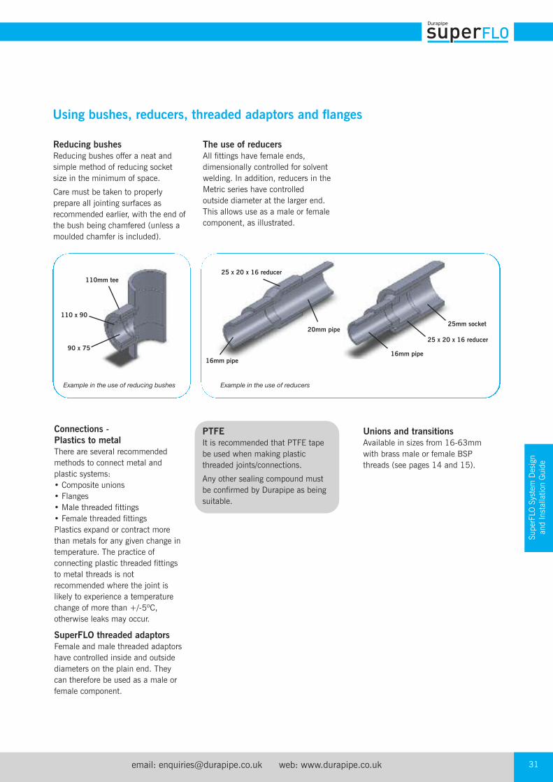
Reducing bushes Reducing bushes offer a neat andsimple method of reducing socketsize in the minimum of space.
Care must be taken to properlyprepare all jointing surfaces asrecommended earlier, with the end ofthe bush being chamfered (unless amoulded chamfer is included).
Connections -Plastics to metal There are several recommendedmethods to connect metal andplastic systems:• Composite unions• Flanges• Male threaded fittings• Female threaded fittingsPlastics expand or contract morethan metals for any given change intemperature. The practice ofconnecting plastic threaded fittingsto metal threads is notrecommended where the joint islikely to experience a temperaturechange of more than +/-5ºC,otherwise leaks may occur.
SuperFLO threaded adaptorsFemale and male threaded adaptorshave controlled inside and outsidediameters on the plain end. Theycan therefore be used as a male orfemale component.
PTFEIt is recommended that PTFE tapebe used when making plasticthreaded joints/connections.
Any other sealing compound mustbe confirmed by Durapipe as beingsuitable.
Unions and transitionsAvailable in sizes from 16-63mmwith brass male or female BSPthreads (see pages 14 and 15).
The use of reducersAll fittings have female ends,dimensionally controlled for solventwelding. In addition, reducers in theMetric series have controlledoutside diameter at the larger end.This allows use as a male or femalecomponent, as illustrated.
110mm tee
90 x 75
110 x 90
25 x 20 x 16 reducer
16mm pipe
20mm pipe25mm socket
25 x 20 x 16 reducer
16mm pipe
Example in the use of reducing bushes Example in the use of reducers
Tel: +44 (0)1543 279909 Fax: +44 (0)1543 27945032
Stub flanges are available from16mm to 315mm.
The correct galvanised mild steelbacking ring and rubber gasketmust be used with both types.
Flange bolting procedureThe following procedure isrecommended for installingDurapipe SuperFLO flanges:
1. Inspect flange faces and ensure that they are clean and undamaged.
2. Check that the correct backingring and rubber gaskets havebeen supplied. Durapipesupplies a matched system of flanges and backing rings.
3. Loosely assemble flanges.Ensure that flanges and boltholes align and that the flangefaces are parallel. Ensure thatthe gasket is correctly positionedbetween the flanges.
4. Ensure that the appropriate sizedwashers are placed under bothbolt heads and nuts.
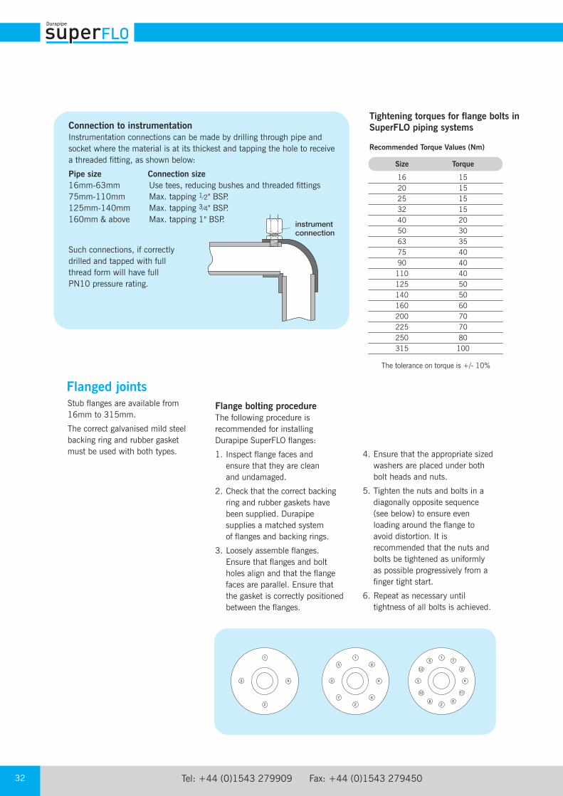
5. Tighten the nuts and bolts in adiagonally opposite sequence(see below) to ensure evenloading around the flange toavoid distortion. It isrecommended that the nuts andbolts be tightened as uniformlyas possible progressively from afinger tight start.
6. Repeat as necessary untiltightness of all bolts is achieved.
Tightening torques for flange bolts inSuperFLO piping systems
Recommended Torque Values (Nm)
1
2
3 4
5
67
8
1
2
3 4
5
6
7
8
11
912
10
1
2
3 4
The tolerance on torque is +/- 10%
Connection to instrumentationInstrumentation connections can be made by drilling through pipe andsocket where the material is at its thickest and tapping the hole to receivea threaded fitting, as shown below:
Pipe size Connection size16mm-63mm Use tees, reducing bushes and threaded fittings75mm-110mm Max. tapping 1⁄2" BSP.125mm-140mm Max. tapping 3⁄4" BSP.160mm & above Max. tapping 1" BSP.
instrumentconnection
Size Torque
16 15 20 15 25 15 32 15 40 20 50 30 63 35 75 40 90 40 110 40 125 50 140 50 160 60 200 70 225 70 250 80 315 100
Such connections, if correctlydrilled and tapped with fullthread form will have fullPN10 pressure rating.
Flanged joints
email: [email protected] web: www.durapipe.co.uk 33
SuperFLO System Design
and Installation Guide
Additional Important Information
• Thermal insulationSome insulation products can contain substances capable of havinga detrimental effect on thermoplastic pipework eg. Certain types offoam rubber insulations can cause pipes to fail where the ABS isconveying liquids at temperatures above 30°C.
Recommended insulation – a list of some of the common types ofinsulation materials known to be suitable with ABS pipework are as follows;Fibre wool, such as ‘Rockwool’Armaflex Class 1 HTKoolphen K Phenolic foamPolystyreneNote: The above list is not exhaustive – please contact our Technical Support Department if further assistance is required.Some adhesives can also be detrimental. Do not bond insulation toABS. (The comment also applies to any tapes, adhesives, or othersubstances used to secure the heating tape to the pipework.)
• Trace heatingThe selection of heating tapes with silicone rubber, woven wire, orwoven polyester outer sheaths will eliminate the risk of plasticizermigration. These tapes are therefore preferred for use onthermoplastic systems.
• Pipe contents identification Do not put self-adhesive labels directly on to pipe surfaces as thismay be detrimental to pipe performance. It is recommended thatsome sort of barrier, such as aluminium foil, is placed between pipeand identification label.
• Intumescent mastic and mastic sealantsCertain mastic sealants are formulated with phthalates. Phthalates
are known to be extremely aggressive toward ABS materials, and
therefore confirmation of the suitability of any mastic sealant
should be determined before being used in conjunction with
ABS pipework.
• Pipe clips It is important that the composition of pipe clips and their linings donot include substances which might have a detrimental effect uponthe ABS pipe. Please check for suitability before use.We strongly recommend the use of Durapipe Cobra clips for pipesizes up to and including 160mm OD / 6”NB, wherevercircumstances allow.
• Contact with synthetic oilsSome synthetic oils are unsuitable for use with thermoplastic pipesystems. The main types of synthetic oils identified as beingincompatible with thermoplastic pipe systems includes Esters,Polyalkylene Glycols, and Organic Phosphates.It should be noted that some metal coil manufacturers use these oilsin their manufacturing process. This is normally drained from thecoil. If it is suspected that residues of oil may remain in the coil itshould be filled with methylated spirits, then thoroughly flushedwith water.
• Freezing conditionsPrecautions should be taken to prevent contents freezing, as this cancause pipework to split.Mono-ethylene glycol can be added to the system to lower thefreezing point.
• Contact with fluxes Some fluxes can be detrimental to ABS. Care should be taken whensoldering copper pipework directly above, or close to, ABS pipework.
• Buried pipesDo not lay ABS in contaminated ground eg. ‘brown-field’ sites.Do not lay ABS in ground where spillages of chemicals may occur.
• Thread sealantsSome thread sealants can damage ABS. PTFE tape should be usedwhen making threaded connections.
• Resistance to U.V. (sunlight)Care should be taken to avoid exposure to U.V. light, eg. sunlight,particularly during storage. Thus will cause discolouration anddeterioration of the ABS material. Whilst this is a surface effect only it is recommended that precautions be taken to prevent thishappening. If stored outdoors pipe should be covered with opaquesheeting. If installed outdoors it can be protected from the effects of U.V. by insulating or painting.
• Pressure surges Durapipe ABS pipework can withstand pressure surges within thelimitations detailed within CP312 part 2:1973 and its amendmentdated 1977.On no account should pressure surges be allowed to exceed themaximum continuous working pressure.
Mechanical, Physical and Electrical Data Test Method Value
Mechanical Tensile strength at yield (23ºC) ASTM D635 45MN/m2
Tensile modulus of elasticity ASTM D635 2200MN/m2
Poisson’s ratio - 0.35Izod impact strength at 23ºC (notched) ASTM D256 (1/8") 35kJ/m2
Charpy impact strength at 23ºC (notched) - 20kJ/m2
Physical Specific gravity ASTM D792 1.04Softening point (BS2782:Part 1 Method120B:1976) ISO R 306 (5kg) (heating rate unknown) 99ºCLinear co-efficient of thermal expansion - 10.1 x 10⁻⁵/ºCISO75 HDT/Ae 1.8Mpa ASTM D648 (unannealed, 1/4", 18.56 kgf/cm2) 78ºCThermal conductivity - 0.157W/mºCSpecific heat - 2.1kJ/kg.KSelf ignition temperature - 540ºC
Electrical Dielectric constant - 2.9 at 103Hz 2.8 at 106HzVolume resistivity IEC 93 - >1.E14ohm m
Additional Important
Information
Tel: +44 (0)1543 279909 Fax: +44 (0)1543 27945034
Handling and storageThe high impact strength of DurapipeSuperFLO systems provides someprotection against damage but careshould be taken at all stages ofhandling, transportation and storage.
Pipe must be transported by asuitable vehicle and properly loadedand unloaded, eg., wherever possiblemoved by hand or mechanical liftingequipment. It must not be draggedacross the ground.
The storage should be flat, level andfree from sharp stones.
LengthsPipe lengths stored individually shouldbe stacked in a pyramid not morethan one metre high, with the bottomlayer fully restrained by wedges.Where possible, the bottom layer ofpipes should be laid on timberbattens at one-metre centres. On site,pipes may be laid out individually instrings. (Where appropriate,protective barriers should be placedwith adequate warning signs andlamps.)
BundlesBundled packs of pipe should bestored on clear, level ground with thebattens supported from the outside bytimbers or concrete blocks. For safety,bundled packs should not be stackedmore than three metres high.
Smaller pipes may be nested insidelarger pipes. Side bracing should beprovided to prevent stack collapse.
Similar precautions should be takenwith fittings and these should be keptin protective wrappings until requiredfor use.
Health and Safety at Work Actand COSHH RegulationsAttention is drawn to therequirements in the UK of this Act and to the 1988 Control ofSubstances Hazardous to Health(COSHH) Regulations. Durapipecannot accept responsibility foraccidents arising from the misuse of its products because of badinstallation or incorrect application.
Material safety dataMaterial Safety Data sheets areavailable on our website.
Handling SuperFLO pipes and fittingsAlways adopt good storage andhandling practice. Advice is availableupon request.
Jointing and installationDurapipe SuperFLO solvent cementmust be used exclusively forfabrication of the SuperFLO system.Performance guarantees are null andvoid if other solvent cements are used.
Storage and installation outdoorsCare should be taken to avoidexposure to sunlight during storage.This may cause discolouration anddeterioration of the SuperFLO material.Whilst this is a surface effect only, it isrecommended that precautions betaken to prevent this happening (othersources of UV light can have a similareffect). If SuperFLO is installed outdoors werecommend that it is protected fromthe effects of sunlight.
Storage of loose pipes
Storage of bundles
email: [email protected] web: www.durapipe.co.uk 35
Additional Important
Information
Filling and flushingWhen purchasing chemicals for eitherflushing or long-term system use,suppliers should be advised that this is forSuperFLO material. Guidance on thesuitability of various system flushing orfilling fluids with SuperFLO can be foundin the Durapipe Chemical Data catalogue.
TestingIt is suggested that the following testprocedure be followed, after joints havebeen allowed to dry for the appropriateminimum time (at least 24 hours up to225mm, sizes 250mm and 315mmrequire a minimum of 48 hours at 20°C).
The system should be dividedconveniently into test sections.
Fill section with cold water making surethat no air pockets remain. Do notpressurise at this stage.
Check system for leaks. If none areapparent, check for and remove anyremaining air. Increase pressure up to 3 bar. Do not pressurise further at thisstage.
Leave section pressurised for 10 minutes.If pressure decays, inspect for leaks andrectify as necessary.
If pressure remains constant, slowlyincrease the hydrostatic pressure to 11/2 times nominal operating pressure.
Leave section pressurised for a period notexceeding 1 hour.
During this time pressure should notchange.
ColourDurapipe SuperFLO products are a mid-greycolour, generally in accordance with BS5252,colour ref. 18 B 21 and RAL 7001.The Durapipe SuperFLO Metric System ismanufactured generally in accordance withthe relevant international standards as shownbelow:ISO 15493KIWA 49 and 549DIN 8062 and 8063
Threaded fittings conform to the requirementsof BS 21/DIN 2999/ISO7. Socket dimensionsof Durapipe fittings for solvent weldingcomply with ISO/DIS 727-1.
MaterialsDurapipe SuperFLO material is UK WaterRegulations Advisory Scheme approved forcold water services and is listed in the Water Fittings and Materials Directory.
Durapipe SuperFLO formulation does notcontain any harmful metallic stabilisers.
Gaskets and sealsGaskets and O-Ring seals are made fromEPDM except where stated otherwise.
Pressure surgesDurapipe SuperFLO pipework can withstandpressure surges within the limitations detailedwithin CP312 Part 2:1973 and itsamendment dated 1977.
On no account should pressure surges beallowed to exceed the maximum continuousworking pressure calculated using the graphon page 23.
CautionPersonnel must stand well clear when pressure testing systems. For information regardingpneumatic testing of SuperFLO pipework, contact the Durapipe technical supportdepartment.
Note: If extended times are required to achieve hydrostatic pressure, either leakage hasoccurred or air remains in the line. Inspect for leakage and if none is apparent, reducepressure and check for trapped air. This must be removed before further pressurisationcommences.
PRE-INSULATED PIPEWORK
Duracool
Duracool is a completely innovative pre-insulated ABS pipework systemthat is specially designed to provide reduced installation costs.
Duracool is a complete system of pre-insulated pipe with unique shells for the fittings,
insulation is protected by an attractive polyethylene outer casing.
Fitting is quick and easy, eliminating the need for hot works or manual lagging
and making installation an easy and convenient process.
Key Product Information
• Size Range: 20mm to 225mm
• Pressure Rating: PN10
• Temperature Rating: -40°C to 70°C
Typical Applications
• Chilled water/air conditioning
• Boosted cold water
• Secondary refrigeration
Key Product Features
• Lightweight
• Easy to install
• Cost-efficient installation
• Wide temperature range
• Tough and durable
Pre-insulated pipework
email: [email protected] web: www.durapipe.co.uk 37
Pre-insulated pipework
Duracool
Duracool system overview
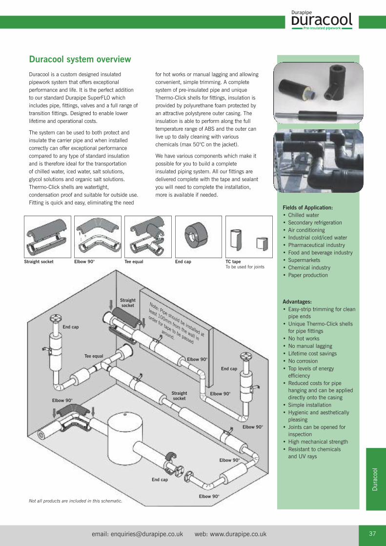
Straight socket Elbow 90° Tee equal End cap
End cap
End cap
Elbow 90°
Elbow 90°
Elbow 90°
Elbow 90°
Elbow 90°
End cap
Elbow 90°
Straightsocket
Straightsocket
Tee equal
TC tapeTo be used for joints
Not all products are included in this schematic.
Note: Pipe should be installed at
least 100mm from the wall in
order for tape to be passed
around.
Fields of Application:• Chilled water• Secondary refrigeration• Air conditioning• Industrial cold/iced water• Pharmaceutical industry• Food and beverage industry• Supermarkets• Chemical industry• Paper production
Advantages:• Easy-strip trimming for cleanpipe ends
• Unique Thermo-Click shellsfor pipe fittings
• No hot works• No manual lagging• Lifetime cost savings• No corrosion• Top levels of energyefficiency
• Reduced costs for pipehanging and can be applieddirectly onto the casing
• Simple installation• Hygienic and aestheticallypleasing
• Joints can be opened forinspection
• High mechanical strength• Resistant to chemicals and UV rays
for hot works or manual lagging and allowingconvenient, simple trimming. A completesystem of pre-insulated pipe and uniqueThermo-Click shells for fittings, insulation isprovided by polyurethane foam protected byan attractive polystyrene outer casing. Theinsulation is able to perform along the fulltemperature range of ABS and the outer canlive up to daily cleaning with variouschemicals (max 50°C on the jacket).
We have various components which make itpossible for you to build a completeinsulated piping system. All our fittings aredelivered complete with the tape and sealantyou will need to complete the installation,more is available if needed.
Duracool is a custom designed insulatedpipework system that offers exceptionalperformance and life. It is the perfect additionto our standard Durapipe SuperFLO whichincludes pipe, fittings, valves and a full range oftransition fittings. Designed to enable lowerlifetime and operational costs.
The system can be used to both protect andinsulate the carrier pipe and when installedcorrectly can offer exceptional performancecompared to any type of standard insulation and is therefore ideal for the transportation of chilled water, iced water, salt solutions, glycol solutions and organic salt solutions. Thermo-Click shells are watertight,condensation proof and suitable for outside use.Fitting is quick and easy, eliminating the need
Pre-insulated pipework
Tel: +44 (0)1543 279909 Fax: +44 (0)1543 27945038
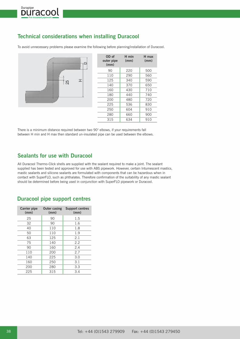
To avoid unnecessary problems please examine the following before planning/installation of Duracool.
Technical considerations when installing Duracool
There is a minimum distance required between two 90° elbows, if your requirements fallbetween H min and H max then standard un-insulated pipe can be used between the elbows.
Sealants for use with DuracoolAll Duracool Thermo-Click shells are supplied with the sealant required to make a joint. The sealantsupplied has been tested and approved for use with ABS pipework. However, certain Intumescent mastics,mastic sealants and silicone sealants are formulated with components that can be hazardous when incontact with SuperFLO, such as phthalates. Therefore confirmation of the suitability of any mastic sealantshould be determined before being used in conjunction with SuperFLO pipework or Duracool.
OD of H min H max outer pipe (mm) (mm) (mm)
90 220 500 110 290 560 125 340 590 140 370 650 160 430 710 180 440 740 200 480 720 225 536 830 250 604 910 280 660 900 315 634 910
Carrier pipe Outer casing Support centres (mm) (mm) (mm)
25 90 1.5 32 90 1.6 40 110 1.8 50 110 1.9 63 125 2.1 75 140 2.2 90 160 2.4 110 200 2.7 140 225 3.0 160 250 3.1 200 280 3.3 225 315 3.4
Duracool pipe support centres
email: [email protected] web: www.durapipe.co.uk 39
Pre-insulated pipework
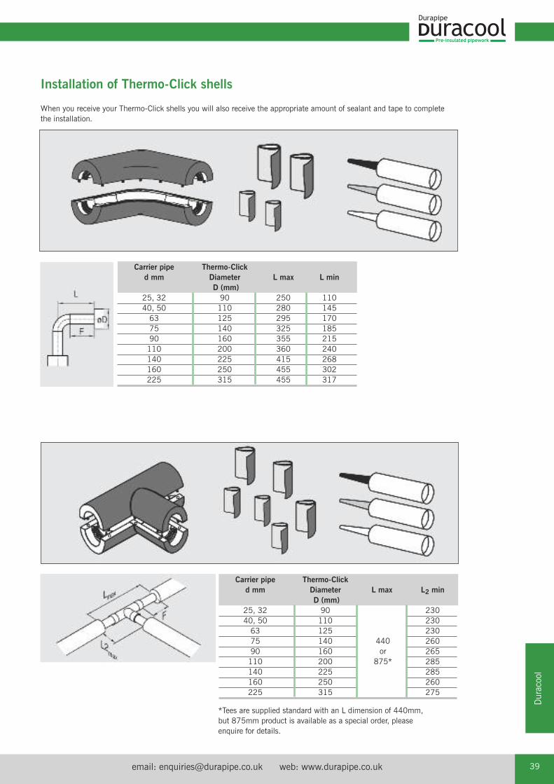
Duracool
When you receive your Thermo-Click shells you will also receive the appropriate amount of sealant and tape to completethe installation.
*Tees are supplied standard with an L dimension of 440mm,but 875mm product is available as a special order, pleaseenquire for details.
Installation of Thermo-Click shells
Carrier pipe Thermo-Click d mm Diameter L max L min D (mm) 25, 32 90 250 110 40, 50 110 280 145 63 125 295 170 75 140 325 185 90 160 355 215 110 200 360 240 140 225 415 268 160 250 455 302 225 315 455 317
Carrier pipe Thermo-Click d mm Diameter L max L2 min D (mm) 25, 32 90 230 40, 50 110 230 63 125 230 75 140 260 90 160 265 110 200 285 140 225 285 160 250 260 225 315 275
440or
875*
Pre-insulated pipework
Tel: +44 (0)1543 279909 Fax: +44 (0)1543 27945040
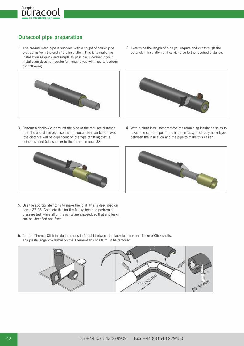
1. The pre-insulated pipe is supplied with a spigot of carrier pipeprotruding from the end of the insulation. This is to make theinstallation as quick and simple as possible. However, if yourinstallation does not require full lengths you will need to performthe following.
2. Determine the length of pipe you require and cut through theouter skin, insulation and carrier pipe to the required distance.
Duracool pipe preparation
3. Perform a shallow cut around the pipe at the required distancefrom the end of the pipe, so that the outer skin can be removed(the distance will be dependent on the type of fitting that isbeing installed (please refer to the tables on page 38).
4. With a blunt instrument remove the remaining insulation so as toreveal the carrier pipe. There is a thin ‘easy-peel’ polythene layerbetween the insulation and the pipe to make this easier.
5. Use the appropriate fitting to make the joint, this is described onpages 27-28. Compete this for the full system and perform apressure test while all of the joints are exposed, so that any leakscan be identified and fixed.
6. Cut the Thermo-Click insulation shells to fit tight between the jacketed pipe and Thermo-Click shells. The plastic edge 25-30mm on the Thermo-Click shells must be removed.
email: [email protected] web: www.durapipe.co.uk 41
Pre-insulated pipework
Duracool
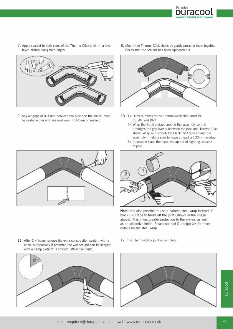
9. Any air-gaps of 0-3 mm between the pipe and the shells, mustbe sealed either with mineral wool, PU-foam or sealant.
10. 1) Outer surfaces of the Thermo-Click shell must be CLEAN and DRY.
2) Wrap the Butyl-alutape around the assembly so that it bridges the gap evenly between the pipe and Thermo-Click shells. Wrap and stretch the black PVC tape around the assembly - making sure to leave at least a 100mm overlap.
3) If possible leave the tape overlap out of sight eg. topside of pipe.
7. Apply sealant to both sides of the Thermo-Click shell, in a levellayer, ø8mm along both edges.
11. After 2-4 hours remove the extra construction sealant with aknife. Alternatively if preferred the wet sealant can be shapedwith a damp cloth for a smooth, attractive finish.
12. The Thermo-Click joint is complete.
Note: It is also possible to use a painted steel wrap instead ofblack PVC tape to finish off the joint (shown in the imageabove). This offers greater protection to the system as well as an attractive finish. Please contact Durapipe UK for moredetails on the steel wrap.
8. Mount the Thermo-Click shells by gently pressing them together.Check that the sealant has been squeezed out.
Pre-insulated pipework
Tel: +44 (0)1543 279909 Fax: +44 (0)1543 27945042
This polyurethane system has been specially formulated for production of half shells. The waterbased foam has a fine cell structure,which results in a high strength. The system does not contain any HCFC – it is blown with CO2 – and therefore has zero Ozonedepletion potential (ODP).
Foam Characteristics at 20°C (hand mixed)
Properties Value Test Method
Density, free rise: 43kg/m³ BS 4370 part 1 meth. 2Density (packed in form) 88kg/m³ BS 4370 part 1 meth. 2
Closed cells 96% ISO 4590
Cell size < 0.2mm EN253Water absorption 2.2 % EN253
Parallel to rise 0.31MPa ISO 844Perpendicular to rise 0.16MPa ISO 844
E-modulus:Parallel to rise 11.7MPa ISO 844Perpendicular to rise 3.9MPa ISO 844
Dimensional stability:(+140ºC/0.02 MPa/48h) < - 5 % DIN 18159-1
Thermal conductivity coefficient:λ10 0,026 W/m°K ISO 8301λ24 0,027 W/m°K ISO 8301λ50 0,030 W/m°K ISO 8301
In Heat Transfer λ is used to denote the heat of vaporisation per mole or latent heat. Burning characteristics: B2 DIN 4102.
Thermo-Click shell outer‘Athpol’ P90UV - extruded UV stabilised high-impact polystyrene (HIPS) sheet.
The following information represents typical property values that are based on information given by polymer raw material suppliers.
Properties Value Test Method
MechanicalTensile Stress at Yield 23MPa ISO 527Flexural Strength 32MPa ISO 178Izod Impact Strength (notched) 23°C 12KJ/M2 ISO 180A
ThermalHeat Deflection Temperature (1.8MPa) 75°C ISO 75Vicat Softening Temperature (5kg - 50c/H) 84°C ISO 306
Density 1.02 ISO 1183Flammability at 1.6mm thickness HB UL94
Chemical Resistance ChartAcids, Inorganic Alcohols E- Weak E Aliphatic Amines E- Strong E Bases E- Strong oxidising F Polyglycols E
Acids, Organic Vegetable oils G- Weak E Pharmaceuticals E- Strong G Salts E
E = Excellent resistant - no attack.G = Good resistant - minor attack.F = Fair - limited resistance. Suitable for short term use only.
Data sheet Thermo-Click insulation shells
For chemical suitability of SuperFLO pressure pipe refer to the Durapipe UK website www.durapipe.co.uk
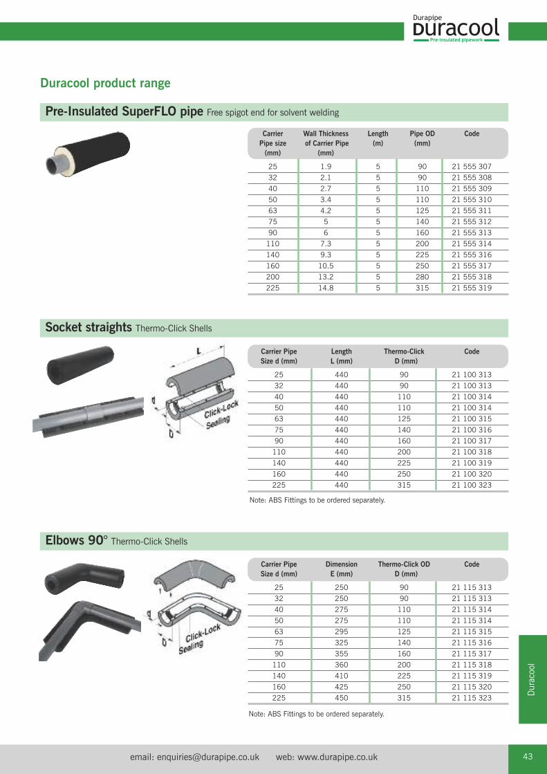
email: [email protected] web: www.durapipe.co.uk 43
Pre-insulated pipework
Duracool
Duracool product range
Pre-Insulated SuperFLO pipe Free spigot end for solvent welding
Carrier Wall Thickness Length Pipe OD CodePipe size of Carrier Pipe (m) (mm)(mm) (mm)
25 1.9 5 90 21 555 307
32 2.1 5 90 21 555 308
40 2.7 5 110 21 555 309
50 3.4 5 110 21 555 310
63 4.2 5 125 21 555 311
75 5 5 140 21 555 312
90 6 5 160 21 555 313
110 7.3 5 200 21 555 314
140 9.3 5 225 21 555 316
160 10.5 5 250 21 555 317
200 13.2 5 280 21 555 318
225 14.8 5 315 21 555 319
Socket straights Thermo-Click Shells
Carrier Pipe Length Thermo-Click CodeSize d (mm) L (mm) D (mm)
25 440 90 21 100 313
32 440 90 21 100 313
40 440 110 21 100 314
50 440 110 21 100 314
63 440 125 21 100 315
75 440 140 21 100 316
90 440 160 21 100 317
110 440 200 21 100 318
140 440 225 21 100 319
160 440 250 21 100 320
225 440 315 21 100 323
Elbows 90° Thermo-Click Shells
Carrier Pipe Dimension Thermo-Click OD CodeSize d (mm) E (mm) D (mm)
25 250 90 21 115 313
32 250 90 21 115 313
40 275 110 21 115 314
50 275 110 21 115 314
63 295 125 21 115 315
75 325 140 21 115 316
90 355 160 21 115 317
110 360 200 21 115 318
140 410 225 21 115 319
160 425 250 21 115 320
225 450 315 21 115 323
Note: ABS Fittings to be ordered separately.
Note: ABS Fittings to be ordered separately.
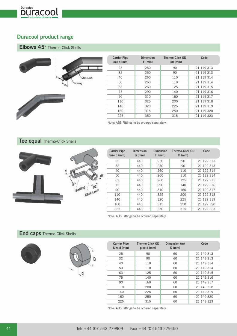
Pre-insulated pipework
Tel: +44 (0)1543 279909 Fax: +44 (0)1543 27945044
Note: ABS Fittings to be ordered separately.
Duracool product range
Elbows 45° Thermo-Click Shells
Tee equal Thermo-Click Shells
Carrier Pipe Dimension Dimension Thermo-Click OD CodeSize d (mm) G (mm) H (mm) D (mm)
25 440 250 90 21 122 313
32 440 250 90 21 122 313
40 440 260 110 21 122 314
50 440 260 110 21 122 314
63 440 260 125 21 122 315
75 440 290 140 21 122 316
90 440 310 160 21 122 317
110 440 325 200 21 122 318
140 440 320 225 21 122 319
160 440 315 250 21 122 320
225 440 350 315 21 122 323
End caps Thermo-Click Shells
Carrier Pipe Thermo-Click OD Dimension (m) CodeSize d (mm) pipe d (mm) D (mm)
25 90 60 21 149 313
32 90 60 21 149 313
40 110 60 21 149 314
50 110 60 21 149 314
63 125 60 21 149 315
75 140 60 21 149 316
90 160 60 21 149 317
110 200 60 21 149 318
140 225 60 21 149 319
160 250 60 21 149 320
225 315 60 21 149 323
Note: ABS Fittings to be ordered separately.
Carrier Pipe Dimension Thermo-Click OD CodeSize d (mm) F (mm) (D) (mm)
25 250 90 21 119 313
32 250 90 21 119 313
40 260 110 21 119 314
50 260 110 21 119 314
63 260 125 21 119 315
75 290 140 21 119 316
90 310 160 21 119 317
110 325 200 21 119 318
140 320 225 21 119 319
160 315 250 21 119 320
225 350 315 21 119 323
Note: ABS Fittings to be ordered separately.
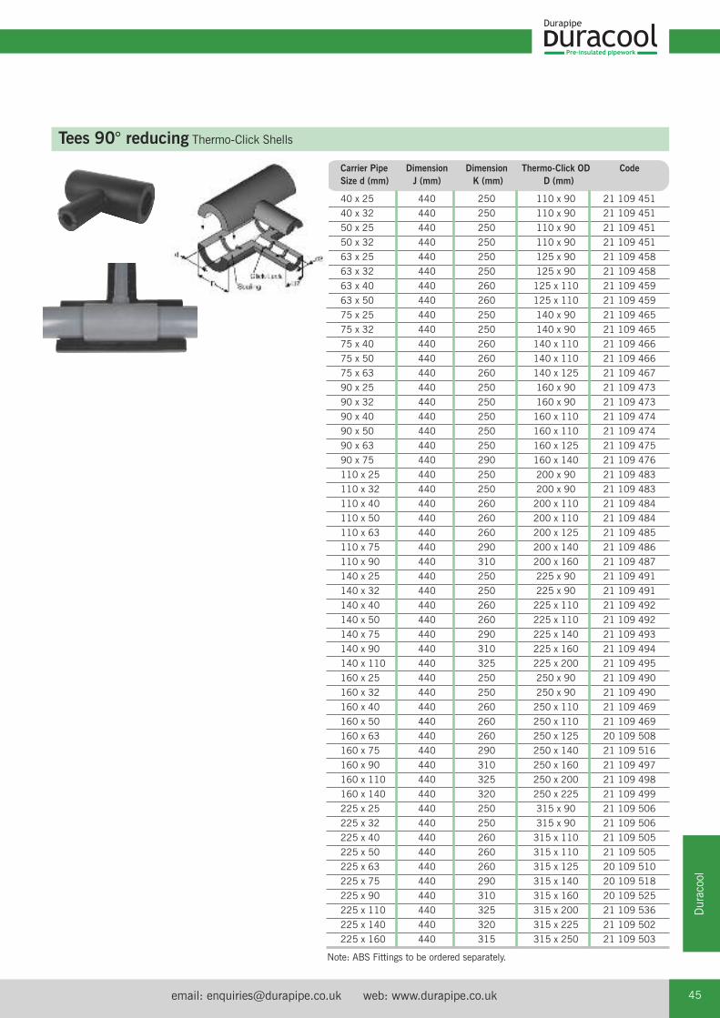
email: [email protected] web: www.durapipe.co.uk 45
Pre-insulated pipework
Duracool
Tees 90° reducing Thermo-Click Shells
Carrier Pipe Dimension Dimension Thermo-Click OD Code Size d (mm) J (mm) K (mm) D (mm)
40 x 25 440 250 110 x 90 21 109 451
40 x 32 440 250 110 x 90 21 109 451
50 x 25 440 250 110 x 90 21 109 451
50 x 32 440 250 110 x 90 21 109 451
63 x 25 440 250 125 x 90 21 109 458
63 x 32 440 250 125 x 90 21 109 458
63 x 40 440 260 125 x 110 21 109 459
63 x 50 440 260 125 x 110 21 109 459
75 x 25 440 250 140 x 90 21 109 465
75 x 32 440 250 140 x 90 21 109 465
75 x 40 440 260 140 x 110 21 109 466
75 x 50 440 260 140 x 110 21 109 466
75 x 63 440 260 140 x 125 21 109 467
90 x 25 440 250 160 x 90 21 109 473
90 x 32 440 250 160 x 90 21 109 473
90 x 40 440 250 160 x 110 21 109 474
90 x 50 440 250 160 x 110 21 109 474
90 x 63 440 250 160 x 125 21 109 475
90 x 75 440 290 160 x 140 21 109 476
110 x 25 440 250 200 x 90 21 109 483
110 x 32 440 250 200 x 90 21 109 483
110 x 40 440 260 200 x 110 21 109 484
110 x 50 440 260 200 x 110 21 109 484
110 x 63 440 260 200 x 125 21 109 485
110 x 75 440 290 200 x 140 21 109 486
110 x 90 440 310 200 x 160 21 109 487
140 x 25 440 250 225 x 90 21 109 491
140 x 32 440 250 225 x 90 21 109 491
140 x 40 440 260 225 x 110 21 109 492
140 x 50 440 260 225 x 110 21 109 492
140 x 75 440 290 225 x 140 21 109 493
140 x 90 440 310 225 x 160 21 109 494
140 x 110 440 325 225 x 200 21 109 495
160 x 25 440 250 250 x 90 21 109 490
160 x 32 440 250 250 x 90 21 109 490
160 x 40 440 260 250 x 110 21 109 469
160 x 50 440 260 250 x 110 21 109 469
160 x 63 440 260 250 x 125 20 109 508
160 x 75 440 290 250 x 140 21 109 516
160 x 90 440 310 250 x 160 21 109 497
160 x 110 440 325 250 x 200 21 109 498
160 x 140 440 320 250 x 225 21 109 499
225 x 25 440 250 315 x 90 21 109 506
225 x 32 440 250 315 x 90 21 109 506
225 x 40 440 260 315 x 110 21 109 505
225 x 50 440 260 315 x 110 21 109 505
225 x 63 440 260 315 x 125 20 109 510
225 x 75 440 290 315 x 140 20 109 518
225 x 90 440 310 315 x 160 20 109 525
225 x 110 440 325 315 x 200 21 109 536
225 x 140 440 320 315 x 225 21 109 502
225 x 160 440 315 315 x 250 21 109 503
Note: ABS Fittings to be ordered separately.
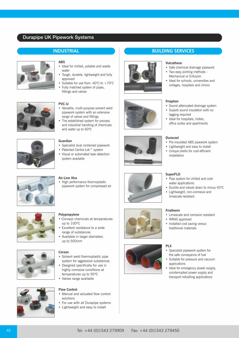
Tel: +44 (0)1543 279909 Fax: +44 (0)1543 27945046
ABS• Ideal for chilled, potable and wastewater
• Tough, durable, lightweight and fullyapproved
• Suitable for use from -40°C to +70°C• Fully matched system of pipes,fittings and valves
PVC-U• Versatile, multi-purpose solvent weldpipework system with an extensiverange of valves and fittings
• The established system for processand industrial handling of chemicalsand water up to 60ºC
Guardian• Specialist dual contained pipework• Patented Centra-Lok™ system• Visual or automated leak detectionsystem available
Flow Control• Manual and actuated flow controlsolutions
• For use with all Durapipe systems• Lightweight and easy to install
Vulcathene• Safe chemical drainage pipework• Two easy jointing methods -Mechanical or Enfusion
• Ideal for schools, universities andcolleges, hospitals and clinics
SuperFLO• Pipe system for chilled and cold water applications
• Ductile and robust down to minus 40ºC• Lightweight, non-corrosive and limescale resistant
Duracool• Pre-insulated ABS pipework system• Lightweight and easy to install• Unique shells for cost-efficientinstallation
Friatherm• Limescale and corrosion resistant• WRAS approved• Installed cost saving versustraditional materials
Friaphon• Sound attenuated drainage system• Superb sound insulation with nolagging required
• Ideal for hospitals, hotels, office suites and apartments
Corzan• Solvent weld thermoplastic pipesystem for aggressive substances
• Designed specifically for use inhighly corrosive conditions attemperatures up to 95ºC
• Valves range available
Polypropylene • Conveys chemicals at temperaturesup to 100ºC
• Excellent resistance to a widerange of substances
• Available in larger diameters up to 500mm
INDUSTRIAL BUILDING SERVICES
Air-Line Xtra • High performance thermoplasticpipework system for compressed air
PLX• Specialist pipework system for the safe conveyance of fuel
• Suitable for pressure and vacuumapplications
• Ideal for emergency power supply,uninterrupted power supply andtransport refuelling applications
Durapipe UK Pipework Systems
email: [email protected] web: www.durapipe.co.uk 47
1. DEFINITIONS:‘Seller’ shall mean Glynwed Pipe Systems Limited, registered in England under number1698059. ‘Buyer’ shall mean any company, organisation or individual to whom a quotationis offered, or whose order is accepted by the Seller.
2. CONDITIONS:All offers, quotations, estimates, acceptances and contracts are subject to these Conditionsof Business and any terms or conditions which any other person shall seek to impose ormake part of any contract shall, so far as is inconsistent with these Conditions of Business,not apply unless expressly agreed by the Seller in writing. The headings in these conditionsare for convenience only and shall not affect their interpretation.
3. QUOTATIONS AND PRICE VARIATION:a) Any quotation given by the Seller is an invitation to the Buyer to make an offer only andno order of the Buyer placed with the Seller in pursuance of a quotation or otherwise shallbe binding on the Seller unless and until it is accepted in writing by the Seller.
b) Unless stated otherwise, all quotations and published price lists are ex works, exclusiveof VAT and shall remain valid for 30 days or such a period as may be quoted butnevertheless the Seller may amend or withdraw any quotation by written or oral notice.Quotations may be varied if the Buyer makes variations in his specifications.
4. STATEMENTS OR REPRESENTATIONS TO THE BUYER:If any statement or representation has been made to the Buyer upon which the Buyer reliesother than in the documents enclosed with the Seller's quotation, the Buyer must set outthat statement or representation in a document to be attached to or endorsed on the orderin which case the Seller may submit a new quotation.
5. DELIVERY - TIME:a) Any period for delivery given at any time and in any manner by the Seller is an estimateonly and is not binding on the Seller. Delivery periods are normally calculated from the laterof:
i) acceptance of order; or
ii) where applicable, the receipt by the Seller of a detailed specification or drawings.
b) Time shall not be deemed to be of the essence of the contract. Failure by the Seller tomeet any quoted delivery period for any part or the whole of the order shall not entitle theBuyer to rescind the contract or to claim damages of any nature.
c) The Seller will endeavour to comply with reasonable requests by the Buyer forpostponement of delivery but shall be under no obligation to do so. Where delivery ispostponed otherwise than due to default by the Seller the Buyer shall pay all costs andexpenses including a reasonable charge for storage and transportation occasioned therebyand an extra charge for split delivery if applicable.
d) The Buyer will receive delivery of any consignment between the hours of 8.00am and4.00pm Monday to Friday inclusive, unless otherwise agreed in writing. Cost incurred bythe Seller arising from the Buyer's refusal to accept consignments within the agreed hoursshall be borne by the Buyer.
6. DELIVERY AND RISK:a) Except where stated to the contrary in the contract, delivery shall be made as follows:
i) where the Buyer provides the transport, delivery shall be made ex the Seller's works;
ii) where the Seller provides the transport, delivery shall be made to the premises of the Buyer, or the premises of the Buyer's customer or works site if the Buyer has requested delivery to be so made but where the Buyer has made such a request the Seller will make a first delivery to the Buyer's customer or works site as so much of the goods as is available for that delivery but subsequent deliveries will be made to the premises of the Buyer.
b) The Seller may at its discretion make partial delivery of orders and invoice the same.
c) Risk in the goods shall pass on delivery.
d) Where goods are sent FOB the Seller's responsibility shall cease when the goods areplaced on board ship or aircraft without the need for the Seller to give notice to the Buyerand the provisions of Section 32(3) of the Sale of Goods Act 1979 shall not apply.
7. OWNERSHIP OF GOODS:a) The goods shall remain the sole and absolute property of the Seller as legal and equitableowner until such time as the Buyer shall have paid to the Seller the contract price togetherwith the full price of any other goods the subject of any contract between the Seller and theBuyer.
b) The Buyer acknowledges that until such time as the property in the goods passes to theBuyer he is in possession of the goods as a bailee and fiduciary agent for the Seller andthe Purchaser shall store the goods in such a manner that they are clearly identifiable asthe property of the Seller.
c) Until payment due under all contracts between the Buyer and the Seller had been madein full, in the event of sale of the goods by the Buyer:
i) the Seller shall be entitled to trace all proceeds of sale received by the Buyer through any bank or other account maintained by the Buyer; and
ii) the Buyer shall if requested by the Seller in writing to so assign its rights to recover the selling price of the goods from the third parties concerned. Such monies to be held separately by the Buyer as agent on behalf of the Seller.
d) The Seller may for the purpose of recovery of its goods enter upon any premises wherethey are stored or where they are reasonably thought to be stored and may repossess thesame.
8. TERMS OF PAYMENT:In the event of default in payment according to the agreed payment terms between theSeller and the Buyer – ie: by the end of the month following the month of despatch of thegoods the Seller shall be entitled without prejudice to any other right or remedy to suspendall further deliveries and to charge interest on any amount outstanding at the rate of 2% permonth until payment in full is made (a part of a month being treated as a full month for thepurpose of calculating interest).
9. SHORTAGES AND DEFECTS APPARENT ON DELIVERY:a) It shall be the responsibility of the Buyer to inspect or arrange for an inspection of thegoods on delivery whether the goods are delivered to the Buyer's premises or to thepremises of the Buyer's customer or to a works site. If no such inspection is made the Buyershall be deemed to have accepted the goods.
b) The Buyer shall have no claim for shortages or defects apparent on inspection unless:
i) a written complaint is made to the Seller within three days of receipt of the goods specifying the shortage or defect; and
ii) the Seller is within seven days of receipt of the complaint given an opportunity to inspect the goods and investigate the complaint before any use is made of the goods.
c) If a complaint is not made to the Seller as herein provided then in respect of suchshortages or defects the goods shall be deemed to be in all respects in accordance withthe contract and the Buyer shall be bound to pay for the same accordingly.
10. CLAIMS FOR DEFECTS NOT APPARENT ON INSPECTION:a) The Buyer shall have no claim for defects not apparent on inspection unless the Selleris notified of defective workmanship or materials within twelve months from delivery of thegoods. Provided that the goods have been installed and applied in accordance with anyrelevant recommendations made by the Seller, the Seller will at its option replace the goodsor refund the net invoiced price in respect of the goods which have been shown to bedefective. If the Seller does so supply substitute goods the Buyer shall be bound to acceptsuch substituted goods in full satisfaction of the obligations of the Seller under the contract.
b) The Buyer shall in any event have no claim or set-off in respect of defects unless a writtencomplaint is sent to the Seller as soon as the defect is noticed and no use is made of thegoods thereafter or alteration made thereto by the Buyer before the Seller is given anopportunity to inspect the goods.
c) The Buyer is responsible for ensuring that the goods are fit for any particular purpose,and no warranty or condition of fitness for any particular purpose is to be implied into thecontract.
11. LIABILITY:Save as stated in Conditions 9 and 10 (and save in respect of death or personal injuryresulting from the negligence of the Seller its servants or agents) the Seller shall not beliable for any claim or claims for direct or indirect consequential or incidental injury loss ordamage made by the Buyer against the Seller whether in contract or in tort (includingnegligence on the part of the Seller its servants or agents) arising out of or in connectionwith any defect in the goods or their fitness or otherwise for any particular purpose or anyact omission neglect or default of the Seller its servants or agents in the performance of thecontract.
12. FORCE MAJEURE:Notwithstanding anything herein contained neither the Buyer nor the Seller is to be heldliable for any delay or failure to carry out the contract due wholly or in part to an act of Godaction by any Government whether British or foreign civil war strikes and/or lockoutswheresoever occurring fire trade disputes floods or unfavourable weather or any materialbecoming unavailable or irreplaceable (whether at all or at commercially acceptable prices)or any other circumstances beyond the control of the Seller.
13. SUB-CONTRACTING:The Seller reserves the right to sub-contract the fulfilment of any order or any part thereof.
14. INSOLVENCY AND BREACH OF CONTRACT:In the event that:
a) the Buyer commits any breach of the contract and fails to remedy such breach (if capable of remedy) within a period of thirty days from receipt of a notice in writing fromthe Seller requesting such remedy; or
b) any distress or execution is levied upon any of the goods or property of the Buyer; or
c) the Buyer offers to make any arrangements with or for the benefit of its creditors or (if an individual) becomes subject to a petition for a bankruptcy order or (being a limitedcompany) has a receiver appointed of the whole or any part of its undertaking property orassets; or
d) an order is made or a resolution is passed or analogous proceedings are taken for thewinding up of the Buyer (save for the purpose of reconstruction or amalgamation withinsolvency and previously approved in writing by the Seller) the Seller shall thereupon beentitled without prejudice to its other rights hereunder forthwith to suspend all furtherdeliveries until the default has been made good or to determine the contract and anyunfulfilled part thereof or at the Seller's option to make partial deliveries. Notwithstandingany such termination the Buyer shall pay to the Seller at the contract rate for all the goodsdelivered up to and including the date of termination.
15. INDUSTRIAL PROPERTY RIGHTS:If goods supplied by the Seller to the Buyer's design or specifications infringe or are allegedto infringe any patent or registered design right or copyright the Buyer will indemnify theSeller against all damages, costs and expenses incurred by the Seller as a result of theinfringement or allegation. The Buyer will give the Seller all possible help in meeting anyinfringement claim brought against the Seller.
16. BUYER'S ERROR IN ORDERING:In the event the Buyer orders incorrectly the Seller will be under no obligation to the Buyerto rectify or assist in rectifying the error.
17. LAW AND JURISDICTION:The contract shall be subject in all respects to English Law and to the jurisdiction of theEnglish Courts.
DURAPIPE UK CONDITIONS OF SALE
Distributor
04900010 October 2011
Registered office:
Durapipe UKWalsall Road Norton CanesCannockStaffordshireWS11 9NSUnited KingdomTel: +44 (0)1543 279909Fax: +44 (0)1543 279450email: [email protected]: www.durapipe.co.uk
Durapipe UK reserves the right to modify the details in this publication as products and specifications are updated and improved.The content of this publication is for general information only and it is the user’s responsibility to determine the suitability of anyproduct for the purpose intended.
For further information on all Durapipe UK products and services contact our Customer Services Department as detailed below.
Customer Services Tel: 01543 273100 Fax: 0800 317875
Durapipe UK is a trade name of Glynwed Pipe Systems Ltd. Company Number 1698059.
chilled and cold water pipework